EP1386480B1 - Procede de capture et d'affichage d'une image panoramique numerique a resolution variable - Google Patents
Procede de capture et d'affichage d'une image panoramique numerique a resolution variable Download PDFInfo
- Publication number
- EP1386480B1 EP1386480B1 EP02738233A EP02738233A EP1386480B1 EP 1386480 B1 EP1386480 B1 EP 1386480B1 EP 02738233 A EP02738233 A EP 02738233A EP 02738233 A EP02738233 A EP 02738233A EP 1386480 B1 EP1386480 B1 EP 1386480B1
- Authority
- EP
- European Patent Office
- Prior art keywords
- image
- panoramic
- point
- objective
- points
- Prior art date
- Legal status (The legal status is an assumption and is not a legal conclusion. Google has not performed a legal analysis and makes no representation as to the accuracy of the status listed.)
- Expired - Lifetime
Links
Images


Classifications
-
- G—PHYSICS
- G02—OPTICS
- G02B—OPTICAL ELEMENTS, SYSTEMS OR APPARATUS
- G02B13/00—Optical objectives specially designed for the purposes specified below
- G02B13/06—Panoramic objectives; So-called "sky lenses" including panoramic objectives having reflecting surfaces
-
- H—ELECTRICITY
- H04—ELECTRIC COMMUNICATION TECHNIQUE
- H04N—PICTORIAL COMMUNICATION, e.g. TELEVISION
- H04N23/00—Cameras or camera modules comprising electronic image sensors; Control thereof
- H04N23/50—Constructional details
- H04N23/55—Optical parts specially adapted for electronic image sensors; Mounting thereof
-
- H—ELECTRICITY
- H04—ELECTRIC COMMUNICATION TECHNIQUE
- H04N—PICTORIAL COMMUNICATION, e.g. TELEVISION
- H04N23/00—Cameras or camera modules comprising electronic image sensors; Control thereof
- H04N23/60—Control of cameras or camera modules
- H04N23/698—Control of cameras or camera modules for achieving an enlarged field of view, e.g. panoramic image capture
-
- G—PHYSICS
- G03—PHOTOGRAPHY; CINEMATOGRAPHY; ANALOGOUS TECHNIQUES USING WAVES OTHER THAN OPTICAL WAVES; ELECTROGRAPHY; HOLOGRAPHY
- G03B—APPARATUS OR ARRANGEMENTS FOR TAKING PHOTOGRAPHS OR FOR PROJECTING OR VIEWING THEM; APPARATUS OR ARRANGEMENTS EMPLOYING ANALOGOUS TECHNIQUES USING WAVES OTHER THAN OPTICAL WAVES; ACCESSORIES THEREFOR
- G03B37/00—Panoramic or wide-screen photography; Photographing extended surfaces, e.g. for surveying; Photographing internal surfaces, e.g. of pipe
- G03B37/06—Panoramic or wide-screen photography; Photographing extended surfaces, e.g. for surveying; Photographing internal surfaces, e.g. of pipe involving anamorphosis
Definitions
- the present invention relates to obtaining digital panoramic images and displaying panoramic images on computer screens.
- the figure 1 is a conventional device for performing a digital panoramic image and presenting it on a computer screen.
- the device comprises a digital camera 1 equipped with a panoramic lens 2 of the "fish-eye" type, having an opening angle of the order of 180 °.
- the apparatus 1 is connected to a computer 5, for example a microcomputer, provided with a screen 6.
- the connection to the microcomputer 5 may be permanent, for example when the apparatus 1 is a digital video camera, or temporary, for example when the camera 1 is a digital camera provided with an image memory, the connection then being made when image files must be transferred to the microcomputer.
- the figure 2 schematically represents the appearance of a panoramic image 3 obtained by means of the panoramic lens 2.
- the round appearance of the image is characteristic of the axial symmetry of the panoramic lenses and the image has dark edges 4 which will be deleted later.
- This digital panoramic image is delivered by the apparatus 1 in the form of a computer file containing coded RGBBA image points arranged in a two-dimensional table, "R” being the red pixel of an image point, "V” the pixel green, "B” the blue pixel, and "A" the Alpha parameter or transparency, the parameters R, V, B, A being generally encoded in 8 bits.
- the image file is transferred to the microcomputer 5 which transforms the initial image into a three-dimensional digital image, then presents the user with a sector of the three-dimensional image in a display window 7 occupying all or part of the screen 6.
- the figure 3 schematically illustrates conventional steps of transforming the two-dimensional panoramic image into a panoramic image providing a realistic perspective effect.
- the microcomputer After removing the black edges of the image, the microcomputer has a set of image points forming an image disc 10 of center O and axes OX and OY.
- the image dots of the image disk are transferred in a three-dimensional space defined by an orthogonal axis reference O'X'Y'Z, the axis O'Z being perpendicular to the plane of the image disk.
- the transfer is provided by a mathematical function implemented by an algorithm executed by the microcomputer, and leads to obtaining a set of image points referenced in the O'X'Y'Z reference.
- image points are for example coded in spherical coordinates RVBA ( ⁇ , ⁇ ), ⁇ being the latitude and ⁇ the longitude of an image point, the angles ⁇ and ⁇ being coded on 4 to 8 bytes (IEEE standard).
- RVBA spherical coordinates
- ⁇ being the latitude and ⁇ the longitude of an image point
- the angles ⁇ and ⁇ being coded on 4 to 8 bytes (IEEE standard).
- These image points form a half-sphere 11 when the panoramic lens used has an opening of 180 °, otherwise a half-sphere portion.
- the microcomputer thus has a virtual image in the form of a half-sphere of which a sector 12, corresponding to the display window 7, is presented on the screen ( Fig. 1 ) considering that the observer is on the central point O 'of the axis system O'X'Y'Z, which defines with the center O "of the image sector 12, a direction O'O" called " position of the gaze ".
- the conventional panoramic lenses In order to prevent the displayed image sector 12 from having unpleasant geometrical deformations for the observer, the conventional panoramic lenses must have a function of distribution of the image points as a function of the angle of view of the points that are the object of a panorama. which is as linear as possible.
- the ratio between the angles (A'O'Z ) and (B'O'Z) must be equal to the ratio between the distances OA and OB on the image disk.
- image points corresponding to object points having an identical field angle form on the image disc 10 concentric circles C10, C20 ... C90, as shown in FIG. Figure 4A .
- the term "angle of view of an object point” refers to the angle that an incident light ray passes through the object point considered and the center of the photographed panorama, relative to the optical axis of the objective.
- the angle of view of an object point can be between 0 and 90 ° for a lens having an opening of 180 °.
- the circle C10 is formed by the image points corresponding to object points having a field angle of 10 °
- the circle C20 is formed by image points corresponding to object points having a field angle of 20 °
- the circle C90 being formed by the image points having a field angle of 90 °.
- the Figure 4B represents the appearance of the distribution function Fdc of a conventional panoramic lens, which determines the relative distance dr of an image point with respect to the center of the image disk as a function of the angle of field ⁇ of the corresponding object point.
- the relative distance dr is between 0 and 1 and is equal to the distance of the image point from the center of the image divided by the radius of the image disk.
- This technique of displaying on a computer screen of a panoramic digital image sector has various advantages, including the ability to "explore" the panoramic image by dragging the image area presented on the screen to left, right, up or down, until you reach the limits of the panoramic image.
- This technique also makes it possible to perform complete rotations of the image when two complementary digital images have taken and provided to the microcomputer, the latter then reconstituting a complete panoramic sphere by assembling two half-spheres.
- Another advantage offered by the presentation of a panoramic image on screen is to allow the observer to perform magnifications or zooms on parts of the image. The zooms are done numerically, by shrinking the image area displayed and dilating the distribution of image points on the pixels of the screen.
- digital magnifications have the disadvantage of being limited by the resolution of the image sensor used during the initial image acquisition and the resolution of the image.
- an image sensor is generally much smaller than that of a conventional photograph.
- magnification increases, the granulosity of the image appears because one reaches the limits of the resolution of the image sensor.
- the patent US 5710661 teaches to capture a panoramic image with two nested objectives through a set of mirrors.
- a first set of mirrors provides an overview, and a mobile central mirror provides a detailed view of a certain area of the panoramic.
- this solution does not offer the same flexibility as the digital zooms, especially when the image is not displayed in real time, the observer no longer having the opportunity to choose the portion of the image that he wants to enlarge once the photograph is done.
- the present invention provides a method of circumventing the physical limits of image sensors and improving the definition offered by digital magnifications on portions of a digital panoramic image, without the need to increase the number of pixels per unit area of an image sensor and to provide an optical magnification system nested in a panoramic lens.
- a panoramic camera can be installed against a wall or ceiling and it is generally not of interest to magnify areas of the corresponding panoramic image. on the wall or ceiling.
- the most interesting area is usually located at a specific location that is located towards the center of the image (in the case of individual use ) or on the edges of the image (in case of use collective or videoconference).
- most panoramic images include parts that are less interesting than others, for example the parts representing the sky or a ceiling, the most useful part being generally in the vicinity of the center of the picture.
- the patent EP 0 695 085 discloses an image capture method using an index gradient hemispherical lens (52, Fig. 4A ) which dilates the edges of the image.
- the patent US 3,953,111 discloses a method of capturing images using a vidicon using a lens that expands the center of the image and a projector using a reverse lens to project the corrected image onto a spherical screen.
- the present invention proposes to take panoramic photographs by means of a panoramic lens which is not linear and which expands an intermediate zone of the image located between the center and the edges of the image.
- the dilated area of the image covers a larger number of pixels of the image sensor than if it were not dilated, and therefore benefits from a better definition.
- the present invention provides a method of capturing a digital panoramic image according to claim 1.
- the present invention also relates to a method of displaying a panoramic image according to claim 7.
- the present invention also relates to a panoramic lens according to claim 14.
- the figure 5 schematically represents a conventional panoramic shooting system, comprising a panoramic lens 15 of OZ optical axis and a digital image sensor 17 arranged in the image plane of the objective 15.
- a panoramic lens 15 of OZ optical axis and a digital image sensor 17 arranged in the image plane of the objective 15.
- the angle of view of an object point is the angle that, relative to the optical axis OZ of the objective, has an incident light ray passing through the object point under consideration and through the center of the object.
- PM panorama marked by a point "p" in the figure.
- the angle ⁇ 1 is twice the angle ⁇ 2.
- linearity here designates a ratio of proportionality between the distance of an image point measured relative to the center of the image and the angle of view of the corresponding object point.
- the notion of "linearity” in terms of panoramic objectives is therefore different from that which prevails in the field of paraxial optics (near the optical axis) when the Gaussian conditions are met.
- the figure 6 represents a shooting system of the same type as the previous one, but in which the conventional panoramic lens 15 is replaced by a lens 18, the image sensor 17 being arranged in the image plane of the lens 15. again the projection on the image sensor 17 object points a, b, c, d having angles of incidence ⁇ 1, ⁇ 2, - ⁇ 2 and - ⁇ 1 relative to the axis OZ of the lens and the center " p "of the panorama. On the image sensor 17, the image points corresponding to ", b", c ", d" are at distances from the center of the image respectively equal to d1 ', d2', -d2 ', -d1' .
- the objective 18 has a function of distribution of the image points which is not linear, the ratio of the distances d1 ', d2', -d2 ', -d1' not being equal to the ratio of the angles of incidence ⁇ 1, ⁇ 2, - ⁇ 2, - ⁇ 1.
- the distance d2 ' is clearly greater than d1' / 2, so that the central part of the panoramic image projected onto the image sensor 17, which corresponds to a solid angle 2 ⁇ 2 centered on the OZ optical axis, occupies a larger area on the image sensor 17 than the area it occupies in figure 5 with the classic panoramic lens (hatched area).
- This central part of the panoramic image is thus projected on the image sensor with expansion of its surface, compared to the surface it would occupy if the objective was linear.
- the pixel number of the image sensor covered by this part of the image is larger than in the prior art and the resulting definition is improved.
- the part of the image delimited by two circles passing respectively by the points a ", d" and by the points b ", c" is compressed relative to the corresponding part in figure 5 , and the definition on the edges of the image is smaller than that we obtain with a classic linear lens, for the benefit of the central part of the image.
- this principle which consists in expanding a part of the image and compressing another part of the image, one can choose the part to be dilated and the part to be compressed according to the intended application, realizing several types of images. non-linear objectives and by choosing a suitable objective for the intended application.
- the most useful part of a panoramic image may be in the center of the image, at the edge of the image, in an intermediate area between the center and edge of the image, etc. .
- FIGS. 7A and 7B , 8 and 9 illustrate three examples of non-linear distribution functions according to the invention.
- the distribution function illustrated on the Figures 7A and 7B corresponds to the example of the figure 6 , namely a panoramic lens ensuring a dilation of the image in the center.
- the Figure 7A represents concentric circles equidistant C10, C20 ... C90 present on an image disc, each circle being formed by image points corresponding to object points having the same angle of field.
- the circle C10 is formed by the image points corresponding to object points having an angle of field of 10 °
- the circle C20 is formed by image points corresponding to object points having a field angle of 20 °, etc.
- the Figure 4B represents the curve of the corresponding distribution function Fd1.
- the classical linear distribution function, of expression Fdc K ⁇ and in the form of a straight line of slope K, is also represented as a reference point (the constant K being equal to 1/90 for an objective having an opening of 180 ° , a slope of 0.111 per degree).
- the angle of field ⁇ of the object points is represented on the abscissa and is between 0 and 90 °.
- the relative distance dr of an image point with respect to the center of the image disk is represented on the ordinate axis and is between 0 and 1.
- the curve of the function Fd1 has a steeper slope than the straight line Fdc for angles ⁇ between 0 and 20 °, then a lower slope beyond 20 ° and up to 90 °.
- a steep slope means the image is dilated and a slight slope means compression of the image.
- point of maximum divergence the pixel Pd ( ⁇ ) where the greatest difference is observed in relative distance r with respect to a corresponding point Pdl ( ⁇ ) on linear K ⁇ distribution right.
- dr (Pd) is the relative distance from the center of the point of greatest divergence Pd
- dr (Pdl) is the relative distance from the center of the corresponding point on the linear distribution line Fdc
- ⁇ (Pd) is the abscissa of the point Pd is the angle of view of the corresponding object point.
- the maximum divergence is therefore + 125%.
- This maximum divergence value is significantly greater than that due to possible design errors or manufacturing errors of a conventional panoramic lens, which is a few percent.
- a non-linear objective has a maximum divergence of the order of at least 10%, to obtain a dilation of the useful parts of the image which results in a significant increase in the number of pixels of the image sensor covered by the useful parts and a significant improvement of the definition obtained.
- TX of dilation or compression of a part of the image between two circles passing through points Pd1 and Pd2 is also defined.
- the TX ratio is the ratio between the area delimited by the two circles passing through the points Pd1, Pd2 and the area delimited by two circles passing through points Pdl1, Pdl2 of the same abscissa belonging to the linear distribution function Fdc.
- a TX ratio greater than 1 indicates a dilation of the image portion under consideration while a TX ratio of less than 1 indicates a compression of the considered image portion.
- the average rate of expansion / compression TX of the central part of the image, delimited by the circle C20 is equal to 5.07, ie a mean expansion by a factor of 5 of the central part of the image and therefore an improvement of 500% of the definition obtained for a constant number of pixels of the image sensor.
- the maximum divergence of the curve Fd2 is here -61.4%, and the average rate of expansion / compression TX of the central part of the image delimited by the circle C70 (not shown) is 0.15, or a mean compression by a factor of 0.15 of the central part of the image.
- the dilated part of the image is thus here on the edge of the image, between the circle C70 and the circle C90, and has an average rate of expansion / compression of 2.3.
- an image disk obtained with a panoramic lens having a distribution function according to the Fd2 function has a high definition area on its edges, suitable for digital magnifications, and a low definition area in its central part.
- a compressed image zone is also observed between the center O of the image and the circle C30 passing through the point Pd1, an expanded image zone between the circle C30 and the circle C70 passing through the point Pd2, and a zone compressed image between the circle C70 and the circle C90 forming the edge of the image disk.
- the average dilatation / compression ratios TX (0, C30), TX (C30, C70), TX (C70, C90) for each of these zones are respectively equal to 0.09, 1.6 and 0.48.
- An image disk obtained with a panoramic lens having a distribution function in accordance with the function Fd3, has in its intermediate part a high definition area, suitable for digital magnifications, and two low definition areas in its central part and its edges.
- a first aspect of the invention has been described, according to which a non-linear distribution of image points on a digital image is provided to improve the definition of the image in dilated regions by increasing the number of pixels. pixels of the image sensor covered by the dilated areas.
- a second aspect of the invention which consists in correcting the non-linearity of the image disk obtained in order to present to the observer an image devoid of optical distortion.
- This second aspect of the invention is implemented at the stage of the computer processing of the initial image, for the presentation of an interactive panoramic image on a screen.
- the means for implementing the method of the invention are illustrated in figure 10 and are in themselves classics.
- the digital images IMi taken by means of the apparatus 20 are transferred to the microcomputer to be processed and displayed on the screen 23, in a display window 24.
- a processing program comprising an image transformation and display algorithm is previously loaded into the microcomputer, for example by means of a CD-ROM 25 or download via the Internet.
- the apparatus 20 may be a digital camera or a digital video camera and the connection to the microcomputer may be permanent or not.
- the microcomputer receives a stream of images that it processes in real time to display them on the screen.
- a first embodiment consists in performing a correction of the initial image by means of a function Fd -1 which is the reciprocal function of the distribution function Fd according to the invention.
- the distribution function Fd being known and determined at the time of the design of the nonlinear objective, it is easy to deduce the inverse function Fd -1 .
- This correction step makes it possible to obtain a corrected image in which the nonlinearities due to the objective according to the invention are suppressed.
- the corrected image is equivalent to an image taken with a conventional panoramic lens and can then be processed by any commercially available conventional display software intended to transfer the points. image of an image disk in a three-dimensional space and for the interactive display of a sector of the image obtained.
- the second variant of the method consists in using the distribution function Fd in an inverse image display algorithm, that is to say defining in real time the color of the pixels of a display window. from the image points of the image disk.
- the figure 11 illustrates the first embodiment of the method according to the invention. It is assumed here that we have an initial image Img1 comprising a nonlinear image disk ID1 of radius R1, having for example a zone of expansion in the center (circles C10 and C20).
- the initial image Img1 is converted into a corrected image Img2 comprising a linear image disk ID2 of radius R2.
- the radius R2 of the image disk ID2 is greater than the radius R1 of the initial image disk ID1 and the image disk ID2 has a resolution equal to or substantially equal to the resolution offered by the image disk area Img1 where is the highest density of information (the area where the image is most dilated). This is the central part of the image delimited by the circle C20.
- step 14 makes it possible to avoid calculating all the points situated outside the image disk (one is outside the image disk when R> R2).
- the algorithm 1 can be improved by performing a bilinear interpolation on the Img2 image a posteriori. well known to those skilled in the art, in order to smooth the final image.
- the figure 12 is a flowchart giving a general overview of the steps of a method of capturing and interactive presentation of a panoramic image on a screen.
- This flowchart is described in Table 1 in the Appendix, which forms an integral part of the description.
- the steps S1 and S2, respectively of acquisition of the image and image transfer in a computer, are in themselves conventional.
- the linearization step of the image disk S3 is performed in accordance with the method of the invention, for example by means of the algorithm described above.
- Step S4 known as "digitization"
- This step consists in transferring the image points of the corrected image disk Img2 into a three-dimensional space of axes Oxyz in which the image points are for example referenced in spherical coordinates.
- Step S5 is also conventional, and consists in displaying on a screen a sector of the three-dimensional image called the display window.
- the display window is moved up or down depending on the actions of the user, or is magnified at the request of the user. At a magnification, a better definition than in the prior art in the areas corresponding to the expanded portions of the initial image.
- the second embodiment of the correction method according to the invention is illustrated in figure 13 .
- this method consists in projecting on the image disk ID1 of the initial image Img1 the image points of an image sector corresponding to a display window DW. This method does not require the calculation of a corrected image disk, unlike the previous embodiment.
- the image points of the display window DW are referenced E (i, j) in the reference of the display window, expressed in line coordinates i and in column coordinates j.
- the points E (i, j) are first projected on a sphere portion HS of center O and axes OX, OY, OZ, to obtain image points P (px, py, pz) belonging to the sphere portion.
- This sphere portion covers a solid angle that corresponds to the aperture of the lens used. So far, the example of a panoramic lens having an opening of 180 ° has been considered and the sphere portion HS considered here is therefore a half-sphere.
- the image points P thus determined are then projected onto the image disk Img1 by means of the non-linear distribution function Fd according to the invention, which requires the prior calculation of the angle of field ⁇ of the points P relative to the center ⁇ of the semi-sphere.
- the center O of the half-sphere is the virtual equivalent of the center "p" of the panorama, having served as a reference, in the foregoing, to determine the angles of incidence ⁇ of the object points and the shape of the function fd.
- the projection of the image points P on the image disk ID1 makes it possible to obtain image points p (pu, pv) on the image disk, in a center reference O '(corresponding to the center of the image disk) and axes O' U and O'V.
- the axis OZ in the frame of the hemisphere HS is perpendicular to the plane of the image disk ID1 and passes through the center O 'of the image disk, so that the axes O'Z and OZ are merged.
- a request for magnification (zoom) by the user leads the algorithm to modify the "Zoom" parameter.
- the "Zoom" parameter is equal to the radius R of the half-sphere
- the display window DW is tangential to the half-sphere ( figure 13 ).
- the window DW moves away from the half-sphere (along the axis given by the position of the gaze OM), which corresponds to a narrowing of the pyramid of vision and a magnification of the image area shown in the DW window.
- the magnification of the image sector presented to the observer is therefore equal to the ratio of the "Zoom" parameter by the radius R.
- steps 18 and 19 are performed with a "zoom" parameter greater than R, definition is obtained in the areas where the image has been expanded during the shooting because it still exists, as long as the resolution limit n is not reached, two adjacent pixels on the image disk that correspond to two adjacent pixels of the display window.
- search for the nearest pixel through relationships On the contrary, L * U * Fd ( ⁇ ) and L * V * Fd ( ⁇ ) leads to the algorithm for finding on the image disk the same image pixel for several adjacent pixels of the display window.
- these compressed image areas benefiting from a lesser definition on the image disk, are considered as secondary for the intended application, in accordance with the postulate on which the present invention is based.
- any other projection method may be used, the essential step according to the invention being to find the angle of field ⁇ of the object points on the half-sphere, with respect to the center of the half-sphere. sphere, in order to involve in the calculations the distribution function Fd.
- the figure 14 is a flowchart giving a general overview of the steps of a method of capturing and interactive presentation of a panoramic image on a screen.
- This flowchart is described in Table 2, which is an integral part of the description. It includes the acquisition steps S1 and transfer S2 described above. Step S2 is followed by an interactive display step S3 'made in accordance with the method which has just been described, implicitly incorporating a correction of the nonlinearities of the image disk by using the distribution function Fd to find on the disk image the points corresponding to the pixels of the display window.
- An objective of the present invention is here to provide a panoramic lens having a nonlinear Fd distribution function, which is of a simple structure and low cost.
- a nonlinear Fd distribution function which is of a simple structure and low cost.
- Two examples of realization of non-linear panoramic lenses will be described below, the first being a direct type objective and the second of indirect type, that is to say using mirrors.
- Apodizers are optical systems well known to those skilled in the art, used to modify the energy distribution (amount of light) at the pupil of a light source. They are used in particular to standardize the energy in a laser beam or, in the field of photography, to limit the diffraction of light through the lenses. It is also known to use an apodizer as a filter, to cover the opening of an optical instrument to remove the secondary rings of a diffraction pattern. When one wants to separate the images of two neighboring point sources, these secondary rings are troublesome and reduce the resolution. We can then "apodize", that is to say delete these secondary rings by placing a suitable filter in the plane of the pupil.
- the idea of the invention is to use an apodizer for a different purpose: the principle of the apodizer is used to control the angular distribution of a panoramic lens and obtain the desired non-linearity.
- the figure 15 is a sectional view of an embodiment of a non-linear objective 30.
- the distribution function Fd obtained by means of the objective 30 is the function Fd1 described above in relation to the Figure 7B , the lens 30 thus ensuring a dilation of the image in the center.
- the objective 30 includes a lens system which is also shown in figure 16 by an exploded view. There is a divergent optical group formed by lenses L1, L2, L3, a convergent optical group formed by lenses L4, L5, L6, L7, a diaphragm D1 being arranged between the lenses L6 and L7.
- Parts B1 to B4 and parts I3 to I6 are provided to hold the lenses.
- the part B1 forms the body of the objective and comprises a cylindrical cavity in which the lenses L2 to L6 are arranged.
- the part B2 is screwed onto the body B1 and makes it possible to fix the front lens L1 against the front face of the part B1, the rear face of the lens L1 being in contact with the front face of the lens L2.
- the parts B3 and B4 are fixed by screws (not shown) against the rear part of the body B1.
- the piece B3 holds the diaphragm D1 and comprises a receiving cavity of the rear lens L7.
- the piece B4 plates the lens L7 in the piece B3 and has a rear sleeve F1 provided with a thread for fixing an image sensor, for example a CCD sensor.
- the pieces I3 to I6 are interleaves for precisely adjusting the distances between the lenses L2 to L6 inside the body B1.
- the diverging optical group L1, L2, L3 defines the angle of view of the objective 30, in this case 180 °.
- the front lens L1 is a divergent meniscus in PMMA with aspheric front face and concave rear face.
- PMMA or polymethacrylate is a low cost organic glass, belonging to the category of plastics.
- the lens L2 is of planar-concave type and is made of borosilicate BK7 (standard optical mineral glass). Its front face (flat face) is pressed against a flat portion of the rear face of the lens L1, which extends at the periphery of the concave portion (useful part) of the rear face of the lens L1.
- the L3 lens is also plano-concave and is in BK7. Its concave face is oriented forward, facing the rear face of the lens L2.
- the convergent optical group L4, L5, L6, L7 forms an apodizer within the meaning of the present invention and determines the nonlinear Fd distribution function, which is obtained here by means of aspherical lenses and a diffractive lens.
- the lens L4 is of plano-concave type and is in PMMA. Its concave front face is aspherical.
- the lens L5 is of plano-convex type and is in BK7, its plane face being oriented towards the front.
- Lens L6 is a PMMA meniscus having a concave and aspherical front face and a diffractive convex back face. This diffractive rear face has a diffraction grating consisting of circular diffractive zones centered on the optical axis of the lens, the profile of which is represented in FIG. figure 17 .
- the rear lens L7 is of the biconvex type and is in BK7. It focuses the luminous flux on the image plane at the location provided for the image sensor.
- the PMMA lenses L1, L4 and L6 are manufactured by a so-called “diamond turning” process well known to those skilled in the art, which consists in milling the surface of the lenses by following a mesh of points.
- the solid angle of propagation of the light rays in each lens is located on the figure 15 by black lines.
- the light rays pass through the optical group L1, L2, L3, pass through the apodizer L4, L5, L6, L7 while being diaphragged by D1.
- the figure 18 schematically represents a non-linear objective 40 using a deforming mirror.
- the objective 40 comprises at the input a divergent optical group constituted by example by the three lenses L1, L2, L3 described above, defining the field of view of the lens.
- Opposite the optical group is a plane mirror M1 which reflects the light beam on a deforming mirror M2 of concave aspherical shape.
- the beam reflected by the mirror M2 is sent to an image sensor 43.
- the irregularities of sphericity that the concave part of the mirror determines determine the angular distribution function Fd sought for the intended application (deformation in the center, on the edges ).
- the result obtained is equivalent to that of the optical system described above. Achieving the distribution function Fd is within the reach of those skilled in the art thanks to the computer-assisted lens design tools which allow, in addition to the design of lenses, the design and development of reflective surfaces. .
- a variant of this embodiment consists in providing several deforming mirrors in order to combine deformations or to simplify complex deformations by characterizing a type of mirror deformation, which has the advantage of facilitating the engineering work.
- deformable mirrors to achieve an optical system called "adaptive".
- the deformable mirrors comprise a layer of piezoelectric micro-pistons covered by a reflective layer. Each piezoelectric piston is activated individually, so that the mirror deformations are controlled at several points to obtain the desired shape.
- Such a device can be controlled by an integrated circuit comprising in its memory several configurations of the micro-pistons, in order to obtain a distribution function Fd adjustable according to the intended use, which avoids to provide several objectives.
- adaptive optics are in themselves known to those skilled in the art and used in high precision telescopes to correct optical defects of lenses or atmospheric deformations.
- Mirrors deformable also exist in the field of optical disks, if one refers for example to patents US 5,880,896 and US 57 45 278 .
- the present invention is of course susceptible of various other embodiments.
- nonlinear panoramic lenses having axial symmetry relative to the optical axis have been described, in which the position of an image point depends solely on the angle of view with respect to this axis.
- corresponding object point which gives a distribution of points in concentric circles, as seen above
Landscapes
- Physics & Mathematics (AREA)
- Engineering & Computer Science (AREA)
- Multimedia (AREA)
- Signal Processing (AREA)
- General Physics & Mathematics (AREA)
- Optics & Photonics (AREA)
- Image Processing (AREA)
- Studio Devices (AREA)
- Transforming Light Signals Into Electric Signals (AREA)
- Analysing Materials By The Use Of Radiation (AREA)
Description
- La présente invention concerne l'obtention d'images panoramiques numériques et l'affichage d'images panoramiques sur des écrans d'ordinateurs.
- La
figure 1 représente un dispositif classique permettant de réaliser une image panoramique numérique et de la présenter sur un écran d'ordinateur. Le dispositif comprend un appareil de prise de vue numérique 1 équipé d'un objectif panoramique 2 de type "fish-eye", ayant un angle d'ouverture de l'ordre de 180°. L'appareil 1 est connecté à un calculateur 5, par exemple un micro-ordinateur, pourvu d'un écran 6. La connexion au micro-ordinateur 5 peut être permanente, par exemple lorsque l'appareil 1 est une caméra vidéo numérique, ou temporaire, par exemple lorsque l'appareil 1 est un appareil photographique numérique pourvu d'une mémoire d'images, la connexion étant alors faite au moment où des fichiers image doivent être transférés dans le micro-ordinateur. - La
figure 2 représente schématiquement l'aspect d'une image panoramique 3 obtenue au moyen de l'objectif panoramique 2. L'aspect rond de l'image est caractéristique de la symétrie axiale des objectifs panoramiques et l'image présente des bords sombres 4 qui seront supprimés ultérieurement. Cette image panoramique numérique est délivrée par l'appareil 1 sous forme d'un fichier informatique contenant des points image codés RVBA agencés dans une table à deux dimensions, "R" étant le pixel rouge d'un point image, "V" le pixel vert, "B" le pixel bleu, et "A" le paramètre Alpha ou transparence, les paramètres R, V, B, A étant généralement codés sous 8 bits. - Le fichier image est transféré dans le micro-ordinateur 5 qui transforme l'image initiale en une image numérique à trois dimensions, puis présente à l'utilisateur un secteur de l'image à trois dimensions dans une fenêtre d'affichage 7 occupant tout ou partie de l'écran 6.
- La
figure 3 illustre schématiquement des étapes classiques de transformation de l'image panoramique à deux dimensions en une image panoramique offrant un effet de perspective réaliste. Après suppression des bords noirs de l'image, le micro-ordinateur dispose d'un ensemble de points image formant un disque image 10 de centre O et d'axes OX et OY. Les points image du disque image sont transférés dans un espace à trois dimensions défini par un repère orthogonal d'axes O'X'Y'Z, l'axe O'Z étant perpendiculaire au plan du disque image. Le transfert est assuré par une fonction mathématique mise en oeuvre par un algorithme exécuté par le micro-ordinateur, et conduit à l'obtention d'un ensemble de points image référencés dans le repère O'X'Y'Z. Ces points image sont par exemple codés en coordonnées sphériques RVBA (ϕ,θ), ϕ étant la latitude et θ la longitude d'un point image, les angles ϕ et θ étant codés sur 4 à 8 octets (norme IEEE). Ces points image forment une demi-sphère 11 lorsque l'objectif panoramique utilisé présente une ouverture de 180°, sinon une portion de demi-sphère. Le micro-ordinateur dispose ainsi d'une image virtuelle en forme de demi-sphère dont un secteur 12, correspondant à la fenêtre d'affichage 7, est présenté sur l'écran (fig. 1 ) en considérant que l'observateur se trouve sur le point central O' du système d'axes O'X'Y'Z, qui définit avec le centre O" du secteur d'image 12, une direction O'O" appelée "position du regard". - Afin d'éviter que le secteur d'image affiché 12 présente des déformations géométriques désagréables pour l'observateur, les objectifs panoramiques classiques doivent présenter une fonction de répartition des points image en fonction de l'angle de champ des points objet d'un panorama qui soit la plus linéaire possible. Ainsi, si l'on considère deux points A', B' situés sur un même méridien de la demi-sphère 11, et les points correspondants A, B sur le disque image 10, le rapport entre les angles (A'O'Z) et (B'O'Z) doit être égal au rapport entre les distances OA et OB sur le disque image.
- En raison de cette propriété de linéarité d'un objectif panoramique classique, des points image correspondant à des points objet ayant un angle de champ identique forment sur le disque image 10 des cercles concentriques C10, C20... C90, comme cela est représenté en
figure 4A . On désigne classiquement par "angle de champ d'un point objet" l'angle que présente un rayon lumineux incident passant par le point objet considéré et par le centre du panorama photographié, relativement à l'axe optique de l'objectif. L'angle de champ d'un point objet peut être compris entre 0 et 90° pour un objectif ayant une ouverture de 180°. Ainsi, le cercle C10 est formé par les points image correspondant à des points objet ayant un angle de champ de 10°, le cercle C20 est formé par des points image correspondant à des points objet ayant un angle de champ de 20°, etc., le cercle C90 étant formé par les points image ayant un angle de champ de 90°. - La
figure 4B représente l'allure de la fonction de répartition Fdc d'un objectif panoramique classique, qui détermine la distance relative dr d'un point image par rapport au centre du disque image en fonction de l'angle de champ α du point objet correspondant. La distance relative dr est comprise entre 0 et 1 et est égale à la distance du point image par rapport au centre de l'image divisée par le rayon du disque image. La forme idéale de la fonction Fdc est une droite de pente K :
dans laquelle la constante K est égale à 0,111 degré-1 (1/90°). - Cette technique d'affichage sur un écran d'ordinateur d'un secteur d'image numérique panoramique présente divers avantages, notamment la possibilité "d'explorer" l'image panoramique en faisant glisser le secteur d'image présenté à l'écran vers la gauche, la droite, le haut ou le bas, jusqu'à atteindre les limites de l'image panoramique. Cette technique permet également d'effectuer des rotations complètes de l'image lorsque deux images numériques complémentaires ont été prises et fournies au micro-ordinateur, ce dernier reconstituant alors une sphère panoramique complète par assemblage de deux demi-sphères. Un autre avantage offert par la présentation d'une image panoramique sur écran est de permettre à l'observateur d'effectuer des grossissements ou zooms sur des parties de l'image. Les zooms sont effectués de façon numérique, par rétrécissement du secteur d'image affiché et dilatation de la répartition des points image sur les pixels de l'écran.
- Divers exemples d'images panoramiques interactives peuvent être trouvés sur le Web. On pourra notamment se reporter au site central "http://www.panoguide.com" ("the guide to panoramas and panoramic photography") qui donne un aperçu exhaustif de l'ensemble des produits à la disposition du public pour réaliser de telles images. Des logiciels permettant de transformer des photographies panoramiques numériques en images panoramiques interactives sont proposés au public sous forme de programmes téléchargeables ou de CD-ROM disponibles dans le commerce.
- Malgré les divers avantages qu'offre cette technique d'affichage d'images numériques, les grossissements numériques présentent l'inconvénient d'être limités par la résolution du capteur d'image utilisé lors de la prise d'image initiale et la résolution d'un capteur d'image est généralement très inférieure à celle d'une photographie classique. Ainsi, lorsque le grossissement augmente, la granulosité de l'image apparaît car on arrive aux limites de la résolution du capteur d'image.
- Pour pallier cet inconvénient, il est connu de procéder à des interpolations de pixels afin de retarder l'apparition des pavés de couleur qui trahissent les limites de la résolution du capteur. Toutefois, cette méthode ne fait qu'améliorer l'aspect du secteur d'image grossi et ne permet aucunement d'apporter un surcroît de définition. Une autre solution, évidente, est de prévoir un capteur d'image présentant une résolution élevée, supérieure à la résolution nécessaire pour la présentation d'un secteur d'image sans grossissement, de sorte qu'il reste une marge de définition pour les zooms. Cette solution est toutefois coûteuse car le prix de revient d'un capteur d'image augmente rapidement avec le nombre de pixel par unité de surface.
- Afin d'améliorer la qualité des grossissements, certaines tentatives ont été faites en modifiant les propriétés optiques des objectifs panoramiques eux-mêmes. Ainsi, le brevet
US 5710661 enseigne de capturer une image panoramique avec deux objectifs imbriqués grâce à un jeu de miroirs. Un premier jeu de miroir permet d'offrir une vue d'ensemble, et un miroir central mobile permet d'offrir une vue en détail sur une zone déterminée du panoramique. Toutefois cette solution n'offre pas la même souplesse que les zooms numériques, notamment lorsque l'image n'est pas affichée en temps réel, l'observateur n'ayant plus la possibilité de choisir la portion d'image qu'il veut agrandir une fois la photographie réalisée. - Ainsi, la présente invention vise un procédé permettant de contourner les limites physiques des capteurs d'image et d'améliorer la définition offerte par des grossissements numériques portant sur certaines parties d'une image panoramique numérique, sans qu'il soit nécessaire d'augmenter le nombre de pixels par unité de surface d'un capteur d'image ni de prévoir un système de grossissement optique imbriqué dans un objectif panoramique.
- Dans de nombreuses applications, seules certaines zones d'une image panoramique présentent un intérêt pratique et sont susceptibles d'être dilatées par l'observateur au moyen d'un zoom numérique. Ainsi, dans des applications comme la vidéosurveillance, la vidéoconférence, la visioconférence, une caméra panoramique peut être installée contre un mur ou au plafond et l'on n'a généralement aucun intérêt à faire des grossissements sur les zones de l'image panoramique correspondant au mur ou au plafond. De même, dans le cadre d'une vidéoconférence faite au moyen d'une caméra panoramique, la zone la plus intéressante est généralement située à un endroit spécifique qui est situé vers le centre de l'image (dans le cas d'une utilisation individuelle) ou sur les bords de l'image (dans le cas d'une utilisation collective ou visioconférence). Par ailleurs, dans le domaine des loisirs, la plupart des images panoramiques comprennent des parties moins intéressantes que d'autres, par exemple les parties représentant le ciel ou un plafond, la partie la plus utile se trouvant généralement au voisinage du centre de l'image.
- Le brevet
EP 0 695 085 décrit un procédé de capture d'images utilisant une lentille hémisphérique à gradient d'index (52,fig. 4A ) qui dilate les bords de l'image. - Le brevet
US 3 953 111 décrit un procédé de capture d'images au moyen d'un vidicon utilisant une lentille qui dilate le centre de l'image et un projecteur utilisant une lentille inverse pour projeter l'image corrigée sur un écran sphérique. - La présente invention propose de réaliser des photographies panoramiques au moyen d'un objectif panoramique qui n'est pas linéaire et qui dilate une zone intermédiaire de l'image se trouvant entre le centre et les bords de l'image. La zone dilatée de l'image couvrent un nombre de pixels du capteur d'image plus important que si elle n'était pas dilatée, et bénéficie par conséquent d'une meilleure définition.
- Plus particulièrement, la présente invention propose un procédé de capture d'une image panoramique numérique conforme à la revendication 1.
- La présente invention concerne également un procédé d'affichage d'une image panoramique conforme à la revendication 7.
- La présente invention concerne également un objectif panoramique conforme à la revendication 14.
- Ces objets, caractéristiques et avantages ainsi que d'autres de la présente invention seront exposés plus en détail dans la description suivante du procédé selon l'invention et d'exemples de réalisation d'objectifs panoramiques non linéaires selon l'invention, faite à titre non limitatif en relation avec les figures jointes parmi lesquelles :
- la
figure 1 précédemment décrite représente un système d'affichage sur un écran d'une image panoramique numérique, - la
figure 2 précédemment décrite représente une image panoramique avant son traitement par un ordinateur, - la
figure 3 précédemment décrite illustre un procédé classique de transformation d'une image panoramique à deux dimensions en une image panoramique numérique à trois dimensions, - les
figures 4A et 4B précédemment décrites illustrent la linéarité d'un objectif panoramique classique, - les
figures 5 et 6 illustrent un aspect du procédé et représentent respectivement une répartition de points image obtenue avec un objectif panoramique classique et une répartition de points image obtenue avec un objectif panoramique non linéaire selon l'invention, - les
figures 7A et 7B illustrent un premier exemple de non-linéarité d'un objectif panoramique, - la
figure 8 illustre un second exemple de non-linéarité d'un objectif panoramique, - la
figure 9 illustre un troisième exemple de non-linéarité d'un objectif panoramique selon l'invention, - la
figure 10 représente un système d'affichage d'une image panoramique numérique au moyen duquel est mis en oeuvre un procédé de correction selon l'invention de l'image panoramique, - la
figure 11 illustre schématiquement un premier mode de réalisation du procédé de correction selon l'invention, - la
figure 12 est un organigramme décrivant un procédé d'affichage d'une image panoramique incorporant le premier procédé de correction selon l'invention, - la
figure 13 illustre schématiquement un second mode de réalisation du procédé de correction selon l'invention, - la
figure 14 est un organigramme décrivant un procédé d'affichage d'une image panoramique incorporant le second procédé de correction selon l'invention, - la
figure 15 est une vue en coupe d'un premier mode de réalisation d'un objectif panoramique non linéaire selon l'invention, - la
figure 16 est une vue éclatée en coupe d'un système de lentilles présent dans l'objectif panoramique de lafigure 15 , - la
figure 17 est une vue de profil d'une lentille présente dans l'objectif panoramique de lafigure 15 , et - la
figure 18 est le schéma d'un second mode de réalisation d'un objectif panoramique non linéaire selon l'invention. - La
figure 5 représente schématiquement un système classique de prise de vues panoramiques, comprenant un objectif panoramique 15 d'axe optique OZ et un capteur d'image numérique 17 agencé dans le plan image de l'objectif 15. On considère ici quatre points objet a, b, c, d appartenant à un panorama PM se trouvant en face de l'objectif et présentant respectivement des angles d'incidence α1, α2, -α2, -α1. Comme cela a été indiqué au préambule, l'angle de champ d'un point objet est l'angle que présente relativement à l'axe optique OZ de l'objectif un rayon lumineux incident passant par le point objet considéré et par le centre du panorama PM, repéré par un point "p" sur la figure. Dans cet exemple, l'angle α1 est égal à deux fois l'angle α2. Sur le capteur d'image 17, des points image a', b', c', d' correspondant aux points objet a, b, c, d se trouvent à des distances du centre de l'image égales respectivement à d1, d2, -d2, -d1. Comme la répartition des points image en fonction de l'angle de champ des points objet est linéaire avec un objectif panoramique classique, les distances d1 et d2 sont liées par la relation suivante :
L'angle α1 étant ici égal à 2α2, il vient que :
- Comme cela est bien connu de l'homme de l'art, le terme "linéarité" désigne ici un rapport de proportionnalité entre la distance d'un point image mesurée relativement au centre de l'image et l'angle de champ du point objet correspondant. La notion de "linéarité" en matière d'objectifs panoramiques est donc différente de celle qui prévaut dans le domaine de l'optique paraxiale (au voisinage de l'axe optique) lorsque les conditions de Gauss sont remplies.
- La
figure 6 représente un système de prise de vue du même type que le précédent, mais dans lequel l'objectif panoramique classique 15 est remplacé par un objectif 18, le capteur d'image 17 étant agencé dans le plan image de l'objectif 15. On considère à nouveau la projection sur le capteur d'image 17 des points objet a, b, c, d présentant des angles d'incidence α1, α2, -α2 et -α1 relativement à l'axe OZ de l'objectif et au centre "p" du panorama. Sur le capteur d'image 17, les points image correspondants a", b", c", d" se trouvent à des distances du centre de l'image respectivement égales à d1', d2', -d2', -d1'. - L'objectif 18 présente une fonction de répartition des points image qui n'est pas linéaire, le rapport des distances d1', d2', -d2', -d1' n'étant pas égal au rapport des angles d'incidence α1, α2, -α2, -α1. Sur l'exemple représenté, la distance d2' est nettement supérieure à d1'/2, de sorte que la partie centrale de l'image panoramique projetée sur le capteur d'image 17, qui correspond à un angle solide 2α2 centré sur l'axe optique OZ, occupe une surface plus importante sur le capteur d'image 17 que la surface qu'elle occupe en
figure 5 avec l'objectif panoramique classique (zone hachurée). Cette partie centrale de l'image panoramique est ainsi projetée sur le capteur d'image avec dilatation de sa surface, par rapport à la surface qu'elle occuperait si l'objectif était linaire. Il en résulte que le nombre de pixel du capteur d'image couvert par cette partie de l'image est plus important que dans l'art antérieur et que la définition obtenue est améliorée. En contrepartie, la partie de l'image délimitée par deux cercles passant respectivement par les points a", d" et par les points b", c" est comprimée relativement à la partie correspondante enfigure 5 , et la définition sur les bords de l'image est inférieure à celle que l'on obtient avec un objectif linéaire classique, au bénéfice de la partie centrale de l'image. - En appliquant ce principe, qui consiste à dilater une partie de l'image et compresser une autre partie de l'image, on peut choisir la partie à dilater et la partie à compresser en fonction de l'application visée, en réalisant plusieurs types d'objectifs non linéaires et en choisissant un objectif convenant à l'application visée. Selon l'application visée, la partie la plus utile d'une image panoramique peut se trouver au centre de l'image, en bordure de l'image, dans une zone intermédiaire située entre le centre et le bord de l'image, etc.
- Les
figures 7A et 7B ,8 et 9 illustrent trois exemples de fonctions de répartition non linaires selon l'invention. - La fonction de répartition illustrée sur les
figures 7A et 7B correspond à l'exemple de lafigure 6 , à savoir un objectif panoramique assurant une dilatation de l'image au centre. Lafigure 7A représente des cercles concentriques équidistants C10, C20... C90 présents sur un disque image, chaque cercle étant formé par des points image correspondant à des points objet ayant le même angle de champ. Le cercle C10 est formé par les points image correspondant à des points objet ayant un angle de champ de 10°, le cercle C20 est formé par des points image correspondant à des points objet ayant un angle de champ de 20°, etc.. En comparant lafigure 7A avec lafigure 4A décrite au préambule, il apparaît que les cercles C10 et C20 sont plus éloignés du centre de l'image et plus éloignés l'un de l'autre que les cercles C10 et C20 obtenus avec un objectif classique, tandis que les cercles C30 à C90 sont plus proches les uns des autres. Une telle image panoramique présente ainsi une zone dilatée au centre et une zone comprimée en bordure du disque image. - La
figure 4B représente la courbe de la fonction de répartition Fd1 correspondante. La fonction de répartition linéaire classique, d'expression Fdc = Kα et en forme de droite de pente K, est également représentée en tant que point de repère (la constante K étant égale à 1/90 pour un objectif ayant une ouverture de 180°, soit une pente de 0,111 par degré). L'angle de champ α des points objet est représenté en abscisse et est compris entre 0 et 90°. La distance relative dr d'un point image par rapport au centre du disque image est représentée sur l'axe des ordonnées et est comprise entre 0 et 1. La courbe de la fonction Fd1 présente une pente plus forte que la droite Fdc pour des angles α compris entre 0 et 20°, puis une pente plus faible au-delà des 20° et jusqu'à 90°. Une forte pente signifie une dilatation de l'image et une faible pente signifie une compression de l'image. - Il apparaît sur cet exemple que la courbe Fd1 présente un point de divergence maximale Pd à l'angle α = 20°. On entend par "point de divergence maximale" le point image Pd(α) où l'on observe le plus grand écart en distance relative dr par rapport à un point correspondant Pdl(α) sur la droite de répartition linaire Kα. Dans cet exemple, le point Pd(α=20°) présente une distance relative dr égale à 0,5 relativement au centre de l'image tandis que le point correspondant Pdl(α=20°) sur la courbe linaire Fdc présente une distance relative dr de 0,222. La divergence maximale DIVmax de la fonction de répartition Fd1 peut être calculée par une formule du type :

soit :
Dans laquelle dr(Pd) est la distance relative par rapport au centre du point de divergence maximale Pd, dr(Pdl) est la distance relative par rapport au centre du point correspondant sur la droite de répartition linéaire Fdc, α(Pd) étant l'abscisse du point Pd soit l'angle de champ du point objet correspondant. - Dans l'exemple considéré ici, la divergence maximale est donc égale à +125%. Cette valeur de divergence maximale est nettement supérieure à celle due aux erreurs de conception éventuelles ou aux erreurs de fabrication d'un objectif panoramique classique, qui est de quelques pourcent. De façon générale, un objectif non linéaire présente une divergence maximale de l'ordre de 10% au moins, pour obtenir une dilatation des parties utiles de l'image qui se traduise par un net accroissement du nombre de pixels du capteur d'image couvert par les parties utiles et une amélioration sensible de la définition obtenue.
- On définit également un taux moyen TX de dilatation ou compression d'une partie de l'image comprise entre deux cercles passant par des points Pd1 et Pd2. Le taux TX est le rapport entre la surface délimitée par les deux cercles passant par les points Pd1, Pd2 et la surface délimitée par deux cercles passant par des points Pdl1, Pdl2 de même abscisse appartenant à la fonction de répartition linéaire Fdc. Le taux TX peut être déterminé par une formule du type :

soit :
- Un taux TX supérieur à 1 indique une dilatation de la partie d'image considérée tandis qu'un taux TX inférieur à 1 indique une compression de la partie d'image considérée. Dans l'exemple de fonction Fd1 considéré ici, le taux moyen de dilatation/compression TX de la partie centrale de l'image, délimitée par le cercle C20, est égal à 5,07, soit une dilatation moyenne par un facteur 5 de la partie centrale de l'image et par conséquent une amélioration de 500% de la définition obtenue pour un nombre de pixels constant du capteur d'image.
- La
figure 8 représente un autre exemple de fonction de répartition Fd2, présentant ici un point de divergence maximale Pd à l'angle α=70°, ayant une distance relative par rapport au centre de l'image de 0,3. La divergence maximale de la courbe Fd2 est ici de -61,4 %, et le taux moyen de dilatation/compression TX de la partie centrale de l'image délimitée par le cercle C70 (non représenté) est de 0,15, soit une compression moyenne par un facteur de 0,15 de la partie centrale de l'image. La partie dilatée de l'image se trouve ainsi ici sur le bord de l'image, entre le cercle C70 et le cercle C90, et présente un taux moyen de dilatation/compression de 2,3. Ainsi, un disque image obtenu avec un objectif panoramique ayant une fonction de répartition conforme à la fonction Fd2, présente une zone à haute définition sur ses bords, se prêtant bien aux grossissements numériques, et une zone à faible définition dans sa partie centrale. - La
figure 9 représente un troisième exemple de fonction de répartition Fd3 selon l'invention, présentant un premier point de divergence maximale Pd1 (α=30°, dr=0,1) et un second point de divergence maximale Pd2 (α=70°, dr=0,9). On observe donc deux divergences maximales, l'une négative et égale à -70%, l'autre positive et égale à 15,8%. On observe également une zone d'image comprimée entre le centre O de l'image et le cercle C30 passant par le point Pd1, une zone d'image dilatée entre le cercle C30 et le cercle C70 passant par le point Pd2, et une zone d'image comprimée entre le cercle C70 et le cercle C90 formant le bord du disque image. Les taux moyens de dilatation/compression TX(0, C30), TX(C30, C70), TX(C70, C90) pour chacune de ces zones sont respectivement égaux à 0,09, 1,6 et 0,48. Un disque image obtenu avec un objectif panoramique ayant une fonction de répartition conforme à la fonction Fd3, présente dans sa partie intermédiaire une zone à haute définition, se prêtant bien aux grossissements numériques, et deux zones à faible définition dans sa partie centrale et sur ses bords. - On a décrit dans ce qui précède un premier aspect de l'invention, selon lequel on prévoit une répartition non linéaire de points image sur une image numérique afin d'améliorer la définition de l'image dans des zones dilatées, par augmentation du nombre de pixels du capteur d'image couvert par les zones dilatées. Avant de décrire des exemples de réalisation d'objectifs panoramiques non linéaires, on décrira un deuxième aspect de l'invention qui consiste à corriger la non-linéarité du disque image obtenu afin de présenter à l'observateur une image dépourvue de déformation optique.
- Ce deuxième aspect de l'invention est mis en oeuvre au stade du traitement par ordinateur de l'image initiale, pour la présentation d'une image panoramique interactive sur un écran. Les moyens de mise en oeuvre du procédé de l'invention sont illustrés en
figure 10 et sont en soi classiques. On distingue un appareil de prise de vue numérique 20 équipé d'un objectif panoramique non linéaire 21 et connecté à un micro-ordinateur 22 comprenant un écran 23. Les images numériques IMi prises au moyen de l'appareil 20 sont transférées au micro-ordinateur pour être traitées et affichées sur l'écran 23, dans une fenêtre d'affichage 24. Un programme de traitement comprenant un algorithme de transformation et d'affichage des images est préalablement chargé dans le micro-ordinateur, par exemple au moyen d'un CD-ROM 25 ou par téléchargement via le réseau Internet. L'appareil 20 peut être un appareil photographique numérique ou une caméra vidéo numérique et la connexion au micro-ordinateur peu être permanente ou non. Dans le cas d'une caméra vidéo, le micro-ordinateur reçoit un flux d'images qu'il traite en temps réel pour les afficher sur l'écran. - Dans ce contexte, le procédé de correction selon l'invention peut être exécuté selon deux modes de réalisation. Un premier mode de réalisation consiste à effectuer une correction de l'image initiale au moyen d'une fonction Fd-1 qui est la fonction réciproque de la fonction de répartition Fd selon l'invention. La fonction de répartition Fd étant connue et déterminée au moment de la conception de l'objectif non linéaire, il est aisé d'en déduire la fonction réciproque Fd-1. Cette étape de correction permet d'obtenir une image corrigée dans laquelle les non linéarités dues à l'objectif selon l'invention sont supprimées. L'image corrigée est équivalente à une image prise au moyen d'un objectif panoramique classique et peut ensuite être traitée par tout logiciel d'affichage classique disponible dans le commerce, prévu pour transférer les points image d'un disque image dans un espace à trois dimensions et pour procéder à l'affichage interactif d'un secteur de l'image obtenue.
- La seconde variante du procédé consiste à faire intervenir la fonction de répartition Fd dans un algorithme d'affichage d'image travaillant à rebours, c'est-à-dire définissant en temps réel la couleur des pixels d'une fenêtre d'affichage à partir des points image du disque image.
- La
figure 11 illustre le premier mode de réalisation du procédé selon l'invention. On suppose ici que l'on dispose d'une image initiale Img1 comportant un disque image non linéaire ID1 de rayon R1, ayant par exemple une zone de dilatation au centre (cercles C10 et C20). On transforme l'image initiale Img1 en une image corrigée Img2 comportant un disque image linéaire ID2 de rayon R2. Le rayon R2 du disque image ID2 est supérieur au rayon R1 du disque image initial ID1 et le disque image ID2 présente une résolution égale ou sensiblement égale à la résolution offerte par la zone du disque image Img1 où se trouve la plus grande densité d'information (soit la zone où l'image est la plus dilatée). Il s'agit ici de la partie centrale de l'image délimitée par le cercle C20. - Les principales étapes de ce procédé sont les suivantes :
- on calcule dans un premier temps, au moyen de la fonction réciproque Fd-1, la taille R2 du disque image linéarisé ID2 en considérant sur le disque image initial ID1 l'endroit où l'image est la plus dilatée, de manière que l'image corrigée Img2 ait une résolution égale ou sensiblement égale à la résolution offerte par la zone de l'image Img1 où se trouve la plus grande densité d'information,
- on parcourt ensuite chaque pixel de l'image à calculer Img2, et on cherche la position de son point jumeau sur l'image Img1, puis
- on affecte au point de la nouvelle image Img2 la couleur du point correspondant sur l'image initiale Img1.
- Ce procédé est mis en oeuvre au moyen d'un algorithme décrit ci-après (algorithme 1), dans lequel :
- A est l'angle d'ouverture de l'objectif,
- D est la distance d'un point image relativement au centre du disque image initial ID1,
- R1 est la taille en pixels du rayon du disque image initial ID1 (soit le nombre de pixels entre le centre et le bord du disque image) et
- R2 est la taille en pixels du rayon du disque image linéarisé ID2,
- I et J sont les coordonnées d'un point image dans l'image d'arrivée, le point de coordonnées (0,0) étant au centre de l'image,
- U et V sont les coordonnées d'un point jumeau dans l'image de départ, le point de coordonnées (0,0) étant au centre de l'image,
- "Angle courant" et "Angle_précédent" sont des paramètres itératifs,
- DAM est la différence angulaire minimale entre deux points objets correspondants à deux points image adjacents sur le disque image initial ID1 (soit la résolution maximale du disque image ID1 exprimée en différence d'angle),
- Fdlin-1 est la fonction réciproque d'une fonction de répartition d'un objectif linéaire classique, du type : Fdlin(α)=Kα, avec K=2/A, soit K=1/90 avec un objectif ayant un angle d'ouverture de 180°.
-


- On notera que l'étape 14 permet d'éviter de calculer tous les points situés en dehors du disque image (on se trouve à l'extérieur du disque image quand R > R2). D'autre part, l'algorithme 1 peut être amélioré en effectuant a posteriori une interpolation bilinéaire sur l'image Img2, en soi bien connue de l'homme de l'art, afin de lisser l'image finale.
- La
figure 12 est un organigramme donnant un aperçu général des étapes d'un procédé de capture et de présentation interactive d'une image panoramique sur un écran. Cet organigramme est décrit par le tableau 1 figurant en Annexe, faisant partie intégrante de la description. Les étapes S1 et S2, respectivement d'acquisition de l'image et de transfert de l'image dans un calculateur, sont en soi classiques. L'étape de linéarisation du disque image S3 est exécutée conformément au procédé de l'invention, par exemple au moyen de l'algorithme décrit ci-dessus. L'étape S4, dite de "numérisation", est également classique. Cette étape consiste à transférer les points image du disque image corrigé Img2 dans un espace à trois dimensions d'axes Oxyz dans lequel les points image sont par exemple référencés en coordonnées sphériques. L'étape S5 est également classique, et consiste à afficher sur un écran un secteur de l'image à trois dimensions appelé fenêtre d'affichage. La fenêtre d'affichage est déplacée vers le haut ou vers le bas en fonction des actions de l'utilisateur, ou fait l'objet d'un grossissement sur demande de l'utilisateur. Lors d'un grossissement, on bénéficie d'une meilleure définition que dans l'art antérieur dans les zones correspondant aux parties dilatées de l'image initiale. - Le deuxième mode de réalisation du procédé de correction selon l'invention est illustré en
figure 13 . De façon schématique, ce procédé consiste à projeter sur le disque image ID1 de l'image initiale Img1 les points image d'un secteur d'image correspondant à une fenêtre d'affichage DW. Ce procédé ne nécessite pas le calcul d'un disque image corrigé, contrairement au mode de réalisation précédent. - Les points image de la fenêtre d'affichage DW sont référencés E(i,j) dans le repère de la fenêtre d'affichage, exprimé en coordonnées de lignes i et en coordonnées de colonnes j. Les points E(i,j) sont tout d'abord projetés sur une portion de sphère HS de centre O et d'axes OX, OY, OZ, pour obtenir des points image P(px, py, pz) appartenant à la portion de sphère. Cette portion de sphère couvre un angle solide qui correspond à l'ouverture de l'objectif utilisé. On a considéré jusqu'à présent l'exemple d'un objectif panoramique ayant une ouverture de 180° et la portion de sphère HS considérée ici est donc une demi-sphère. Les points image P ainsi déterminés sont ensuite projetés sur le disque image Img1 au moyen de la fonction de répartition non linéaire Fd selon l'invention, ce qui nécessite le calcul préalable de l'angle de champ α des points P par rapport au centre ο de la semi-sphère. Le centre O de la demi-sphère'est l'équivalent virtuel du centre "p" du panorama, ayant servi de référence, dans ce qui précède, pour déterminer les angles d'incidence α des points objet et l'allure de la fonction Fd. La projection des points image P sur le disque image ID1 permet d'obtenir des points image p(pu, pv) sur le disque image, dans un repère de centre O' (correspondant au centre du disque image) et d'axes O'U et O'V. L'axe OZ dans le référentiel de la demi-sphère HS est perpendiculaire au plan du disque image ID1 et passe par le centre O' du disque image, de sorte que les axes O'Z et OZ sont confondus.
- Comme cela apparaîtra clairement à l'homme de l'art, la correction de la non-linéarité du disque image est implicite ici puisque l'on va "chercher" sur le disque image ID1, au moyen de la fonction Fd, les points image p(pu, pv) correspondant aux points image E(i, j) de la fenêtre d'affichage DW.
- Le procédé selon l'invention est mis en oeuvre au moyen d'un algorithme décrit ci-après (algorithme 2), dans lequel :
- i et j sont les coordonnées d'un point E(i, j) de la fenêtre d'affichage,
- Imax et Jmax sont le nombre de colonnes et le nombre de lignes de la fenêtre d'affichage, correspondant aux dimensions en nombre de pixels de la fenêtre d'affichage
- Ex, Ey et Ez sont les coordonnées cartésiennes dans le repère OXYZ d'un point E(i,j) de la fenêtre d'affichage DW,
- Px, Py et Pz sont les coordonnées cartésiennes d'un point P sur la demi-sphère HS,
- pu et pv sont les coordonnées cartésiennes d'un point image p dans le repère O'UV du disque image,
- L est la taille du disque image, en nombre de pixels,
- M est le centre de la fenêtre d'affichage DW,
- la "direction regard" est la direction matérialisée par le point O et le centre de la fenêtre d'affichage M, la fenêtre d'affichage formant la base d'une pyramide de vision de l'observateur dont le sommet est le point O (position de l'observateur),
- θ0 et ϕ0 sont les longitudes et latitudes correspondant à la direction du regard depuis le point O vers le centre M de la fenêtre d'affichage,
- Pixel Ecran[i,j] est la couleur (RVBA) d'un point E (i,j) de la fenêtre d'affichage DW,
- Pixel_Image[i,j] est la couleur du point P(i,j) de la demi-sphère HS correspondant au disque image, le point de coordonnées (0,0) étant situé au centre du disque image,
- R est le rayon de la demi-sphère HS (valeur arbitraire choisie de manière à améliorer la précision des calculs, R est par exemple choisi égal à 10000),
- α est l'angle par rapport au centre O d'un point image "P situé sur la demi-sphère (représente l'angle de champ au moment de la prise de vue du point objet correspondant), et
- aux1, aux2 sont des variables intermédiaires,
- "Zoom" est une variable définissant le grossissement, ayant une valeur par défaut égale à R.
- "√" est la fonction racine carrée.
-


- Une demande de grossissement (zoom) par l'utilisateur conduit l'algorithme à modifier le paramètre "Zoom". Lorsque le paramètre "Zoom" est égal au rayon R de la demi-sphère, la fenêtre d'affichage DW est tangentielle à la demi-sphère (
figure 13 ). Lorsque le paramètre "Zoom" est supérieur à R, la fenêtre DW s'éloigne de la demi-sphère (en suivant l'axe donné par la position du regard OM), ce qui correspond à un rétrécissement de la pyramide de vision et un grossissement du secteur d'image présenté dans la fenêtre DW. Le grossissement du secteur d'image présenté à l'observateur est donc égal au rapport du paramètre "Zoom" par le rayon R. - Lorsque les étapes 18 et 19 sont effectuées avec un paramètre "Zoom" supérieur à R, on gagne en définition dans les zones où l'image a été dilatée lors de la prise de vue car il existe toujours, tant que la limite de résolution n'est pas atteinte, deux pixels adjacents sur le disque image qui correspondent à deux pixels adjacents de la fenêtre d'affichage. Dans les zones comprimées de l'image, la recherche du pixel le plus proche au moyen des relations L*U*Fd(α) et L*V*Fd(α) conduit au contraire l'algorithme à trouver sur le disque image le même pixel image pour plusieurs pixels adjacents de la fenêtre d'affichage. Toutefois ces zones d'image comprimées bénéficiant d'une moindre définition sur le disque image, sont considérées comme secondaires pour l'application visée, conformément au postulat sur lequel se fonde la présente invention.
- De façon générale, toute autre méthode de projection est susceptible d'être utilisée, l'étape essentielle selon l'invention étant de retrouver l'angle de champ α des points objet sur la demi-sphère, par rapport au centre de la demi-sphère, afin de faire intervenir dans les calculs la fonction de répartition Fd.
- L'algorithme 2 est bien entendu applicable lorsque l'on dispose de deux disques image complémentaires, l'un correspondant à une photographie avant et l'autre à une photographie arrière d'un panorama à 360°, la deuxième photographie étant prise en faisant pivoter l'objectif panoramique de 180° autour d'un axe passant par le centre du panorama. On définit dans ce cas deux demi-sphères et deux points image appelés "Pixel_Image_Devant" et "Pixel_Image_Derriere" :
- Pixel_Image_Devant[i,j] : couleur d'un point E(i,j) sur la demi-sphère correspondant à la photo avant, le point de coordonnées (0,0), étant situé au centre du disque image,
- Pixel_Image Derriere[i,j] : couleur d'un point E(i,j) sur la demi-sphère correspondant à la photo arrière, le point de coordonnées (0,0) étant situé au centre du disque image.
- Les étapes 18 et suivantes de l'algorithme 2 sont alors modifiées ainsi :
- 18/ pu = L*U*Fd(α)
- 19/ pv = L*V*Fd(α)
- 20/ Si Pz >= 0 alors
- 21/ Pixel_Ecran[i,j] = Pixel_Image_Devant[pu,pv]
- 22/ Sinon Pixel_Ecran[i,j] = Pixel_Image_Derriere[L-pu,pv] 23/ Fin si
- 24 / fin pour
- 25/ fin pour
- La
figure 14 est un organigramme donnant un aperçu général des étapes d'un procédé de capture et de présentation interactive d'une image panoramique sur un écran. Cet organigramme est décrit par le tableau 2 figurant en Annexe, faisant partie intégrante de la description. On y retrouve les étapes d'acquisition S1 et de transfert S2 décrites plus haut. L'étape S2 est suivie d'une étape d'affichage interactif S3' faite conformément au procédé qui vient d'être décrit, incorporant implicitement une correction des nonlinéarités du disque image grâce à l'utilisation de la fonction de répartition Fd pour retrouver sur le disque image les points correspondants aux pixels de la fenêtre d'affichage. - Un objectif de la présente invention est ici de prévoir un objectif panoramique présentant une fonction de répartition Fd non linéaire, qui soit d'une structure simple et d'un faible prix de revient. On décrira dans ce qui suit deux exemples de réalisation d'objectifs panoramiques non linéaires, le premier étant un objectif de type direct et le second de type indirect, c'est-à-dire utilisant des miroirs.
- Les apodiseurs sont des systèmes optiques bien connus de l'homme de l'art, utilisés pour modifier la répartition énergétique (quantité de lumière) au niveau de la pupille d'une source de lumière. Ils sont notamment utilisés pour uniformiser l'énergie dans un faisceau laser ou encore, dans le domaine de la photographie, pour limiter la diffraction de la lumière à travers les lentilles. Il est également connu d'utiliser un apodiseur en tant que filtre, pour couvrir l'ouverture d'un instrument optique afin de supprimer les anneaux secondaires d'une figure de diffraction. Lorsque l'on veut séparer les images de deux sources ponctuelles voisines, ces anneaux secondaires sont gênants et réduisent la résolution. On peut alors "apodiser", c'est-à-dire supprimer ces anneaux secondaires en plaçant un filtre adéquat dans le plan de la pupille.
- Ici, l'idée de l'invention est d'utiliser un apodiseur dans un but différent : le principe de l'apodiseur est utilisé pour contrôler la répartition angulaire d'un objectif panoramique et obtenir la non-linéarité recherchée.
- La
figure 15 représente par une vue en coupe un exemple de réalisation d'un objectif non linéaire 30. La fonction de répartition Fd obtenue au moyen de l'objectif 30 est la fonction Fd1 décrite plus haut en relation avec lafigure 7B , l'objectif 30 assurant ainsi une dilation de l'image au centre. - L'objectif 30 comprend un système de lentilles qui est également représenté en
figure 16 par une vue éclatée. On distingue un groupe optique divergent formé par des lentilles L1, L2, L3, un groupe optique convergent formé par des lentilles L4, L5, L6, L7, un diaphragme D1 étant agencé entre les lentilles L6 et L7. - Des pièces B1 à B4 et des pièces I3 à I6 sont prévues pour maintenir les lentilles. La pièce B1 forme le corps de l'objectif et comprend une cavité cylindrique dans laquelle sont agencées les lentilles L2 à L6. La pièce B2 est vissée sur le corps B1 et permet de fixer la lentille frontale L1 contre la face avant de la pièce B1, la face arrière de la lentille L1 étant au contact de la face avant de la lentille L2. Les pièces B3 et B4 sont fixées par des vis (non représentées) contre la partie arrière du corps B1. La pièce B3 maintient le diaphragme D1 et comprend une cavité de réception de la lentille arrière L7. La pièce B4 plaque la lentille L7 dans la pièce B3 et comporte un manchon arrière F1 pourvu d'un filetage permettant de fixer un capteur d'image, par exemple un capteur CCD. Les pièces I3 à I6 sont des intercalaires permettant d'ajuster avec précision les distances entre les lentilles L2 à L6 à l'intérieur du corps B1.
- Le groupe optique divergent L1, L2, L3 définit l'angle de champ de l'objectif 30, ici de 180°. La lentille frontale L1 est un ménisque divergent en PMMA à face avant asphérique et face arrière concave. Rappelons que le PMMA ou polyméthacrylate est un verre organique à faible prix de revient, appartenant à la catégorie des matières plastiques. La lentille L2 est de type plan-concave et est en borosilicate BK7 (verre minéral optique standard). Sa face avant (face plane) est plaquée contre une partie plate de la face arrière de la lentille L1, qui s'étend à la périphérie de la partie concave (partie utile) de la face arrière de la lentille L1. La lentille L3 est également de type plan-concave et est en BK7. Sa face concave est orientée vers l'avant, en regard de la face arrière de la lentille L2.
- Le groupe optique convergent L4, L5, L6, L7 forme un apodiseur au sens de la présente invention et détermine la fonction de répartition Fd non linéaire, qui est obtenue ici au moyen de lentilles asphériques et d'une lentille diffractive.
- La lentille L4 est de type plan-concave et est en PMMA. Sa face avant concave est asphérique. La lentille L5 est de type plan-convexe et est en BK7, sa face plane étant orientée vers l'avant. La lentille L6 est un ménisque en PMMA ayant une face avant concave et asphérique et une face arrière convexe diffractive. Cette face arrière diffractive présente un réseau de diffraction constitué de zones diffractives circulaires centrées sur l'axe optique de la lentille, dont le profil est représenté en
figure 17 . Enfin, la lentille arrière L7 est de type biconvexe et est en BK7. Elle focalise le flux lumineux sur le plan image, à l'emplacement prévu pour le capteur d'image. - Les faces avant asphériques des lentilles L1, L4 et L6 sont déterminées au moyen d'une formule du type :

dans laquelle : - "k" est une constante de conicité,
- "A1", "A2", "A3", "A4", "A5" sont des constantes d'ajustement du coefficient de conicité en fonction de la position,
- "z" est la forme de la surface,
- "r" est le rayon au centre, et
- "C" est le rayon de courbure.
- La face arrière diffractive de la lentille L6 permet de réduire le nombre de lentilles nécessaire à la réalisation de l'objectif 30. Dans le présent mode de réalisation, elle permet par exemple d'éviter la prévision d'au moins trois lentilles complexes supplémentaires. Elle est déterminée au moyen d'une formule du type :
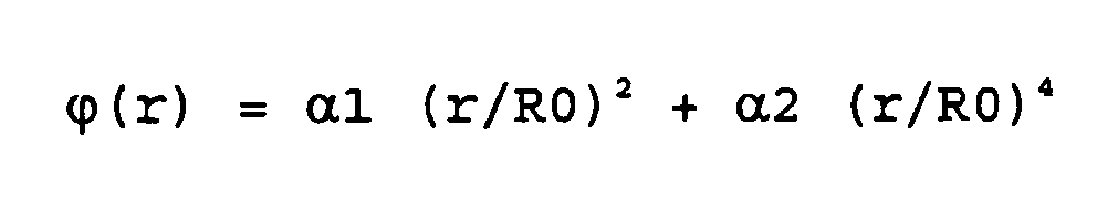
dans laquelle : - "r" est la distance par rapport au centre de la lentille d'un point considéré, se trouvant à la surface de la lentille,
- α1 et α2 sont des constantes définissant le déphasage de la surface d'onde,
- "R0" est une constante permettant de normaliser r, et "ϕ" est le déphasage introduit par la surface diffractive au point considéré.
- Les lentilles en PMMA L1, L4 et L6 sont fabriquées grâce à un procédé dit de "diamond turning" bien connu de l'homme de l'art, qui consiste à fraiser la surface des lentilles en suivant un maillage de points.
- L'angle solide de propagation des rayons lumineux dans chaque lentille est repéré sur la
figure 15 par des traits noirs. Les rayons lumineux traversent le groupe optique L1, L2, L3, passent à travers l'apodiseur L4, L5, L6, L7 tout en étant diaphragmés par D1. - La détermination des paramètres définissant les faces asphériques mentionnées ci-dessus, la formule du réseau de diffraction de la lentille L6, le calcul des diamètres des lentilles et des distances entre les lentilles, sont à la portée de l'homme de l'art en utilisant les outils classiques de conception de lentille assistée par ordinateur.
- La
figure 18 représente schématiquement un objectif 40 non linéaire utilisant un miroir déformant. L'objectif 40 comprend en entrée un groupe optique divergent constitué par exemple par les trois lentilles L1, L2, L3 décrites ci-dessus, définissant l'angle de champ de l'objectif. En regard du groupe optique se trouve un miroir plan M1 qui renvoie le faisceau lumineux sur un miroir déformant M2 de forme concave asphérique. Le faisceau réfléchi par le miroir M2 est envoyé sur un capteur d'image 43. - Dans un tel mode de réalisation, les irrégularités de sphéricité que présente la partie concave du miroir déterminent la fonction de répartition angulaire Fd recherchée pour l'application visée (déformation au centre, sur les bords...). Le résultat obtenu est équivalent à celui du système optique décrit plus haut. L'obtention de la fonction de répartition Fd est à la portée de l'homme de l'art grâce aux outils de conception de lentilles assistée par ordinateur qui permettent, outre la conception de lentilles, la conception et la mise au point de surfaces réfléchissantes.
- Une variante de ce mode de réalisation consiste à prévoir plusieurs miroirs déformants afin de combiner des déformations ou de simplifier des déformations complexes en caractérisant un type de déformation par miroir, ce qui présente l'avantage de faciliter les travaux d'ingénierie.
- Encore une autre variante consiste à utiliser un ou plusieurs miroirs déformables pour réaliser un système optique dit "adaptatif". Les miroirs déformables comprennent une couche de micro-pistons piézoélectriques couverte par une couche réfléchissante. Chaque piston piézoélectrique est activé individuellement, de sorte que l'on contrôle les déformations du miroir en plusieurs points afin d'obtenir la forme désirée. Un tel dispositif peut être piloté par un circuit intégré comprenant dans sa mémoire plusieurs configurations des micro-pistons, afin d'obtenir une fonction de répartition Fd ajustable en fonction de l'utilisation visée, ce qui évite de prévoir plusieurs objectifs.
- De façon générale, les optiques adaptatives sont en soi connues de l'homme de l'art et utilisées dans les télescopes de haute précision afin de corriger les défauts optiques des lentilles ou des déformations atmosphériques. Les miroirs déformables existent également dans le domaine des disques optiques, si l'on se réfère par exemple aux brevets
US 5 880 896 etUS 57 45 278 . - Ainsi, ici également, on utilise des moyens en soi connus à des fins différentes, non pas pour corriger une lentille mais pour obtenir au contraire une fonction de répartition angulaire non linéaire.
- La présente invention est bien entendu susceptible de diverses autres variantes de réalisation. Notamment, bien que l'on ait décrit dans ce qui précède des objectifs panoramiques non linéaires à symétrie axiale relativement à l'axe optique, dans lesquels la position d'un point image est uniquement fonction de l'angle de champ relativement à cet axe du point objet correspondant (ce qui donne une distribution de points en cercles concentriques, comme vu plus haut), il entre dans le cadre de la présente invention de prévoir des objectifs dont la non-linéarité n'est pas symétrique relativement à l'axe optique, de sorte que les parties dilatées de l'image peuvent, dans ce cas, n'être pas calées sur le centre de l'image.
-
Tableau 1 S1 - Acquisition - Prise d'une image panoramique au moyen d'un appareil photographique numérique ou d'une caméra vidéo numérique équipé(e) d'un objectif panoramique ayant fonction de répartition Fd non linéaire S2 - Transfert du fichier image dans un calculateur - Transfert du fichier image (disque image) dans un micro-ordinateur - Stockage en mémoire de masse (optionnel) S3 -Linéarisation du disque image - Transfert des points image du disque image initial dans un second disque image virtuel comprenant plus de points image que le disque image initial, au moyen de la fonction Fd-1 => Obtention d'un disque image linéaire S4 - Numérisation - Transfert des points image du second disque image dans un système d'axes OXYZ en coordonnées sphériques => Obtention d'une image panoramique en demi-sphère S5 - Affichage Interactif - Détermination des points image d'un secteur d'image à afficher - Affichage du secteur d'image sur une fenêtre d'affichage - Détection des actions de l'utilisateur sur un pointeur d'écran ou tout autre moyen de commande, - Détection des actions de l'utilisateur sur des touches de grossissement d'image, - Modification du secteur affiché (glissement du secteur d'image affiché à la surface de la demi-sphère et/ou rétrécissement/dilatation du secteur d'image affiché) Tableau 2 S1 - Acquisition - Prise d'une image panoramique au moyen d'un appareil photographique numérique ou d'une caméra vidéo numérique équipé(e) d'un objectif panoramique ayant fonction de répartition Fd non linéaire S2 - Transfert du fichier image dans un calculateur - Transfert du fichier image (disque image) dans un micro-ordinateur - Stockage en mémoire de masse (optionnel) S3' - Affichage interactif avec correction implicite de la non-linéarité de l'image initiale A - Détermination de la couleur des points E(i, j) d'un secteur d'image à afficher à partir des points p (pu, pv) du disque image : 1 - détermination des coordonnées Ex, Ey, Ez dans le repère OXYZ de chaque point E(i, j) du secteur à afficher, 2 - détermination des coordonnées Px, Py, Pz de points P de la demi-sphère correspondant aux points E(i, j), 3 - calcul des coordonnées, dans le repère O'UV du disque image, de points p (pu, pv) correspondants aux points P de la demi-sphère, au moyen de la fonction Fd, B - Présentation du secteur d'image dans une fenêtre d'affichage, C - Détection des actions de l'utilisateur sur un pointeur d'écran ou tout autre moyen de commande D - Détection des actions de l'utilisateur sur des touches de grossissement E - Modification du secteur d'image affiché (déplacement et/ou rétrécissement/grossissement du secteur d'image)
Claims (20)
- Procédé de capture d'une image panoramique numérique, par projection d'un panorama (PM) sur un capteur d'image (17) au moyen d'un objectif panoramique, dans lequel l'objectif panoramique (18, 30, 40) présente une fonction (Fd, Fd1, Fd2, Fd3) de répartition de points image (a"-d") qui n'est pas linéaire relativement à l'angle de champ de points objet (a-d) du panorama, caractérisé en ce que la fonction de répartition présente une divergence maximale d'au moins ±10% par rapport à une fonction de répartition linéaire (Fdc), et est configurée de telle sorte que l'image panoramique obtenue présente une zone (C30-C70) intermédiaire se trouvant entre le centre et le bord de l'image qui est sensiblement dilatée et deux zones (O-C30, C70-C90) se trouvant respectivement au centre de l'image et au bord de l'image qui sont sensiblement comprimées.
- Procédé selon la revendication 1, dans lequel l'objectif présente une fonction de répartition non linéaire qui est symétrique relativement à l'axe optique de l'objectif, la position d'un point image relativement au centre de l'image étant fonction de l'angle de champ du point objet correspondant.
- Procédé selon l'une des revendications 1 et 2, dans lequel l'objectif (30) comprend un jeu de lentilles (L4-L7) formant apodiseur.
- Procédé selon la revendication 3, dans lequel le jeu de lentilles formant apodiseur comprend au moins une lentille asphérique (L4, L6).
- Procédé selon la revendication 4, dans lequel le jeu de lentilles formant apodiseur comprend au moins une lentille diffractive (L6).
- Procédé selon l'une des revendications 1 à 5, dans lequel l'objectif (40) comprend un jeu de miroirs (M1, M2) comprenant au moins un miroir déformant (M2).
- Procédé d'affichage d'une image panoramique initiale (Img1) obtenue conformément au procédé selon l'une des revendications 1 à 6, caractérisé en ce qu'il comprend une étape (S3, S3') de correction de la non-linéarité de l'image initiale, faite au moyen d'une fonction (Fd-1) réciproque de la fonction (Fd) de répartition non linéaire de l'objectif ou au moyen de la fonction (Fd) de répartition non linéaire.
- Procédé selon la revendication 7, dans lequel l'étape de correction (S3) comprend une étape de transformation de l'image initiale (Img1) en une image numérique corrigée (Img1) comprenant un nombre de points image supérieur au nombre de pixels que comprend le capteur d'image (17).
- Procédé selon la revendication 8, comprenant :- une étape de calcul, au moyen de la fonction réciproque de la fonction de répartition, de la taille (R2) de l'image corrigée, de manière que l'image corrigée ait une résolution équivalente à la zone la plus dilatée de l'image initiale, et- une étape consistant à parcourir chaque point image de l'image corrigée, à chercher la position d'un point jumeau du point image sur l'image initiale et à attribuer la couleur du point jumeau au point image de l'image corrigée
- Procédé selon l'une des revendications 8 et 9, dans lequel l'image initiale et l'image corrigée comprennent un disque image (ID1, ID2).
- Procédé selon l'une des revendications 8 à 13, comprenant une étape (S4) de transfert des points image de l'image corrigée dans un espace à trois dimensions et une étape de présentation sur un moyen d'affichage d'un secteur de l'image à trois dimensions obtenue.
- Procédé selon la revendication 7, comprenant une étape (S3') de détermination de la couleur de points image d'une fenêtre d'affichage (DW), par projection des points image de la fenêtre d'affichage sur l'image initiale au moyen de la fonction de répartition non linéaire, et attribution à chaque point image de la fenêtre d'affichage de la couleur d'un point image le plus proche sur l'image initiale.
- Procédé selon la revendication 12, dans lequel la projection des points image de la fenêtre d'affichage sur l'image initiale comprend :- une étape de projection des points image de la fenêtre d'affichage sur une sphère (HS) ou une portion de sphère,- une étape de détermination de l'angle (α) par rapport au centre (O) de la sphère ou de la portion de sphère de chaque point image projeté, et- une étape de projection sur l'image initiale de chaque point image projeté sur la sphère ou la portion de sphère, la projection étant faite au moyen de la fonction de répartition non linéaire (Fd) en considérant l'angle de champ (α) que présente chaque point à projeter par rapport au centre de la sphère ou de la portion de sphère.
- Objectif panoramique (30, 40) comprenant des moyens optiques pour projeter un panorama dans un plan image de l'objectif, et présentant une fonction (Fd, Fd1, Fd2, Fd3) de répartition de points image (a"-d") qui n'est pas linéaire relativement à l'angle de champ de points objet (a-d) du panorama, la fonction de répartition présentant une divergence maximale d'au moins ±10% par rapport à une fonction de répartition linéaire (Fdc), de telle sorte qu'une image panoramique obtenue au moyen de l'objectif comprend au moins une zone (C10, C20) sensiblement dilatée et au moins une zone (C30-C90) sensiblement comprimée, caractérisé en ce que les moyens optiques sont configurés pour dilater une zone intermédiaire de l'image (C30-C70) se trouvant entre le centre et le bord de l'image, et comprimer deux zones (O-C30, C70-C90) de l'image se trouvant respectivement au centre de l'image et au bord de l'image.
- Objectif panoramique selon la revendication 14, présentant une fonction de répartition non linéaire qui est symétrique relativement à l'axe optique de l'objectif, la position d'un point image relativement au centre d'une image obtenue étant fonction de l'angle de champ du point objet correspondant.
- Objectif panoramique selon l'une des revendications 14 et 15, comprenant un jeu de lentilles (L4-L6) formant apodiseur.
- Objectif panoramique selon la revendication 16, dans lequel le jeu de lentilles formant apodiseur comprend au moins une lentille asphérique (L4, L6).
- Objectif panoramique selon l'une des revendications 16 et 17, dans lequel le jeu de lentilles formant apodiseur comprend au moins une lentille diffractive (L6).
- Objectif panoramique selon l'une des revendications 16 à 18, comprenant des lentilles en polyméthacrylate.
- Objectif panoramique selon l'une des revendications 14 et 15, comprenant un jeu de miroirs (M1, M2) comprenant au moins un miroir déformant (M2).
Applications Claiming Priority (3)
| Application Number | Priority Date | Filing Date | Title |
|---|---|---|---|
| FR0106261A FR2826221B1 (fr) | 2001-05-11 | 2001-05-11 | Procede d'obtention et d'affichage d'une image panoramique numerique a resolution variable |
| FR0106261 | 2001-05-11 | ||
| PCT/FR2002/001588 WO2002093908A2 (fr) | 2001-05-11 | 2002-05-10 | Procede de capture et d'affichage d'une image panoramique numerique a resolution variable |
Publications (2)
| Publication Number | Publication Date |
|---|---|
| EP1386480A2 EP1386480A2 (fr) | 2004-02-04 |
| EP1386480B1 true EP1386480B1 (fr) | 2011-07-20 |
Family
ID=8863182
Family Applications (1)
| Application Number | Title | Priority Date | Filing Date |
|---|---|---|---|
| EP02738233A Expired - Lifetime EP1386480B1 (fr) | 2001-05-11 | 2002-05-10 | Procede de capture et d'affichage d'une image panoramique numerique a resolution variable |
Country Status (6)
| Country | Link |
|---|---|
| US (1) | US6844990B2 (fr) |
| EP (1) | EP1386480B1 (fr) |
| AT (1) | ATE517506T1 (fr) |
| AU (1) | AU2002313045A1 (fr) |
| FR (1) | FR2826221B1 (fr) |
| WO (1) | WO2002093908A2 (fr) |
Cited By (1)
| Publication number | Priority date | Publication date | Assignee | Title |
|---|---|---|---|---|
| US9412149B2 (en) | 2011-02-10 | 2016-08-09 | Panasonic Intellectual Property Management Co., Ltd. | Display device, computer program, and computer-implemented method |
Families Citing this family (92)
| Publication number | Priority date | Publication date | Assignee | Title |
|---|---|---|---|---|
| US7382399B1 (en) | 1991-05-13 | 2008-06-03 | Sony Coporation | Omniview motionless camera orientation system |
| US8139896B1 (en) | 2005-03-28 | 2012-03-20 | Grandeye, Ltd. | Tracking moving objects accurately on a wide-angle video |
| CN101496387B (zh) * | 2006-03-06 | 2012-09-05 | 思科技术公司 | 用于移动无线网络中的接入认证的系统和方法 |
| JP5241700B2 (ja) * | 2006-03-29 | 2013-07-17 | ディジタルオプティクス・コーポレイション・ヨーロッパ・リミテッド | 画質が改良された撮像装置 |
| US7621647B1 (en) | 2006-06-23 | 2009-11-24 | The Elumenati, Llc | Optical projection system and method of use |
| KR100826571B1 (ko) | 2006-10-24 | 2008-05-07 | 주식회사 나노포토닉스 | 광각 렌즈 |
| US20080255840A1 (en) * | 2007-04-16 | 2008-10-16 | Microsoft Corporation | Video Nametags |
| US8526632B2 (en) * | 2007-06-28 | 2013-09-03 | Microsoft Corporation | Microphone array for a camera speakerphone |
| US8165416B2 (en) * | 2007-06-29 | 2012-04-24 | Microsoft Corporation | Automatic gain and exposure control using region of interest detection |
| US8330787B2 (en) | 2007-06-29 | 2012-12-11 | Microsoft Corporation | Capture device movement compensation for speaker indexing |
| US8797377B2 (en) * | 2008-02-14 | 2014-08-05 | Cisco Technology, Inc. | Method and system for videoconference configuration |
| US8355041B2 (en) * | 2008-02-14 | 2013-01-15 | Cisco Technology, Inc. | Telepresence system for 360 degree video conferencing |
| US10229389B2 (en) * | 2008-02-25 | 2019-03-12 | International Business Machines Corporation | System and method for managing community assets |
| US8016426B2 (en) * | 2008-02-27 | 2011-09-13 | 6115187 Canada Inc. | Method and device for projecting a panoramic image with a variable resolution |
| US8319819B2 (en) * | 2008-03-26 | 2012-11-27 | Cisco Technology, Inc. | Virtual round-table videoconference |
| US8390667B2 (en) * | 2008-04-15 | 2013-03-05 | Cisco Technology, Inc. | Pop-up PIP for people not in picture |
| US8694658B2 (en) * | 2008-09-19 | 2014-04-08 | Cisco Technology, Inc. | System and method for enabling communication sessions in a network environment |
| US8477175B2 (en) * | 2009-03-09 | 2013-07-02 | Cisco Technology, Inc. | System and method for providing three dimensional imaging in a network environment |
| US8659637B2 (en) * | 2009-03-09 | 2014-02-25 | Cisco Technology, Inc. | System and method for providing three dimensional video conferencing in a network environment |
| US20100283829A1 (en) * | 2009-05-11 | 2010-11-11 | Cisco Technology, Inc. | System and method for translating communications between participants in a conferencing environment |
| US8659639B2 (en) * | 2009-05-29 | 2014-02-25 | Cisco Technology, Inc. | System and method for extending communications between participants in a conferencing environment |
| US9843743B2 (en) | 2009-06-03 | 2017-12-12 | Flir Systems, Inc. | Infant monitoring systems and methods using thermal imaging |
| US9082297B2 (en) * | 2009-08-11 | 2015-07-14 | Cisco Technology, Inc. | System and method for verifying parameters in an audiovisual environment |
| US9225916B2 (en) * | 2010-03-18 | 2015-12-29 | Cisco Technology, Inc. | System and method for enhancing video images in a conferencing environment |
| US9313452B2 (en) | 2010-05-17 | 2016-04-12 | Cisco Technology, Inc. | System and method for providing retracting optics in a video conferencing environment |
| WO2012005049A1 (fr) * | 2010-07-08 | 2012-01-12 | オリンパスメディカルシステムズ株式会社 | Endoscope |
| US8896655B2 (en) | 2010-08-31 | 2014-11-25 | Cisco Technology, Inc. | System and method for providing depth adaptive video conferencing |
| US8599934B2 (en) | 2010-09-08 | 2013-12-03 | Cisco Technology, Inc. | System and method for skip coding during video conferencing in a network environment |
| FR2964818B1 (fr) | 2010-09-14 | 2012-09-28 | Thales Sa | Systeme optronique a vision supra hemispherique |
| US8599865B2 (en) | 2010-10-26 | 2013-12-03 | Cisco Technology, Inc. | System and method for provisioning flows in a mobile network environment |
| US8699457B2 (en) | 2010-11-03 | 2014-04-15 | Cisco Technology, Inc. | System and method for managing flows in a mobile network environment |
| US8902244B2 (en) | 2010-11-15 | 2014-12-02 | Cisco Technology, Inc. | System and method for providing enhanced graphics in a video environment |
| US9143725B2 (en) | 2010-11-15 | 2015-09-22 | Cisco Technology, Inc. | System and method for providing enhanced graphics in a video environment |
| US9338394B2 (en) | 2010-11-15 | 2016-05-10 | Cisco Technology, Inc. | System and method for providing enhanced audio in a video environment |
| US8730297B2 (en) | 2010-11-15 | 2014-05-20 | Cisco Technology, Inc. | System and method for providing camera functions in a video environment |
| US8542264B2 (en) | 2010-11-18 | 2013-09-24 | Cisco Technology, Inc. | System and method for managing optics in a video environment |
| US8723914B2 (en) | 2010-11-19 | 2014-05-13 | Cisco Technology, Inc. | System and method for providing enhanced video processing in a network environment |
| US9111138B2 (en) | 2010-11-30 | 2015-08-18 | Cisco Technology, Inc. | System and method for gesture interface control |
| USD678320S1 (en) | 2010-12-16 | 2013-03-19 | Cisco Technology, Inc. | Display screen with graphical user interface |
| USD678894S1 (en) | 2010-12-16 | 2013-03-26 | Cisco Technology, Inc. | Display screen with graphical user interface |
| USD682854S1 (en) | 2010-12-16 | 2013-05-21 | Cisco Technology, Inc. | Display screen for graphical user interface |
| USD682294S1 (en) | 2010-12-16 | 2013-05-14 | Cisco Technology, Inc. | Display screen with graphical user interface |
| USD678307S1 (en) | 2010-12-16 | 2013-03-19 | Cisco Technology, Inc. | Display screen with graphical user interface |
| USD678308S1 (en) | 2010-12-16 | 2013-03-19 | Cisco Technology, Inc. | Display screen with graphical user interface |
| USD682864S1 (en) | 2010-12-16 | 2013-05-21 | Cisco Technology, Inc. | Display screen with graphical user interface |
| USD682293S1 (en) | 2010-12-16 | 2013-05-14 | Cisco Technology, Inc. | Display screen with graphical user interface |
| US8692862B2 (en) | 2011-02-28 | 2014-04-08 | Cisco Technology, Inc. | System and method for selection of video data in a video conference environment |
| US8670019B2 (en) | 2011-04-28 | 2014-03-11 | Cisco Technology, Inc. | System and method for providing enhanced eye gaze in a video conferencing environment |
| US8786631B1 (en) | 2011-04-30 | 2014-07-22 | Cisco Technology, Inc. | System and method for transferring transparency information in a video environment |
| US8934026B2 (en) | 2011-05-12 | 2015-01-13 | Cisco Technology, Inc. | System and method for video coding in a dynamic environment |
| EP2554434B1 (fr) * | 2011-08-05 | 2014-05-21 | Harman Becker Automotive Systems GmbH | Système de visualisation panoramique de véhicule |
| US8947493B2 (en) | 2011-11-16 | 2015-02-03 | Cisco Technology, Inc. | System and method for alerting a participant in a video conference |
| US8682087B2 (en) | 2011-12-19 | 2014-03-25 | Cisco Technology, Inc. | System and method for depth-guided image filtering in a video conference environment |
| KR102306729B1 (ko) | 2012-04-05 | 2021-09-28 | 매직 립, 인코포레이티드 | 능동 포비에이션 능력을 갖는 와이드-fov(field of view) 이미지 디바이스들 |
| JP2015530655A (ja) * | 2012-08-30 | 2015-10-15 | オセ−テクノロジーズ・ベー・ヴエーOce’−Nederland Besloten Vennootshap | 極端なアスペクト比/デジタル画像を表示するためのユーザインタフェースを有する印刷システム |
| US9681154B2 (en) | 2012-12-06 | 2017-06-13 | Patent Capital Group | System and method for depth-guided filtering in a video conference environment |
| US9843621B2 (en) | 2013-05-17 | 2017-12-12 | Cisco Technology, Inc. | Calendaring activities based on communication processing |
| US20140372265A1 (en) * | 2013-06-14 | 2014-12-18 | Microsoft Corporation | User experience for capturing timesheet items |
| US9363638B1 (en) | 2015-06-02 | 2016-06-07 | GeoFrenzy, Inc. | Registrar mapping toolkit for geofences |
| US9906609B2 (en) | 2015-06-02 | 2018-02-27 | GeoFrenzy, Inc. | Geofence information delivery systems and methods |
| US9906902B2 (en) | 2015-06-02 | 2018-02-27 | GeoFrenzy, Inc. | Geofence information delivery systems and methods |
| US10121215B2 (en) | 2014-07-29 | 2018-11-06 | GeoFrenzy, Inc. | Systems and methods for managing real estate titles and permissions |
| US10235726B2 (en) | 2013-09-24 | 2019-03-19 | GeoFrenzy, Inc. | Systems and methods for secure encryption of real estate titles and permissions |
| US9973692B2 (en) | 2013-10-03 | 2018-05-15 | Flir Systems, Inc. | Situational awareness by compressed display of panoramic views |
| FR3015696B1 (fr) * | 2013-12-20 | 2016-02-05 | Thales Sa | Module optique d'imagerie a champ hyper hemispherique et distorsion controlee, compatible d'un environnement exterieur |
| US9786016B2 (en) | 2014-02-28 | 2017-10-10 | Microsoft Technology Licensing, Llc | Image tagging for capturing information in a transaction |
| KR102357290B1 (ko) | 2014-03-25 | 2022-01-28 | 임머비젼, 인코퍼레이티드 | 광각 이미지와 관련된 정보를 기록, 공유 및 처리함으로써 사용자 경험 또는 시스템 가동의 자동 정의 |
| US11606666B2 (en) | 2014-07-29 | 2023-03-14 | GeoFrenzy, Inc. | Global registration system for aerial vehicles |
| US10805761B2 (en) | 2014-07-29 | 2020-10-13 | GeoFrenzy, Inc. | Global registration system for aerial vehicles |
| US10375514B2 (en) | 2014-07-29 | 2019-08-06 | GeoFrenzy, Inc. | Systems, methods and apparatus for geofence networks |
| US10582333B2 (en) | 2014-07-29 | 2020-03-03 | GeoFrenzy, Inc. | Systems and methods for geofence security |
| US9875251B2 (en) | 2015-06-02 | 2018-01-23 | GeoFrenzy, Inc. | Geofence information delivery systems and methods |
| US10115277B2 (en) | 2014-07-29 | 2018-10-30 | GeoFrenzy, Inc. | Systems and methods for geofence security |
| US12022352B2 (en) | 2014-07-29 | 2024-06-25 | GeoFrenzy, Inc. | Systems, methods and apparatus for geofence networks |
| US11240628B2 (en) | 2014-07-29 | 2022-02-01 | GeoFrenzy, Inc. | Systems and methods for decoupling and delivering geofence geometries to maps |
| US10979849B2 (en) | 2015-06-02 | 2021-04-13 | GeoFrenzy, Inc. | Systems, methods and apparatus for geofence networks |
| US11838744B2 (en) | 2014-07-29 | 2023-12-05 | GeoFrenzy, Inc. | Systems, methods and apparatus for geofence networks |
| US9986378B2 (en) | 2014-07-29 | 2018-05-29 | GeoFrenzy, Inc. | Systems and methods for defining and implementing rules for three dimensional geofences |
| US10237232B2 (en) | 2014-07-29 | 2019-03-19 | GeoFrenzy, Inc. | Geocoding with geofences |
| US10932084B2 (en) | 2014-07-29 | 2021-02-23 | GeoFrenzy, Inc. | Systems, methods and apparatus for geofence networks |
| WO2016196496A1 (fr) | 2015-06-02 | 2016-12-08 | GeoFrenzy, Inc. | Systèmes et procédés de fourniture d'informations de barrières géographiques |
| US10694249B2 (en) | 2015-09-09 | 2020-06-23 | Vantrix Corporation | Method and system for selective content processing based on a panoramic camera and a virtual-reality headset |
| US11287653B2 (en) | 2015-09-09 | 2022-03-29 | Vantrix Corporation | Method and system for selective content processing based on a panoramic camera and a virtual-reality headset |
| US10506006B2 (en) | 2015-09-09 | 2019-12-10 | Vantrix Corporation | Method and system for flow-rate regulation in a content-controlled streaming network |
| US11108670B2 (en) | 2015-09-09 | 2021-08-31 | Vantrix Corporation | Streaming network adapted to content selection |
| US10419770B2 (en) | 2015-09-09 | 2019-09-17 | Vantrix Corporation | Method and system for panoramic multimedia streaming |
| US10353173B2 (en) * | 2015-12-23 | 2019-07-16 | 6115187 Canada, Inc. | Miniature wide-angle imaging lens |
| CN109074632B (zh) | 2016-02-16 | 2022-03-01 | 6115187加拿大公司暨伊美景象公司 | 图像失真变换方法和设备 |
| US10951859B2 (en) | 2018-05-30 | 2021-03-16 | Microsoft Technology Licensing, Llc | Videoconferencing device and method |
| US11513346B2 (en) * | 2019-05-24 | 2022-11-29 | Beijing Boe Optoelectronics Technology Co., Ltd. | Method and apparatus for controlling virtual reality display device |
| EP4009622B1 (fr) | 2020-12-01 | 2024-04-03 | Continental Autonomous Mobility Germany GmbH | Procédé de capture et de traitement d'une image panoramique numérique |
| TWI793702B (zh) * | 2021-08-05 | 2023-02-21 | 明志科技大學 | 求取相機的光學投射機制的方法 |
Family Cites Families (10)
| Publication number | Priority date | Publication date | Assignee | Title |
|---|---|---|---|---|
| US3953111A (en) * | 1974-11-04 | 1976-04-27 | Mcdonnell Douglas Corporation | Non-linear lens |
| US6031670A (en) * | 1990-08-28 | 2000-02-29 | Sankyo Seiki Mfg. Co., Ltd. | Wide-angle lens |
| US5508734A (en) * | 1994-07-27 | 1996-04-16 | International Business Machines Corporation | Method and apparatus for hemispheric imaging which emphasizes peripheral content |
| US5710661A (en) | 1996-06-27 | 1998-01-20 | Hughes Electronics | Integrated panoramic and high resolution sensor optics |
| JP3420894B2 (ja) * | 1996-08-09 | 2003-06-30 | シャープ株式会社 | 変形可能ミラー |
| US5745278A (en) | 1997-02-05 | 1998-04-28 | Raytheon Optical Systems, Inc. | Innovative deformable mirror actuator configuration |
| US6449103B1 (en) * | 1997-04-16 | 2002-09-10 | Jeffrey R. Charles | Solid catadioptric omnidirectional optical system having central coverage means which is associated with a camera, projector, medical instrument, or similar article |
| US6333826B1 (en) * | 1997-04-16 | 2001-12-25 | Jeffrey R. Charles | Omniramic optical system having central coverage means which is associated with a camera, projector, or similar article |
| US6128145A (en) * | 1998-11-25 | 2000-10-03 | Fit Corporation | Image pick-up device, image display device and information recording medium comprising a fisheye lens |
| AUPP819199A0 (en) * | 1999-01-15 | 1999-02-11 | Australian National University, The | Resolution invariant panoramic imaging |
-
2001
- 2001-05-11 FR FR0106261A patent/FR2826221B1/fr not_active Expired - Fee Related
-
2002
- 2002-05-10 WO PCT/FR2002/001588 patent/WO2002093908A2/fr not_active Application Discontinuation
- 2002-05-10 AU AU2002313045A patent/AU2002313045A1/en not_active Abandoned
- 2002-05-10 EP EP02738233A patent/EP1386480B1/fr not_active Expired - Lifetime
- 2002-05-10 AT AT02738233T patent/ATE517506T1/de not_active IP Right Cessation
-
2003
- 2003-11-12 US US10/706,513 patent/US6844990B2/en not_active Expired - Lifetime
Cited By (2)
| Publication number | Priority date | Publication date | Assignee | Title |
|---|---|---|---|---|
| US9412149B2 (en) | 2011-02-10 | 2016-08-09 | Panasonic Intellectual Property Management Co., Ltd. | Display device, computer program, and computer-implemented method |
| US11651471B2 (en) | 2011-02-10 | 2023-05-16 | Panasonic Intellectual Property Management Co., Ltd. | Display device, computer program, and computer-implemented method |
Also Published As
| Publication number | Publication date |
|---|---|
| US20040136092A1 (en) | 2004-07-15 |
| US6844990B2 (en) | 2005-01-18 |
| EP1386480A2 (fr) | 2004-02-04 |
| WO2002093908A3 (fr) | 2003-02-27 |
| AU2002313045A1 (en) | 2002-11-25 |
| FR2826221B1 (fr) | 2003-12-05 |
| FR2826221A1 (fr) | 2002-12-20 |
| WO2002093908A2 (fr) | 2002-11-21 |
| ATE517506T1 (de) | 2011-08-15 |
Similar Documents
| Publication | Publication Date | Title |
|---|---|---|
| EP1386480B1 (fr) | Procede de capture et d'affichage d'une image panoramique numerique a resolution variable | |
| EP1421442B1 (fr) | Procede de capture d'une image panoramique au moyen d'un capteur d'image de forme rectangulaire | |
| Peng et al. | Learned large field-of-view imaging with thin-plate optics. | |
| Tseng et al. | Differentiable compound optics and processing pipeline optimization for end-to-end camera design | |
| US8441732B2 (en) | Whole beam image splitting system | |
| EP2191322B1 (fr) | Procédé d'accroissement de la profondeur de champ d'un système optique | |
| EP3086185A1 (fr) | Système et procédé d'affichage tridimensionnel holographique | |
| FR2955673A1 (fr) | Dispositif de projection courte distance raisonnablement grand angle avec zoom et mise au point | |
| EP1713017A1 (fr) | Procédé, dispositif et caméra pour la détection d'objets à partir d'images numériques | |
| FR3087275A1 (fr) | Systeme de saisie de l'environnement d'un vehicule et procede de mise en œuvre | |
| CN107421640B (zh) | 基于色差扩大原理的多光谱光场成像系统及方法 | |
| US20230292016A1 (en) | Meta-lens enabled light-field camera with extreme depth-of-field | |
| CA2701151A1 (fr) | Systeme d'imagerie a modification de front d'onde et procede d'augmentation de la profondeur de champ d'un systeme d'imagerie | |
| Saragadam et al. | Foveated thermal computational imaging in the wild using all-silicon meta-optics | |
| EP4111499A1 (fr) | Ecran d'affichage à résolution multiple et procédé de réalisation | |
| JP2004518158A (ja) | 疑似ランダム化されたぼかされた赤外線画像形成素子アレイ | |
| Brückner et al. | Driving micro-optical imaging systems towards miniature camera applications | |
| Sun | End-to-end Optics Design for Computational Cameras | |
| EP4130867B1 (fr) | Procede d'acquisition d'image d'au moins un astre et appareil pour la mise en oeuvre du procede | |
| JP2024504261A (ja) | 部分反射器を活用する高倍率写真撮影における像補正及び処理のための方法及びシステム | |
| Pang | Optical Design For Parallel Cameras | |
| WO2016053140A1 (fr) | Dispositif mobile avec éléments optiques | |
| Pang et al. | Thin Lenses and Thin Cameras | |
| WO2024083580A1 (fr) | Appareils et procédés pour spectrométrie d'imagerie par tomodensitométrie | |
| FR2973892A1 (fr) | Systeme de conduite infrarouge stereoscopique a profondeur de champ augmentee |
Legal Events
| Date | Code | Title | Description |
|---|---|---|---|
| PUAI | Public reference made under article 153(3) epc to a published international application that has entered the european phase |
Free format text: ORIGINAL CODE: 0009012 |
|
| 17P | Request for examination filed |
Effective date: 20031117 |
|
| AK | Designated contracting states |
Kind code of ref document: A2 Designated state(s): AT BE CH CY DE DK ES FI FR GB GR IE IT LI LU MC NL PT SE TR |
|
| AX | Request for extension of the european patent |
Extension state: AL LT LV MK RO SI |
|
| 17Q | First examination report despatched |
Effective date: 20090525 |
|
| GRAP | Despatch of communication of intention to grant a patent |
Free format text: ORIGINAL CODE: EPIDOSNIGR1 |
|
| RIN1 | Information on inventor provided before grant (corrected) |
Inventor name: BLANC, BENJAMIN Inventor name: MOUSTIER, CHRISTOPHE Inventor name: ARTONNE, JEAN-CLAUDE |
|
| GRAS | Grant fee paid |
Free format text: ORIGINAL CODE: EPIDOSNIGR3 |
|
| GRAA | (expected) grant |
Free format text: ORIGINAL CODE: 0009210 |
|
| AK | Designated contracting states |
Kind code of ref document: B1 Designated state(s): AT BE CH CY DE DK ES FI FR GB GR IE IT LI LU MC NL PT SE TR |
|
| REG | Reference to a national code |
Ref country code: GB Ref legal event code: FG4D Free format text: NOT ENGLISH |
|
| REG | Reference to a national code |
Ref country code: CH Ref legal event code: EP |
|
| REG | Reference to a national code |
Ref country code: DE Ref legal event code: R096 Ref document number: 60240559 Country of ref document: DE Effective date: 20110908 |
|
| REG | Reference to a national code |
Ref country code: NL Ref legal event code: VDEP Effective date: 20110720 |
|
| REG | Reference to a national code |
Ref country code: AT Ref legal event code: MK05 Ref document number: 517506 Country of ref document: AT Kind code of ref document: T Effective date: 20110720 |
|
| PG25 | Lapsed in a contracting state [announced via postgrant information from national office to epo] |
Ref country code: SE Free format text: LAPSE BECAUSE OF FAILURE TO SUBMIT A TRANSLATION OF THE DESCRIPTION OR TO PAY THE FEE WITHIN THE PRESCRIBED TIME-LIMIT Effective date: 20110720 Ref country code: PT Free format text: LAPSE BECAUSE OF FAILURE TO SUBMIT A TRANSLATION OF THE DESCRIPTION OR TO PAY THE FEE WITHIN THE PRESCRIBED TIME-LIMIT Effective date: 20111121 Ref country code: NL Free format text: LAPSE BECAUSE OF FAILURE TO SUBMIT A TRANSLATION OF THE DESCRIPTION OR TO PAY THE FEE WITHIN THE PRESCRIBED TIME-LIMIT Effective date: 20110720 Ref country code: FI Free format text: LAPSE BECAUSE OF FAILURE TO SUBMIT A TRANSLATION OF THE DESCRIPTION OR TO PAY THE FEE WITHIN THE PRESCRIBED TIME-LIMIT Effective date: 20110720 |
|
| REG | Reference to a national code |
Ref country code: IE Ref legal event code: FD4D |
|
| PG25 | Lapsed in a contracting state [announced via postgrant information from national office to epo] |
Ref country code: CY Free format text: LAPSE BECAUSE OF FAILURE TO SUBMIT A TRANSLATION OF THE DESCRIPTION OR TO PAY THE FEE WITHIN THE PRESCRIBED TIME-LIMIT Effective date: 20110720 Ref country code: AT Free format text: LAPSE BECAUSE OF FAILURE TO SUBMIT A TRANSLATION OF THE DESCRIPTION OR TO PAY THE FEE WITHIN THE PRESCRIBED TIME-LIMIT Effective date: 20110720 Ref country code: GR Free format text: LAPSE BECAUSE OF FAILURE TO SUBMIT A TRANSLATION OF THE DESCRIPTION OR TO PAY THE FEE WITHIN THE PRESCRIBED TIME-LIMIT Effective date: 20111021 |
|
| PG25 | Lapsed in a contracting state [announced via postgrant information from national office to epo] |
Ref country code: IE Free format text: LAPSE BECAUSE OF FAILURE TO SUBMIT A TRANSLATION OF THE DESCRIPTION OR TO PAY THE FEE WITHIN THE PRESCRIBED TIME-LIMIT Effective date: 20110720 |
|
| PLBE | No opposition filed within time limit |
Free format text: ORIGINAL CODE: 0009261 |
|
| STAA | Information on the status of an ep patent application or granted ep patent |
Free format text: STATUS: NO OPPOSITION FILED WITHIN TIME LIMIT |
|
| PG25 | Lapsed in a contracting state [announced via postgrant information from national office to epo] |
Ref country code: IT Free format text: LAPSE BECAUSE OF FAILURE TO SUBMIT A TRANSLATION OF THE DESCRIPTION OR TO PAY THE FEE WITHIN THE PRESCRIBED TIME-LIMIT Effective date: 20110720 |
|
| 26N | No opposition filed |
Effective date: 20120423 |
|
| PG25 | Lapsed in a contracting state [announced via postgrant information from national office to epo] |
Ref country code: DK Free format text: LAPSE BECAUSE OF FAILURE TO SUBMIT A TRANSLATION OF THE DESCRIPTION OR TO PAY THE FEE WITHIN THE PRESCRIBED TIME-LIMIT Effective date: 20110720 |
|
| REG | Reference to a national code |
Ref country code: DE Ref legal event code: R097 Ref document number: 60240559 Country of ref document: DE Effective date: 20120423 |
|
| BERE | Be: lapsed |
Owner name: 6115187 CANADA INC. Effective date: 20120531 |
|
| PG25 | Lapsed in a contracting state [announced via postgrant information from national office to epo] |
Ref country code: MC Free format text: LAPSE BECAUSE OF NON-PAYMENT OF DUE FEES Effective date: 20120531 |
|
| REG | Reference to a national code |
Ref country code: CH Ref legal event code: PL |
|
| PG25 | Lapsed in a contracting state [announced via postgrant information from national office to epo] |
Ref country code: LI Free format text: LAPSE BECAUSE OF NON-PAYMENT OF DUE FEES Effective date: 20120531 Ref country code: CH Free format text: LAPSE BECAUSE OF NON-PAYMENT OF DUE FEES Effective date: 20120531 |
|
| PG25 | Lapsed in a contracting state [announced via postgrant information from national office to epo] |
Ref country code: BE Free format text: LAPSE BECAUSE OF NON-PAYMENT OF DUE FEES Effective date: 20120531 |
|
| PG25 | Lapsed in a contracting state [announced via postgrant information from national office to epo] |
Ref country code: ES Free format text: LAPSE BECAUSE OF FAILURE TO SUBMIT A TRANSLATION OF THE DESCRIPTION OR TO PAY THE FEE WITHIN THE PRESCRIBED TIME-LIMIT Effective date: 20111031 |
|
| PG25 | Lapsed in a contracting state [announced via postgrant information from national office to epo] |
Ref country code: TR Free format text: LAPSE BECAUSE OF FAILURE TO SUBMIT A TRANSLATION OF THE DESCRIPTION OR TO PAY THE FEE WITHIN THE PRESCRIBED TIME-LIMIT Effective date: 20110720 |
|
| PG25 | Lapsed in a contracting state [announced via postgrant information from national office to epo] |
Ref country code: LU Free format text: LAPSE BECAUSE OF NON-PAYMENT OF DUE FEES Effective date: 20120510 |
|
| REG | Reference to a national code |
Ref country code: FR Ref legal event code: PLFP Year of fee payment: 15 |
|
| REG | Reference to a national code |
Ref country code: FR Ref legal event code: PLFP Year of fee payment: 16 |
|
| REG | Reference to a national code |
Ref country code: FR Ref legal event code: PLFP Year of fee payment: 17 |
|
| PGFP | Annual fee paid to national office [announced via postgrant information from national office to epo] |
Ref country code: DE Payment date: 20210421 Year of fee payment: 20 Ref country code: FR Payment date: 20210518 Year of fee payment: 20 |
|
| PGFP | Annual fee paid to national office [announced via postgrant information from national office to epo] |
Ref country code: GB Payment date: 20210422 Year of fee payment: 20 |
|
| REG | Reference to a national code |
Ref country code: DE Ref legal event code: R071 Ref document number: 60240559 Country of ref document: DE |
|
| REG | Reference to a national code |
Ref country code: GB Ref legal event code: PE20 Expiry date: 20220509 |
|
| PG25 | Lapsed in a contracting state [announced via postgrant information from national office to epo] |
Ref country code: GB Free format text: LAPSE BECAUSE OF EXPIRATION OF PROTECTION Effective date: 20220509 |