EP1386044B1 - Hook holder for holding scaffolding elements to a scaffold - Google Patents
Hook holder for holding scaffolding elements to a scaffold Download PDFInfo
- Publication number
- EP1386044B1 EP1386044B1 EP02724843A EP02724843A EP1386044B1 EP 1386044 B1 EP1386044 B1 EP 1386044B1 EP 02724843 A EP02724843 A EP 02724843A EP 02724843 A EP02724843 A EP 02724843A EP 1386044 B1 EP1386044 B1 EP 1386044B1
- Authority
- EP
- European Patent Office
- Prior art keywords
- holding
- holding part
- pivoted
- blocking
- scaffold
- Prior art date
- Legal status (The legal status is an assumption and is not a legal conclusion. Google has not performed a legal analysis and makes no representation as to the accuracy of the status listed.)
- Expired - Lifetime
Links
- 230000000903 blocking effect Effects 0.000 claims abstract description 32
- 238000006073 displacement reaction Methods 0.000 claims abstract description 9
- 230000000717 retained effect Effects 0.000 description 8
- 230000006835 compression Effects 0.000 description 5
- 238000007906 compression Methods 0.000 description 5
- 238000010276 construction Methods 0.000 description 1
- 230000000630 rising effect Effects 0.000 description 1
- 238000003466 welding Methods 0.000 description 1
Images


Classifications
-
- E—FIXED CONSTRUCTIONS
- E04—BUILDING
- E04G—SCAFFOLDING; FORMS; SHUTTERING; BUILDING IMPLEMENTS OR AIDS, OR THEIR USE; HANDLING BUILDING MATERIALS ON THE SITE; REPAIRING, BREAKING-UP OR OTHER WORK ON EXISTING BUILDINGS
- E04G7/00—Connections between parts of the scaffold
- E04G7/02—Connections between parts of the scaffold with separate coupling elements
- E04G7/28—Clips or connections for securing boards
-
- E—FIXED CONSTRUCTIONS
- E04—BUILDING
- E04G—SCAFFOLDING; FORMS; SHUTTERING; BUILDING IMPLEMENTS OR AIDS, OR THEIR USE; HANDLING BUILDING MATERIALS ON THE SITE; REPAIRING, BREAKING-UP OR OTHER WORK ON EXISTING BUILDINGS
- E04G1/00—Scaffolds primarily resting on the ground
- E04G1/15—Scaffolds primarily resting on the ground essentially comprising special means for supporting or forming platforms; Platforms
-
- E—FIXED CONSTRUCTIONS
- E04—BUILDING
- E04G—SCAFFOLDING; FORMS; SHUTTERING; BUILDING IMPLEMENTS OR AIDS, OR THEIR USE; HANDLING BUILDING MATERIALS ON THE SITE; REPAIRING, BREAKING-UP OR OTHER WORK ON EXISTING BUILDINGS
- E04G5/00—Component parts or accessories for scaffolds
-
- E—FIXED CONSTRUCTIONS
- E04—BUILDING
- E04G—SCAFFOLDING; FORMS; SHUTTERING; BUILDING IMPLEMENTS OR AIDS, OR THEIR USE; HANDLING BUILDING MATERIALS ON THE SITE; REPAIRING, BREAKING-UP OR OTHER WORK ON EXISTING BUILDINGS
- E04G5/00—Component parts or accessories for scaffolds
- E04G5/14—Railings
- E04G5/145—Toe boards therefor
-
- E—FIXED CONSTRUCTIONS
- E04—BUILDING
- E04G—SCAFFOLDING; FORMS; SHUTTERING; BUILDING IMPLEMENTS OR AIDS, OR THEIR USE; HANDLING BUILDING MATERIALS ON THE SITE; REPAIRING, BREAKING-UP OR OTHER WORK ON EXISTING BUILDINGS
- E04G1/00—Scaffolds primarily resting on the ground
- E04G1/15—Scaffolds primarily resting on the ground essentially comprising special means for supporting or forming platforms; Platforms
- E04G2001/156—Stackable platforms
Definitions
- a spring mechanism 14 is arranged, that in the example shown is in the form of a helical spring that forms a compression spring that is preloaded between one of the gable parts 7 and the axial casing 10 and thus strives to retain the pivoted part 11 axially displaced in such a way that the axis casing bears on the inside of the gable part 8.
- a recess 15 is arranged in the base part 5, more precisely in one of its edges 16.
- the holding hook according to the invention is easily shifted from a transporting position according to Fig. 1 and 2 to an open, releasing or not blocking position by a person grabbing hold of the pivoting part 11 and bringing it a distance against the load of the compression spring 14 such that the blocking part 13 ends up in front of the opening 18, after which the pivoted part is free to be risen to the position shown in Fig. 3 and 4 .
- the compression ring 14 strives to retain the blocking part 13 against one of the edges 21 of the opening 18. In this way the pivoted part 11 may be retained in an open position by means of friction against the edge 21 of one of the side surfaces 22 of the pivoted part.
- the purpose with the present invention is thus not to accomplish a rigid locking between two scaffold elements, but a retaining of position primarily viewed in one plane.
Landscapes
- Engineering & Computer Science (AREA)
- Architecture (AREA)
- Mechanical Engineering (AREA)
- Civil Engineering (AREA)
- Structural Engineering (AREA)
- Hooks, Suction Cups, And Attachment By Adhesive Means (AREA)
- Mutual Connection Of Rods And Tubes (AREA)
- Electric Cable Installation (AREA)
- Emergency Lowering Means (AREA)
- Supports Or Holders For Household Use (AREA)
Abstract
Description
- The present invention relates to a retaining hook according to the preamble of appended claim 1.
- Previously known retaining hooks for blocking a retained position for different scaffold elements at a scaffold normally consists of a hook with a bolt that is displaceable between a blocking position and a releasing position. It must then be verified that the bolt is retained in a blocking position without risk for an unintentional shift. For this purpose, the bolt has to be mounted with well balanced friction or be equipped with a safety lock. Previously known solutions have been relatively expensive, since small tolerances are required and sometimes several movable arts.
- Prior art is disclosed in the documents
US-A-2 811 395 andWO-A-94/23153 - The purpose of the present invention is to present a retaining hook that has an extraordinarily simple construction and which thus is easy to handle, but nevertheless is reliably blocked in the blocking position. Said purpose is achieved by means of retaining hook according to the invention, which characterising features are evident from the appended claim 1.
- The invention will in the following be described more in detail with an embodiment example with reference to the enclosed drawings, where:
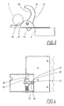
- Fig. 1 and 2
- show the retaining hook in a transporting condition in two different views,
- Fig. 3 and 4
- show the retaining hook in a releasing position,
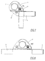
- Fig. 5 and 6
- show the retaining hook in a blocked holding position,
- Fig. 7, 8 and 9
- show the retaining hook in different mounting cases, while
- Fig. 10
- shows how the retaining hook may be piled for transport.
- As disclosed in
fig. 1-6 , the retaining hook 1 according to the invention consists of arigid part 2, that is firmly applied to ascaffold element 4 by means of a mounting plate 3, whichscaffold element 4 is a first type that shall be retained in position at ascaffold element 5 of the second type. Ascaffold element 4, may by way of example, be a deal standing on end or a border that is coupled to the posts, for example at the bottom of the scaffold in order to secure the positions of the pole where they rest on a foundation. Alternatively, a scaffold element of the first type may be a work platform that extends between horizontal scaffold tubes in a scaffold. The scaffold element of the second type is thus eithervertical posts 5 in a scaffold or horizontal scaffold tubes that extend between posts in a scaffold. Thefixed part 2 comprises aconsole 6 with abase part 30, which is rigidly connected to the mounting plate 3, for example by means of welding, and twogable parts pivoting axis 9 extends, which is mounted in the gable parts in its ends and forms bearing for anaxis casing 10. On this a pivoted part is applied, which thus is pivotally applied on theaxis 9 and thus relative to thefixed part 2. Thepivoted part 11 is in the example shown shaped as a hook with afree hook end 12 and a blockingpart 13 placed on the opposite side. Alternatively, theaxial casing 10 may be rigidly applied on theaxis 9, which thus is pivotally (and axially displaceably) carried in holes in thegable parts - Except the fact that the
pivoted part 11 is pivoted around itsaxis 9, it is axially displaceable along the axis or at least a part of the length of the axis. Further, aspring mechanism 14 is arranged, that in the example shown is in the form of a helical spring that forms a compression spring that is preloaded between one of thegable parts 7 and theaxial casing 10 and thus strives to retain thepivoted part 11 axially displaced in such a way that the axis casing bears on the inside of thegable part 8. Further, arecess 15 is arranged in thebase part 5, more precisely in one of itsedges 16. This recess is placed and dimensioned to receive theend 12 of thepivoted part 11 such that the whole retaining hook has a minimum height in the transporting position according toFig. 1 and 2 . In this position the backwards, upwards facingpart 17 of the pivoted part that in the example shown is relatively straight, is positioned mainly parallel to the mounting plate 3. - Further, an
opening 18 is arranged in thepermanent part 2, which opening 18 is arranged to allow rising of thepivoted part 11 to a releasing, not blocked position, by receiving the blockingpart 13 of the pivoted part, seeFig. 3 and 4 . For this purpose, theopening 18 is at least somewhat wider than the width of thepivoted part 11 and placed in the vicinity of theaxis 9. Further, theopening 18 is longish and extends parallel to thegable parts axis 8. Further, the holding hook according to the invention is equipped with two fixedholding surfaces 19 or edges applied on thegable parts movable holding surface 20 or edge, applied on the inside of the pivoted part. Theholding surfaces scaffold element 5 that is going to be retained, in the example shown an arc-shaped profile shape. The holding surfaces are thus preferably arc-shaped. - The holding hook according to the invention is easily shifted from a transporting position according to
Fig. 1 and 2 to an open, releasing or not blocking position by a person grabbing hold of thepivoting part 11 and bringing it a distance against the load of thecompression spring 14 such that the blockingpart 13 ends up in front of the opening 18, after which the pivoted part is free to be risen to the position shown inFig. 3 and 4 . When one lets go of thepivoted part 11, thecompression ring 14 strives to retain the blockingpart 13 against one of theedges 21 of the opening 18. In this way thepivoted part 11 may be retained in an open position by means of friction against theedge 21 of one of theside surfaces 22 of the pivoted part. By means of a side-wards directed protrusion (not shown) or extra high friction in theside surface 22 the opened position may be further secured. Thus the holding hook may be brought forward towards thatscaffold element 5 at which thescaffold element 4 shall be held. Theelement 5 bears on theholding surfaces 19 with itssurface 23, after which thepivoted part 11 may be lowered by pressing the outside 24 of the pivoted part with the hand. - When the blocking
part 13 of the pivoted part is risen from theopening 18, allowing the part with itssurface 21 to be brought out of contact with theedge 22 of the opening, that pivoted part will be displaced along itspivot axis 9 under the load of thecompressions spring 14. A displacement movement is stopped by means of the impact of theend surface 24 of theaxial casing 10 against the inside of thegable part 8, seeFig. 6 . As the spring force of thecompression spring 14 is adapted to keep thepivoted part 11 in this displacement position, the holder block will be blocked as the blockingpart 13 is blocked against the upwards facing blockingsurface 27 of thebase part 5 between thehole 18 and thegable part 8, with a blockingedge 26. By means of optimum dimensioning, the blockingedge 26 is in contact with the blockingsurface 27 at a certain uniform diameter of thescaffold element 5, but in practise such tolerances are chosen that a certain play is allowed. Thescaffold element 5 is retained in its position when the condition is met that the opening 28 between thehook end 12 and theholding surface 19 of thefixed part 2 falls below the transverse dimension or outer diameter of theelement 5. A piece of thegable part 6 has been broken away inFig. 5 in order to visualise the blocking function. In the example shown, the basic part and the mounting plate 3 are overlapping in the area at the blockingsurface 27 and thus extra reinforced. - The purpose with the present invention is thus not to accomplish a rigid locking between two scaffold elements, but a retaining of position primarily viewed in one plane.
- Inversely, the holding hook is easily shifted to a releasing position, by manually catching hold of the
pivoting part 11, and bringing it in a direction from the blocking holding position shown inFig. 5 and 6 until the pivoted part actually ends up in front of theopening 18 along theaxis 9. In this position the pivoted part is free to be raised as the blocking part is allowed to be lowered in the opening 18 and may be retained in an opening position according toFig. 3 and 4 in the manner described above. The scaffold elements are thus free to be separated from each other. -
Fig. 7 shows how twoscaffold elements 4 may be retained in a position to thescaffold element 5 of the other type, where it is verified that the holding hooks are mutually displaced relative to the longitudinal axis of thescaffold element 5, more precisely with a displacement of the width of the console. InFig. 7 the twoscaffold elements 4 are shown arranged at right angles to each other, i.e. 90° to each other, with thescaffold element 5 outside the corner.Fig. 8 shows the two scaffold elements aligned with each other, i.e. with 180° angle whileFig. 9 shows thescaffold elements 4 at right angles to each other with thescaffold element 5 inside the formed corner i.e. with 270° angle. - With the holding hook in transporting position according to
Fig. 1 and 2 , thescaffold elements 4 may be piled on each other, as disclosed inFig. 10 , without the holding hooks increasing the height during piling. - The invention is not limited to the embodiments that are described above and shown on the drawings, but may be varied within the scope of the appended claims. For example, it is conceivable that the fixed part, i.e. the console, is arranged in a hook-shaped way, while the pivoted part may be principally straight, possibly hook-shaped. The permanent part may here preferably be placed above the
scaffold element 5, for example when horizontal scaffold elements are used for mounting, where thescaffold elements 4 may be work platforms. Only one end of thescaffold element 4 is shown. The opposite end is also suitably equipped with the holding hook according to the invention. At large widths, two or more holding hooks may be mounted at each end. With theaxis 9 in the claims, the geometrical axis is concerned since the physical axis may (in an alternative embodiment) follow the movements of the hook.
Claims (4)
- Holding hook for mutual blocking position retaining of a first type of a scaffold elements (4) at a second type of scaffold elements (5) in a scaffold and consisting of a holding part (11) that relative to an axis (9) is pivotally applied to a fixed holding part (2), which pivotally applied holding part (11) is shiftable between a holding position in which the pivoted holding part is blocked and a releasing position for the scaffold elements, characterized in that the holding hook (1) is arranged to also be axially displaceable along the axis (9) relative to the fixed part, that the pivoted holding part (11) is equipped with a blocking part (13), that at a first axial displacement position in the blocking position of the holding hook blocks the pivoted holding part in its holding position by impact towards a fixed blocking surface (27) in the fixed holding part and that the pivoted holding part is allowed to be shifted to a releasing position in a second axial displacement position outside the blocking surface (27).
- Holding hook according to claim 1, characterized in that the pivoted holding part (11) strives to take the first axial displacement position by means of a spring mechanism (14), in which position the pivoted holding part is blocked.
- Holding hook according to claim 1, characterized in that the permanent holding part is equipped with an opening (18) that is arranged outside the blocking surface (27) and is arranged to receive the blocking part (13) of the pivoted holding part (11) in its second axial displacement position and thus admit shifting to a releasing position.
- Holding hook according to claim 3, characterized in that the opening (18) is equipped with a supporting edge (22) against which a supporting surface (21) the blocking part (13) of the pivoted holding part (11) is pressed under the load of the spring mechanism (14) to keep the pivoted part in a releasing position.
Applications Claiming Priority (3)
| Application Number | Priority Date | Filing Date | Title |
|---|---|---|---|
| SE0101359 | 2001-04-18 | ||
| SE0101359A SE518922C2 (en) | 2001-04-18 | 2001-04-18 | Holder hook for holding scaffolding elements at a scaffolding |
| PCT/SE2002/000758 WO2002086255A1 (en) | 2001-04-18 | 2002-04-17 | Hook holder for holding scaffolding elements to a scaffold |
Publications (2)
| Publication Number | Publication Date |
|---|---|
| EP1386044A1 EP1386044A1 (en) | 2004-02-04 |
| EP1386044B1 true EP1386044B1 (en) | 2009-01-07 |
Family
ID=20283804
Family Applications (1)
| Application Number | Title | Priority Date | Filing Date |
|---|---|---|---|
| EP02724843A Expired - Lifetime EP1386044B1 (en) | 2001-04-18 | 2002-04-17 | Hook holder for holding scaffolding elements to a scaffold |
Country Status (10)
| Country | Link |
|---|---|
| US (1) | US7229055B2 (en) |
| EP (1) | EP1386044B1 (en) |
| AT (1) | ATE420257T1 (en) |
| AU (1) | AU2002255406B2 (en) |
| DE (1) | DE60230737D1 (en) |
| DK (1) | DK1386044T3 (en) |
| ES (1) | ES2320536T3 (en) |
| PL (1) | PL208905B1 (en) |
| SE (1) | SE518922C2 (en) |
| WO (1) | WO2002086255A1 (en) |
Cited By (1)
| Publication number | Priority date | Publication date | Assignee | Title |
|---|---|---|---|---|
| DE10310382B4 (en) * | 2003-03-07 | 2016-09-29 | Johnson Controls Gmbh | Detachable fastening device, in particular for vehicle seats |
Families Citing this family (10)
| Publication number | Priority date | Publication date | Assignee | Title |
|---|---|---|---|---|
| US6991840B2 (en) | 2003-12-10 | 2006-01-31 | Kimberly-Clark Worldwide, Inc. | Separably joined relationship between adjoining wipes |
| US20090261214A1 (en) * | 2008-04-21 | 2009-10-22 | International Business Machines Corporation | Securing And Managing Electronic Cables In A Modular, Rack-Mounted Computer System |
| US8720841B2 (en) * | 2009-10-09 | 2014-05-13 | Michael Morren | Clamp assembly |
| CA2753232C (en) * | 2011-09-20 | 2018-05-01 | Canada Post Corporation | Reaching device |
| GB201118568D0 (en) * | 2011-10-27 | 2011-12-07 | Web Rigging Services Ltd | Deck panel, load platform and tensioner |
| CN102496891B (en) * | 2011-11-15 | 2015-01-21 | 华为技术有限公司 | Cable stop device |
| NL2008120C2 (en) * | 2012-01-13 | 2013-07-16 | Xsplatforms B V | SCAFFOLDING. |
| JP3209357U (en) * | 2016-12-28 | 2017-03-09 | 株式会社Osk | Scaffolding plate fixture |
| US10221625B1 (en) * | 2017-03-15 | 2019-03-05 | Wilhelm K. Bernhard, Jr. | Attachment for a ladder |
| USD846979S1 (en) | 2017-10-31 | 2019-04-30 | Pam Harms | Pool pole clamp assembly |
Family Cites Families (14)
| Publication number | Priority date | Publication date | Assignee | Title |
|---|---|---|---|---|
| US900889A (en) * | 1908-02-17 | 1908-10-13 | John Schuster | Hog-catcher. |
| US2068902A (en) * | 1935-08-16 | 1937-01-26 | American Locomotive Co | Support for pipes, handrails, or other like objects |
| US2811395A (en) * | 1954-02-03 | 1957-10-29 | Zigmund J Jagiel | Brace attaching means for scaffold frames |
| US2997767A (en) * | 1957-01-07 | 1961-08-29 | Werner Co Inc R D | Clamping device for scaffolding |
| US3640498A (en) * | 1970-01-12 | 1972-02-08 | Brearley Co | Adjustable shelf and cabinet structure |
| DE3030257A1 (en) * | 1980-08-09 | 1982-03-11 | Eberhard 7129 Güglingen Layher | COUPLING FOR METAL FRAME |
| GB2127888B (en) | 1982-09-27 | 1985-11-20 | Kenrich Group Holdings Plc | A hooked elongate scaffolding member |
| JPH0339605Y2 (en) * | 1986-07-23 | 1991-08-21 | ||
| NO177802C (en) * | 1993-03-29 | 1995-11-22 | Malthus Bygg & Maskin As | Device for scaffolding |
| DE9410465U1 (en) * | 1994-07-01 | 1995-01-12 | Krause-Werk GmbH & Co KG, 36304 Alsfeld | Connecting hook |
| GB9609642D0 (en) * | 1996-05-09 | 1996-07-10 | Legge Philip | Couplers |
| SE513164C2 (en) * | 1998-03-03 | 2000-07-17 | Allgon Ab | mounting bracket |
| SE521317C2 (en) * | 1999-04-09 | 2003-10-21 | Pluseight Technology Ab | Locking device for scaffolding platforms |
| FR2794645B1 (en) * | 1999-06-08 | 2001-08-10 | Oreal | PHOTOPROTECTIVE COMPOSITIONS CONTAINING A BIS-HYDROXYPHENYLBENZOTRIAZOLE HYDROCARBON COMPOUND AND A BENZOAZOLYL OR BENZODIAZOLYL GROUP COMPOUND |
-
2001
- 2001-04-18 SE SE0101359A patent/SE518922C2/en not_active IP Right Cessation
-
2002
- 2002-04-17 DK DK02724843T patent/DK1386044T3/en active
- 2002-04-17 AU AU2002255406A patent/AU2002255406B2/en not_active Expired
- 2002-04-17 US US10/475,235 patent/US7229055B2/en not_active Expired - Lifetime
- 2002-04-17 EP EP02724843A patent/EP1386044B1/en not_active Expired - Lifetime
- 2002-04-17 DE DE60230737T patent/DE60230737D1/en not_active Expired - Lifetime
- 2002-04-17 AT AT02724843T patent/ATE420257T1/en not_active IP Right Cessation
- 2002-04-17 ES ES02724843T patent/ES2320536T3/en not_active Expired - Lifetime
- 2002-04-17 PL PL365065A patent/PL208905B1/en unknown
- 2002-04-17 WO PCT/SE2002/000758 patent/WO2002086255A1/en not_active Application Discontinuation
Cited By (1)
| Publication number | Priority date | Publication date | Assignee | Title |
|---|---|---|---|---|
| DE10310382B4 (en) * | 2003-03-07 | 2016-09-29 | Johnson Controls Gmbh | Detachable fastening device, in particular for vehicle seats |
Also Published As
| Publication number | Publication date |
|---|---|
| PL365065A1 (en) | 2004-12-27 |
| EP1386044A1 (en) | 2004-02-04 |
| ES2320536T3 (en) | 2009-05-25 |
| US20040173717A1 (en) | 2004-09-09 |
| PL208905B1 (en) | 2011-06-30 |
| SE0101359D0 (en) | 2001-04-18 |
| DK1386044T3 (en) | 2009-05-11 |
| US7229055B2 (en) | 2007-06-12 |
| SE0101359L (en) | 2002-10-19 |
| ATE420257T1 (en) | 2009-01-15 |
| DE60230737D1 (en) | 2009-02-26 |
| AU2002255406B2 (en) | 2007-08-30 |
| SE518922C2 (en) | 2002-12-03 |
| WO2002086255A1 (en) | 2002-10-31 |
Similar Documents
| Publication | Publication Date | Title |
|---|---|---|
| EP1386044B1 (en) | Hook holder for holding scaffolding elements to a scaffold | |
| US4991893A (en) | Manhole cover lifting device | |
| US7673918B2 (en) | Self-opening tong lifting device | |
| AU2002255406A1 (en) | Hook holder for holding scaffolding elements to a scaffold | |
| CA1077910A (en) | Portable sign holder | |
| US6269906B1 (en) | Twist lock holder or step | |
| US6352164B1 (en) | Storage rack having locking beam-to-column connection | |
| US7712716B2 (en) | Adjustable height scaffold combination | |
| US6453958B1 (en) | Log splitting device | |
| US7152835B1 (en) | Bracket assembly lock | |
| US6276263B1 (en) | Grill device with an upper grill unit capable of being retained at a half-open position or a horizontal fully-open position | |
| US20080078893A1 (en) | Portable carriage-table set | |
| US6209893B1 (en) | Mobile support device for concrete spreading hoses | |
| EP1778506A1 (en) | Assembly of tow hitch and tow adapter including accessory | |
| EP0181036A1 (en) | Support for suspending a bicycle or the like from a wall | |
| JP2017210353A (en) | Clamp for sheet pile | |
| US4579235A (en) | Crane boom stowing apparatus | |
| EP0254752B1 (en) | Apparatus for operating and transferring manhole cover | |
| EP2686492B1 (en) | Support leg arrangement for a work machine like a dredger | |
| CA3088266A1 (en) | Anchoring system for formwork struts | |
| WO2010104385A1 (en) | Lifting clamp | |
| EP1360376B1 (en) | A clamp connection | |
| US4947960A (en) | Connecting element | |
| US20050191163A1 (en) | Grapple assembly for excavating machines and the like | |
| CN210850622U (en) | Lock catch structure |
Legal Events
| Date | Code | Title | Description |
|---|---|---|---|
| PUAI | Public reference made under article 153(3) epc to a published international application that has entered the european phase |
Free format text: ORIGINAL CODE: 0009012 |
|
| 17P | Request for examination filed |
Effective date: 20031107 |
|
| AK | Designated contracting states |
Kind code of ref document: A1 Designated state(s): AT BE CH CY DE DK ES FI FR GB GR IE IT LI LU MC NL PT SE TR |
|
| AX | Request for extension of the european patent |
Extension state: AL LT LV MK RO SI |
|
| GRAP | Despatch of communication of intention to grant a patent |
Free format text: ORIGINAL CODE: EPIDOSNIGR1 |
|
| RIN1 | Information on inventor provided before grant (corrected) |
Inventor name: WALLTHER, HARRY |
|
| GRAS | Grant fee paid |
Free format text: ORIGINAL CODE: EPIDOSNIGR3 |
|
| GRAA | (expected) grant |
Free format text: ORIGINAL CODE: 0009210 |
|
| AK | Designated contracting states |
Kind code of ref document: B1 Designated state(s): AT BE CH CY DE DK ES FI FR GB GR IE IT LI LU MC NL PT SE TR |
|
| REG | Reference to a national code |
Ref country code: GB Ref legal event code: FG4D |
|
| REG | Reference to a national code |
Ref country code: CH Ref legal event code: EP |
|
| REG | Reference to a national code |
Ref country code: IE Ref legal event code: FG4D |
|
| REF | Corresponds to: |
Ref document number: 60230737 Country of ref document: DE Date of ref document: 20090226 Kind code of ref document: P |
|
| REG | Reference to a national code |
Ref country code: DK Ref legal event code: T3 |
|
| REG | Reference to a national code |
Ref country code: ES Ref legal event code: FG2A Ref document number: 2320536 Country of ref document: ES Kind code of ref document: T3 |
|
| PG25 | Lapsed in a contracting state [announced via postgrant information from national office to epo] |
Ref country code: AT Free format text: LAPSE BECAUSE OF FAILURE TO SUBMIT A TRANSLATION OF THE DESCRIPTION OR TO PAY THE FEE WITHIN THE PRESCRIBED TIME-LIMIT Effective date: 20090107 Ref country code: SE Free format text: LAPSE BECAUSE OF FAILURE TO SUBMIT A TRANSLATION OF THE DESCRIPTION OR TO PAY THE FEE WITHIN THE PRESCRIBED TIME-LIMIT Effective date: 20090407 Ref country code: PT Free format text: LAPSE BECAUSE OF FAILURE TO SUBMIT A TRANSLATION OF THE DESCRIPTION OR TO PAY THE FEE WITHIN THE PRESCRIBED TIME-LIMIT Effective date: 20090608 |
|
| PG25 | Lapsed in a contracting state [announced via postgrant information from national office to epo] |
Ref country code: BE Free format text: LAPSE BECAUSE OF FAILURE TO SUBMIT A TRANSLATION OF THE DESCRIPTION OR TO PAY THE FEE WITHIN THE PRESCRIBED TIME-LIMIT Effective date: 20090107 |
|
| PLBE | No opposition filed within time limit |
Free format text: ORIGINAL CODE: 0009261 |
|
| STAA | Information on the status of an ep patent application or granted ep patent |
Free format text: STATUS: NO OPPOSITION FILED WITHIN TIME LIMIT |
|
| REG | Reference to a national code |
Ref country code: CH Ref legal event code: PL |
|
| 26N | No opposition filed |
Effective date: 20091008 |
|
| PG25 | Lapsed in a contracting state [announced via postgrant information from national office to epo] |
Ref country code: LI Free format text: LAPSE BECAUSE OF NON-PAYMENT OF DUE FEES Effective date: 20090430 Ref country code: CH Free format text: LAPSE BECAUSE OF NON-PAYMENT OF DUE FEES Effective date: 20090430 |
|
| REG | Reference to a national code |
Ref country code: IE Ref legal event code: MM4A |
|
| PG25 | Lapsed in a contracting state [announced via postgrant information from national office to epo] |
Ref country code: IE Free format text: LAPSE BECAUSE OF NON-PAYMENT OF DUE FEES Effective date: 20090417 Ref country code: MC Free format text: LAPSE BECAUSE OF NON-PAYMENT OF DUE FEES Effective date: 20090430 |
|
| PG25 | Lapsed in a contracting state [announced via postgrant information from national office to epo] |
Ref country code: GR Free format text: LAPSE BECAUSE OF FAILURE TO SUBMIT A TRANSLATION OF THE DESCRIPTION OR TO PAY THE FEE WITHIN THE PRESCRIBED TIME-LIMIT Effective date: 20090408 |
|
| PG25 | Lapsed in a contracting state [announced via postgrant information from national office to epo] |
Ref country code: IT Free format text: LAPSE BECAUSE OF NON-PAYMENT OF DUE FEES Effective date: 20090417 |
|
| PG25 | Lapsed in a contracting state [announced via postgrant information from national office to epo] |
Ref country code: LU Free format text: LAPSE BECAUSE OF NON-PAYMENT OF DUE FEES Effective date: 20090417 |
|
| PGRI | Patent reinstated in contracting state [announced from national office to epo] |
Ref country code: IT Effective date: 20110616 |
|
| PG25 | Lapsed in a contracting state [announced via postgrant information from national office to epo] |
Ref country code: TR Free format text: LAPSE BECAUSE OF FAILURE TO SUBMIT A TRANSLATION OF THE DESCRIPTION OR TO PAY THE FEE WITHIN THE PRESCRIBED TIME-LIMIT Effective date: 20090107 |
|
| PG25 | Lapsed in a contracting state [announced via postgrant information from national office to epo] |
Ref country code: CY Free format text: LAPSE BECAUSE OF FAILURE TO SUBMIT A TRANSLATION OF THE DESCRIPTION OR TO PAY THE FEE WITHIN THE PRESCRIBED TIME-LIMIT Effective date: 20090107 |
|
| REG | Reference to a national code |
Ref country code: FR Ref legal event code: PLFP Year of fee payment: 15 |
|
| REG | Reference to a national code |
Ref country code: FR Ref legal event code: PLFP Year of fee payment: 16 |
|
| REG | Reference to a national code |
Ref country code: FR Ref legal event code: PLFP Year of fee payment: 17 |
|
| PGFP | Annual fee paid to national office [announced via postgrant information from national office to epo] |
Ref country code: IT Payment date: 20210420 Year of fee payment: 20 Ref country code: DE Payment date: 20210420 Year of fee payment: 20 Ref country code: FR Payment date: 20210419 Year of fee payment: 20 Ref country code: FI Payment date: 20210419 Year of fee payment: 20 |
|
| PGFP | Annual fee paid to national office [announced via postgrant information from national office to epo] |
Ref country code: DK Payment date: 20210416 Year of fee payment: 20 Ref country code: ES Payment date: 20210510 Year of fee payment: 20 Ref country code: GB Payment date: 20210419 Year of fee payment: 20 |
|
| PGFP | Annual fee paid to national office [announced via postgrant information from national office to epo] |
Ref country code: NL Payment date: 20210420 Year of fee payment: 20 |
|
| REG | Reference to a national code |
Ref country code: DE Ref legal event code: R071 Ref document number: 60230737 Country of ref document: DE |
|
| REG | Reference to a national code |
Ref country code: DK Ref legal event code: EUP Expiry date: 20220417 |
|
| REG | Reference to a national code |
Ref country code: NL Ref legal event code: MK Effective date: 20220416 |
|
| REG | Reference to a national code |
Ref country code: GB Ref legal event code: PE20 Expiry date: 20220416 |
|
| REG | Reference to a national code |
Ref country code: FI Ref legal event code: MAE |
|
| PG25 | Lapsed in a contracting state [announced via postgrant information from national office to epo] |
Ref country code: GB Free format text: LAPSE BECAUSE OF EXPIRATION OF PROTECTION Effective date: 20220416 |
|
| REG | Reference to a national code |
Ref country code: ES Ref legal event code: FD2A Effective date: 20220805 |
|
| PG25 | Lapsed in a contracting state [announced via postgrant information from national office to epo] |
Ref country code: ES Free format text: LAPSE BECAUSE OF EXPIRATION OF PROTECTION Effective date: 20220418 |