EP1385339B1 - System for providing graphics using graphical engine - Google Patents
System for providing graphics using graphical engine Download PDFInfo
- Publication number
- EP1385339B1 EP1385339B1 EP03016705A EP03016705A EP1385339B1 EP 1385339 B1 EP1385339 B1 EP 1385339B1 EP 03016705 A EP03016705 A EP 03016705A EP 03016705 A EP03016705 A EP 03016705A EP 1385339 B1 EP1385339 B1 EP 1385339B1
- Authority
- EP
- European Patent Office
- Prior art keywords
- graphical
- engine
- graphics
- coupled
- pipeline
- Prior art date
- Legal status (The legal status is an assumption and is not a legal conclusion. Google has not performed a legal analysis and makes no representation as to the accuracy of the status listed.)
- Expired - Lifetime
Links
- 239000002131 composite material Substances 0.000 claims description 41
- 230000005641 tunneling Effects 0.000 claims description 3
- 238000000034 method Methods 0.000 description 8
- 230000008569 process Effects 0.000 description 8
- 230000006870 function Effects 0.000 description 7
- 238000004891 communication Methods 0.000 description 6
- 230000008901 benefit Effects 0.000 description 5
- 239000000203 mixture Substances 0.000 description 5
- 238000012935 Averaging Methods 0.000 description 3
- 238000002156 mixing Methods 0.000 description 3
- 230000008859 change Effects 0.000 description 2
- 238000009499 grossing Methods 0.000 description 2
- 230000003287 optical effect Effects 0.000 description 2
- 238000012546 transfer Methods 0.000 description 2
- 238000013459 approach Methods 0.000 description 1
- 238000006243 chemical reaction Methods 0.000 description 1
- 239000003086 colorant Substances 0.000 description 1
- 230000007547 defect Effects 0.000 description 1
- 238000001914 filtration Methods 0.000 description 1
- 230000010354 integration Effects 0.000 description 1
- 239000000463 material Substances 0.000 description 1
- 238000012986 modification Methods 0.000 description 1
- 230000004048 modification Effects 0.000 description 1
- 238000012545 processing Methods 0.000 description 1
- 238000012552 review Methods 0.000 description 1
- 238000013341 scale-up Methods 0.000 description 1
- 230000000007 visual effect Effects 0.000 description 1
Images


Classifications
-
- G—PHYSICS
- G09—EDUCATION; CRYPTOGRAPHY; DISPLAY; ADVERTISING; SEALS
- G09G—ARRANGEMENTS OR CIRCUITS FOR CONTROL OF INDICATING DEVICES USING STATIC MEANS TO PRESENT VARIABLE INFORMATION
- G09G5/00—Control arrangements or circuits for visual indicators common to cathode-ray tube indicators and other visual indicators
- G09G5/36—Control arrangements or circuits for visual indicators common to cathode-ray tube indicators and other visual indicators characterised by the display of a graphic pattern, e.g. using an all-points-addressable [APA] memory
- G09G5/37—Details of the operation on graphic patterns
- G09G5/377—Details of the operation on graphic patterns for mixing or overlaying two or more graphic patterns
-
- G—PHYSICS
- G09—EDUCATION; CRYPTOGRAPHY; DISPLAY; ADVERTISING; SEALS
- G09G—ARRANGEMENTS OR CIRCUITS FOR CONTROL OF INDICATING DEVICES USING STATIC MEANS TO PRESENT VARIABLE INFORMATION
- G09G5/00—Control arrangements or circuits for visual indicators common to cathode-ray tube indicators and other visual indicators
- G09G5/003—Details of a display terminal, the details relating to the control arrangement of the display terminal and to the interfaces thereto
- G09G5/005—Adapting incoming signals to the display format of the display terminal
-
- G—PHYSICS
- G09—EDUCATION; CRYPTOGRAPHY; DISPLAY; ADVERTISING; SEALS
- G09G—ARRANGEMENTS OR CIRCUITS FOR CONTROL OF INDICATING DEVICES USING STATIC MEANS TO PRESENT VARIABLE INFORMATION
- G09G5/00—Control arrangements or circuits for visual indicators common to cathode-ray tube indicators and other visual indicators
- G09G5/08—Cursor circuits
-
- G—PHYSICS
- G09—EDUCATION; CRYPTOGRAPHY; DISPLAY; ADVERTISING; SEALS
- G09G—ARRANGEMENTS OR CIRCUITS FOR CONTROL OF INDICATING DEVICES USING STATIC MEANS TO PRESENT VARIABLE INFORMATION
- G09G5/00—Control arrangements or circuits for visual indicators common to cathode-ray tube indicators and other visual indicators
- G09G5/36—Control arrangements or circuits for visual indicators common to cathode-ray tube indicators and other visual indicators characterised by the display of a graphic pattern, e.g. using an all-points-addressable [APA] memory
- G09G5/363—Graphics controllers
-
- G—PHYSICS
- G09—EDUCATION; CRYPTOGRAPHY; DISPLAY; ADVERTISING; SEALS
- G09G—ARRANGEMENTS OR CIRCUITS FOR CONTROL OF INDICATING DEVICES USING STATIC MEANS TO PRESENT VARIABLE INFORMATION
- G09G2340/00—Aspects of display data processing
- G09G2340/04—Changes in size, position or resolution of an image
- G09G2340/0407—Resolution change, inclusive of the use of different resolutions for different screen areas
-
- G—PHYSICS
- G09—EDUCATION; CRYPTOGRAPHY; DISPLAY; ADVERTISING; SEALS
- G09G—ARRANGEMENTS OR CIRCUITS FOR CONTROL OF INDICATING DEVICES USING STATIC MEANS TO PRESENT VARIABLE INFORMATION
- G09G2340/00—Aspects of display data processing
- G09G2340/04—Changes in size, position or resolution of an image
- G09G2340/0407—Resolution change, inclusive of the use of different resolutions for different screen areas
- G09G2340/0421—Horizontal resolution change
-
- G—PHYSICS
- G09—EDUCATION; CRYPTOGRAPHY; DISPLAY; ADVERTISING; SEALS
- G09G—ARRANGEMENTS OR CIRCUITS FOR CONTROL OF INDICATING DEVICES USING STATIC MEANS TO PRESENT VARIABLE INFORMATION
- G09G2340/00—Aspects of display data processing
- G09G2340/04—Changes in size, position or resolution of an image
- G09G2340/0442—Handling or displaying different aspect ratios, or changing the aspect ratio
-
- G—PHYSICS
- G09—EDUCATION; CRYPTOGRAPHY; DISPLAY; ADVERTISING; SEALS
- G09G—ARRANGEMENTS OR CIRCUITS FOR CONTROL OF INDICATING DEVICES USING STATIC MEANS TO PRESENT VARIABLE INFORMATION
- G09G2360/00—Aspects of the architecture of display systems
- G09G2360/02—Graphics controller able to handle multiple formats, e.g. input or output formats
-
- G—PHYSICS
- G09—EDUCATION; CRYPTOGRAPHY; DISPLAY; ADVERTISING; SEALS
- G09G—ARRANGEMENTS OR CIRCUITS FOR CONTROL OF INDICATING DEVICES USING STATIC MEANS TO PRESENT VARIABLE INFORMATION
- G09G5/00—Control arrangements or circuits for visual indicators common to cathode-ray tube indicators and other visual indicators
- G09G5/02—Control arrangements or circuits for visual indicators common to cathode-ray tube indicators and other visual indicators characterised by the way in which colour is displayed
- G09G5/06—Control arrangements or circuits for visual indicators common to cathode-ray tube indicators and other visual indicators characterised by the way in which colour is displayed using colour palettes, e.g. look-up tables
-
- G—PHYSICS
- G09—EDUCATION; CRYPTOGRAPHY; DISPLAY; ADVERTISING; SEALS
- G09G—ARRANGEMENTS OR CIRCUITS FOR CONTROL OF INDICATING DEVICES USING STATIC MEANS TO PRESENT VARIABLE INFORMATION
- G09G5/00—Control arrangements or circuits for visual indicators common to cathode-ray tube indicators and other visual indicators
- G09G5/14—Display of multiple viewports
Definitions
- a conventional system provides both real-time video and real-time layered graphics in a layered display.
- Each layer of the layered graphics is generated by its own separate graphical pipeline.
- the number of graphical layers that can overlay a position on the screen is therefore limited by the number of separate graphical pipelines that can be implemented in hardware.
- the conventional system may suffer from one or more of the following disadvantages.
- such a configuration uses a substantial amount of chip space since a graphical pipeline must be added for each desired graphical layer.
- the addition of more graphical pipelines also increases the cost of producing the chip.
- a plurality of graphical pipelines in concurrent use may exceed the available bandwidth.
- Each graphical pipeline may have substantial bandwidth requirements, especially where each graphical pipeline is providing a full-screen, real-time graphical surface.
- a plurality of graphical pipelines each concurrently providing a respective full-screen, real-time graphical surface would overload a conventional system.
- the real-time nature of the graphical demands may create a memory bottleneck, thereby resulting in a failure (e.g., visual and audio display defects due to insufficient memory access when needed).
- This bandwidth concern also may limit the number of graphical surfaces that may be displayed or the number of graphical pipelines that may be implemented concurrently.
- Such bandwidth concerns are further exacerbated when multiple video output streams (e.g., independent video output streams) are desired such as, for example, in a multiple video output set top box environment.
- US6380945 describes a graphics display system comprising a graphics display pipeline and a video display pipeline.
- the graphics display pipeline contains a window controller, a format converter and a blender. Between window controller and blender only a single electrical path is adapted.
- the present invention may provide a system that provides layered graphics in a video environment.
- the system may include a bus, a graphical engine and a graphical pipeline.
- the graphical engine may be coupled to the bus and may be adapted to composite a plurality of graphical layers into a composite graphical layer.
- the graphical engine may include a memory that stores the composite graphical layer.
- the graphical pipeline may be coupled to the bus and may be adapted to transport the composite graphical layer.
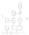
- FIG. 1 shows a first embodiment of a graphical pipeline architecture according to the present invention.
- the graphical pipeline architecture 10 may include, for example, a bus (e.g., a memory bus, a network bus, etc.) 20, a graphical engine 30, a window controller 40, a format converter 50, a color lookup table (CLUT) 60, an aspect ratio converter 70, a cursor CLUT 80, a blender 90 and an anti-flutter filter 100.
- the graphical engine 30 may be coupled to the bus 20 and may be adapted to be in two-way communication with the bus 20.
- the window controller 40 may also be coupled to the bus 20 and may be adapted to be in at least one-way communication with the bus 20.
- the window controller 40 may further be coupled to the format converter 50 and to the cursor CLUT 80.
- the format converter 50 may further be coupled to the CLUT 60 and to the aspect ratio converter 70.
- the aspect ratio converter 70 and the cursor CLUT 80 may additionally be coupled to the blender 90 which, in turn, may be coupled to the anti-flutter filter 100.
- the graphical engine 30 may include, for example, a two-dimensional blitter (e.g., a block transfer engine, a bit block transfer engine, a bit level transaction engine, etc.)
- the blitter may be adapted to perform any of the conventional blitter operations known to one of ordinary skill in the art.
- the blitter may be adapted, for example, to perform scaling, blending and rastering.
- the blitter may scale up or down a particular graphic object or at least a portion of a graphic layer.
- the blitter may also provide an alpha blend or a degree of transparency in the graphics.
- the blitter may also provide a raster operation such as, for example, any logical operations (e.g., AND, XOR, OR, etc.) between two graphical surfaces as is used, for example, in a screen door blend.
- the blitter may not have a direct display capability.
- the graphical engine 30 may include a memory such as, for example, a frame buffer.
- the graphical engine 30 may be adapted to receive multiple video streams via, for example, the bus 20 and to composite them into a single graphics layer stored, for example, in the frame buffer. Since the single graphics layer is a composite, it may be displayed once.
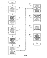
- FIG. 2 shows a flowchart illustrating an embodiment of a process that provides a composite graphics layer using the first embodiment of the graphical pipeline architecture according to the present invention.
- the graphical engine 30 may load, via the bus 20, one or more graphical pipeline streams into its memory. Each of the graphical pipeline streams may provide, for example, a respective graphics layer.
- the graphical engine 30 may composite the loaded graphical pipeline streams into a single graphics layer which, in step 140, may be stored, for example, in the frame buffer of the graphical engine 30.
- the graphical engine 30 may provide, for example, sorting and blending of the graphics layers in forming the composite graphics layer.
- the graphical engine 30 may also provide special functionality such as, for example, video tunneling in portions of the composite graphics layer.
- the loading and compositing of multiple graphical pipeline streams may be background functions and may not be necessarily real-time functions.
- the graphical engine 30 may access multiple graphical pipelines streams stored, for example, in a storage device (e.g., a memory, a hard drive, an optical drive, etc.) or in a network and may composite the multiple graphical pipeline streams into a single composite graphics layer which may be stored in the memory of the graphical engine 30. If sufficient bandwidth is not available for a substantial amount of time, the graphical engine 30 may use a previous composite graphics layer.
- the window controller 40 may access and transport information, via the bus 20, stored in the memory (e.g., the frame buffer) of the graphical engine 30 or elsewhere to the graphical pipeline (e.g., a single graphical pipeline) at the proper time.
- the information may be passed on to the format converter 50.
- the format converter 50 also may receive information from the CLUT 60.
- the CLUT 60 may be, for example, an 8-bit or smaller representation of colors in which each index may represent a different color.
- the format converter 50 may convert the graphics to a particular graphics standard (e.g., 32-bit graphics).
- a particular graphics standard e.g., 32-bit graphics.
- low-bit graphics may be expanded to 32-bit graphics.
- the graphics may be converted to full 32-bit color per pixel graphics.
- the graphics may then be sent to the aspect ratio converter 70.
- the aspect ratio converter 70 may provide scaling (e.g., horizontal scaling) according to a particular scaling standard.
- the aspect ratio converter 70 may scale the graphics for use in a 16x9 European standard display.
- the aspect ratio converter 70 may scale the graphics for use in a 4x3 American standard display.
- the aspect ratio converter 70 may account for square and non-square pixel formats.
- the scaled graphics information may then be sent to the blender 90.
- the window controller 40 may also provide cursor information to the cursor CLUT 80, which may provide cursor color.
- the cursor graphics information may then be sent to the blender 90.
- the blender 90 may provide a weighted blend between the graphics information from the aspect ratio converter 70 and graphics information (e.g., cursor graphics information) from the cursor CLUT 80.
- the cursor graphics may always be placed on top of the graphics information from the aspect ratio converter 70.
- the cursor graphics may be slightly transparent.
- the blended graphics may then be sent to the anti-flutter filter 100.
- the anti-flutter filter 100 may reduce the flutter that may occur between the graphical display and the video display.
- the anti-flutter filter 100 may process the blended graphics information (e.g., smooth the blended graphics).
- the anti-flutter filter 100 may provide a running weighted average using programmable coefficients over several lines of the blended graphics.
- the anti-flutter filter 100 may smooth the edges of a graphical object by providing a weighted average over every 3 or 5 lines of the blended graphics. Thus, each line in the display may be replaced with a weighted average of the surrounding lines, thereby smoothing the graphics, particularly at the edges of graphics, and reducing the flutter.
- the filtered graphical information may be sent to, for example, a video engine in which the filtered graphical information may be blended with the video stream for display with a video output.
- the first embodiment of the present invention may provide one or more of the following advantages.
- the first embodiment may avoid the memory bottlenecks that may occur when the available real-time bandwidth is insufficient.
- the composite graphical layer provided by the graphical engine 30 may not necessarily be displayed in real time. Instead, the graphical layer may be formed from one or more graphical pipeline streams and may be displayed when sufficient bandwidth is available (e.g., during moments when the video and audio are not using too much of the available bandwidth).
- the single graphical pipeline may be physically implemented because the single composite graphical layer may be stored in the graphical engine 30, less bandwidth may be used during the display process than, for example, when multiple real-time graphical pipelines are physically implemented with separate physical pipelines.
- the first embodiment of the present invention may also save valuable chip space without substantially limiting the number of multiple graphical pipeline streams per display pixel. Since increasing the number of graphical pipeline streams may not necessarily increase the number of physical graphical pipelines implemented, there may not be a substantial space constraint as described with respect to the conventional system. Instead of adding a new physical graphical pipeline for each new graphical pipeline stream, the graphical engine 30 may load the additional graphical pipeline stream, for example, during a background operation via the bus 20 and may include the additional graphical pipeline stream in forming a single composite graphical layer which may then be stored in, for example, the frame buffer of the graphical engine 30.
- FIG. 3 shows a second embodiment of a graphical pipeline architecture according to the present invention.
- the graphical pipeline architecture 10 may include, for example, the bus 20, the graphical engine 30, the window controller 40, the format converter 50, the CLUT 60, the cursor CLUT 80 and a compositor 110.
- the graphical engine 30 may be coupled to the bus 20 and may be adapted to be in two-way communication with the bus 20.
- the window controller 40 may also be coupled to the bus 20 and may be in at least one-way communication with the bus 20.
- the window controller 40 may further be coupled to the format converter 50 and to the cursor CLUT 80.
- the format converter 50 may also be coupled to the CLUT 60.
- the format converter 50 and the cursor CLUT 80 may further be coupled to the compositor 110.
- the compositor 110 may include, for example, a blender or a stacker.
- the graphical engine 30 may be adapted to perform many of the operations described above.
- the graphical engine 30 may be adapted to provide aspect ratio conversion and to provide anti-flutter filtering.
- the graphical engine 30 may include, for example, a blitter that may be adapted to filter out or to reduce flutter.
- the blitter may include, for example, a scaling engine that may be adapted, not to change the scale of the graphical information, but to realize a filter function.
- the scaling engine may include an algorithm for scaling that may include a function with weighted coefficients that may be modified such that the scaling does not change and the desired filter function is realized.
- FIG. 4 shows a flowchart illustrating an embodiment of a process that provides a composite graphics layer using the second embodiment of the graphical pipeline architecture according to the present invention.
- the graphical engine 30 may load, via the bus 20, one or more graphical pipeline streams into its memory. Each of the graphical pipeline streams may provide, for example, a respective graphical layer.
- the graphical engine 30 may composite the loaded graphical pipeline streams into a single graphics layer which may be stored, for example, in the memory of the graphical engine 30.
- the graphical engine 30 may provide, for example, sorting and blending of the graphics layers in forming the composite graphics layer.
- the graphical engine 30 may also provide special functionality such as, for example, video tunneling in portions of the composite graphics layer.
- the graphical engine 30 may provide scaling (e.g., horizontal scaling) according to a particular scaling standard.
- the graphical engine 30 may perform the steps that would be performed by the aspect ratio converter 70.
- the graphical engine 30 may employ a scaling engine which may be part of a blitter. The blitter or the scaling engine may then scale a portion of or the entire composite graphics layer for use in a display in accordance with a particular scaling standard (e.g., a 4x3 American standard display, a 16x9 European standard display, etc.)
- the graphical engine 30 may reduce the flutter that may occur between the graphical display and the video display.
- the graphical engine 30 may process the information stored in the composite graphics layer (e.g., smooth graphic objects in the composite graphics layer) to reduce flutter.
- the graphical engine 30 may provide a running weighted average using programmable coefficients over several lines of the composite graphics layer.
- the graphical engine 30 may smooth the edges of a graphical object by providing a weighted average over every 3 or 5 lines of the composite graphics layer.
- each line in the display may be replaced with a weighted average of the surrounding lines, thereby smoothing the graphics, particularly at the edges of graphics, and reducing the flutter.
- the graphical engine 30 may also use a scaling engine which may be part of a blitter.
- the scaling engine may be programmed to generate, for example, a weighted average over a plurality of lines in the composite graphics layer and to replace each line in the composite graphics layer with a corresponding weighted average line.
- the scaling engine may be programmed to provide a 1:1 scaling during the anti-flutter filter algorithm.
- the composite graphics layer which may have been processed to reduce flutter may be stored in the memory (e.g., the frame buffer) of the graphical engine 30.
- Steps 210-250 may be performed in graphical engine 30 as background functions and may not necessarily be real-time functions.
- the graphical engine 30 may access multiple graphical pipelines streams stored, for example, in a storage device (e.g., a memory, a hard drive, an optical drive, etc.) or in a network and may composite the multiple graphical pipeline streams into a single composite graphics layer which may be stored in the memory of the graphical engine 30.
- the information stored in the composite graphics layer may then be scaled for use in, for example, a 4x3 American display and processed to reduce flutter.
- the scaling and processing may be accomplished using a scaling engine of, for example, a blitter.
- the graphical engine 30 may use a previous composite graphics layer for use in the display until sufficient bandwidth is available to update the memory (e.g., the frame buffer) of the graphical engine 30.
- the window controller 40 may access and transport information, via the bus 20, stored in the memory of the graphical engine 30 or elsewhere to the graphical pipeline (e.g., a single graphical pipeline) at the proper time.
- the information may be passed on to the format converter 50.
- the format converter 50 may also receive information from the CLUT 60.
- the format converter 50 may convert the graphics to a particular graphics standard (e.g., 32-bit graphics).
- the converted graphics information may then be sent to the compositor 110.
- the window controller 40 may also provide cursor information to the cursor CLUT 80, which may provide cursor color.
- the cursor graphics information may then be sent to the compositor 110.
- the compositor 110 may provide a weighted blend between the graphics information from the format converter 50 and graphics information (e.g., cursor graphics information) from the cursor CLUT 80.
- graphics information e.g., cursor graphics information
- the cursor graphics may always be placed on top of the graphics information from the aspect ratio converter 70.
- the cursor graphics may be slightly transparent.
- the blended graphical information may be sent to, for example, a video engine in which the blended graphical information may be blended with the video stream for display.
- the second embodiment of the graphical pipeline architecture according to the present invention may include one or more of the advantages described above with respect to the first embodiment of the graphical pipeline architecture according to the present invention.
- the second embodiment may include one or more of the following advantages.
- the hardware may be reduced in the graphical pipeline system with the integration of the aspect ratio converter and the anti-flutter filter with the graphical engine 30.
- the second embodiment may benefit from operational efficiencies by integrating, for example, the anti-flutter filter with the graphical engine 30.
- the anti-flutter filter When the anti-flutter filter is in the graphical pipeline, it might not efficiently access graphical information.
- the anti-flutter filter may load the three lines into its memory or into a line buffer before performing, for example, the weighted averaging and replacing one of the lines with the three-line weighted average.
- the next three lines are processed by the anti-flutter filter, it may have to discard possibly two of the lines in its line buffer in order to perform the three-line weighted average. This process may be bandwidth intensive particularly if the graphical pipeline is operating in real time.
- the second embodiment may provide more efficient use of its memory since it may have the graphical information stored in its frame buffer and, since the graphical engine 30 may not need to operate in real time, bandwidth issues may be minimized. Furthermore, since the graphical information is easily accessible and processed, the graphical engine 30 may be able to better filter the graphical information. For example, programmable multiple-line averaging schemes may easily be implemented or otherwise modified without substantially changing the hardware within the graphical pipeline system.
- FIG. 5 shows an embodiment of a plurality of graphical pipeline architectures sharing a graphical engine according to the present invention.
- the graphical system 300 may include, for example, the bus 20, the graphical engine 30, and a plurality of graphical pipeline systems 310. Although three graphical pipeline systems 310 are illustrated, the present invention may contemplate using more or less than three graphical pipeline systems 310.
- the graphical engine 30 may be coupled to the bus 20 and may be in two-way communication with the bus 20.
- the graphical pipeline systems 310 may each be coupled to the bus 20 and may each be in at least one-way communication with the bus 20.
- Each graphical pipeline system 310 may have an output that may be coupled to a respective independent video output stream.
- the graphical pipeline system 310 may include, for example, at least some of the components described above with respect to the first and the second embodiments of the graphical pipeline architecture 10 (except, for example, the bus 20 and the graphical engine 30). Since the graphical engine 30 may operate as a background engine when a sufficient amount of bandwidth is available, the graphical engine 30 including its memory may be shared by multiple graphical pipeline architectures corresponding to multiple independent video output streams. Time sharing between the graphical pipeline systems 310 may be easily managed where graphical displays are not generated in real time.
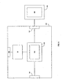
- FIG. 6 shows an example of the graphical pipeline architecture 10 in use in a set top box environment according to the present invention.
- the set top box 320 may include, for example, a graphical interface 330, a transport stream interface 340, a display interface 350, the graphical pipeline architecture 10, a data transport engine 360 which may include, for example, a video engine 370.
- the graphical interface 330 may be coupled to the graphical pipeline architecture 10 which, in turn, may be coupled to the data transport engine 360.
- the graphical pipeline architecture 10 may be coupled to the data transport engine 360 by sharing access to a bus (e.g., the bus 20).
- the transport stream interface 340 may be coupled to the data transport engine 360 which, in turn, may be coupled to the display interface 350.
- a display device 380 which may include a display engine 390, may be coupled to the set top box 320 via the display interface 350.
- a transport stream containing a plurality of channels may enter the set top box 320 via the transport stream interface 340.
- the transport stream may then be passed on to the data transport engine 360 wherein the transport stream may be processed for display in the display device 380 using, for example, the video engine 370.
- the graphical interface 330 may receive graphical information or commands from a user device or from an external storage device (e.g., an external memory, a network, etc.)
- the graphical pipeline architecture 10 may access a storage device (not shown) either in the set top box 320 or, via the graphical interface 330, coupled to the set top box 320.
- the graphical pipeline architecture 10 may provide information about the composite graphics layer (as described above) to the data transport engine 360.
- the video engine 370 may blend the information about the composite graphics layer and the incoming processed transport stream.
- the blended information including the composite graphics layer and the processed transport stream, may be passed to the display device 380 via the display interface 350.
- the display device 380 may then display the blended information via the display engine 390.
Landscapes
- Engineering & Computer Science (AREA)
- Physics & Mathematics (AREA)
- Computer Hardware Design (AREA)
- General Physics & Mathematics (AREA)
- Theoretical Computer Science (AREA)
- Computer Graphics (AREA)
- Controls And Circuits For Display Device (AREA)
- Image Processing (AREA)
- Image Generation (AREA)
Description
- A conventional system provides both real-time video and real-time layered graphics in a layered display. Each layer of the layered graphics is generated by its own separate graphical pipeline. The number of graphical layers that can overlay a position on the screen (e.g., a single video pixel) is therefore limited by the number of separate graphical pipelines that can be implemented in hardware.
- The conventional system may suffer from one or more of the following disadvantages. For example, such a configuration uses a substantial amount of chip space since a graphical pipeline must be added for each desired graphical layer. The addition of more graphical pipelines also increases the cost of producing the chip.
- Furthermore, a plurality of graphical pipelines in concurrent use may exceed the available bandwidth. Each graphical pipeline may have substantial bandwidth requirements, especially where each graphical pipeline is providing a full-screen, real-time graphical surface. However, a plurality of graphical pipelines each concurrently providing a respective full-screen, real-time graphical surface would overload a conventional system. For example, the real-time nature of the graphical demands may create a memory bottleneck, thereby resulting in a failure (e.g., visual and audio display defects due to insufficient memory access when needed). This bandwidth concern also may limit the number of graphical surfaces that may be displayed or the number of graphical pipelines that may be implemented concurrently. Such bandwidth concerns are further exacerbated when multiple video output streams (e.g., independent video output streams) are desired such as, for example, in a multiple video output set top box environment.
- Further limitations and disadvantages of conventional and traditional approaches will become apparent to one of ordinary skill in the art by comparison of such systems with aspects of the present invention as set forth in the remainder of the present application with reference to the drawings.
- US6380945 describes a graphics display system comprising a graphics display pipeline and a video display pipeline. The graphics display pipeline contains a window controller, a format converter and a blender. Between window controller and blender only a single electrical path is adapted.
- A system according to the present invention is set out in claim 1. The present invention may provide a system that provides layered graphics in a video environment. The system may include a bus, a graphical engine and a graphical pipeline. The graphical engine may be coupled to the bus and may be adapted to composite a plurality of graphical layers into a composite graphical layer. The graphical engine may include a memory that stores the composite graphical layer. The graphical pipeline may be coupled to the bus and may be adapted to transport the composite graphical layer.
- These and other features and advantages of the present invention may be appreciated from a review of the following detailed description of the present invention, along with the accompanying figures in which like reference numerals refer to like parts throughout.
-
- FIG. 1 shows a first embodiment of a graphical pipeline architecture according to the present invention.
- FIG. 2 shows a flowchart illustrating an embodiment of a process that provides a composite graphics layer using the first embodiment of the graphical pipeline architecture according to the present invention.
- FIG. 3 shows a second embodiment of the graphical pipeline architecture according to the present invention.
- FIG. 4 shows a flowchart illustrating an embodiment of a process that provides a composite graphics layer using the second embodiment of the graphical pipeline architecture according to the present invention.
- FIG. 5 shows an embodiment of a plurality of graphical pipeline architectures sharing a graphical engine according to the present invention.
- FIG. 6 shows an example of a graphical pipeline architecture in use in a set top box environment according to the present invention.
-
- FIG. 1 shows a first embodiment of a graphical pipeline architecture according to the present invention. The
graphical pipeline architecture 10 may include, for example, a bus (e.g., a memory bus, a network bus, etc.) 20, agraphical engine 30, awindow controller 40, aformat converter 50, a color lookup table (CLUT) 60, an aspect ratio converter 70, a cursor CLUT 80, ablender 90 and ananti-flutter filter 100. Thegraphical engine 30 may be coupled to thebus 20 and may be adapted to be in two-way communication with thebus 20. Thewindow controller 40 may also be coupled to thebus 20 and may be adapted to be in at least one-way communication with thebus 20. Thewindow controller 40 may further be coupled to theformat converter 50 and to the cursor CLUT 80. Theformat converter 50 may further be coupled to theCLUT 60 and to the aspect ratio converter 70. The aspect ratio converter 70 and the cursor CLUT 80 may additionally be coupled to theblender 90 which, in turn, may be coupled to theanti-flutter filter 100. - The
graphical engine 30 may include, for example, a two-dimensional blitter (e.g., a block transfer engine, a bit block transfer engine, a bit level transaction engine, etc.) In one example, the blitter may be adapted to perform any of the conventional blitter operations known to one of ordinary skill in the art. In another example, the blitter may be adapted, for example, to perform scaling, blending and rastering. The blitter may scale up or down a particular graphic object or at least a portion of a graphic layer. The blitter may also provide an alpha blend or a degree of transparency in the graphics. The blitter may also provide a raster operation such as, for example, any logical operations (e.g., AND, XOR, OR, etc.) between two graphical surfaces as is used, for example, in a screen door blend. In one example, the blitter may not have a direct display capability. Thegraphical engine 30 may include a memory such as, for example, a frame buffer. For example, thegraphical engine 30 may be adapted to receive multiple video streams via, for example, thebus 20 and to composite them into a single graphics layer stored, for example, in the frame buffer. Since the single graphics layer is a composite, it may be displayed once. - FIG. 2 shows a flowchart illustrating an embodiment of a process that provides a composite graphics layer using the first embodiment of the graphical pipeline architecture according to the present invention. In
step 120, thegraphical engine 30 may load, via thebus 20, one or more graphical pipeline streams into its memory. Each of the graphical pipeline streams may provide, for example, a respective graphics layer. Instep 130, thegraphical engine 30 may composite the loaded graphical pipeline streams into a single graphics layer which, instep 140, may be stored, for example, in the frame buffer of thegraphical engine 30. Thus, thegraphical engine 30 may provide, for example, sorting and blending of the graphics layers in forming the composite graphics layer. In addition, thegraphical engine 30 may also provide special functionality such as, for example, video tunneling in portions of the composite graphics layer. The loading and compositing of multiple graphical pipeline streams may be background functions and may not be necessarily real-time functions. In one example, when sufficient bandwidth is available (e.g., temporarily available), thegraphical engine 30 may access multiple graphical pipelines streams stored, for example, in a storage device (e.g., a memory, a hard drive, an optical drive, etc.) or in a network and may composite the multiple graphical pipeline streams into a single composite graphics layer which may be stored in the memory of thegraphical engine 30. If sufficient bandwidth is not available for a substantial amount of time, thegraphical engine 30 may use a previous composite graphics layer. - In
step 150, thewindow controller 40 may access and transport information, via thebus 20, stored in the memory (e.g., the frame buffer) of thegraphical engine 30 or elsewhere to the graphical pipeline (e.g., a single graphical pipeline) at the proper time. The information may be passed on to theformat converter 50. Theformat converter 50 also may receive information from theCLUT 60. TheCLUT 60 may be, for example, an 8-bit or smaller representation of colors in which each index may represent a different color. Instep 160, theformat converter 50 may convert the graphics to a particular graphics standard (e.g., 32-bit graphics). Thus, for example, low-bit graphics may be expanded to 32-bit graphics. In another example, the graphics may be converted to full 32-bit color per pixel graphics. The graphics may then be sent to the aspect ratio converter 70. Instep 170, the aspect ratio converter 70 may provide scaling (e.g., horizontal scaling) according to a particular scaling standard. In one example, the aspect ratio converter 70 may scale the graphics for use in a 16x9 European standard display. In another example, the aspect ratio converter 70 may scale the graphics for use in a 4x3 American standard display. In another example, the aspect ratio converter 70 may account for square and non-square pixel formats. The scaled graphics information may then be sent to theblender 90. - Via the
bus 20, for example, thewindow controller 40 may also provide cursor information to the cursor CLUT 80, which may provide cursor color. The cursor graphics information may then be sent to theblender 90. Instep 180, theblender 90 may provide a weighted blend between the graphics information from the aspect ratio converter 70 and graphics information (e.g., cursor graphics information) from the cursor CLUT 80. In one example, the cursor graphics may always be placed on top of the graphics information from the aspect ratio converter 70. In another example, the cursor graphics may be slightly transparent. The blended graphics may then be sent to theanti-flutter filter 100. - In
step 190, theanti-flutter filter 100 may reduce the flutter that may occur between the graphical display and the video display. For example, theanti-flutter filter 100 may process the blended graphics information (e.g., smooth the blended graphics). In one example, theanti-flutter filter 100 may provide a running weighted average using programmable coefficients over several lines of the blended graphics. For example, theanti-flutter filter 100 may smooth the edges of a graphical object by providing a weighted average over every 3 or 5 lines of the blended graphics. Thus, each line in the display may be replaced with a weighted average of the surrounding lines, thereby smoothing the graphics, particularly at the edges of graphics, and reducing the flutter. Instep 200, the filtered graphical information may be sent to, for example, a video engine in which the filtered graphical information may be blended with the video stream for display with a video output. - The first embodiment of the present invention may provide one or more of the following advantages. For example, the first embodiment may avoid the memory bottlenecks that may occur when the available real-time bandwidth is insufficient. In one example, although the video and audio may be displayed in real time, the composite graphical layer provided by the
graphical engine 30 may not necessarily be displayed in real time. Instead, the graphical layer may be formed from one or more graphical pipeline streams and may be displayed when sufficient bandwidth is available (e.g., during moments when the video and audio are not using too much of the available bandwidth). In addition, since a single graphical pipeline may be physically implemented because the single composite graphical layer may be stored in thegraphical engine 30, less bandwidth may be used during the display process than, for example, when multiple real-time graphical pipelines are physically implemented with separate physical pipelines. - The first embodiment of the present invention may also save valuable chip space without substantially limiting the number of multiple graphical pipeline streams per display pixel. Since increasing the number of graphical pipeline streams may not necessarily increase the number of physical graphical pipelines implemented, there may not be a substantial space constraint as described with respect to the conventional system. Instead of adding a new physical graphical pipeline for each new graphical pipeline stream, the
graphical engine 30 may load the additional graphical pipeline stream, for example, during a background operation via thebus 20 and may include the additional graphical pipeline stream in forming a single composite graphical layer which may then be stored in, for example, the frame buffer of thegraphical engine 30. - FIG. 3 shows a second embodiment of a graphical pipeline architecture according to the present invention. The
graphical pipeline architecture 10 may include, for example, thebus 20, thegraphical engine 30, thewindow controller 40, theformat converter 50, theCLUT 60, the cursor CLUT 80 and acompositor 110. Thegraphical engine 30 may be coupled to thebus 20 and may be adapted to be in two-way communication with thebus 20. Thewindow controller 40 may also be coupled to thebus 20 and may be in at least one-way communication with thebus 20. Thewindow controller 40 may further be coupled to theformat converter 50 and to the cursor CLUT 80. Theformat converter 50 may also be coupled to theCLUT 60. Theformat converter 50 and the cursor CLUT 80 may further be coupled to thecompositor 110. Thecompositor 110 may include, for example, a blender or a stacker. - The
graphical engine 30 may be adapted to perform many of the operations described above. In addition, thegraphical engine 30 may be adapted to provide aspect ratio conversion and to provide anti-flutter filtering. In one example, thegraphical engine 30 may include, for example, a blitter that may be adapted to filter out or to reduce flutter. The blitter may include, for example, a scaling engine that may be adapted, not to change the scale of the graphical information, but to realize a filter function. The scaling engine may include an algorithm for scaling that may include a function with weighted coefficients that may be modified such that the scaling does not change and the desired filter function is realized. - FIG. 4 shows a flowchart illustrating an embodiment of a process that provides a composite graphics layer using the second embodiment of the graphical pipeline architecture according to the present invention. In
step 210, thegraphical engine 30 may load, via thebus 20, one or more graphical pipeline streams into its memory. Each of the graphical pipeline streams may provide, for example, a respective graphical layer. Instep 220, thegraphical engine 30 may composite the loaded graphical pipeline streams into a single graphics layer which may be stored, for example, in the memory of thegraphical engine 30. Thus, thegraphical engine 30 may provide, for example, sorting and blending of the graphics layers in forming the composite graphics layer. In addition, thegraphical engine 30 may also provide special functionality such as, for example, video tunneling in portions of the composite graphics layer. - In
step 230, thegraphical engine 30 may provide scaling (e.g., horizontal scaling) according to a particular scaling standard. In one example, thegraphical engine 30 may perform the steps that would be performed by the aspect ratio converter 70. Thegraphical engine 30 may employ a scaling engine which may be part of a blitter. The blitter or the scaling engine may then scale a portion of or the entire composite graphics layer for use in a display in accordance with a particular scaling standard (e.g., a 4x3 American standard display, a 16x9 European standard display, etc.) - In
step 240, thegraphical engine 30 may reduce the flutter that may occur between the graphical display and the video display. For example, thegraphical engine 30 may process the information stored in the composite graphics layer (e.g., smooth graphic objects in the composite graphics layer) to reduce flutter. In one example, thegraphical engine 30 may provide a running weighted average using programmable coefficients over several lines of the composite graphics layer. For example, thegraphical engine 30 may smooth the edges of a graphical object by providing a weighted average over every 3 or 5 lines of the composite graphics layer. Thus, each line in the display may be replaced with a weighted average of the surrounding lines, thereby smoothing the graphics, particularly at the edges of graphics, and reducing the flutter. Thegraphical engine 30 may also use a scaling engine which may be part of a blitter. By changing the programmable coefficients used by the scaling engine during a scaling algorithm, the scaling engine may be programmed to generate, for example, a weighted average over a plurality of lines in the composite graphics layer and to replace each line in the composite graphics layer with a corresponding weighted average line. Furthermore, the scaling engine may be programmed to provide a 1:1 scaling during the anti-flutter filter algorithm. Instep 250, the composite graphics layer which may have been processed to reduce flutter may be stored in the memory (e.g., the frame buffer) of thegraphical engine 30. - Steps 210-250, for example, may be performed in
graphical engine 30 as background functions and may not necessarily be real-time functions. In one example, when sufficient bandwidth is available (e.g., temporarily available), thegraphical engine 30 may access multiple graphical pipelines streams stored, for example, in a storage device (e.g., a memory, a hard drive, an optical drive, etc.) or in a network and may composite the multiple graphical pipeline streams into a single composite graphics layer which may be stored in the memory of thegraphical engine 30. The information stored in the composite graphics layer may then be scaled for use in, for example, a 4x3 American display and processed to reduce flutter. The scaling and processing may be accomplished using a scaling engine of, for example, a blitter. If sufficient bandwidth is not available to thegraphical engine 30 for a substantial amount of time, thegraphical engine 30 may use a previous composite graphics layer for use in the display until sufficient bandwidth is available to update the memory (e.g., the frame buffer) of thegraphical engine 30. - In
step 260, thewindow controller 40 may access and transport information, via thebus 20, stored in the memory of thegraphical engine 30 or elsewhere to the graphical pipeline (e.g., a single graphical pipeline) at the proper time. The information may be passed on to theformat converter 50. Theformat converter 50 may also receive information from theCLUT 60. Instep 270, theformat converter 50 may convert the graphics to a particular graphics standard (e.g., 32-bit graphics). The converted graphics information may then be sent to thecompositor 110. Via thebus 20, for example, thewindow controller 40 may also provide cursor information to the cursor CLUT 80, which may provide cursor color. The cursor graphics information may then be sent to thecompositor 110. Instep 280, thecompositor 110 may provide a weighted blend between the graphics information from theformat converter 50 and graphics information (e.g., cursor graphics information) from the cursor CLUT 80. In one example, the cursor graphics may always be placed on top of the graphics information from the aspect ratio converter 70. In another example, the cursor graphics may be slightly transparent. Instep 290, the blended graphical information may be sent to, for example, a video engine in which the blended graphical information may be blended with the video stream for display. - The second embodiment of the graphical pipeline architecture according to the present invention may include one or more of the advantages described above with respect to the first embodiment of the graphical pipeline architecture according to the present invention. In addition, the second embodiment may include one or more of the following advantages. For example, the hardware may be reduced in the graphical pipeline system with the integration of the aspect ratio converter and the anti-flutter filter with the
graphical engine 30. - In addition, the second embodiment may benefit from operational efficiencies by integrating, for example, the anti-flutter filter with the
graphical engine 30. When the anti-flutter filter is in the graphical pipeline, it might not efficiently access graphical information. For example, in order to perform averaging over three lines, the anti-flutter filter may load the three lines into its memory or into a line buffer before performing, for example, the weighted averaging and replacing one of the lines with the three-line weighted average. When the next three lines are processed by the anti-flutter filter, it may have to discard possibly two of the lines in its line buffer in order to perform the three-line weighted average. This process may be bandwidth intensive particularly if the graphical pipeline is operating in real time. The second embodiment may provide more efficient use of its memory since it may have the graphical information stored in its frame buffer and, since thegraphical engine 30 may not need to operate in real time, bandwidth issues may be minimized. Furthermore, since the graphical information is easily accessible and processed, thegraphical engine 30 may be able to better filter the graphical information. For example, programmable multiple-line averaging schemes may easily be implemented or otherwise modified without substantially changing the hardware within the graphical pipeline system. - FIG. 5 shows an embodiment of a plurality of graphical pipeline architectures sharing a graphical engine according to the present invention. The
graphical system 300 may include, for example, thebus 20, thegraphical engine 30, and a plurality ofgraphical pipeline systems 310. Although threegraphical pipeline systems 310 are illustrated, the present invention may contemplate using more or less than threegraphical pipeline systems 310. Thegraphical engine 30 may be coupled to thebus 20 and may be in two-way communication with thebus 20. Thegraphical pipeline systems 310 may each be coupled to thebus 20 and may each be in at least one-way communication with thebus 20. Eachgraphical pipeline system 310 may have an output that may be coupled to a respective independent video output stream. Thegraphical pipeline system 310 may include, for example, at least some of the components described above with respect to the first and the second embodiments of the graphical pipeline architecture 10 (except, for example, thebus 20 and the graphical engine 30). Since thegraphical engine 30 may operate as a background engine when a sufficient amount of bandwidth is available, thegraphical engine 30 including its memory may be shared by multiple graphical pipeline architectures corresponding to multiple independent video output streams. Time sharing between thegraphical pipeline systems 310 may be easily managed where graphical displays are not generated in real time. - Although embodiments of the present invention may find many applications in a myriad of fields, FIG. 6 shows an example of the
graphical pipeline architecture 10 in use in a set top box environment according to the present invention. The settop box 320 may include, for example, agraphical interface 330, atransport stream interface 340, adisplay interface 350, thegraphical pipeline architecture 10, adata transport engine 360 which may include, for example, avideo engine 370. Thegraphical interface 330 may be coupled to thegraphical pipeline architecture 10 which, in turn, may be coupled to thedata transport engine 360. In one example, thegraphical pipeline architecture 10 may be coupled to thedata transport engine 360 by sharing access to a bus (e.g., the bus 20). Thetransport stream interface 340 may be coupled to thedata transport engine 360 which, in turn, may be coupled to thedisplay interface 350. Adisplay device 380, which may include adisplay engine 390, may be coupled to the settop box 320 via thedisplay interface 350. - In operation, a transport stream containing a plurality of channels may enter the set
top box 320 via thetransport stream interface 340. The transport stream may then be passed on to thedata transport engine 360 wherein the transport stream may be processed for display in thedisplay device 380 using, for example, thevideo engine 370. Thegraphical interface 330 may receive graphical information or commands from a user device or from an external storage device (e.g., an external memory, a network, etc.) Thegraphical pipeline architecture 10 may access a storage device (not shown) either in the settop box 320 or, via thegraphical interface 330, coupled to the settop box 320. Thegraphical pipeline architecture 10 may provide information about the composite graphics layer (as described above) to thedata transport engine 360. In one example, thevideo engine 370 may blend the information about the composite graphics layer and the incoming processed transport stream. The blended information, including the composite graphics layer and the processed transport stream, may be passed to thedisplay device 380 via thedisplay interface 350. Thedisplay device 380 may then display the blended information via thedisplay engine 390. - While the present invention has been described with reference to certain embodiments, it will be understood by those skilled in the art that various changes may be made and equivalents may be substituted without departing from the scope of the present invention. In addition, many modifications may be made to adapt a particular situation or material to the teachings of the present invention without departing from its scope. Therefore, it is intended that the present invention not be limited to the particular embodiment disclosed, but that the present invention will include all embodiments falling within the scope of the appended claims.
Claims (12)
- A system for providing layered graphics in a video environment, comprising:characterized bya bus (20);a graphical engine (30) coupled to the bus, the graphical engine (30) being adapted to composite a plurality of graphical layers into a composite graphical layer and comprising a memory that stores the composite graphical layer;a graphical pipeline coupled to the bus (20), the graphical pipeline being adapted to transport the composite graphical layer;
said graphical pipeline comprising a window controller (40) coupled to said bus (20) and a blender (90, 110),
said window controller (40) is coupled to said blender (90, 110) via a first electrical path comprising a format converter (50) and
a second electrical path comprising a cursor color look-up table (80), whereat said first electrical path and said second electrical path are arranged parallel between said window controller (40) and said blender (90, 110). - The system of claim 1, wherein said format converter (50) is coupled to a color look-up table CLUT (60).
- The system of claim 1, wherein said first path comprising an aspect ratio converter (70) connected with said format converter (50) and said blender (90).
- The system of claim 1, wherein said blender (90) is coupled to a anti-flutter filter (100).
- The system of claim 1, comprising a compositor (110) connected with said first path and said second path, whereat said compositor (110) comprising a blender.
- The system of claim 5 comprising an anti-flutter filter (100) coupled to said compositor (110).
- The system of claim 1, wherein the graphical engine (30) is not a real-time client.
- The system of claim 1, wherein the graphical engine (30) comprises a hardware graphical engine.
- The system of claim 1, wherein the graphical engine (30) comprises a blitter.
- The system of claim 1, wherein the graphical engine (30) is adapted to reduce flutter in a graphical display.
- The system of claim 1, wherein the graphical engine (30) is adapted to convert graphical information to a particular aspect ratio.
- The system of claim 1, wherein the graphical engine (30) is adapted to provide video tunneling.
Applications Claiming Priority (2)
| Application Number | Priority Date | Filing Date | Title |
|---|---|---|---|
| US10/201,017 US6982727B2 (en) | 2002-07-23 | 2002-07-23 | System and method for providing graphics using graphical engine |
| US201017 | 2002-07-23 |
Publications (2)
| Publication Number | Publication Date |
|---|---|
| EP1385339A1 EP1385339A1 (en) | 2004-01-28 |
| EP1385339B1 true EP1385339B1 (en) | 2005-11-16 |
Family
ID=30000079
Family Applications (1)
| Application Number | Title | Priority Date | Filing Date |
|---|---|---|---|
| EP03016705A Expired - Lifetime EP1385339B1 (en) | 2002-07-23 | 2003-07-22 | System for providing graphics using graphical engine |
Country Status (3)
| Country | Link |
|---|---|
| US (5) | US6982727B2 (en) |
| EP (1) | EP1385339B1 (en) |
| DE (1) | DE60302292T2 (en) |
Families Citing this family (14)
| Publication number | Priority date | Publication date | Assignee | Title |
|---|---|---|---|---|
| US6982727B2 (en) | 2002-07-23 | 2006-01-03 | Broadcom Corporation | System and method for providing graphics using graphical engine |
| JP4300767B2 (en) | 2002-08-05 | 2009-07-22 | ソニー株式会社 | Guide system, content server, portable device, information processing method, information processing program, and storage medium |
| EP1603335B1 (en) * | 2003-02-19 | 2008-04-30 | Matsushita Electric Industrial Co., Ltd. | Recording medium, reproduction device, recording method, program, and reproduction method |
| US8063916B2 (en) * | 2003-10-22 | 2011-11-22 | Broadcom Corporation | Graphics layer reduction for video composition |
| US8543420B2 (en) * | 2007-09-19 | 2013-09-24 | Fresenius Medical Care Holdings, Inc. | Patient-specific content delivery methods and systems |
| US20080207007A1 (en) | 2007-02-27 | 2008-08-28 | Air Products And Chemicals, Inc. | Plasma Enhanced Cyclic Chemical Vapor Deposition of Silicon-Containing Films |
| US8340507B2 (en) * | 2007-05-31 | 2012-12-25 | Panasonic Corporation | Recording medium, playback apparatus, recording method, program, and playback method |
| US9024966B2 (en) * | 2007-09-07 | 2015-05-05 | Qualcomm Incorporated | Video blending using time-averaged color keys |
| US20100164839A1 (en) * | 2008-12-31 | 2010-07-01 | Lyons Kenton M | Peer-to-peer dynamically appendable logical displays |
| US8698741B1 (en) | 2009-01-16 | 2014-04-15 | Fresenius Medical Care Holdings, Inc. | Methods and apparatus for medical device cursor control and touchpad-based navigation |
| US8632485B2 (en) * | 2009-11-05 | 2014-01-21 | Fresenius Medical Care Holdings, Inc. | Patient treatment and monitoring systems and methods |
| US10799117B2 (en) | 2009-11-05 | 2020-10-13 | Fresenius Medical Care Holdings, Inc. | Patient treatment and monitoring systems and methods with cause inferencing |
| EP2988269B1 (en) * | 2014-08-21 | 2018-06-13 | Advanced Digital Broadcast S.A. | A system and method for scaling and copying graphics |
| CN116469138B (en) * | 2021-06-15 | 2024-03-29 | 荣耀终端有限公司 | Light spot display method and device |
Family Cites Families (81)
| Publication number | Priority date | Publication date | Assignee | Title |
|---|---|---|---|---|
| DE3176454D1 (en) * | 1980-02-22 | 1987-10-22 | Toshiba Kk | Liquid crystal display device |
| US4630355A (en) * | 1985-03-08 | 1986-12-23 | Energy Conversion Devices, Inc. | Electric circuits having repairable circuit lines and method of making the same |
| US4773738A (en) * | 1986-08-27 | 1988-09-27 | Canon Kabushiki Kaisha | Optical modulation device using ferroelectric liquid crystal and AC and DC driving voltages |
| JP2852042B2 (en) * | 1987-10-05 | 1999-01-27 | 株式会社日立製作所 | Display device |
| US5125045A (en) * | 1987-11-20 | 1992-06-23 | Hitachi, Ltd. | Image processing system |
| US4996523A (en) * | 1988-10-20 | 1991-02-26 | Eastman Kodak Company | Electroluminescent storage display with improved intensity driver circuits |
| US5339090A (en) * | 1989-06-23 | 1994-08-16 | Northern Telecom Limited | Spatial light modulators |
| US6020894A (en) * | 1990-08-16 | 2000-02-01 | Canon Kabushiki Kaisha | Full-color desktop publishing system |
| JP3143497B2 (en) * | 1990-08-22 | 2001-03-07 | キヤノン株式会社 | Liquid crystal device |
| US6097357A (en) * | 1990-11-28 | 2000-08-01 | Fujitsu Limited | Full color surface discharge type plasma display device |
| US5225823A (en) * | 1990-12-04 | 1993-07-06 | Harris Corporation | Field sequential liquid crystal display with memory integrated within the liquid crystal panel |
| US5424752A (en) * | 1990-12-10 | 1995-06-13 | Semiconductor Energy Laboratory Co., Ltd. | Method of driving an electro-optical device |
| US5629720A (en) * | 1991-02-05 | 1997-05-13 | Hewlett-Packard Company | Display mode processor |
| EP0499979A3 (en) * | 1991-02-16 | 1993-06-09 | Semiconductor Energy Laboratory Co., Ltd. | Electro-optical device |
| US5608549A (en) * | 1991-06-11 | 1997-03-04 | Canon Kabushiki Kaisha | Apparatus and method for processing a color image |
| JPH0667620A (en) * | 1991-07-27 | 1994-03-11 | Semiconductor Energy Lab Co Ltd | Image display device |
| US5311204A (en) * | 1991-08-28 | 1994-05-10 | Tektronix, Inc. | Offset electrodes |
| JP2775040B2 (en) * | 1991-10-29 | 1998-07-09 | 株式会社 半導体エネルギー研究所 | Electro-optical display device and driving method thereof |
| US5471225A (en) * | 1993-04-28 | 1995-11-28 | Dell Usa, L.P. | Liquid crystal display with integrated frame buffer |
| US5274190A (en) * | 1993-05-24 | 1993-12-28 | E. I. Du Pont De Nemours And Company | Process for the manufacture of linear hydrofluorocarbons containing end group hydrogen substituents |
| US5416043A (en) * | 1993-07-12 | 1995-05-16 | Peregrine Semiconductor Corporation | Minimum charge FET fabricated on an ultrathin silicon on sapphire wafer |
| US5798746A (en) * | 1993-12-27 | 1998-08-25 | Semiconductor Energy Laboratory Co., Ltd. | Liquid crystal display device |
| JP3626514B2 (en) * | 1994-01-21 | 2005-03-09 | 株式会社ルネサステクノロジ | Image processing circuit |
| US5642129A (en) * | 1994-03-23 | 1997-06-24 | Kopin Corporation | Color sequential display panels |
| JP3672586B2 (en) * | 1994-03-24 | 2005-07-20 | 株式会社半導体エネルギー研究所 | Correction system and operation method thereof |
| JPH08101669A (en) * | 1994-09-30 | 1996-04-16 | Semiconductor Energy Lab Co Ltd | Display device drive circuit |
| US5771031A (en) * | 1994-10-26 | 1998-06-23 | Kabushiki Kaisha Toshiba | Flat-panel display device and driving method of the same |
| JP3630489B2 (en) * | 1995-02-16 | 2005-03-16 | 株式会社東芝 | Liquid crystal display |
| US5959598A (en) * | 1995-07-20 | 1999-09-28 | The Regents Of The University Of Colorado | Pixel buffer circuits for implementing improved methods of displaying grey-scale or color images |
| US6016150A (en) * | 1995-08-04 | 2000-01-18 | Microsoft Corporation | Sprite compositor and method for performing lighting and shading operations using a compositor to combine factored image layers |
| JP3526992B2 (en) * | 1995-11-06 | 2004-05-17 | 株式会社半導体エネルギー研究所 | Matrix type display device |
| US5945972A (en) * | 1995-11-30 | 1999-08-31 | Kabushiki Kaisha Toshiba | Display device |
| WO1997032297A1 (en) * | 1996-02-27 | 1997-09-04 | The Penn State Research Foundation | Method and system for the reduction of off-state current in field-effect transistors |
| JPH10104663A (en) * | 1996-09-27 | 1998-04-24 | Semiconductor Energy Lab Co Ltd | Electrooptic device and its formation |
| US6311204B1 (en) * | 1996-10-11 | 2001-10-30 | C-Cube Semiconductor Ii Inc. | Processing system with register-based process sharing |
| US6545654B2 (en) * | 1996-10-31 | 2003-04-08 | Kopin Corporation | Microdisplay for portable communication systems |
| US5990629A (en) * | 1997-01-28 | 1999-11-23 | Casio Computer Co., Ltd. | Electroluminescent display device and a driving method thereof |
| TW379360B (en) * | 1997-03-03 | 2000-01-11 | Semiconductor Energy Lab | Method of manufacturing a semiconductor device |
| US6380917B2 (en) * | 1997-04-18 | 2002-04-30 | Seiko Epson Corporation | Driving circuit of electro-optical device, driving method for electro-optical device, and electro-optical device and electronic equipment employing the electro-optical device |
| JPH1173158A (en) * | 1997-08-28 | 1999-03-16 | Seiko Epson Corp | Display element |
| JP3533074B2 (en) * | 1997-10-20 | 2004-05-31 | 日本電気株式会社 | LED panel with built-in VRAM function |
| JP3279238B2 (en) * | 1997-12-01 | 2002-04-30 | 株式会社日立製作所 | Liquid crystal display |
| US6115019A (en) * | 1998-02-25 | 2000-09-05 | Agilent Technologies | Register pixel for liquid crystal displays |
| JPH11282006A (en) * | 1998-03-27 | 1999-10-15 | Sony Corp | Liquid crystal display |
| US6246386B1 (en) * | 1998-06-18 | 2001-06-12 | Agilent Technologies, Inc. | Integrated micro-display system |
| FR2780803B1 (en) * | 1998-07-03 | 2002-10-31 | Thomson Csf | CONTROL OF A LOW ELECTRONIC AFFINITY CATHODES SCREEN |
| JP3865942B2 (en) * | 1998-07-17 | 2007-01-10 | 富士フイルムホールディングス株式会社 | Active matrix element, light emitting element using the active matrix element, light modulation element, light detection element, exposure element, display device |
| DE69934201T2 (en) * | 1998-08-04 | 2007-09-20 | Seiko Epson Corp. | ELECTROOPTICAL UNIT AND ELECTRONIC UNIT |
| KR100533802B1 (en) * | 1998-09-10 | 2005-12-06 | 세이코 엡슨 가부시키가이샤 | Substrate for liquid crystal panel, liquid crystal panel, electronic apparatus comprising the panel, and method for manufacturing substrate for liquid crystal panel |
| US6591347B2 (en) | 1998-10-09 | 2003-07-08 | National Semiconductor Corporation | Dynamic replacement technique in a shared cache |
| US6274887B1 (en) * | 1998-11-02 | 2001-08-14 | Semiconductor Energy Laboratory Co., Ltd. | Semiconductor device and manufacturing method therefor |
| WO2000028518A2 (en) | 1998-11-09 | 2000-05-18 | Broadcom Corporation | Graphics display system |
| JP3403097B2 (en) * | 1998-11-24 | 2003-05-06 | 株式会社東芝 | D / A conversion circuit and liquid crystal display device |
| US6157415A (en) * | 1998-12-15 | 2000-12-05 | Ati International Srl | Method and apparatus for dynamically blending image input layers |
| US6266178B1 (en) * | 1998-12-28 | 2001-07-24 | Texas Instruments Incorporated | Guardring DRAM cell |
| US6621499B1 (en) * | 1999-01-04 | 2003-09-16 | Ati International Srl | Video processor with multiple overlay generators and/or flexible bidirectional video data port |
| US6738054B1 (en) * | 1999-02-08 | 2004-05-18 | Fuji Photo Film Co., Ltd. | Method and apparatus for image display |
| US6670938B1 (en) * | 1999-02-16 | 2003-12-30 | Canon Kabushiki Kaisha | Electronic circuit and liquid crystal display apparatus including same |
| US6259846B1 (en) * | 1999-02-23 | 2001-07-10 | Sarnoff Corporation | Light-emitting fiber, as for a display |
| JP2000259124A (en) * | 1999-03-05 | 2000-09-22 | Sanyo Electric Co Ltd | Electroluminescence display device |
| US6344743B1 (en) * | 1999-03-05 | 2002-02-05 | The United States Of America As Represented By The Secretary Of The Navy | Standing wave magnetometer |
| JP2000276108A (en) * | 1999-03-24 | 2000-10-06 | Sanyo Electric Co Ltd | Active el display device |
| KR100563826B1 (en) * | 1999-08-21 | 2006-04-17 | 엘지.필립스 엘시디 주식회사 | Data driving circuit of liquid crystal display |
| US6441829B1 (en) * | 1999-09-30 | 2002-08-27 | Agilent Technologies, Inc. | Pixel driver that generates, in response to a digital input value, a pixel drive signal having a duty cycle that determines the apparent brightness of the pixel |
| DE60009140T2 (en) | 1999-12-14 | 2005-02-03 | Broadcom Corp., Irvine | METHOD AND SYSTEM FOR DECODING VIDEOS SEQUENCES AND GRAPHICS |
| TW573165B (en) * | 1999-12-24 | 2004-01-21 | Sanyo Electric Co | Display device |
| US7483042B1 (en) * | 2000-01-13 | 2009-01-27 | Ati International, Srl | Video graphics module capable of blending multiple image layers |
| JP3835113B2 (en) * | 2000-04-26 | 2006-10-18 | セイコーエプソン株式会社 | Data line driving circuit of electro-optical panel, control method thereof, electro-optical device, and electronic apparatus |
| TW522374B (en) * | 2000-08-08 | 2003-03-01 | Semiconductor Energy Lab | Electro-optical device and driving method of the same |
| US6992652B2 (en) * | 2000-08-08 | 2006-01-31 | Semiconductor Energy Laboratory Co., Ltd. | Liquid crystal display device and driving method thereof |
| US6987496B2 (en) * | 2000-08-18 | 2006-01-17 | Semiconductor Energy Laboratory Co., Ltd. | Electronic device and method of driving the same |
| TW518552B (en) * | 2000-08-18 | 2003-01-21 | Semiconductor Energy Lab | Liquid crystal display device, method of driving the same, and method of driving a portable information device having the liquid crystal display device |
| US7180496B2 (en) * | 2000-08-18 | 2007-02-20 | Semiconductor Energy Laboratory Co., Ltd. | Liquid crystal display device and method of driving the same |
| TW514854B (en) * | 2000-08-23 | 2002-12-21 | Semiconductor Energy Lab | Portable information apparatus and method of driving the same |
| KR100823047B1 (en) * | 2000-10-02 | 2008-04-18 | 가부시키가이샤 한도오따이 에네루기 켄큐쇼 | Self-luminescent device and driving method thereof |
| US7184014B2 (en) * | 2000-10-05 | 2007-02-27 | Semiconductor Energy Laboratory Co., Ltd. | Liquid crystal display device |
| US6430073B1 (en) * | 2000-12-06 | 2002-08-06 | International Business Machines Corporation | Dram CAM cell with hidden refresh |
| US6747623B2 (en) * | 2001-02-09 | 2004-06-08 | Semiconductor Energy Laboratory Co., Ltd. | Liquid crystal display device and method of driving the same |
| TWI273539B (en) * | 2001-11-29 | 2007-02-11 | Semiconductor Energy Lab | Display device and display system using the same |
| US6982727B2 (en) | 2002-07-23 | 2006-01-03 | Broadcom Corporation | System and method for providing graphics using graphical engine |
| JP4099578B2 (en) * | 2002-12-09 | 2008-06-11 | ソニー株式会社 | Semiconductor device and image data processing apparatus |
-
2002
- 2002-07-23 US US10/201,017 patent/US6982727B2/en not_active Expired - Lifetime
-
2003
- 2003-07-22 DE DE60302292T patent/DE60302292T2/en not_active Expired - Lifetime
- 2003-07-22 EP EP03016705A patent/EP1385339B1/en not_active Expired - Lifetime
-
2005
- 2005-04-29 US US11/118,275 patent/US7304652B2/en not_active Expired - Lifetime
-
2007
- 2007-11-07 US US11/936,426 patent/US7567261B2/en not_active Expired - Lifetime
-
2009
- 2009-06-24 US US12/490,570 patent/US8345065B2/en not_active Expired - Fee Related
-
2012
- 2012-12-31 US US13/731,201 patent/US8698842B2/en not_active Expired - Fee Related
Also Published As
| Publication number | Publication date |
|---|---|
| EP1385339A1 (en) | 2004-01-28 |
| US7304652B2 (en) | 2007-12-04 |
| US8698842B2 (en) | 2014-04-15 |
| US6982727B2 (en) | 2006-01-03 |
| US20080062200A1 (en) | 2008-03-13 |
| US20040017383A1 (en) | 2004-01-29 |
| US7567261B2 (en) | 2009-07-28 |
| DE60302292T2 (en) | 2006-07-20 |
| US20130120448A1 (en) | 2013-05-16 |
| US8345065B2 (en) | 2013-01-01 |
| US20050190201A1 (en) | 2005-09-01 |
| US20090262240A1 (en) | 2009-10-22 |
| DE60302292D1 (en) | 2005-12-22 |
Similar Documents
| Publication | Publication Date | Title |
|---|---|---|
| US8698842B2 (en) | System and method for providing graphics using graphical engine | |
| US7602406B2 (en) | Compositing images from multiple sources | |
| US6023302A (en) | Blending of video images in a home communications terminal | |
| JP5123282B2 (en) | Method and apparatus for facilitating processing of interlaced video images for progressive video display | |
| US7420569B2 (en) | Adaptive pixel-based blending method and system | |
| JP4309270B2 (en) | System and method for generating visual representations of graphic data and digital document processing | |
| US7365757B1 (en) | Method and apparatus for independent video and graphics scaling in a video graphics system | |
| US20110080519A1 (en) | System and method for efficiently processing digital video | |
| EP0457297B1 (en) | Display apparatus | |
| US7710434B2 (en) | Rotation and scaling optimization for mobile devices | |
| US20150138237A1 (en) | Systems and methods for compositing a display image from display planes using enhanced blending hardware | |
| EP1043891A2 (en) | Method and apparatus for clipping video information before scaling | |
| WO2015020773A1 (en) | Video data compression format | |
| US20170302899A1 (en) | Facilitating interaction between video renderers and graphics device drivers | |
| US20080238939A1 (en) | Video compositing device and video output device | |
| US6317134B1 (en) | System software for use in a graphics computer system having a shared system memory and supporting DM Pbuffers and other constructs aliased as DM buffers | |
| US6070002A (en) | System software for use in a graphics computer system having a shared system memory | |
| US20180288353A1 (en) | Low power video composition using a stream out buffer | |
| CN111045623A (en) | Method for processing graphics commands in multi-GPU (graphics processing Unit) splicing environment | |
| JP5394447B2 (en) | Strategies for processing image information using color information data structures | |
| HK1060239B (en) | Facilitating interaction between video renderers and graphics device drivers |
Legal Events
| Date | Code | Title | Description |
|---|---|---|---|
| PUAI | Public reference made under article 153(3) epc to a published international application that has entered the european phase |
Free format text: ORIGINAL CODE: 0009012 |
|
| AK | Designated contracting states |
Kind code of ref document: A1 Designated state(s): AT BE BG CH CY CZ DE DK EE ES FI FR GB GR HU IE IT LI LU MC NL PT RO SE SI SK TR |
|
| AX | Request for extension of the european patent |
Extension state: AL LT LV MK |
|
| 17P | Request for examination filed |
Effective date: 20040728 |
|
| 17Q | First examination report despatched |
Effective date: 20040820 |
|
| AKX | Designation fees paid |
Designated state(s): DE FR GB |
|
| GRAP | Despatch of communication of intention to grant a patent |
Free format text: ORIGINAL CODE: EPIDOSNIGR1 |
|
| RTI1 | Title (correction) |
Free format text: SYSTEM FOR PROVIDING GRAPHICS USING GRAPHICAL ENGINE |
|
| GRAS | Grant fee paid |
Free format text: ORIGINAL CODE: EPIDOSNIGR3 |
|
| GRAA | (expected) grant |
Free format text: ORIGINAL CODE: 0009210 |
|
| AK | Designated contracting states |
Kind code of ref document: B1 Designated state(s): DE FR GB |
|
| REG | Reference to a national code |
Ref country code: GB Ref legal event code: FG4D |
|
| REF | Corresponds to: |
Ref document number: 60302292 Country of ref document: DE Date of ref document: 20051222 Kind code of ref document: P |
|
| ET | Fr: translation filed | ||
| PLBI | Opposition filed |
Free format text: ORIGINAL CODE: 0009260 |
|
| PLAX | Notice of opposition and request to file observation + time limit sent |
Free format text: ORIGINAL CODE: EPIDOSNOBS2 |
|
| 26 | Opposition filed |
Opponent name: QUALCOMM INCORPORATED Effective date: 20060816 |
|
| PLAF | Information modified related to communication of a notice of opposition and request to file observations + time limit |
Free format text: ORIGINAL CODE: EPIDOSCOBS2 |
|
| PLBB | Reply of patent proprietor to notice(s) of opposition received |
Free format text: ORIGINAL CODE: EPIDOSNOBS3 |
|
| RAP2 | Party data changed (patent owner data changed or rights of a patent transferred) |
Owner name: BROADCOM CORPORATION |
|
| REG | Reference to a national code |
Ref country code: FR Ref legal event code: CA |
|
| PLCK | Communication despatched that opposition was rejected |
Free format text: ORIGINAL CODE: EPIDOSNREJ1 |
|
| PLBN | Opposition rejected |
Free format text: ORIGINAL CODE: 0009273 |
|
| STAA | Information on the status of an ep patent application or granted ep patent |
Free format text: STATUS: OPPOSITION REJECTED |
|
| 27O | Opposition rejected |
Effective date: 20080619 |
|
| REG | Reference to a national code |
Ref country code: FR Ref legal event code: PLFP Year of fee payment: 13 |
|
| REG | Reference to a national code |
Ref country code: FR Ref legal event code: PLFP Year of fee payment: 14 |
|
| REG | Reference to a national code |
Ref country code: DE Ref legal event code: R082 Ref document number: 60302292 Country of ref document: DE Representative=s name: BOSCH JEHLE PATENTANWALTSGESELLSCHAFT MBH, DE Ref country code: DE Ref legal event code: R081 Ref document number: 60302292 Country of ref document: DE Owner name: AVAGO TECHNOLOGIES INTERNATIONAL SALES PTE. LI, SG Free format text: FORMER OWNER: BROADCOM CORP., IRVINE, CALIF., US Ref country code: DE Ref legal event code: R081 Ref document number: 60302292 Country of ref document: DE Owner name: AVAGO TECHNOLOGIES GENERAL IP (SINGAPORE) PTE., SG Free format text: FORMER OWNER: BROADCOM CORP., IRVINE, CALIF., US |
|
| REG | Reference to a national code |
Ref country code: FR Ref legal event code: PLFP Year of fee payment: 15 |
|
| REG | Reference to a national code |
Ref country code: GB Ref legal event code: 732E Free format text: REGISTERED BETWEEN 20171005 AND 20171011 |
|
| REG | Reference to a national code |
Ref country code: FR Ref legal event code: TP Owner name: AVAGO TECHNOLOGIES GENERAL IP PTE. LTD., SG Effective date: 20180228 |
|
| REG | Reference to a national code |
Ref country code: FR Ref legal event code: PLFP Year of fee payment: 16 |
|
| REG | Reference to a national code |
Ref country code: DE Ref legal event code: R082 Ref document number: 60302292 Country of ref document: DE Representative=s name: BOSCH JEHLE PATENTANWALTSGESELLSCHAFT MBH, DE Ref country code: DE Ref legal event code: R081 Ref document number: 60302292 Country of ref document: DE Owner name: AVAGO TECHNOLOGIES INTERNATIONAL SALES PTE. LI, SG Free format text: FORMER OWNER: AVAGO TECHNOLOGIES GENERAL IP (SINGAPORE) PTE. LTD., SINGAPORE, SG |
|
| REG | Reference to a national code |
Ref country code: DE Ref legal event code: R008 Ref document number: 60302292 Country of ref document: DE Ref country code: DE Ref legal event code: R039 Ref document number: 60302292 Country of ref document: DE |
|
| REG | Reference to a national code |
Ref country code: GB Ref legal event code: 732E Free format text: REGISTERED BETWEEN 20190222 AND 20190227 |
|
| REG | Reference to a national code |
Ref country code: DE Ref legal event code: R040 Ref document number: 60302292 Country of ref document: DE |
|
| PGFP | Annual fee paid to national office [announced via postgrant information from national office to epo] |
Ref country code: FR Payment date: 20210622 Year of fee payment: 19 |
|
| PGFP | Annual fee paid to national office [announced via postgrant information from national office to epo] |
Ref country code: GB Payment date: 20210623 Year of fee payment: 19 |
|
| PGFP | Annual fee paid to national office [announced via postgrant information from national office to epo] |
Ref country code: DE Payment date: 20210712 Year of fee payment: 19 |
|
| REG | Reference to a national code |
Ref country code: DE Ref legal event code: R042 Ref document number: 60302292 Country of ref document: DE |
|
| PG25 | Lapsed in a contracting state [announced via postgrant information from national office to epo] |
Ref country code: DE Free format text: THE PATENT HAS BEEN ANNULLED BY A DECISION OF A NATIONAL AUTHORITY Effective date: 20211217 |
|
| GBPC | Gb: european patent ceased through non-payment of renewal fee |
Effective date: 20220722 |
|
| PG25 | Lapsed in a contracting state [announced via postgrant information from national office to epo] |
Ref country code: FR Free format text: LAPSE BECAUSE OF NON-PAYMENT OF DUE FEES Effective date: 20220731 |
|
| PG25 | Lapsed in a contracting state [announced via postgrant information from national office to epo] |
Ref country code: GB Free format text: LAPSE BECAUSE OF NON-PAYMENT OF DUE FEES Effective date: 20220722 |