EP1385287A1 - Equipement de multiplexage et routage de flux de données en mode de transfert synchrone ou flux synchrones - Google Patents
Equipement de multiplexage et routage de flux de données en mode de transfert synchrone ou flux synchrones Download PDFInfo
- Publication number
- EP1385287A1 EP1385287A1 EP03291841A EP03291841A EP1385287A1 EP 1385287 A1 EP1385287 A1 EP 1385287A1 EP 03291841 A EP03291841 A EP 03291841A EP 03291841 A EP03291841 A EP 03291841A EP 1385287 A1 EP1385287 A1 EP 1385287A1
- Authority
- EP
- European Patent Office
- Prior art keywords
- circuit
- frames
- synchronous
- multiplexing
- processing
- Prior art date
- Legal status (The legal status is an assumption and is not a legal conclusion. Google has not performed a legal analysis and makes no representation as to the accuracy of the status listed.)
- Granted
Links
- 230000001360 synchronised effect Effects 0.000 title claims abstract description 43
- 238000012546 transfer Methods 0.000 title claims abstract description 9
- 239000011159 matrix material Substances 0.000 claims abstract description 45
- 238000003780 insertion Methods 0.000 claims abstract description 29
- 230000037431 insertion Effects 0.000 claims abstract description 29
- 238000000605 extraction Methods 0.000 claims abstract description 28
- 230000003287 optical effect Effects 0.000 claims abstract description 8
- 238000012545 processing Methods 0.000 claims description 34
- 238000004891 communication Methods 0.000 claims description 17
- 230000005540 biological transmission Effects 0.000 claims description 13
- 238000009432 framing Methods 0.000 claims description 10
- 230000004907 flux Effects 0.000 abstract 1
- 238000010586 diagram Methods 0.000 description 8
- 230000008901 benefit Effects 0.000 description 6
- 230000008929 regeneration Effects 0.000 description 6
- 238000011069 regeneration method Methods 0.000 description 6
- 230000006978 adaptation Effects 0.000 description 5
- 238000010276 construction Methods 0.000 description 3
- 238000011282 treatment Methods 0.000 description 3
- 239000000284 extract Substances 0.000 description 2
- 238000000034 method Methods 0.000 description 2
- 239000013307 optical fiber Substances 0.000 description 2
- 241001080024 Telles Species 0.000 description 1
- 240000008042 Zea mays Species 0.000 description 1
- 230000000694 effects Effects 0.000 description 1
- 238000005538 encapsulation Methods 0.000 description 1
- 238000005516 engineering process Methods 0.000 description 1
- 230000010354 integration Effects 0.000 description 1
- 230000007257 malfunction Effects 0.000 description 1
- 230000002441 reversible effect Effects 0.000 description 1
- 230000002123 temporal effect Effects 0.000 description 1
- 238000011144 upstream manufacturing Methods 0.000 description 1
Images



Classifications
-
- H—ELECTRICITY
- H04—ELECTRIC COMMUNICATION TECHNIQUE
- H04J—MULTIPLEX COMMUNICATION
- H04J3/00—Time-division multiplex systems
- H04J3/02—Details
- H04J3/08—Intermediate station arrangements, e.g. for branching, for tapping-off
-
- H—ELECTRICITY
- H04—ELECTRIC COMMUNICATION TECHNIQUE
- H04J—MULTIPLEX COMMUNICATION
- H04J2203/00—Aspects of optical multiplex systems other than those covered by H04J14/05 and H04J14/07
- H04J2203/0001—Provisions for broadband connections in integrated services digital network using frames of the Optical Transport Network [OTN] or using synchronous transfer mode [STM], e.g. SONET, SDH
- H04J2203/0003—Switching fabrics, e.g. transport network, control network
- H04J2203/0012—Switching modules and their interconnections
-
- H—ELECTRICITY
- H04—ELECTRIC COMMUNICATION TECHNIQUE
- H04J—MULTIPLEX COMMUNICATION
- H04J2203/00—Aspects of optical multiplex systems other than those covered by H04J14/05 and H04J14/07
- H04J2203/0001—Provisions for broadband connections in integrated services digital network using frames of the Optical Transport Network [OTN] or using synchronous transfer mode [STM], e.g. SONET, SDH
- H04J2203/0003—Switching fabrics, e.g. transport network, control network
- H04J2203/0026—Physical details
-
- H—ELECTRICITY
- H04—ELECTRIC COMMUNICATION TECHNIQUE
- H04J—MULTIPLEX COMMUNICATION
- H04J2203/00—Aspects of optical multiplex systems other than those covered by H04J14/05 and H04J14/07
- H04J2203/0001—Provisions for broadband connections in integrated services digital network using frames of the Optical Transport Network [OTN] or using synchronous transfer mode [STM], e.g. SONET, SDH
- H04J2203/0057—Operations, administration and maintenance [OAM]
- H04J2203/006—Fault tolerance and recovery
Definitions
- the present invention relates to equipment for multiplexing and routing of data flow in synchronous transfer mode or synchronous flow, said equipment being for example an insertion / extraction multiplexer, a terminal multiplexer, a repeater or a brewer.
- equipment for example an insertion / extraction multiplexer, a terminal multiplexer, a repeater or a brewer.
- insertion / extraction multiplexer a multiplexer of type insertion / extraction (Add / Drop Multiplexer or ADM in English terminology) but the skilled person will extrapolate what is described in relation to a such multiplexer to another multiplexing equipment and flow routing of data in synchronous transfer mode.
- Synchronous flows are either flows of the SDH (Synchronous Digital Hierarchy) type, or streams of the SONET (Synchronous Optical Network) type.
- a synchronous transfer mode type network may be in two distinct physical topologies: on the one hand, a point-to-point topology whose logical topology is in the form of bus and, on the other hand, a topology ring physics whose logical topology is a star or mesh topology.
- Each node of such a network is equipped with an insertion / extraction type multiplexer which is interconnected, on the one hand, to an East multiplexer and a West multiplexer thus forming two sections and, on the other hand, customer equipment rated EC.
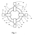
- FIG. 1 a ring network 1 provided with four insertion / extraction multiplexers 2 connected in pairs by links, called resulting, 3 and 4 on which the flow of data transits by respectively turning counterclockwise and clockwise from a shows.
- Each insertion / extraction multiplexer 2 is also connected by links 5, referred to as tributaries, to customer equipment 6.
- a multiplexer could be connected to another multiplexer of the same type from another network. Such a multiplexer is then called brewer.
- a multiplexer 2 When it receives a synchronous stream from one of its two neighbors, a multiplexer 2 in extracts the data that is intended for the client equipment to which it is connected and adds to it the data that said customer equipment wants to transmit on the network, then, after synchronous formatting, transmits synchronous flows to its other neighbour.
- two loops are formed by multiplexers, one clockwise, the other in the other meaning. The choice, at the level of a multiplexer, of an arc of a loop rather than the other arc of the other loop for the transmission of data to another multiplexer is realized so that the circuit followed by these data is the shortest.
- the data flows received from the equipment or sent to the equipment are called tributaries. These tributaries can be synchronous or plesiochronous.
- the advantage of the synchronous transfer mode as specified in the SDH hierarchy and in the SONET concept lies in the structure of the frames used which allow the direct extraction and insertion of data in a frame without it is necessary to demultiplex it completely beforehand.
- the STM-n frames are the result of the multiplexing of n STM-1 frames whose they take up the general structure.
- This frame consists of a set of bytes that we can represent a rectangle of 9 rows and 270 columns.
- the first nine columns in this frame contain the so-called section overhead (SOH: Section OverHead) itself containing service information associated with the management of the section of the line, that is to say the part of line between two equipments synchronous.
- SOH overhead is divided into two parts: the overhead RSOH containing regeneration section management information and the MSOH overhead containing the management information of the multiplex sections.
- the first octets form between them a frame alignment word.
- the payload of the frame contains virtual containers that are arranged hierarchically. Specifically, it contains one or more containers higher order VC-4 or VC-3, which contain lower-order containers such as VC-3, VC-2, VC-12 or VC-11 containers.
- the payload of an STM-1 frame contains a so-called administrative unit AU-4 which is the association of a virtual container called VC-4 and a pointer called AU-4 PTR which is in the fourth line of SOH section overhead of the frame.
- the virtual container VC-4 occupies 9 lines of 261 bytes and is also constituted of a part of a Path overHead containing service information of the conduit (that is, the "end-to-end" conduit) associated with this container and its Payload usually called C-4 container.
- the position of the container virtual VC-4 inside an STM-1 frame is not constant, hence the need for AU-4 PTR pointer pointing to the first byte, called J1, of the VC-4 virtual container.
- a C-4 container can be the result a direct projection of the data to be transmitted but it can also be the result of a multiplexing of three groups of TUG-3 tributary units.
- Each TUG-3 group may be a TU-3 tributary unit, an association of one pointer (bytes H1 H2 and H3) and a virtual container VC-3.
- This virtual container VC-3 is then the result of the combination of a C-3 container in which the data to be transmitted are directly projected and, on the other hand, pipe management POH overhead carrying said data.
- Each unit group flowing TUG-3 may also be the result of a multiplexing seven groups of TUG-2 tributary units, which can be either a tributary unit TU-2 coming from a VC-2 virtual container and therefore from a C-2 container, the result of the multiplexing of three tributary units TU-12 each coming from a virtual container VC-12 and therefore a container C-12, again the result of the multiplexing four tributary units TU-11 each from a virtual container VC-11 and therefore a C-11 container.
- a virtual container is the combination of a container and a POH overhead containing information relating to to the transmission conduit of this container.
- Virtual containers VC-4 and VC-3 are said to be of higher order because they do not need to be encapsulated in other virtual containers to be present in a frame STM-n whereas in contrario, the other containers are said of order inferior.
- the ambivalence in this respect of the virtual container VC-3 which can be higher or lower order if it is included in a VC-4 virtual container.
- the plesiochronous rate carried by a C4 container is 140 Mb / s.
- plesiochronous carried by a container C3 is 34 Mb / s while it is 6 Mb / s for a container C2, 2 Mbit / s for a container C12 and 1.5 Mbits / s for a container C11.
- FIG. 2 It has been shown in FIG. 2 the multiplexing of virtual containers C-12 in a STM-1 frame.
- a Lo-POH conduit management overhead is added (Low order - path overhead: lower order conduit overhead) consisting of four bytes V5, J2, N2 and K4 to form a VC-12 virtual container.
- a unit tributary TU-12 is formed by the addition of a pointer formed by the two bytes V1 and V2. It will be noted that the virtual container VC-12 "floats" in the tributary unit TU-12.
- Three tributary units TU-12 are multiplexed to form a group of units tributaries TUG-2.
- tributary units TUG-12 are multiplexed for form a group of tributary units TUG-3 which are three way multiplexed to form a higher order container VC-4.
- An AU-PTR pointer is attached to this higher order container VC-4 to form an AU-4 administrative unit which is encapsulated in the STM-1 frame.
- an insertion / extraction multiplexer is installed at each node and its essential function is to identify the different containers which are contained in the incoming frame, to determine among these those whose data is intended for the client equipment associated with this node, the extract from the frame to switch them to the corresponding tributaries, to add in the frame of new virtual containers in which were projected the data from tributaries from client devices to transmit to other nodes of the network, then transmit each resulting frame to the next node of the network.
- An insertion / extraction multiplexer generally presents the architecture next visible in FIG. 4. It comprises a switching unit 11 each of which bi-directional port is connected to an adaptation unit 12, 13, 14 and 15.
- the unit of switching 11 may be required to switch lower order virtual containers such as virtual containers VC-11, VC-12, VC-2, VC-3 or containers of higher order such as virtual containers VC-4 or VC-3.
- the units 12, 13, 14 and 15 serve to encapsulate the virtual containers of lower order in higher order virtual containers such as VC-4s or VC-3, by positioning the necessary pointers (in particular the pointers V1, V2 of TU-12, the H1, H2, H3 pointers of TU-3), by filling in the bytes of the overhead of POH leads of these VC-4 virtual containers. They also do the treatments inverses in the other direction of transmission.
- the switching unit 11 and the adaptation units 12, 13, 14 and 15 are mounted on one or more printed circuit boards 10, called matrix card (s).
- the insertion / extraction multiplexer still has implementation interfaces frame 21, 31, 41 and 51 whose essential function is to constitute units higher order AU-4 by associating with virtual order containers superior VC-4 or VC-3 that they respectively receive adaptation units 12, 13, 14 and 15 pointers AU-4 PTR to said higher order virtual containers and to project these AU-4 administrative units into STM-n frames by establishing the SOH related section overheads.
- the functions inverses are implemented in the interfaces 21, 31, 41 and 51.
- the resulting physical interfaces 22 and 32 interfaces to optical signals for optical fibers.
- the physical interfaces of tributaries 42 and 32 may be interfaces to electrical signals, for example for twisted pairs, coaxial cables, etc. But, it could also be from interfaces to optical signals.
- the framing interfaces 21, 31, 41 and 51 as well as the physical interfaces 22, 32, 42, and 52 are respectively mounted on the same printed circuit boards 20, 30, 40 and 50, referred to as either resulting board (for boards 20, 30) or tributary map (for maps 40 and 50).
- Such an architecture has the advantage of being modular having as point common VC-4 virtual container.
- the first is a relatively high complexity due to the number of cards needed to interconnect with all the interconnection constraints that this entails (number of significant wires, relatively high frequency of signals passing card to another, etc.).
- the matrix card is doubled.
- the double can be implemented to re-establish communications that have been momentarily interrupted. That being so, in the architecture described in FIG. 4, the redundancy of SDH processing functions is partial. Indeed, the framing STM-n which is operated in the cards 20, 30, 40 is not doubled.
- the standard provides two bytes, called E1 and F1, provided for service channel channels between sections of regeneration, for example for data or for the telephone. These channels are each 64kbit / s. Likewise, three bytes D1, D2 and D3 are provided which open a channel of data, called DCC (Data Communication Channel). data) for 192 kbit / s network management. These channels of service road and management are called in the following description, communication channels.
- these communication channels E1, F1 and DCC which are present only at the level of the STM-n frames are treated by the interfaces 21, 31, 41 and 51.
- all the signals passing through these channels are not necessarily treated at the place and time.
- the purpose of the present invention is therefore to provide a new architecture of add / drop multiplexer that does not have the disadvantages of the architecture that is described above in connection with FIG. 4.
- the present invention relates to equipment for multiplexing and routing data flow in synchronous transfer mode, such an insertion / extraction multiplexer, a terminal multiplexer, a repeater or a brewer, said data streams being in the form of frames being of type SDH (Synchronous Digital Hierarchy), either of type SONET (Synchronous Optical Network), said frames comprising at least one higher-order virtual container in which virtual containers are inserted of a lower order, said equipment comprising a switching matrix for the routing said lower order virtual containers or the virtual container (s) of higher order, means for inserting / extracting said virtual command containers lower and upper in frames, and physical interfaces.
- SDH Synchronous Digital Hierarchy
- SONET Synchronous Optical Network
- this equipment is characterized in that said switching matrix and said insertion / extraction means are mounted on the same printed circuit board, called matrix board, to which are connected physical interfaces in the form of printed circuit boards.
- said frames in the case where said frames have header overhead in which are inserted bytes of communication channels, it comprises means for processing said bytes of communication channels, said means being present on said matrix card.
- said means are provided for extracting and selecting said bytes of necessary communication channels and rerout those who are not.
- said matrix card is duplicated.
- the invention comprises two setting units in frame which are connected to input / output ports supporting flows of resulting and two framing units that are connected to input / output ports supporting tributary flow, each of said input / output ports supporting synchronous frames, said framing units being provided for performing insertion and extraction of lower order containers and the higher order container (s), each unit of framing being connected to a port of said switching matrix.
- each processing circuit comprising a circuit of processing synchronous frames received on an input port of said circuit for delivering on an output port, in the form of pseudo-frames, the virtual containers they contain, a switching matrix to extract, pseudo-frames present on its input ports, the virtual containers intended to be transmitted on an output port synchronous circuit and deliver them in the form of a pseudo-frame, a circuit of processing said pseudo fields delivered by said switching matrix for delivering synchronous frames on said synchronous output port of said circuit, three pseudo-frame input ports of a circuit being respectively connected to the ports of output of the other three circuits, the fourth pseudo-frame input port of a circuit being connected to the fourth output port of the same circuit.
- each processing circuit includes a transmitting section and a receiving section, said processing circuit has a loopback circuit placed in the emission section downstream of the switching matrix after the processing of the administrative unit (s) and, in the receiving section, downstream of the input port before the processing of said one or more administrative units.
- each processing circuit includes means for inserting and extracting bytes of the channels of communication.
- This multiplexer comprises a unit 110, each bi-directional port of which is connected to control units frame 120, 130, 140 and 150 whose essential function encapsulation in a STM-n frame, in a direction of transmission, and the decapsulation of a frame STM-n, in the other direction of transmission, virtual containers of lower order such virtual containers VC-11, VC-12, VC-2, VC3 or higher order containers such as VC-4 or VC-3 containers processed by the switching unit 110.
- This switching unit 110 and the framing units 120, 130, 140 and 150 are mounted on the same circuit board 100, also called matrix card.
- the multiplexer of the present invention also includes interfaces 200, 300, 400 and 500 which receive the signals in the form of frames STM-n of the matrix card 100, deliver signals compatible with the links results (interfaces 200 and 300) and tributary links (interfaces 400 and 500). They act in reverse in the other direction of transmission. It can be interfaces to optical signals for optical fibers, or to high electrical signals debit. For physical interfaces of tributary 400 and 500, it may be an interface to electrical signals, for example for twisted pairs, cables coaxial, etc. or to optical signals.
- the resulting structure is more compact, on the one hand, because of better possible integration of the matrix card 100, and, on the other hand, the fact that the interfaces 200, 300, 400 and 500 are elements in themselves of relatively small dimensions.
- This architecture also allows greater flexibility in the choice of physical interfaces 200, 300, 400 and 500 since they only interface signals carrying STM-n frames which are normalized.
- Another advantage results from the simplification of the signal flows exchanged between the matrix card 100 and the physical cards 200, 300, 400 and 500. Indeed, while in the architecture of the prior art, they are virtual containers VC-4 which are transmitted to the resulting or tributary cards, requiring not only data but also for accompanying signals, according to the invention these are STM-n frames that are transmitted to the physical cards, which does not require only that the wires to the transmission of these frames in number less than the number of wires necessary for the transmission of VC-4 virtual containers.
- FIG. 6 It is shown in FIG. 6 a ring network identical to that of FIG. 1 but for which one of the links 3, in this case the link 3b, is sectioned.
- the user of the equipment 6a wants to transmit data to the user of the equipment 6c via the links 3a and 3b.
- these data passing through the multiplexer 2b are switched, in the multiplexer 2 upstream of the sectioning, in this case the multiplexer 2b, on the link 4a and then transit via the multiplexers 2a and 2d to the multiplexer 2c where they are extracted from the STM-n frames to be delivered on the client equipment 6c.
- ITU-T Flow failover must be performed according to G.783 and G.841 standards.
- ITU-T referred to above, at AU-4 administrative unit level. These not only incorporate virtual VC-4 containers but also the pointer AU-4 PTR which is in the SOH overhead of the STM-n frame. These units AU-4 are therefore processed at the STM-n frame.
- the invention makes the implementation of the so-called MS SPRING protection function conform to ITU-T G.783 and G.841, discussed above, in contrast to the architectures of the prior art where this implementation is generally carried out only at the VC-4 level.
- the invention solves this problem insofar as the processing functions of the AU-4 administrative unit are made on the matrix card which is duplicated.
- FIG. 7 a simplified synoptic diagram of a matrix card which can be used in an architecture according to the present invention.
- This card matrix is built around four identical processing circuits, for example each consisting of a specific integrated circuit of the ASIC type (Application-Specific Integrated Circuit), a simplified block diagram of which is shown in FIG. 8.
- ASIC Application-Specific Integrated Circuit
- a circuit 600 comprises four input ports 601a through 601d and four output ports 602a through 602d for pseudo-frames of the STM-n type containing ordered order virtual containers lower, for example virtual VC-12 and higher order containers such as virtual containers VC-4 or VC-3.
- ordered order virtual containers lower, for example virtual VC-12 and higher order containers such as virtual containers VC-4 or VC-3.
- frames few frames that have the structure of the STM-n frames but which are not completely example in RSOH and MSOH overheads.
- virtual containers that they contain are aligned, that is, their pointers have values predetermined.
- the circuit 600 further comprises a synchronous output port 603 and a port synchronous input 604 for the transmission and reception of synchronous frames, by example STM-n.
- Each port 603 and 604 has a link 603a, 604a for data and a link 603b, 604b for the clock signal.
- the circuit 600 has for each port 601a to 601d, 602a to 602d, 603, 604 an adaptation interface 611, 612, 613 and 614.
- the circuit 600 comprises a switching matrix 620 of four ports to one whose function is to extract pseudo-frames present on its four ports the virtual containers to be transmitted on the synchronous output port 603, to form a pseudo-frame containing them and direct this pseudo-frame towards its port Release.
- circuit 630 for building the POH overhead of the VC-4 higher order virtual containers that will be contained in the STM-n frame which will be issued, a circuit 631 of construction of or administrative units AU-4 by establishing the corresponding pointer (s) AU-4 PTR, a multiplexing overhead header construction circuit 632 MSOH containing management information dedicated to multiplex sections (section of which at least one end is a multiplexer) and a circuit 633 of RSOH regeneration header overhead construction containing the information of management dedicated to regeneration sections (section between two systems of regeneration). Note that this last circuit 633 is provided with an input for the insertion of the data relating to the communication channels (E1, F1 and DCC), data received on a suitable port 634 and processed by a circuit 635.
- E1, F1 and DCC data received on a suitable port 634 and processed by a circuit 635.
- the circuit 600 further includes a header overhead processing circuit 643.
- RSOH regeneration system which also delivers data relating to the communication (E1, F1 and DCC) which are delivered via a processing circuit 645 on a port 644. It still has a 642 header overhead processing circuit.
- multiplexing MSOH multiplexing MSOH
- a POH overhead processing circuit 640 of the virtual container (s) higher order VC-4 a circuit 646 for processing the pointer of the tributary units, for example tributary units TU-12, contained in the higher-order virtual containers VC-4
- a duplication circuit 648 for delivering, via the adaptation interface 612, on the output ports 602a to 602d, the same pseudo-frame containing all the virtual containers that were contained in the STM-n frame on the port of entry synchronous 604.
- the circuit 600 further comprises a loopback circuit 650 which has the function of to deliver at the entrance of the circuit 641 the flow constituted of or of the administrative units AU-4 at the output of circuit 631 only when the resulting tie is cut downstream of the circuit 600, otherwise this flow is normally delivered to the circuit 632.
- the circuit of 650 loopback ensures the MS SPRING function.
- the loopback circuit 650 is placed in the section transmission, downstream of the switching matrix 620 after the insertion of the pointer AU-PTR of the AU-4 administrative unit and, in the reception section, downstream of the port input 604 before processing this unit's AU-PTR pointer Administrative AU-4.
- the resulting loopback thus intervenes at the level of the AU-4 administrative units. It will also be noticed that this loopback intervenes also from the transmitting section to the receiving section of circuit 600 and after the switching matrix 620.
- the looped stream is assembled into one or more administrative units AU-4 in the transmitting section of circuit 600, then in the receiving section, is disassembled into its virtual containers which are then realigned.
- the AU-4 administrative unit will normally be again reconstituted in another circuit 600 identical before being issued in a STM-n frame.
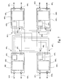
- FIG. 7 it can be seen how four processing circuits 600 1 , 600 2 , 600 3 and 600 4 are assembled to form an insertion / extraction multiplexer.
- 600 1 , 600 2 , 600 3 and 600 4 are recognized in each circuit, its switching matrix 620 1, 620 2, 620 3 and 620 4 , its STM-n tracing and processing circuits that the It has been represented by a single functional box 660 1 , 660 2 , 660 3 and 6604.
- ports 603 1 to 603 4 and 604 1 to 604 4 input and output of STM-n frames and the ports 601 1 to 601 4 and 602 1 to 602 4 input and output pseudo -trames.
- the ports 603 1 , 604 1 and 603 2 , 604 2 form the input and output ports of the respectively West and East results whereas the ports 603 3 , 604 3 and 603 4 , 604 4 form the input ports and output of tributaries respectively West and East of the matrix card.
- connection of the four circuits 600 is as follows: three ports 601a, 601b and 601c input pseudo-frames of a circuit 600 are respectively connected to the ports output 602 of the other three circuits 600.
- the fourth port 601d pseudo-frame input a circuit 600 is connected to the fourth output port 602 of the same circuit 600.
Landscapes
- Engineering & Computer Science (AREA)
- Computer Networks & Wireless Communication (AREA)
- Signal Processing (AREA)
- Time-Division Multiplex Systems (AREA)
- Data Exchanges In Wide-Area Networks (AREA)
Abstract
Description
Claims (7)
- Equipement de multiplexage et de routage de flux de données en mode de transfert synchrone, tel qu'un multiplexeur d'insertion/extraction, un multiplexeur terminal, un répéteur ou un brasseur, lesdits flux de données se présentant sous la forme de trames soit de type SDH (Synchronous Digital Hierarchy : Hiérarchie numérique synchrone), soit de type SONET (Synchronous Optical Network), lesdites trames comportant au moins un container virtuel (VC-4) d'ordre supérieur dans lequel sont insérés des containers virtuels d'ordre inférieur (VC-12, VC-2, VC-11, VC-3.), ledit équipement comprenant une matrice de commutation pour le routage desdits containers virtuels d'ordre inférieur ou du ou des containers virtuels d'ordre supérieur, des moyens d'insertion/extraction desdits containers virtuels d'ordres inférieur et supérieur dans des trames, et des interfaces physiques, caractérisé en ce que lesdits moyens d'insertion/extraction comprennent deux unités de mise en trame (120, 130) qui sont reliées à des ports d'entrée/sortie supportant des flux de résultant et deux unités de mise en trame (140, 150) qui sont reliées à des ports d'entrée/sortie supportant des flux d'affluent, chacun desdits ports d'entrée/sortie supportant des trames synchrones, chaque unité de mise en trame (120, 130, 140 et 150) étant reliée à un port de ladite matrice de commutation (110), ladite matrice de commutation et lesdites unités de mise en trame (120, 130, 140, 150) étant montées sur une même carte de circuit imprimé, dite carte matrice, à laquelle sont connectées des interfaces physiques (200, 300, 400, 500) sous la forme de cartes de circuit imprimé et respectivement reliées auxdits ports d'entrée/sortie desdites unités de mise en trame (120, 130, 140, 150).
- Equipement de multiplexage et de routage selon la revendication 1, lesdites trames comportant un surdébit d'en-tête de section dans lequel sont insérés des octets de canaux de communication, caractérisé en ce qu'il comporte des moyens pour traiter lesdits octets de canaux de communication, lesdits moyens étant présents sur ladite carte matrice.
- Equipement de multiplexage et de routage selon la revendication 2, caractérisé en ce que lesdits moyens sont prévus pour extraire et sélectionner lesdits octets de canaux de communication nécessaires et rerouter ceux qui ne le sont pas.
- Equipement de multiplexage et de routage selon une des revendications précédentes, caractérisé en ce que ladite carte matrice est dupliquée.
- Equipement de multiplexage et de routage de flux de données selon une des revendications précédentes, du type multiplexeur d'insertion/extraction ou brasseur, caractérisé en ce qu'il est constitué de quatre circuits de traitement identiques, chaque circuit de traitement comportant un circuit de traitement des trames synchrones reçues sur un port d'entrée dudit circuit pour délivrer sur un port de sortie, sous forme de pseudo-trames, les containers virtuels qu'elles contiennent, une matrice de commutation pour extraire, des pseudo-trames présentes sur ses ports d'entrée, les containers virtuels destinés à être émis sur un port de sortie synchrone (603) dudit circuit et les délivrer sous la forme d'une pseudo-trame, un circuit de traitement desdites pseudo-trames délivrées par ladite matrice de commutation pour délivrer des trames synchrones sur ledit port de sortie synchrone dudit circuit, trois ports (601 a, 601b et 601c) d'entrée de pseudo-trames d'un circuit (600) étant respectivement reliés aux ports de sortie (602) des trois autres circuits (600), le quatrième port (601d) d'entrée de pseudo-trames d'un circuit (600) étant relié au quatrième port de sortie (602) du même circuit (600).
- Equipement de multiplexage et de routage selon la revendication 5, caractérisé en ce que chaque circuit de traitement comporte une section d'émission et une section de réception, ledit circuit de traitement comportant un circuit de rebouclage placé, dans la section émission, en aval de la matrice de commutation après le traitement de la ou des unités administratives (AU-4) et, dans la section réception, en aval du port d'entrée avant le traitement de ladite ou desdites unités administratives (AU-4).
- Equipement de multiplexage et de routage selon la revendication 5 ou 6, caractérisé en ce que chaque circuit de traitement comporte des moyens d'insertion et d'extraction des octets des canaux de communication.
Applications Claiming Priority (2)
| Application Number | Priority Date | Filing Date | Title |
|---|---|---|---|
| FR0209708 | 2002-07-26 | ||
| FR0209708A FR2842972B1 (fr) | 2002-07-26 | 2002-07-26 | Equipement de multiplexage et routage de flux de donnees en mode de transfert synchrone ou flux synchrones |
Publications (2)
| Publication Number | Publication Date |
|---|---|
| EP1385287A1 true EP1385287A1 (fr) | 2004-01-28 |
| EP1385287B1 EP1385287B1 (fr) | 2006-01-25 |
Family
ID=29797687
Family Applications (1)
| Application Number | Title | Priority Date | Filing Date |
|---|---|---|---|
| EP20030291841 Expired - Lifetime EP1385287B1 (fr) | 2002-07-26 | 2003-07-25 | Equipement de multiplexage et routage de flux de données en mode de transfert synchrone ou flux synchrones |
Country Status (3)
| Country | Link |
|---|---|
| EP (1) | EP1385287B1 (fr) |
| DE (1) | DE60303351T2 (fr) |
| FR (1) | FR2842972B1 (fr) |
Citations (1)
| Publication number | Priority date | Publication date | Assignee | Title |
|---|---|---|---|---|
| US5267239A (en) * | 1989-08-31 | 1993-11-30 | Siemens Aktiengesellschaft | Cross-connect method for STM-1 signals of the synchronous digital multiplex hierarchy |
-
2002
- 2002-07-26 FR FR0209708A patent/FR2842972B1/fr not_active Expired - Lifetime
-
2003
- 2003-07-25 EP EP20030291841 patent/EP1385287B1/fr not_active Expired - Lifetime
- 2003-07-25 DE DE2003603351 patent/DE60303351T2/de not_active Expired - Lifetime
Patent Citations (1)
| Publication number | Priority date | Publication date | Assignee | Title |
|---|---|---|---|---|
| US5267239A (en) * | 1989-08-31 | 1993-11-30 | Siemens Aktiengesellschaft | Cross-connect method for STM-1 signals of the synchronous digital multiplex hierarchy |
Non-Patent Citations (3)
| Title |
|---|
| BASCH B ET AL: "OC-12 Crossconnect For The Vistanet Gigabit Network", OPTICAL MICROWAVE INTERACTIONS/VISIBLE SEMICONDUCTOR LASERS/IMPACT OF FIBER NONLINEARITIES ON LIGHTWAVE SYSTEMS/HYBRID OPTOELECTRONIC INTEGRATION AND PACKAGING/GIGABIT NETWORKS., LEOS 1993 SUMMER TOPICAL MEETING DIGEST ON SANTA BARBARA, CA, USA 19-30, 19 July 1993 (1993-07-19), pages G47 - G48, XP010068833, ISBN: 0-7803-1284-8 * |
| KOZAK A: "Applications of multichip modules for high speed communications interfaces", PROCEEDINGS OF THE MULTI CHIP MODULE CONFERENCE (MCMC). SANTA CRUZ, MAR. 18 - 20, 1992, LOS ALAMITOS, IEEE COMP. SOC. PRESS, US, vol. CONF. 1, 18 March 1992 (1992-03-18), pages 16 - 18, XP010028000, ISBN: 0-8186-2725-5 * |
| THALMANN M ET AL: "A single-chip solution for an ADM-1/TMX-1 SDH telecommunication node element", ASIC/SOC CONFERENCE, 1999. PROCEEDINGS. TWELFTH ANNUAL IEEE INTERNATIONAL WASHINGTON, DC, USA 15-18 SEPT. 1999, PISCATAWAY, NJ, USA,IEEE, US, 15 September 1999 (1999-09-15), pages 147 - 151, XP010360249, ISBN: 0-7803-5632-2 * |
Also Published As
| Publication number | Publication date |
|---|---|
| DE60303351D1 (de) | 2006-04-13 |
| FR2842972A1 (fr) | 2004-01-30 |
| EP1385287B1 (fr) | 2006-01-25 |
| FR2842972B1 (fr) | 2004-12-17 |
| DE60303351T2 (de) | 2006-08-17 |
Similar Documents
| Publication | Publication Date | Title |
|---|---|---|
| US7822022B2 (en) | Multi-rate, multi-protocol, multi-port line interface for a multiservice switching platform | |
| US7106968B2 (en) | Combined SONET/SDH and OTN architecture | |
| EP1737147B1 (fr) | Procede de transmission de signaux de trafic a faible debit dans un reseau de transmission optique et dispositif correspondant | |
| US6816496B2 (en) | Frame based data transmission over synchronous digital hierarchy network | |
| CA2154995C (fr) | Procede d'entrelacement et de desentrelacement de trames sdh et systeme correspondant | |
| US9020345B2 (en) | Method and system for establishing end-to-end service and optical transport network | |
| US20040156390A1 (en) | Efficient framing procedure for variable length packets | |
| JP2005531988A (ja) | トランスペアレントでフレキシブルな連結 | |
| EP1405448B1 (fr) | Procede et dispositif de transmission de donnees synchrones | |
| US7362777B2 (en) | Concatenated transmission of synchronous data | |
| US20030152079A1 (en) | Method and apparatus for transporting a SDH/SONET client signal as a service | |
| Scholten et al. | Data transport applications using GFP | |
| JP5739162B2 (ja) | 任意速度のクライアント信号についての二重非同期マッピング | |
| EP1385287B1 (fr) | Equipement de multiplexage et routage de flux de données en mode de transfert synchrone ou flux synchrones | |
| US20020191617A1 (en) | System and method for transporting channelized ethernet over SONET/SDH | |
| JP3734762B2 (ja) | Wdm装置 | |
| JP2001333440A (ja) | 光ネットワークエレメント | |
| US7016378B1 (en) | Method and system for automatically provisioning an overhead byte | |
| US20030081596A1 (en) | Intelligent optical network linecard with localized processing functionality | |
| CA2287422A1 (fr) | Dispositif de commutation de circuits dans un reseau de telecommunications | |
| EP0629100B1 (fr) | Procédé et agencement pour une transmission en mode cellule d'informations fournies et restituées en mode circuit à bande étroite | |
| EP0814580A1 (fr) | Multiplexeur hybride | |
| EP1401132A1 (fr) | Procédé d'établissement de signaux d'alignement destinés à être utilisés pour l'extraction de containers d'une trame synchrone, bus supportant de tels signaux d'alignement et signaux d'alignement | |
| EP1889388A1 (fr) | Procede et systeme de transmission d'un rythme de synchronisation sur un lien reseau de technologie ethernet et leur applications | |
| EP1597871B1 (fr) | Systeme de transmission de trains de donnees numeriques plesiochrones dans un reseau ethernet virtuel |
Legal Events
| Date | Code | Title | Description |
|---|---|---|---|
| PUAI | Public reference made under article 153(3) epc to a published international application that has entered the european phase |
Free format text: ORIGINAL CODE: 0009012 |
|
| AK | Designated contracting states |
Kind code of ref document: A1 Designated state(s): AT BE BG CH CY CZ DE DK EE ES FI FR GB GR HU IE IT LI LU MC NL PT RO SE SI SK TR |
|
| AX | Request for extension of the european patent |
Extension state: AL LT LV MK |
|
| 17P | Request for examination filed |
Effective date: 20040414 |
|
| 17Q | First examination report despatched |
Effective date: 20040716 |
|
| AKX | Designation fees paid |
Designated state(s): DE GB IT |
|
| GRAP | Despatch of communication of intention to grant a patent |
Free format text: ORIGINAL CODE: EPIDOSNIGR1 |
|
| GRAS | Grant fee paid |
Free format text: ORIGINAL CODE: EPIDOSNIGR3 |
|
| GRAA | (expected) grant |
Free format text: ORIGINAL CODE: 0009210 |
|
| AK | Designated contracting states |
Kind code of ref document: B1 Designated state(s): DE GB IT |
|
| REG | Reference to a national code |
Ref country code: GB Ref legal event code: FG4D Free format text: NOT ENGLISH |
|
| GBT | Gb: translation of ep patent filed (gb section 77(6)(a)/1977) |
Effective date: 20060125 |
|
| REF | Corresponds to: |
Ref document number: 60303351 Country of ref document: DE Date of ref document: 20060413 Kind code of ref document: P |
|
| PLBE | No opposition filed within time limit |
Free format text: ORIGINAL CODE: 0009261 |
|
| STAA | Information on the status of an ep patent application or granted ep patent |
Free format text: STATUS: NO OPPOSITION FILED WITHIN TIME LIMIT |
|
| 26N | No opposition filed |
Effective date: 20061026 |
|
| REG | Reference to a national code |
Ref country code: GB Ref legal event code: 732E Free format text: REGISTERED BETWEEN 20090319 AND 20090325 |
|
| REG | Reference to a national code |
Ref country code: GB Ref legal event code: 732E Free format text: REGISTERED BETWEEN 20090326 AND 20090401 |
|
| REG | Reference to a national code |
Ref country code: DE Ref legal event code: R082 Ref document number: 60303351 Country of ref document: DE Representative=s name: PATENT- UND RECHTSANWAELTE HANSMANN & VOGESER, DE Ref country code: DE Ref legal event code: R082 Ref document number: 60303351 Country of ref document: DE |
|
| REG | Reference to a national code |
Ref country code: DE Ref legal event code: R081 Ref document number: 60303351 Country of ref document: DE Owner name: SAGEMCOM SAS, FR Free format text: FORMER OWNER: SAGEM S.A., PARIS, FR Effective date: 20120120 Ref country code: DE Ref legal event code: R081 Ref document number: 60303351 Country of ref document: DE Owner name: SAGEMCOM ENERGY & TELECOM SAS, FR Free format text: FORMER OWNER: SAGEM S.A., PARIS, FR Effective date: 20120120 |
|
| REG | Reference to a national code |
Ref country code: DE Ref legal event code: R082 Ref document number: 60303351 Country of ref document: DE Representative=s name: PATENT- UND RECHTSANWAELTE HANSMANN & VOGESER, DE Effective date: 20120120 Ref country code: DE Ref legal event code: R081 Ref document number: 60303351 Country of ref document: DE Owner name: SAGEMCOM SAS, FR Free format text: FORMER OWNER: SAGEM TELECOMMUNICATIONS S. A., PARIS, FR Effective date: 20121112 Ref country code: DE Ref legal event code: R081 Ref document number: 60303351 Country of ref document: DE Owner name: SAGEMCOM ENERGY & TELECOM SAS, FR Free format text: FORMER OWNER: SAGEM TELECOMMUNICATIONS S. A., PARIS, FR Effective date: 20121112 Ref country code: DE Ref legal event code: R082 Ref document number: 60303351 Country of ref document: DE Representative=s name: WEICKMANN & WEICKMANN, DE Effective date: 20120120 Ref country code: DE Ref legal event code: R082 Ref document number: 60303351 Country of ref document: DE Representative=s name: WEICKMANN & WEICKMANN PATENTANWAELTE - RECHTSA, DE Effective date: 20120120 Ref country code: DE Ref legal event code: R082 Ref document number: 60303351 Country of ref document: DE Representative=s name: WEICKMANN & WEICKMANN PATENT- UND RECHTSANWAEL, DE Effective date: 20120120 |
|
| REG | Reference to a national code |
Ref country code: DE Ref legal event code: R082 Ref document number: 60303351 Country of ref document: DE Representative=s name: PATENT- UND RECHTSANWAELTE HANSMANN & VOGESER, DE |
|
| REG | Reference to a national code |
Ref country code: GB Ref legal event code: 732E Free format text: REGISTERED BETWEEN 20130221 AND 20130227 |
|
| REG | Reference to a national code |
Ref country code: DE Ref legal event code: R081 Ref document number: 60303351 Country of ref document: DE Owner name: SAGEMCOM SAS, FR Free format text: FORMER OWNER: SAGEMCOM ENERGY & TELECOM SAS, RUEIL-MALMAISON, FR Effective date: 20130129 Ref country code: DE Ref legal event code: R082 Ref document number: 60303351 Country of ref document: DE Representative=s name: PATENT- UND RECHTSANWAELTE HANSMANN & VOGESER, DE Effective date: 20130129 Ref country code: DE Ref legal event code: R081 Ref document number: 60303351 Country of ref document: DE Owner name: SAGEMCOM ENERGY & TELECOM SAS, FR Free format text: FORMER OWNER: SAGEMCOM ENERGY & TELECOM SAS, RUEIL-MALMAISON, FR Effective date: 20130129 Ref country code: DE Ref legal event code: R082 Ref document number: 60303351 Country of ref document: DE Representative=s name: WEICKMANN & WEICKMANN, DE Effective date: 20130129 Ref country code: DE Ref legal event code: R082 Ref document number: 60303351 Country of ref document: DE Representative=s name: WEICKMANN & WEICKMANN PATENTANWAELTE - RECHTSA, DE Effective date: 20130129 Ref country code: DE Ref legal event code: R082 Ref document number: 60303351 Country of ref document: DE Representative=s name: WEICKMANN & WEICKMANN PATENT- UND RECHTSANWAEL, DE Effective date: 20130129 |
|
| REG | Reference to a national code |
Ref country code: DE Ref legal event code: R082 Ref document number: 60303351 Country of ref document: DE Representative=s name: PATENT- UND RECHTSANWAELTE HANSMANN & VOGESER, DE |
|
| REG | Reference to a national code |
Ref country code: DE Ref legal event code: R081 Ref document number: 60303351 Country of ref document: DE Owner name: SAGEMCOM ENERGY & TELECOM SAS, FR Free format text: FORMER OWNER: SAGEMCOM SAS, RUEIL MALMAISON, FR Effective date: 20130412 Ref country code: DE Ref legal event code: R082 Ref document number: 60303351 Country of ref document: DE Representative=s name: PATENT- UND RECHTSANWAELTE HANSMANN & VOGESER, DE Effective date: 20130412 Ref country code: DE Ref legal event code: R082 Ref document number: 60303351 Country of ref document: DE Representative=s name: WEICKMANN & WEICKMANN, DE Effective date: 20130412 Ref country code: DE Ref legal event code: R082 Ref document number: 60303351 Country of ref document: DE Representative=s name: WEICKMANN & WEICKMANN PATENTANWAELTE - RECHTSA, DE Effective date: 20130412 Ref country code: DE Ref legal event code: R082 Ref document number: 60303351 Country of ref document: DE Representative=s name: WEICKMANN & WEICKMANN PATENT- UND RECHTSANWAEL, DE Effective date: 20130412 |
|
| REG | Reference to a national code |
Ref country code: DE Ref legal event code: R082 Ref document number: 60303351 Country of ref document: DE Representative=s name: WEICKMANN & WEICKMANN PATENTANWAELTE - RECHTSA, DE Ref country code: DE Ref legal event code: R082 Ref document number: 60303351 Country of ref document: DE Representative=s name: WEICKMANN & WEICKMANN PATENT- UND RECHTSANWAEL, DE |
|
| PGFP | Annual fee paid to national office [announced via postgrant information from national office to epo] |
Ref country code: IT Payment date: 20220621 Year of fee payment: 20 Ref country code: GB Payment date: 20220621 Year of fee payment: 20 |
|
| PGFP | Annual fee paid to national office [announced via postgrant information from national office to epo] |
Ref country code: DE Payment date: 20220621 Year of fee payment: 20 |
|
| REG | Reference to a national code |
Ref country code: DE Ref legal event code: R071 Ref document number: 60303351 Country of ref document: DE |
|
| REG | Reference to a national code |
Ref country code: GB Ref legal event code: PE20 Expiry date: 20230724 |
|
| PG25 | Lapsed in a contracting state [announced via postgrant information from national office to epo] |
Ref country code: GB Free format text: LAPSE BECAUSE OF EXPIRATION OF PROTECTION Effective date: 20230724 |