EP1385246A2 - Conduit insert for optical fiber cable - Google Patents
Conduit insert for optical fiber cable Download PDFInfo
- Publication number
- EP1385246A2 EP1385246A2 EP03023245A EP03023245A EP1385246A2 EP 1385246 A2 EP1385246 A2 EP 1385246A2 EP 03023245 A EP03023245 A EP 03023245A EP 03023245 A EP03023245 A EP 03023245A EP 1385246 A2 EP1385246 A2 EP 1385246A2
- Authority
- EP
- European Patent Office
- Prior art keywords
- set forth
- cable
- flexible
- apparatus set
- flexible material
- Prior art date
- Legal status (The legal status is an assumption and is not a legal conclusion. Google has not performed a legal analysis and makes no representation as to the accuracy of the status listed.)
- Granted
Links
Images



Classifications
-
- G—PHYSICS
- G02—OPTICS
- G02B—OPTICAL ELEMENTS, SYSTEMS OR APPARATUS
- G02B6/00—Light guides; Structural details of arrangements comprising light guides and other optical elements, e.g. couplings
- G02B6/44—Mechanical structures for providing tensile strength and external protection for fibres, e.g. optical transmission cables
-
- H—ELECTRICITY
- H02—GENERATION; CONVERSION OR DISTRIBUTION OF ELECTRIC POWER
- H02G—INSTALLATION OF ELECTRIC CABLES OR LINES, OR OF COMBINED OPTICAL AND ELECTRIC CABLES OR LINES
- H02G9/00—Installations of electric cables or lines in or on the ground or water
- H02G9/06—Installations of electric cables or lines in or on the ground or water in underground tubes or conduits; Tubes or conduits therefor
-
- D—TEXTILES; PAPER
- D03—WEAVING
- D03D—WOVEN FABRICS; METHODS OF WEAVING; LOOMS
- D03D1/00—Woven fabrics designed to make specified articles
- D03D1/0035—Protective fabrics
- D03D1/0043—Protective fabrics for elongated members, i.e. sleeves
-
- G—PHYSICS
- G02—OPTICS
- G02B—OPTICAL ELEMENTS, SYSTEMS OR APPARATUS
- G02B6/00—Light guides; Structural details of arrangements comprising light guides and other optical elements, e.g. couplings
- G02B6/44—Mechanical structures for providing tensile strength and external protection for fibres, e.g. optical transmission cables
- G02B6/4439—Auxiliary devices
- G02B6/4459—Ducts; Conduits; Hollow tubes for air blown fibres
-
- G—PHYSICS
- G02—OPTICS
- G02B—OPTICAL ELEMENTS, SYSTEMS OR APPARATUS
- G02B6/00—Light guides; Structural details of arrangements comprising light guides and other optical elements, e.g. couplings
- G02B6/46—Processes or apparatus adapted for installing or repairing optical fibres or optical cables
- G02B6/50—Underground or underwater installation; Installation through tubing, conduits or ducts
- G02B6/508—Fixation devices in ducts for drawing cables
-
- H—ELECTRICITY
- H02—GENERATION; CONVERSION OR DISTRIBUTION OF ELECTRIC POWER
- H02G—INSTALLATION OF ELECTRIC CABLES OR LINES, OR OF COMBINED OPTICAL AND ELECTRIC CABLES OR LINES
- H02G3/00—Installations of electric cables or lines or protective tubing therefor in or on buildings, equivalent structures or vehicles
- H02G3/02—Details
- H02G3/04—Protective tubing or conduits, e.g. cable ladders or cable troughs
- H02G3/0462—Tubings, i.e. having a closed section
- H02G3/0481—Tubings, i.e. having a closed section with a circular cross-section
-
- H—ELECTRICITY
- H02—GENERATION; CONVERSION OR DISTRIBUTION OF ELECTRIC POWER
- H02G—INSTALLATION OF ELECTRIC CABLES OR LINES, OR OF COMBINED OPTICAL AND ELECTRIC CABLES OR LINES
- H02G9/00—Installations of electric cables or lines in or on the ground or water
- H02G9/06—Installations of electric cables or lines in or on the ground or water in underground tubes or conduits; Tubes or conduits therefor
- H02G9/065—Longitudinally split tubes or conduits therefor
Definitions
- the present invention generally relates to tubular conduit of the type that might be employed for the housing of underground cables, such as fiber optic cable, coaxial cable, or the like. More particularly, the present invention relates to a partitioning device, which may be inserted into such a conduit such that the conduit is divided into separate areas. Specifically, the present invention is directed toward an elongated partitioning device which is flexible, such that it may be inserted into a conduit which is already in place, which may already have at least one cable positioned therein, and which may have turns, bends, or the like therein.
- Cable such as fiber optic communication cable
- Cable is often provided underground in great lengths, and may even extend for many miles. It is known in the art to bury the cable in the ground so that the area above ground is not cluttered with the cable and its respective support apparatus. Furthermore, by positioning the cable underground, it is more protected from the weather and other potentially damaging circumstances.
- the conduit is often formed from lengths of polyvinyl chloride tubing or the like, which is laid in the ground. A rope is then blown through the conduit, and the rope in turn is attached to one of the communication cables. By pulling the rope, the cable is drawn through the conduit. Once in place within the conduit, the cable is protected from damage which may be caused by weather, water and the like.
- the device must be capable of being inserted into a conduit that is already in place, which may undulate over many miles, and which may have sharp turns therein.
- the present invention comprises a flexible innerduct structure configured to contain a cable within a conduit.
- the innerduct structure includes a pair of adjacent strip-shaped layers of flexible material that are joined along their longitudinal edges to define a channel through which the cable can extend longitudinally through the innerduct structure between the layers.
- the adjacent layers have differing widths between their longitudinal edges, whereby the wider layer bulges away from the narrower layer to impart an open configuration to the channel.
- Such features relate to the material of which the innerduct structure is formed.
- Such features include the structure of the material, such as a woven structure, and further include properties such as melting point, tensile strength, elongation, coefficient of friction, crimp resistance and compression recovery.
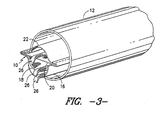
- the reference number 10 represents an insert, which may be referred to as an innerduct, to be inserted in an optical fiber cable conduit 12.
- an innerduct 10 As shown in Fig. 3, a single innerduct 10 is shown in a conduit 12, but it should be understood that multiple innerducts like the innerduct 10 can be inserted in a conduit 12 depending on the diameter of the conduit 12. For example, it is contemplated that three such innerducts can be inserted in a 4" diameter conduit providing nine channels for the insertion of fiber optic cable.
- Each innerduct 10 defines of a plurality of channels 14 which are formed by interconnected layers of fabric 16, 18, 20 and 22, etc.
- each innerduct 10 has three channels 14 formed by the above noted layers 16, 18, 20 and 22 which are interconnected at their opposite longitudinal side edge portions by having the edge portions 25 of the lower layer 16 overlap the edge portions of the other layers and, by sewing 24 or other suitable methods such as ultrasonic welding, connecting the layers 16, 18, 20 and 22 together.
- the fabric material preferably is soft and pliable, allowing the innerduct 10 to be pulled through the conduit 12 without snagging or generating too much heat and also is diverse enough so that the cable in one channel 14 does not contact the cable in the next adjacent channel 14.
- the layers 16, 18, 20 and 22 in the first embodiment are 100% plain woven nylon fabrics having a 520 denier monofilament in both the warp and fill direction woven with a pick and end count of 38.5 which, when finished, has a 40 X 40 pick and end count.
- the fabric has a weight of 6.0 oz. yd. It is understood that the monofilament denier can vary from 200 - 1000 denier and the pick and end could well be altered to provide the desired cover to prevent contact of the fiber optic cables.
- the preferred yarn is 520 denier nylon 6 monofilament but another yarn, such as a 520 denier polyester, can be used so long as it has the desired characteristics.
- the innerduct 10 is preferable constructed in the following manner.
- the fabric layers 16, 18, 20 and 22 are initially woven in long wide shapes and are cut along the warp direction into strips with the center strip 20 being the narrowest, the next adjacent strips 18 and 22 being wider, and the strip 16 being the widest so that when the strips 16-22 are mated and joined at their longitudinal edge portions the channels 14 will be formed by the bulging of the wider strips 16, 18 and 22.
- the innerduct 10 is manufactured in long lengths for insertion in previously installed conduits 12.
- Each layer 16-22 is formed in a correspondingly long length by stitching or otherwise joining successive strips of the fabric material together end to end.
- Pull lines 26, which are preferably woven plastic tapes or plastic ropes, are tied to the optical fiber cables (not shown) at one end and are pulled through the channels 14 by grasping and pulling the lines 26 at the other end.
- the pull lines 26 are preferably placed over the layers 16, 18 and 20 before the layers 16-22 are overlapped and joined at their longitudinal edge portions.
- a single innerduct 10 is inserted in a conduit 12 having an inner diameter of 4".
- the strip-shaped fabric layer 20 is 3" wide, the layers 18 and 22 are 4" wide, and the layer 16 is 6" wide.
- the width of the narrowest layer is thus less than the inner diameter of the conduit 12. This helps to minimize frictional engagement of the innerduct 10 with the conduit 12 when the innerduct 10 is being pulled through the conduit 12.
- the above described innerduct is readily manufactured and provides a structure which allows optical fiber cables to be pulled through without snagging or excessive heat buildup due to friction and does not allow contact or alternation losses between adjacent fiber optic cables in other channels of the insert.
- a flexible innerduct structure 100 comprising a second embodiment of the invention is shown in Fig. 4.
- the innerduct structure 100 in the second embodiment comprises strip-shaped layers of flexible woven material 102, 104, 106 and 108 that are joined along their longitudinal edge portions 110, 112, 114 and 116, respectively, by stitching 118.
- Each pair of adjacent layers defines a respective cable channel 121, 123 or 125.
- the layers in each pair have differing widths between their longitudinal edges such that the wider layer in the pair bulges away from the narrower layer. This imparts open configurations to the channels 121, 123 or 125.
- the open configurations of the channels 121, 123 and 125 in the innerduct 100 facilitate insertion of cables longitudinally through the channels 121, 123 and 125 by the use of respective pull lines 131, 133 and 135. This is because the spacing between the layers 102-108 helps to prevent them from being pulled along with the cables, and thus helps to prevent bunching-up of the innerduct 100 within the conduit under the influence of the cable and pull lines 131-135 moving longitudinally through the channels 121, 123 and 125.
- the cross section of the innerduct 10 is defined by separate strips of fabric material that are interconnected at their longitudinal edge portions to define overlying layers 16, 18, 20 and 22.
- the overlying layers 102, 104, 106 and 108 of the innerduct 100 also are interconnected at their longitudinal edge portions, but are defined by folded sections of a single strip 140 of fabric material. Two, three, four (Fig. 2) or more strips could be used to define overlying layers in accordance with the invention.
- Each strip is one of a plurality of successive strips that are joined together end to end to provide the innerduct with a length that may extend, for example, from three to four miles.
- Fig 5 is a schematic partial view of an optical fiber cable 150 to be installed in an innerduct constructed in accordance with the invention.
- the cable 150 includes a plastic sheath 152 containing a bundle of optical fibers 154.
- each layer of the innerduct that receives the cable 150 is formed of a flexible plastic material that is specified with reference to the plastic sheath 152 so as to have a melting temperature not lower than, and most preferably higher than, the melting temperature of the plastic sheathing material. This helps to ensure that sliding friction will not cause the cable 150 to burn through the innerduct when the cable 150 is being pulled longitudinally through the innerduct.
- the innerduct layers are preferably formed of nylon 6 so as to have a melting temperature of about 220 degrees C.
- the resistance to cable burn-through can also be specified with reference to a pull line duct cutting test substantially similar to the test known as the Bellcore pull line duct cutting test.
- the innerduct layer material is preferably specified such that a 0.25 diameter polypropylene rope will not burn through a test sample of the innerduct structure when pulled through the test sample at 100 feet per minute and 450 pounds tension for at least 90 seconds,
- the innerduct layer material may further be specified with reference to the material of which the pull lines are formed.
- the layer material and the pull line material preferably have respective values of elongation percentage that are substantially equal for a given tensile load. If elongation of the innerduct differs substantially from that of a pull line, one of those structures may lag relative to the other when they are pulled together through a conduit in which they are to be installed together.
- the elongation percentages of the layer material and the pull line material are preferably not greater than about 75 percent at a peak tensile load, i.e., just prior to tensile failure, and are preferably within the range of about 15 to about 60 percent.
- a more preferred range extends from about 25 to about 40 percent.
- nylon 6 is a preferred material and has an elongation of about 40 percent at a peak tensile load.
- Polyester is another preferred material and has an elongation of about 25 percent at a peak tensile load.
- each layer preferably has a longitudinal tensile strength of at least about 12.5 pounds per inch of width.
- the longitudinal tensile strength of each layer may be within the range of about 12.5 to about 300 pounds per inch of width, and more preferably is within the range of about 50 to about 250 pounds per inch of width.
- the longitudinal tensile strength of each layer is most preferably within the range of about 100 to about 200 pounds per inch of width.
- each layer 102, 104, 106 and 108 in the innerduct 100 may be formed of a woven fabric having both warp and fill yarns formed of nylon 6, with a longitudinal tensile strength of about 150 pounds per inch of width.
- the interconnected layers should together provide the innerduct structure, as a whole, with a longitudinal tensile strength of at least about 90 pounds, but may provide a longitudinal tensile strength within the range of about 50 to about 5,000 pounds. A more preferred range is from about 125 to 4,500 pounds, and a range of about 1,250 to about 4,000 pounds is most preferable.
- Fig. 6 is a schematic view of a strip 160 of woven innerduct fabric material for use in accordance with the invention.
- the strip has warp yarns 162 extending along its length and has fill yams 164 extending across its width.
- the fill yarns 164 are flexible but have a degree of rigidity or a resistance to crimping that helps the wider layers of the innerduct to retain their bulged condition relative to the adjacent narrower layers, as shown for example in Fig. 4, without being crimped or creased inward toward the adjacent narrower layers.
- Such crimping or creasing is of less concern in the longitudinal direction of the layers. Therefore, the warp yarns 162 of Fig.
- the 6 may have a crimp resistance that is less than the crimp resistance of the fill yarns 164.
- a crimp resistance that is less than the crimp resistance of the fill yarns 164.
- the warp yarns 162 are formed of polyester, which has a first crimp resistance
- the fill yams 164 are formed of nylon 6, which has a second, greater crimp resistance.
- Polyester is preferably used for the warp yams 162 so as to minimize the elongation differential with the pull lines, which also are preferably formed of polyester.
- the crimp resistance can be expressed in terms of the crimp recovery angle.
- the crimp recovery angle is a measure of the degree to which a sample of the material returns toward a flat unfolded condition after having once been folded 180 degrees about a fold line in accordance with AATCC method 66.
- a particular innerduct layer material constructed in accordance with the invention has heatset polyester warp yarns and nylon 6 fill yarns. That material was found to have a crimp recovery angle of 70 degrees in the warp direction and 135 degrees in the fill direction. A similar material with greige polyester rather than heatset polyester was found to have a crimp recovery angle of 50 degrees in the warp direction and 125 degrees in the fill direction.
- a material having heat set polyester yarns in both the warp and fill directions was found to have a crimp recovery angle of 90 degrees in the warp direction and 75 degrees in the fill direction.
- a similar material having only greige nylon yarns in both the warp and fill directions is found to have a crimp recovery angle 130 degrees in the warp direction and 120 degrees in the fill direction.
- the innerduct layer material should be rigid enough to resist collapsing upon itself or bunching up under the influence of the pull lines and cables, but also should be flexible enough to be pulled easily through turns and undulation in the duct in which it is installed.
- the INDA IST90.3 test procedure is a method of determining the rigidity of the innerduct layer material. In this procedure, a test sample of flexible material is laid out over a slotted surface. A blade is then used to force the material through the slot. The results are expressed in terms of the applied force.
- a strip of innerduct layer material extending longitudinally across the slot will be forced to bend along a transversely extending fold line. Such a strip will preferably have rigidity test results within the range of about 950 to about 1,750 grams.
- a strip of innerduct layer material extending transversely across the slot will be forced to bend about a longitudinally extending fold line, and will preferably have rigidity test results within the range of about 150 to about 750 grams.
- the strip of innerduct layer material will thus have a lesser rigidity across its width.
- the correspondingly greater degree of flexibility across its width helps to avoid creasing and thereby helps the wider layers of the innerduct to retain their bulged condition relative to the adjacent narrower layers, as described above with reference to Fig. 4.
- the strip 160 (Fig. 6) of woven innerduct fabric material has fill yarns 164 that are formed of nylon 6. Such yarns are found to have rigidity test results within the range of about 350 to about 550 grams.
- the warp yarns 162 are formed of polyester. Such yarns are found to have rigidity test results within the range of about 1, 250 to about 1,450 grams.
- the innerduct layer material preferably has a dry static coefficient of friction, based on high density polyethylene on the material with a longitudinal line of action, within the range of about 0.010 to about 0.500. This range is more preferably from about 0.025 to about 0.250, and is preferably from about 0.035 to about 0.100.
- a woven innerduct layer having polyester warp yarns and nylon 6 fill yarns was found to have a dry static coefficient of friction, based on high density polyethylene on the material with a longitudinal line of action, of 0.064.
- a similar material having heat set polyester warp yarns had a corresponding coefficient of friction of 0.073.
- a material having heat set polyester yams in both the warp and fill directions had a corresponding coefficient of friction of 0.090, and a material having nylon 6 greige yarn in both the warp and fill directions had a corresponding coefficient of friction of 0.067.
- These coefficients of friction differed for transversely directed lines of action on the four foregoing materials and were, respectively, 0.085, 0.088, 0.110, and 0.110.
- the dynamic or sliding coefficients of friction for these materials again based on high density polyethylene on the material with a longitudinal line of action, were found to be 0.063, 0.56, 0.058, and 0.049, respectively.
- the transverse counterparts to these dynamic values were 0.064, 0.067, 0.078, and 0.075, respectively.
- the invention comprises broader ranges such as the range from about 0.0050 to about 0.1250, as well as an intermediate range of about 0.0075 to about 0.0625, and a narrower range of about 0.0100 to about 0.0250.
- the invention further comprises a material property of the layers that contributes to the open configurations of the channels defined by and between the layers.
- This material property of the layers is a spring-like resilience that enables the innerduct structure to maintain a free standing condition such as, for example, the condition in which the innerduct structure 100 is shown in Fig. 7.
- the wider layers 104, 106 and 108 are deflected toward and against the narrowest layer 102 until the applied test force F reaches a peak level at which no further compression will occur without damage to the innerduct 100.
- This fully flattened condition will include folds between overlapping plies of the wider layers 104, 106 and 108.
- the innerduct 100, or another innerduct constructed in accordance with the invention will not undergo a next subsequent compression in the same manner under the influence of a peak applied test force that is less than about 85 to 100 percent of the previous peak applied test force. This indicates the correspondingly high degree to which the innerduct tends to retain an open configuration for passage of cables through the cable channels.
- Fig. 8 is a view similar to Fig. 6 showing an alternative strip 200 of innerduct layer material constructed in accordance with the present invention.
- the strip 200 comprises a woven structure having warp yarns 202 and fill yarns 204.
- the strip 200 further comprises a barrier 206 that blocks air from flowing through the strip 200 between the warp yarns 202 and the fill yarns 204.
- Such impervious strips enable a cable to be blown through the innerduct structure without a loss of pneumatic pressure that could otherwise result from the passage of air outward through layers.
- Impervious strips could be used to define all of the layers of the innerduct structure, but would more preferably be used to define the outermost layers of the innerduct structure.
- a pair of strips like the strip 200 could be used to define the outermost layers 16 and 22 of the innerduct structure 10 described above.
- a single strip like the strip 200 could be used to define all of the layers 102-108 of the innerduct structure 100 described above.
- the barrier 206 is a thin layer of plastic material that is bonded to the yarns 202 and 204 in a heat lamination process.
- a plastic air barrier like the layer 206 is included in the innerduct structure at a location facing inward of a cable channel, it is preferably formed of a plastic material having a melting temperature that is not less than the melting temperature of the plastic sheathing material on the cable that is to be blown through the channel.
Landscapes
- Physics & Mathematics (AREA)
- General Physics & Mathematics (AREA)
- Optics & Photonics (AREA)
- Engineering & Computer Science (AREA)
- Architecture (AREA)
- Civil Engineering (AREA)
- Structural Engineering (AREA)
- Textile Engineering (AREA)
- Woven Fabrics (AREA)
- Rigid Pipes And Flexible Pipes (AREA)
- Laying Of Electric Cables Or Lines Outside (AREA)
- Insulated Conductors (AREA)
- Details Of Indoor Wiring (AREA)
- Light Guides In General And Applications Therefor (AREA)
- Protection Of Pipes Against Damage, Friction, And Corrosion (AREA)
- Laminated Bodies (AREA)
Abstract
Description
said first and second flexible materials having respective values of elongation percentage that are substantially equal for a given tensile load.
said innerduct structure has a property of compression recovery such that said innerduct structure, having been compressed from said free-standing condition to said flattened condition under a first peak test load: will not undergo a next subsequent compression to said flattened condition under a second peak test load that is less than about 85 percent of said first peak test load.
Claims (94)
- Apparatus comprising:a flexible structure configured to enclose and carry at least one cable, said structure comprising textile material formed in such a way as to define at least one longitudinal channel configured to enclose and carry a cable;said textile material having warp yams comprising polyester and having fill yams comprising nylon; andmeans for pulling a cable into said structure.
- The apparatus set forth in claim 1, wherein said yams have a denier in the range of 200-1000 denier.
- The apparatus set forth in claim 1, wherein said structure is formed from a single sheet of said textile material.
- The apparatus set forth in claim 1, wherein said structure is disposed within a conduit.
- The apparatus set forth in claim 4, wherein a cable is disposed within said structure.
- Apparatus comprising:a conduit;a flexible structure disposed within said conduit;said flexible structure configured to enclose and carry at least one cable, said structure comprising woven textile material formed in such a way as to define at least one longitudinal channel configured to enclose and carry a cable;said textile material having warp yams formed of polyester in the range of 200 to 1000 denier;said textile material having fill yams formed of nylon in the range of 200 to 1000 denier; andmeans for pulling a cable into said structure.
- The apparatus set forth in claim 6, wherein said flexible structure is formed from a single sheet of woven textile material.
- The apparatus set forth in claim 6, wherein said pulling means extends longitudinally through said channel, and is selected from the group consisting of tape or rope.
- The apparatus set forth in claim 8, wherein said woven textile material and said pull tape or rope have respective values of elongation percentage that are substantially equal for a given tensile load.
- Apparatus comprising:a flexible structure configured to enclose and carry at least one cable, said structure comprising a single sheet of textile material formed in such a way as to define at least one longitudinal channel configured to enclose and carry a cable; andmeans for pulling a cable into said structure.
- The apparatus set forth in claim 1 or 10, wherein said pulling means extends longitudinally through said channel, and is selected from the group consisting of tape or rope.
- Apparatus comprising:a conduit;at least two separate flexible structures disposed within said conduit;each said flexible structure comprising textile material formed in such a way as to define at least one longitudinal channel configured to enclose and carry a cable.
- The apparatus set forth in claim 12, further comprising means for pulling a cable into at least one of said structures.
- The apparatus set forth in claim 13, wherein said pulling means is a pull tape or rope.
- The apparatus set forth in claim 14, wherein said pull tape or rope and said textile material exhibit values of elongation percentage that are substantially equal for a given tensile load.
- The apparatus set forth in claim 12, wherein a cable extends longitudinally through at least one of said channels, said cable having an outer sheath that has a first melting temperature, and said textile material having a second melting temperature not lower than said first melting temperature.
- The apparatus set forth in claim 12, wherein at least one of said flexible structures is formed in such a way as to define at least two longitudinal channels, each configured to enclose and carry a cable.
- The apparatus set forth in claim 12, wherein at least one of said flexible structures is resiliently biased toward an open channel configuration and is also readily collapsible in a transverse direction.
- The apparatus set forth in claim 12, wherein at least one of said structures is formed from a single sheet of said textile material.
- Apparatus comprising:wherein said single sheet of textile material is joined so that one longitudinal edge of said textile material is folded over a second longitudinal edge of said textile material and attached thereto.a flexible structure configured to enclose and carry at least one cable, said structure comprising a single sheet of textile material formed in such a way as to define at least one longitudinal channel;
- The apparatus set forth in claim 20, further including means for pulling a cable into said structure.
- The apparatus set forth in claim 21, wherein said pulling means is selected from the group consisting of tape or rope.
- The apparatus set forth in claim 12 or 22, wherein said textile material and said pull tape or rope have respective values of elongation percentage that are substantially equal for a given tensile load.
- The apparatus set forth in claim 1, 12 or 20, wherein said textile material is a woven fabric.
- The apparatus set forth in claim 20, wherein said textile material includes yams have a denier in the range of 200-1000 denier.
- The apparatus set forth in claim 20, wherein said textile material includes polyester and nylon yams.
- The apparatus set forth in claim 1, 6 or 20, wherein said structure is resiliently biased toward an open channel configuration and is also readily collapsible in a transverse direction.
- The apparatus set forth in claim 10 or 20, wherein said structure is disposed within a conduit.
- The apparatus set forth in claim 28, wherein a cable is disposed within said structure.
- The apparatus set forth in claim 12 or 20, wherein said textile material has a melting temperature of at least about 220 degrees C.
- The apparatus set forth in claim 24, wherein said woven textile material includes monofilament yams.
- The apparatus set forth in claim 31, wherein said monofilament yams have a denier in the range of 200-1000 denier.
- The apparatus set forth in claim 20, wherein a cable extends longitudinally through said channel, said cable having an outer sheath that has a first melting temperature, and said textile material having a second melting temperature not lower than said first melting temperature.
- The apparatus set forth in claim 12 or 20, wherein said textile material has a transversely directed crimp resistance recovery angle within a range of about 50 degrees to about 130 degrees.
- The apparatus set forth in claim 12 or 20, wherein said textile material is a fabric made from yams selected from the group consisting of polyester, nylon and combinations thereof.
- The apparatus set forth in claim 35, wherein said fabric comprises warp yams formed of polyester and having fill yams formed of nylon.
- The apparatus set forth in claim 12 or 20, wherein said textile material exhibits a longitudinal tensile strength of at least about 12.5 pounds per inch of width.
- The apparatus set forth in claim 12 or 20, wherein said textile material has a longitudinal tensile strength within the range of about 12.5 pounds per inch of width to about 300 pounds per inch of width.
- The apparatus set forth in claim 12 or 20, wherein said textile material exhibits an elongation percentage of not greater than about 75 percent at a peak tensile load.
- The apparatus set forth in claim 39, wherein said textile material exhibits an elongation percentage of not greater than about 40 percent at peak tensile load.
- The apparatus set forth in claim 40, wherein said textile material exhibits an elongation percentage of not greater than about 25 percent at peak tensile load.
- The apparatus set forth in claim 20, wherein said flexible structure is resiliently biased toward an open channel configuration and is also readily collapsible in a transverse direction.
- The apparatus set forth in claim 12 or 20, wherein said textile material has a coefficient of friction, based on high density polyethylene on said material with a longitudinal line of action, below about 0.1250.
- The apparatus set forth in claim 12 or 20, wherein said textile material is selected so that a 0.25 inch diameter polypropylene rope will not burn through a test sample of said structure when pulled through said test sample in a pull line duct cutting test at 100 feet per minute and 450 pounds tension for at least 90 seconds.
- Apparatus comprising:wherein said flexible material exhibits elongation of not more than 40 percent at peak tensile load; anda flexible insert for cable conduits made of flexible material formed in such a way as to define at least one longitudinal channel;
wherein said flexible material has a longitudinal tensile strength of at least about 12.5 pounds per inch of width. - The apparatus set forth in claim 45, further comprising means for pulling a cable into said insert.
- The apparatus set forth in claim 46, wherein said pulling means is selected from the group consisting of tape or rope.
- The apparatus set forth in claim 45, wherein said flexible material exhibits an elongation percentage of not greater than about 25 percent at a peak tensile load.
- Apparatus comprising:a flexible insert for cable conduits comprising a flexible structure configured to enclose and carry at least one cable, said structure comprising flexible material formed in such a way as to define at least one longitudinal channel configured to enclose and carry a cable;said flexible structure being formed from a single sheet of said flexible material;said flexible material exhibiting an elongation percentage of not greater than about 75 percent at a peak tensile load; andmeans for pulling a cable into said structure.
- The apparatus set forth in claim 45 or 49, wherein a cable extends longitudinally through said channel, said cable having an outer sheath that has a first melting temperature, and said flexible material having a second melting temperature not lower than said first melting temperature.
- Apparatus comprising:a flexible structure configured to enclose and carry at least one cable, said structure comprising flexible textile material formed in such a way as to define at least one longitudinal channel configured to enclose and carry a cable; anda cable extending longitudinally through said channel, said cable having an outer sheath having a first melting temperature, and said flexible material having a second melting temperature not lower than said first melting temperature.
- The apparatus set forth in claim 45, 49 or 51, wherein said flexible material has a melting temperature of at least about 220 degrees C.
- The apparatus set forth in claim 45, 49 or 51, wherein said flexible material is a woven fabric.
- The apparatus set forth in claim 53, wherein said woven fabric includes monofilament yams.
- The apparatus set forth in claim 54, wherein said monofilament yams have a denier in the range of 200-1000 denier.
- The apparatus set forth in claim 51, further including means for pulling a cable into said structure.
- The apparatus set forth in claim 49 or 56, wherein said pulling means extends longitudinally through said channel, and is selected from the group consisting of tape or rope.
- The apparatus set forth in claim 45, 49 or 51, wherein said flexible material is formed in such a way as to define at least two longitudinal channels, each configured to enclose and carry a cable.
- The apparatus set forth in claim 45, 49 or 51, wherein said flexible material has a transversely directed crimp resistance recovery angle within a range of about 50 degrees to about 130 degrees.
- The apparatus set forth in claim 45, 49 or 51, wherein said flexible material is a fabric having warp yams comprising polyester and having fill yams comprising nylon.
- The apparatus set forth in claim 49 or 51, wherein said flexible material exhibits a longitudinal tensile strength of at least about 12.5 pounds per inch of width.
- The apparatus set forth in claim 61, wherein said flexible material has a longitudinal tensile strength within the range of about 12.5 pounds per inch of width to about 300 pounds per inch of width.
- The apparatus set forth in claim 51, wherein said flexible material exhibits an elongation percentage of not greater than about 75 percent at a peak tensile load.
- The apparatus set forth in claim 49 or 51, wherein said flexible material exhibits an elongation percentage of not greater than about 40 percent at a peak tensile load.
- The apparatus set forth in claim 49 or 51, wherein said flexible material exhibits an elongation percentage of not greater than about 25 percent at a peak tensile load.
- The apparatus set forth in claim 45, 49 or 51, wherein said structure is resiliently biased toward an open channel configuration and is also readily collapsible in a transverse direction.
- The apparatus set forth in claim 45, 49 or 51, wherein said flexible material has a coefficient of friction, based on high density polyethylene on said material with a longitudinal line of action, below about 0.1250.
- The apparatus set forth in claim 45, 49 or 51, wherein said flexible material is selected so that a 0.25 inch diameter polypropylene rope will not burn through a test sample of said structure when pulled through said test sample in a pull line duct cutting test at 100 feet per minute and 450 pounds tension for at least 90 seconds.
- The apparatus set forth in claim 45, 49 or 51, wherein said flexible material is a fabric having warp and fill yams formed of polyester.
- A method for dividing a conduit into multiple channels, said method comprising the steps of:providing an innerduct structure formed from flexible material in such a way as to define at least one longitudinal channel;blowing said innerduct structure into a conduit using pneumatic pressure; andpositioning a cable within said innerduct structure.
- The method set forth in claim 70, wherein said flexible material is impervious to air.
- The method set forth in claim 70 or 71, wherein said cable includes a sheathing material having a first melting temperature, and wherein said flexible material has a second melting temperature not lower than said first melting temperature.
- The method set forth in claim 70, 71 or 72, wherein said positioning step includes using a pull tape or pull rope attached to said cable to pull said cable into said innerduct structure.
- The method set forth in anyone of claims 70 to 73, including the step of forming said innerduct structure from a single sheet of said flexible material.
- The method set forth in anyone of claims 70 to 74, further comprising the step of forming said flexible material from a woven fabric having an impervious barrier layer to prevent air from flowing through said flexible material.
- A method of dividing a longitudinally extending conduit, said method comprising the steps of:providing at least one flexible innerduct structure made from a single sheet of flexible material, said innerduct structure being configured to enclose and carry at least one cable;inserting said at least one flexible innerduct structure into a conduit; andinserting at least one cable into said flexible innerduct structure.
- The method set forth in claim 76, further comprising the step of inserting a plurality of flexible innerduct structures into said conduit.
- The method set forth in claim 76 or 77, further comprising the step of providing means for pulling said cable into said flexible innerduct structure.
- The method set forth in claim 78, wherein said means for pulling said cable into said flexible innerduct structure is selected from the group consisting of tape or rope.
- The method set forth in anyone of claims 76 to 79, wherein said flexible innerduct structure includes a plurality of longitudinal channels.
- The method set forth in anyone of claims 70 to 80, including the step of forming said flexible material by weaving monofilament yams together to form a woven textile fabric.
- The method set forth in claim 81, wherein said monofilament yams comprise polyester in the warp direction and nylon in the fill direction.
- The method set forth in claim 82, wherein said monofilament yams have a denier in the range of 200-1000 denier.
- The method set forth in anyone of claims 76 to 83, further including the step of forming said flexible innerduct structure to be resiliently biased toward an open position, and which may be readily flattened.
- The method set forth in anyone of claims 76 to 84, further including the step of selecting said flexible material so that it has a higher melting temperature than any sheathing disposed on an outer portion of said cable.
- The method set forth in anyone of claims 76 to 85, wherein said step of inserting said flexible innerduct into said conduct includes the step of using pneumatic pressure to blow said flexible innerduct into said conduit.
- The method set forth in anyone of claims 76 to 86, wherein said flexible material exhibits an elongation percentage of not greater than about 75 percent at a peak tensile load.
- The method set forth in anyone of claims 76 to 86, wherein said flexible material exhibits an elongation percentage of not greater than about 40 percent at peak tensile load.
- The method set forth in anyone of claims 76 to 86, wherein said flexible material exhibits an elongation percentage of not greater than about 25 percent at peak tensile load.
- The method set forth in anyone of claims 76 to 89, wherein said flexible material has a transversely directed crimp resistance recovery angle within a range of about 50 degrees to about 130 degrees.
- The method set forth in anyone of claims 76 to 90, wherein said flexible material is a flexible woven fabric comprising warp yams that together provide said woven fabric with a first crimp recovery angle and fill yams that together provide said woven fabric with a second, greater crimp recovery angle.
- The method set forth in anyone of claims 76 to 91, wherein said flexible material is selected so that a 0.25 inch diameter polypropylene rope will not burn through a test sample of said flexible innerduct when pulled through said test sample in a pull line duct cutting test at 100 feet per minute and 450 pounds tension for at least 90 seconds.
- The method set forth in anyone of claims 76 to 92, wherein said flexible material has a melting temperature of at least about 220 degrees C.
- The method set forth in anyone of claims 76 to 93, wherein said flexible material has a coefficient of friction, based on high density polyethylene on said material with a longitudinal line of action, below about 0.1250.
Priority Applications (2)
| Application Number | Priority Date | Filing Date | Title |
|---|---|---|---|
| EP10157322A EP2202857B1 (en) | 1999-09-22 | 2000-09-22 | Conduit insert for optical fiber cable |
| EP10157323A EP2202858B1 (en) | 1999-09-22 | 2000-09-22 | Conduit insert for optical fiber cable |
Applications Claiming Priority (3)
| Application Number | Priority Date | Filing Date | Title |
|---|---|---|---|
| US09/400,778 US6304698B1 (en) | 1999-09-22 | 1999-09-22 | Conduit insert for optical fiber cable |
| US400778 | 1999-09-22 | ||
| EP00120164A EP1087488B1 (en) | 1999-09-22 | 2000-09-22 | A flexible insert for underground cable conduit |
Related Parent Applications (2)
| Application Number | Title | Priority Date | Filing Date |
|---|---|---|---|
| EP00120164A Division EP1087488B1 (en) | 1999-09-22 | 2000-09-22 | A flexible insert for underground cable conduit |
| EP00120164.9 Division | 2000-09-22 |
Related Child Applications (2)
| Application Number | Title | Priority Date | Filing Date |
|---|---|---|---|
| EP10157323.6 Division-Into | 2010-03-23 | ||
| EP10157322.8 Division-Into | 2010-03-23 |
Publications (3)
| Publication Number | Publication Date |
|---|---|
| EP1385246A2 true EP1385246A2 (en) | 2004-01-28 |
| EP1385246A3 EP1385246A3 (en) | 2004-04-14 |
| EP1385246B1 EP1385246B1 (en) | 2010-05-12 |
Family
ID=23584967
Family Applications (4)
| Application Number | Title | Priority Date | Filing Date |
|---|---|---|---|
| EP03023245A Expired - Lifetime EP1385246B1 (en) | 1999-09-22 | 2000-09-22 | Conduit insert for optical fiber cable |
| EP10157323A Expired - Lifetime EP2202858B1 (en) | 1999-09-22 | 2000-09-22 | Conduit insert for optical fiber cable |
| EP10157322A Expired - Lifetime EP2202857B1 (en) | 1999-09-22 | 2000-09-22 | Conduit insert for optical fiber cable |
| EP00120164A Expired - Lifetime EP1087488B1 (en) | 1999-09-22 | 2000-09-22 | A flexible insert for underground cable conduit |
Family Applications After (3)
| Application Number | Title | Priority Date | Filing Date |
|---|---|---|---|
| EP10157323A Expired - Lifetime EP2202858B1 (en) | 1999-09-22 | 2000-09-22 | Conduit insert for optical fiber cable |
| EP10157322A Expired - Lifetime EP2202857B1 (en) | 1999-09-22 | 2000-09-22 | Conduit insert for optical fiber cable |
| EP00120164A Expired - Lifetime EP1087488B1 (en) | 1999-09-22 | 2000-09-22 | A flexible insert for underground cable conduit |
Country Status (20)
| Country | Link |
|---|---|
| US (7) | US6304698B1 (en) |
| EP (4) | EP1385246B1 (en) |
| JP (2) | JP3863426B2 (en) |
| KR (1) | KR100510317B1 (en) |
| CN (3) | CN1627585B (en) |
| AR (2) | AR032283A1 (en) |
| AT (4) | ATE252286T1 (en) |
| AU (1) | AU777715B2 (en) |
| BR (1) | BR0014197B1 (en) |
| CA (1) | CA2384067C (en) |
| CO (1) | CO5280161A1 (en) |
| DE (2) | DE60044402D1 (en) |
| ES (4) | ES2373936T3 (en) |
| MY (1) | MY139810A (en) |
| RU (2) | RU2235348C2 (en) |
| SA (1) | SA00210541B1 (en) |
| TR (1) | TR200200741T2 (en) |
| TW (1) | TW511325B (en) |
| WO (1) | WO2001022142A1 (en) |
| ZA (1) | ZA200201808B (en) |
Cited By (7)
| Publication number | Priority date | Publication date | Assignee | Title |
|---|---|---|---|---|
| WO2008133764A1 (en) * | 2007-04-27 | 2008-11-06 | Milliken & Company | Innerduct structure having increased flexibility |
| US10254498B2 (en) | 2015-11-24 | 2019-04-09 | Milliken & Company | Partial float weave fabric |
| US10870931B2 (en) | 2010-11-30 | 2020-12-22 | Milliken & Company | Woven textile fabric and innerduct having multiple-inserted filling yarns |
| US11201456B2 (en) | 2018-12-20 | 2021-12-14 | Milliken & Company | Multiple chamber innerduct structure |
| US11226463B2 (en) | 2018-12-20 | 2022-01-18 | Milliken & Company | Multiple chamber folded innerduct structure |
| US11913593B2 (en) | 2021-12-07 | 2024-02-27 | Milliken & Company | Blowable flexible innerduct |
| US12344966B2 (en) | 2023-06-01 | 2025-07-01 | Milliken & Company | Method of making an elongated enclosed pathway |
Families Citing this family (102)
| Publication number | Priority date | Publication date | Assignee | Title |
|---|---|---|---|---|
| US6262371B1 (en) * | 1999-06-23 | 2001-07-17 | Marc Talon, Inc. | Method and apparatus for dividing a conduit into compartments |
| US6304698B1 (en) * | 1999-09-22 | 2001-10-16 | Milliken & Company | Conduit insert for optical fiber cable |
| US6571833B1 (en) * | 2000-07-14 | 2003-06-03 | Milliken & Company | Optic cable conduit insert and method of manufacture |
| US6398190B1 (en) * | 2000-10-30 | 2002-06-04 | Milliken & Company | Cable assembly and method |
| US6466725B2 (en) * | 2000-11-29 | 2002-10-15 | Corning Cable Systems Llc | Apparatus and method for splitting optical fibers |
| WO2003021312A1 (en) * | 2001-08-31 | 2003-03-13 | Federal-Mogul Powertrain, Inc. | Optical fiber carrier |
| US7225533B2 (en) * | 2001-11-02 | 2007-06-05 | Neptco Incorporated | Apparatus for feeding elongated member into conduit |
| US7100274B2 (en) * | 2001-11-02 | 2006-09-05 | Neptco Incorporated | Apparatus for applying media to a conduit |
| TWI279055B (en) * | 2001-11-22 | 2007-04-11 | Sanki Eng Co Ltd | Construction method of information-capable conduit, and construction structure and construction member therefor |
| US6845789B2 (en) * | 2001-11-30 | 2005-01-25 | Corning Cable Systems Llc | High density fiber optic cable inner ducts |
| US20060193576A1 (en) * | 2002-01-18 | 2006-08-31 | Electrolock Incorporated | Jacket assembly for a cable |
| US6718100B2 (en) * | 2002-03-28 | 2004-04-06 | Milliken & Company | Fire resistant conduit insert for optical fiber cable |
| JP4128534B2 (en) * | 2002-03-29 | 2008-07-30 | ティーブイシー、コミュニケーションズ、リミテッド、ライアビリティ、カンパニー | Multi-chamber overhead duct |
| RU2319056C2 (en) * | 2002-08-28 | 2008-03-10 | ТиВиСи Коммьюникейшнз | Extended hose for cable passage |
| DE20305956U1 (en) * | 2003-04-11 | 2003-07-24 | Conteyor Multibag Systems N V | Flexible compartment system |
| TWI255357B (en) * | 2003-05-13 | 2006-05-21 | Federal Mogul Powertrain Inc | Sleeve splicing kit and method |
| US7046898B2 (en) * | 2003-10-07 | 2006-05-16 | Milliken & Company | Conduit insert for optical fiber cable |
| US7272284B1 (en) * | 2004-01-29 | 2007-09-18 | Honeywell International Inc. | Bundled cables and method of making the same |
| CA2556853A1 (en) * | 2004-02-20 | 2005-09-09 | Federal-Mogul Powertrain, Inc. | Low-friction pull tape |
| US20050194578A1 (en) * | 2004-03-03 | 2005-09-08 | Morris David D. | Innerduct guide tube assembly for fiber optic cable |
| US7333706B2 (en) * | 2005-08-31 | 2008-02-19 | 3M Innovative Properties Company | Enclosure and organizer for telecommunication lines and splices |
| US7531748B2 (en) * | 2006-06-07 | 2009-05-12 | 3M Innovative Properties Company | Sealing apparatus |
| US20080054236A1 (en) * | 2006-08-31 | 2008-03-06 | Morris David D | Method of installing a conduit, innerduct, and cable |
| CN101512406A (en) * | 2006-08-31 | 2009-08-19 | 美利肯公司 | Method of installing a conduit, innerduct and cable |
| WO2008083072A1 (en) * | 2006-12-28 | 2008-07-10 | Federal-Mogul Powertrain, Inc. | Self-curling knitted sleeve and method of fabrication |
| US7946311B2 (en) * | 2007-02-01 | 2011-05-24 | Hobart Brorthers Company | Robust preconditioned air hose |
| US7471860B2 (en) * | 2007-05-11 | 2008-12-30 | Baker Hughes Incorporated | Optical fiber cable construction allowing rigid attachment to another structure |
| CN101227072B (en) * | 2007-11-29 | 2010-06-02 | 浙江八方电信有限公司 | Cable textile sub tube |
| FR2927400B1 (en) * | 2008-02-07 | 2013-02-15 | Freyssinet | METHOD OF THREADING LINKS OF A CABLE INTO A DUCT AND ASSOCIATED SYSTEM. |
| MX2010013744A (en) | 2008-06-23 | 2011-01-21 | Tvc Communications L L C | Communications cable with fabric sleeve. |
| WO2010057522A1 (en) * | 2008-11-18 | 2010-05-27 | Swissfiber Ag | Construction elements for buildings |
| US9689512B2 (en) * | 2009-02-20 | 2017-06-27 | Hobart Brothers Company | Air hose delivery assembly with inner liner |
| US8280209B2 (en) * | 2009-08-28 | 2012-10-02 | Commscope, Inc. | Cable conduits having ripcords for longitudinally slitting the conduit and related methods |
| US8306380B2 (en) * | 2009-09-14 | 2012-11-06 | Draka Comteq, B.V. | Methods and devices for cable insertion into latched-duct conduit |
| US20120267146A1 (en) * | 2009-12-02 | 2012-10-25 | Michael Petry | Wire separator suitable for use in a cable splice enclosure |
| US8302487B2 (en) * | 2010-03-18 | 2012-11-06 | Samuel Manu-Tech Inc. | Multi-staged audible/ visible indicator for progressive overload condition |
| GB2479137A (en) * | 2010-03-29 | 2011-10-05 | Miniflex Ltd | Sub-duct for cables having lines of flexibility for expansion and contraction |
| US20110280660A1 (en) | 2010-05-14 | 2011-11-17 | Pradip Bahukudumbi | Chemical sorbent article |
| JP2013535182A (en) * | 2010-06-23 | 2013-09-09 | スリーエム イノベイティブ プロパティズ カンパニー | Adhesive cabling system for indoor wireless applications |
| RU2542719C2 (en) * | 2010-06-23 | 2015-02-27 | 3М Инновейтив Пропертиз Компани | Multichannel cable networks for radio frequency signal distribution |
| US20120073854A1 (en) * | 2010-09-23 | 2012-03-29 | Allen Jerry L | Conduit innerduct having reduced friction and high strength |
| KR101279560B1 (en) * | 2011-02-11 | 2013-06-28 | 주식회사 엘티전자 | Safety band using optical fiber |
| WO2012125289A2 (en) | 2011-03-14 | 2012-09-20 | 3M Innovative Properties Company | Adhesive-backed communications media cabling and system |
| US9061448B2 (en) | 2011-04-18 | 2015-06-23 | Milliken & Company | Process for forming a divided conduit |
| WO2012145055A2 (en) * | 2011-04-18 | 2012-10-26 | Milliken & Company | Divided conduit and process for forming |
| US8809682B2 (en) | 2011-04-18 | 2014-08-19 | Milliken & Company | Divided conduit |
| CA2788950C (en) * | 2011-09-07 | 2015-05-05 | Thomas & Betts International, Inc. | Electrical connector bushing |
| US9362725B2 (en) | 2011-10-28 | 2016-06-07 | Milliken & Company | Electromagnetic shielded sleeve |
| CN104246563B (en) | 2012-01-13 | 2016-09-14 | 3M创新有限公司 | Connectors for communication packages |
| US9531174B2 (en) | 2012-02-28 | 2016-12-27 | Centurylink Intellectual Property Llc | Apical conduit and methods of using same |
| WO2013169893A1 (en) * | 2012-05-09 | 2013-11-14 | Milliken & Company | Divided conduit extrusion die and method for one or more material layers |
| JP6457952B2 (en) | 2013-02-04 | 2019-01-23 | フェデラル−モーグル・パワートレイン・リミテッド・ライアビリティ・カンパニーFederal−Mogul Powertrain Llc | Wrapped woven sleeve and method for producing the same |
| DE102013101507A1 (en) * | 2013-02-15 | 2014-08-21 | Rittal Gmbh & Co. Kg | Combined cable and air duct for enclosure climate control and a corresponding control cabinet |
| EP2972542B1 (en) | 2013-03-15 | 2018-07-18 | Centurylink Intellectual Property LLC | Cast-in-place fiber technology |
| US9786997B2 (en) | 2013-08-01 | 2017-10-10 | Centurylink Intellectual Property Llc | Wireless access point in pedestal or hand hole |
| US9769943B2 (en) | 2013-08-09 | 2017-09-19 | Peter Chin | Cable management device |
| US10276921B2 (en) | 2013-09-06 | 2019-04-30 | Centurylink Intellectual Property Llc | Radiating closures |
| US10613284B2 (en) | 2013-10-18 | 2020-04-07 | Centurylink Intellectual Property Llc | Fiber-to-the-Premises (FTTP) methods and systems |
| US9780433B2 (en) | 2013-09-06 | 2017-10-03 | Centurylink Intellectual Property Llc | Wireless distribution using cabinets, pedestals, and hand holes |
| US10154325B2 (en) | 2014-02-12 | 2018-12-11 | Centurylink Intellectual Property Llc | Point-to-point fiber insertion |
| US10330882B2 (en) | 2013-09-06 | 2019-06-25 | Centurylink Intellectual Property Llc | Apical radiator |
| US10578825B2 (en) | 2013-09-06 | 2020-03-03 | Centurylink Intellectual Property Llc | Apical radiator |
| US10774948B2 (en) | 2013-10-18 | 2020-09-15 | Centurylink Intellectual Property Llc | Apical filler layers |
| US10015570B2 (en) | 2014-02-12 | 2018-07-03 | Centurylink Intellectual Property Llc | Touchless fiber network |
| USD762588S1 (en) | 2014-04-10 | 2016-08-02 | Peter Chin | Cable management device |
| US9711956B1 (en) | 2014-05-21 | 2017-07-18 | Lee D. Welch | Hinged cable guide |
| US9837802B1 (en) | 2014-09-24 | 2017-12-05 | Cable Glydz, Llc | Cable guide |
| US9742172B2 (en) | 2015-01-30 | 2017-08-22 | Centurylink Intellectual Property Llc | MediaLink interconnection box |
| CN104749098A (en) * | 2015-04-13 | 2015-07-01 | 苏州大学 | Method and device for testing friction factor of yarns drawn by airflows |
| CN104992773A (en) * | 2015-05-29 | 2015-10-21 | 成都亨通光通信有限公司 | Hybrid cable of optical fibers and copper wires |
| USD785340S1 (en) * | 2015-11-24 | 2017-05-02 | Milliken & Company | Fabric |
| US20170244228A1 (en) * | 2016-02-24 | 2017-08-24 | Wesco Distribution, Inc. | Apparatus for dividing a duct or conduit |
| US10249103B2 (en) | 2016-08-02 | 2019-04-02 | Centurylink Intellectual Property Llc | System and method for implementing added services for OBD2 smart vehicle connection |
| US10110272B2 (en) | 2016-08-24 | 2018-10-23 | Centurylink Intellectual Property Llc | Wearable gesture control device and method |
| US10687377B2 (en) | 2016-09-20 | 2020-06-16 | Centurylink Intellectual Property Llc | Universal wireless station for multiple simultaneous wireless services |
| US10193981B2 (en) | 2016-12-23 | 2019-01-29 | Centurylink Intellectual Property Llc | Internet of things (IoT) self-organizing network |
| US20200088965A1 (en) * | 2016-12-23 | 2020-03-19 | Commscope Technologies Llc | Cable conduit |
| WO2018119141A1 (en) * | 2016-12-23 | 2018-06-28 | Commscope Technologies Llc | Cable conduit |
| US10150471B2 (en) | 2016-12-23 | 2018-12-11 | Centurylink Intellectual Property Llc | Smart vehicle apparatus, system, and method |
| US10222773B2 (en) | 2016-12-23 | 2019-03-05 | Centurylink Intellectual Property Llc | System, apparatus, and method for implementing one or more internet of things (IoT) capable devices embedded within a roadway structure for performing various tasks |
| US10146024B2 (en) | 2017-01-10 | 2018-12-04 | Centurylink Intellectual Property Llc | Apical conduit method and system |
| HRP20220022T1 (en) | 2017-06-28 | 2022-04-01 | Corning Research & Development Corporation | Compact fiber optic connectors |
| US12571977B2 (en) | 2017-06-28 | 2026-03-10 | Corning Research & Development Corporation | Multiports and other devices having optical connection ports with securing features and methods of making the same |
| US10234649B2 (en) * | 2017-07-03 | 2019-03-19 | Wesco Distribution, Inc. | Fabric encased micro tubes for air blown fibers |
| FR3069611B1 (en) * | 2017-07-31 | 2020-03-06 | Exel Industries | LAYER AND PIPE COMPRISING SUCH A LAYER |
| TWI840344B (en) | 2018-02-27 | 2024-05-01 | 美商Ctc全球公司 | Systems, methods and tools for the interrogation of composite strength members |
| US11522347B2 (en) * | 2018-06-12 | 2022-12-06 | Wesco Distribution, Inc. | Method of making an innerduct for a conduit |
| CN112584885B (en) | 2018-06-26 | 2024-08-30 | 瑞思迈私人有限公司 | Headband tube for patient interface |
| US11404859B2 (en) * | 2019-04-22 | 2022-08-02 | Wesco Distribution, Inc. | Method and apparatus for introducing a cable into a conduit |
| CN110219695A (en) * | 2019-05-30 | 2019-09-10 | 上海高铁电气科技有限公司 | A kind of tunnel compound polyurethane material conduit and application method |
| EP4659785A3 (en) | 2019-06-28 | 2025-12-17 | ResMed Pty Ltd | Headgear tubing for a patient interface |
| EP4158401A1 (en) | 2020-05-26 | 2023-04-05 | Corning Research & Development Corporation | Fiber optic connectors having one or more securing buttons |
| EP4172671B1 (en) | 2020-06-29 | 2026-01-21 | Corning Research & Development Corporation | Terminals having a multi-fiber optical connection port that inhibits damage from single-fiber connectors |
| US11604320B2 (en) | 2020-09-30 | 2023-03-14 | Corning Research & Development Corporation | Connector assemblies for telecommunication enclosures |
| WO2022074770A1 (en) * | 2020-10-07 | 2022-04-14 | 日本電信電話株式会社 | Protective member and protection method |
| PL4237889T3 (en) | 2020-10-30 | 2026-01-26 | Corning Research & Development Corporation | FEMALE FIBER OPTIC CONNECTORS WITH LOCKING ARM WITH ROCKING MECHANISM |
| EP4252055B1 (en) | 2020-11-25 | 2026-06-03 | Corning Research & Development Corporation | Multiports and other devices having optical connection ports with rotating actuators pivotly mounted and methods of making the same |
| US11994722B2 (en) | 2020-11-30 | 2024-05-28 | Corning Research & Development Corporation | Fiber optic adapter assemblies including an adapter housing and a locking housing |
| US11880076B2 (en) | 2020-11-30 | 2024-01-23 | Corning Research & Development Corporation | Fiber optic adapter assemblies including a conversion housing and a release housing |
| KR102454804B1 (en) | 2021-06-08 | 2022-10-17 | 한국기계연구원 | Extendable structure and gripping apparatus having the same |
| CN115548990A (en) * | 2021-06-30 | 2022-12-30 | 富联国基(上海)电子有限公司 | Cable protection device |
| US20260002297A1 (en) * | 2024-07-01 | 2026-01-01 | Systems Protection Group Us Llc | Textile sleeve with non-abrasive wall and method of construction thereof |
Family Cites Families (95)
| Publication number | Priority date | Publication date | Assignee | Title |
|---|---|---|---|---|
| US14046A (en) * | 1856-01-08 | Improvement in harvesters | ||
| US79662A (en) * | 1868-07-07 | John lamb | ||
| US122142A (en) * | 1871-12-26 | Improvement in processes of treating rawhide | ||
| US708287A (en) * | 1901-10-24 | 1902-09-02 | John C Williams | Floating lighthouse. |
| US725466A (en) * | 1902-12-19 | 1903-04-14 | Charles W Metcalf | Acetylene-gas generator. |
| US2585054A (en) | 1949-03-10 | 1952-02-12 | Edward J Stachura | Flexible shield for electric conductors |
| US2742388A (en) | 1954-06-18 | 1956-04-17 | Russell Reinforced Plastics Co | Reinforced plastic structural member |
| US3032151A (en) | 1959-10-26 | 1962-05-01 | Robert L Allen | Flexible support member |
| US3217401A (en) * | 1962-06-08 | 1965-11-16 | Transitron Electronic Corp | Method of attaching metallic heads to silicon layers of semiconductor devices |
| US3295556A (en) | 1963-08-26 | 1967-01-03 | Laurence W Gertsma | Foldable conduit |
| US3524921A (en) | 1968-06-07 | 1970-08-18 | Leo Wolf | Two-lead strip cable and sliding connector therefor |
| US3830067A (en) | 1970-08-06 | 1974-08-20 | D Boyle | Irrigation system |
| US3939875A (en) | 1970-08-06 | 1976-02-24 | Boyle And Osborn | Permeable flexible plastic tubing |
| US3749133A (en) | 1971-04-02 | 1973-07-31 | Frw Inc | Strain energy erectile tubular beam with stitched flanges |
| US3856052A (en) | 1972-07-31 | 1974-12-24 | Goodyear Tire & Rubber | Hose structure |
| US3911200A (en) * | 1973-01-15 | 1975-10-07 | Sun Chemical Corp | Electrical cable housing assemblies |
| US3996968A (en) | 1973-01-23 | 1976-12-14 | E. I. Du Pont De Nemours And Company | Tubing articles |
| CA1000626A (en) * | 1974-05-06 | 1976-11-30 | Consumers' Gas Company (The) | Utilities service ribbon |
| SU602481A1 (en) * | 1976-06-30 | 1978-04-15 | Московский Ордена Трудового Красного Знамени Электротехнический Институт Связи | Method of protecting light guide |
| US4282284A (en) | 1978-08-04 | 1981-08-04 | Textured Products, Inc. | Flame and heat resistant electrical insulating tape |
| US4281211A (en) * | 1979-04-13 | 1981-07-28 | Southern Weaving Company | Woven cover for electrical transmission cable |
| US4729409A (en) | 1980-10-07 | 1988-03-08 | Borg-Warner Corporation | Hexagonal underground electrical conduit |
| FR2492603A1 (en) * | 1980-10-20 | 1982-04-23 | Omerin Gabriel | Cable sleeving with draw wire - uses plastics or metal draw wires helically wound inside sleeve so draw wire extends to exceed sleeve length |
| US4478661A (en) | 1981-03-20 | 1984-10-23 | Dayco Corporation | Method of making a reinforced collapsible hose construction |
| DE3217401C2 (en) | 1982-05-08 | 1985-04-11 | Dipl.-Ing. Dr. Ernst Vogelsang Gmbh & Co Kg, 4352 Herten | Cable routing assembly made of plastic with a plurality of cable routing tubes |
| US4948097C1 (en) | 1982-11-08 | 2001-05-01 | British Telecomm | Method and apparatus for installing transmission lines |
| JPS59100746A (en) | 1982-11-27 | 1984-06-11 | 株式会社豊田自動織機製作所 | Control of warp yarn feed in loom |
| GB8300220D0 (en) * | 1983-01-06 | 1983-02-09 | Raychem Ltd | Arrangement for enclosing substrates |
| US4862922A (en) * | 1983-01-18 | 1989-09-05 | The Bentley-Harris Manufacturing Company | Abrasion resistant sleeve for flat substrates |
| US4579420A (en) * | 1983-06-16 | 1986-04-01 | Olin Corporation | Two-pole powered ruggedized optical fiber cable and method and apparatus for forming the same |
| US4582093A (en) * | 1983-12-05 | 1986-04-15 | Libbey-Owens-Ford Company | Fiber optic duct insert |
| US4674167A (en) | 1983-12-05 | 1987-06-23 | Sterling Engineered Products Inc. | Method of converting a single chambered conduit to a multi-chambered conduit |
| GB2161614B (en) | 1984-06-19 | 1987-12-16 | Telephone Cables Ltd | Optical fibre cables |
| US4565351A (en) | 1984-06-28 | 1986-01-21 | Arnco Corporation | Method for installing cable using an inner duct |
| US4619291A (en) | 1984-10-23 | 1986-10-28 | Nynex Corporation | Duct for cable |
| DE3447225C1 (en) | 1984-12-22 | 1986-02-06 | Kabelwerke Reinshagen Gmbh, 5600 Wuppertal | Floatable, flexible electrical and / or optical cable |
| FR2580437A1 (en) | 1985-04-12 | 1986-10-17 | Sterling Ste Electr | Process for manufacturing a one-piece tubular element for the protection of a plurality of cables and element manufactured according to this process |
| US5027864A (en) * | 1985-05-21 | 1991-07-02 | Arnco Corporation | Tubular apparatus for transmission cable |
| WO1987001878A1 (en) | 1985-09-13 | 1987-03-26 | Kumpf, Ursula | Device for subsequent insertion of cables in ducts provided for this purpose |
| US4741593A (en) | 1986-02-19 | 1988-05-03 | Tbg Inc. | Multiple channel duct manifold system for fiber optic cables |
| US5034180A (en) | 1988-04-13 | 1991-07-23 | Nupipe, Inc. | Method for installing a substantially rigid thermoplastic pipe in an existing pipeline |
| DE3804604A1 (en) | 1987-03-18 | 1988-10-20 | Kumpf Ursula | CABLE GUIDE ARRANGEMENT |
| DE8704051U1 (en) | 1987-03-18 | 1987-04-30 | Kumpf, Erich, 7300 Esslingen | Device for subsequent pulling of cables into cable protection pipes |
| US4836968A (en) | 1987-04-15 | 1989-06-06 | Sterling Engineered Products Inc. | Method of making fiber optic duct insert |
| US4804020A (en) * | 1987-05-27 | 1989-02-14 | Proprietary Technology, Inc. | Conduit liner assembly and method for installation |
| US4929478A (en) * | 1988-06-17 | 1990-05-29 | The Bentley-Harris Manufacturing Company | Protective fabric sleeves |
| US5069254A (en) | 1988-12-22 | 1991-12-03 | Dipl. -Ing. Dr. Ernst Vogelsang Gmbh & Co. Kg | Conduit assembly for cabling |
| US4976290A (en) | 1989-06-12 | 1990-12-11 | Ozite Corporation | Tubular member having a liner |
| DE4004429A1 (en) * | 1990-02-09 | 1991-08-14 | Siemens Ag | Multi-core optical and/or electrical cable - with conductor groups housed in spaced sectors or chambers provided by textile reception element |
| US5908049A (en) | 1990-03-15 | 1999-06-01 | Fiber Spar And Tube Corporation | Spoolable composite tubular member with energy conductors |
| GB9009899D0 (en) | 1990-05-02 | 1990-06-27 | Du Pont Canada | Lining of metallic pipe |
| US5163481A (en) | 1990-12-28 | 1992-11-17 | Guilio Catallo | Tubular liner for softlining pipe rehabilitation |
| CA2072173C (en) | 1991-06-24 | 2002-06-04 | Takayoshi Imoto | Lining material for pipe lines and a process for providing pipe lines therewith |
| RU2066871C1 (en) * | 1991-07-08 | 1996-09-20 | Казовский Наум Иосифович | Combination cable for transmission of optical and electric signals |
| TW203636B (en) | 1991-07-18 | 1993-04-11 | Textilma Ag | |
| US5413149A (en) | 1991-11-05 | 1995-05-09 | The Bentley-Harris Manufacturing Company | Shaped fabric products and methods of making same |
| US5267338A (en) | 1992-05-08 | 1993-11-30 | W. L. Gore & Associates, Inc. | Low profile cable having component breakouts and processes for their manufacture |
| US5442136A (en) | 1992-07-02 | 1995-08-15 | Allen; Jerry L. | Method of installation of partitioning device for a tubular conduit |
| US5922995A (en) | 1992-07-02 | 1999-07-13 | Vikimatic Sales, Inc. | Partitioning device for a tubular conduit and method of installation thereof |
| CA2078928A1 (en) * | 1992-09-23 | 1994-03-24 | Michael G. Rawlyk | Optical fiber units and optical cables |
| US5392374A (en) | 1993-04-28 | 1995-02-21 | Furon Company | Flame-retardant cable tubing bundle |
| US5388616A (en) | 1993-05-19 | 1995-02-14 | Mueller; Hans | Invertible liner for internal surfaces of fluid conveying pipes and the like |
| US5391838A (en) | 1993-05-25 | 1995-02-21 | The Zippertubing Co. | Flexible double electrical shielding jacket |
| GB9324665D0 (en) | 1993-12-01 | 1994-01-19 | Raychem Sa Nv | Environmental seal |
| US5587115A (en) | 1994-03-22 | 1996-12-24 | Vikimatic Sales, Inc. | Method of manufacturing a conduit assembly with a floating divider |
| DE4437713A1 (en) | 1994-10-21 | 1996-04-25 | Thyssen Polymer Gmbh | Pipe association |
| US5813658A (en) | 1994-11-23 | 1998-09-29 | Arnco Corporation | Cable feeding apparatus |
| US5536461A (en) | 1994-12-22 | 1996-07-16 | Sinclair & Rush, Inc. | Tube multi-pack methods of manufacture |
| FR2730101A1 (en) | 1995-01-31 | 1996-08-02 | Noane Georges Le | DEVICE FOR SUBDIVING A CABLES INSTALLATION DRIVE |
| JP2702086B2 (en) | 1995-02-13 | 1998-01-21 | 株式会社湘南合成樹脂製作所 | Manufacturing method of pipe lining material |
| US5538045A (en) | 1995-02-14 | 1996-07-23 | Bentley-Harris Inc. | Protective sleeve with warp spacers |
| US6010652A (en) | 1995-03-23 | 2000-01-04 | Unitika Glass Fiber Co., Ltd. | Three-dimensional woven fabric structural material and method of producing same |
| FR2732897B1 (en) | 1995-04-11 | 1997-07-04 | Mecanique Applic Tissus Mecatiss | FLEXIBLE DEVICE HAVING FIRE-RESISTANT PROPERTIES |
| DE69605388T2 (en) * | 1995-05-10 | 2000-04-20 | Hunter Douglas International N.V. | IMPROVED SLEEVE FOR AN INTERIOR COVERING AND METHOD FOR PRODUCING IT |
| US5692545A (en) * | 1995-12-05 | 1997-12-02 | Rodrigue; Wayne | Fiber optic cable duct |
| NL1001960C2 (en) * | 1995-12-21 | 1997-06-24 | Nederland Ptt | Method of installing a tube or bundle of tubes in an existing tubular channel. |
| US5789711A (en) | 1996-04-09 | 1998-08-04 | Belden Wire & Cable Company | High-performance data cable |
| AU4068797A (en) * | 1996-08-14 | 1998-03-06 | Anna Maria Bigonzi-Jaker | Membranes suitable for medical use |
| US5822485A (en) | 1997-01-13 | 1998-10-13 | Siecor Corporation | Optical cable containing parallel flexible strength members and method |
| US6270288B1 (en) | 1997-03-03 | 2001-08-07 | The United States Of America As Represented By The Secretary Of The Navy | Cable flushing lateral |
| US6178278B1 (en) * | 1997-11-13 | 2001-01-23 | Alcatel | Indoor/outdoor dry optical fiber cable |
| US5969295A (en) | 1998-01-09 | 1999-10-19 | Commscope, Inc. Of North Carolina | Twisted pair communications cable |
| US6179269B1 (en) | 1998-08-21 | 2001-01-30 | Camco International, Inc. | Method and apparatus for installing a cable into coiled tubing |
| FR2785460B1 (en) | 1998-11-02 | 2000-12-29 | France Telecom | DEVICE FOR PLACING A PROFILE IN A CABLE INSTALLATION DUCT FOR SUBDIVISING IT |
| US6746000B2 (en) | 1999-01-29 | 2004-06-08 | Ichimatsu Denki Koji Co., Ltd. | Line-inserting method, line for inserting and optical transmission line for inserting |
| DE69928076T2 (en) | 1999-03-23 | 2006-07-13 | Gaimont Universal Ltd. B.V.I. | Extruded, multi-tubular device |
| US6262371B1 (en) | 1999-06-23 | 2001-07-17 | Marc Talon, Inc. | Method and apparatus for dividing a conduit into compartments |
| US6304698B1 (en) | 1999-09-22 | 2001-10-16 | Milliken & Company | Conduit insert for optical fiber cable |
| WO2001035132A1 (en) | 1999-11-08 | 2001-05-17 | Sumitomo Electric Industries, Ltd. | Optical fiber, method for manufacturing same, and optical transmission system comprising the same |
| US6571833B1 (en) | 2000-07-14 | 2003-06-03 | Milliken & Company | Optic cable conduit insert and method of manufacture |
| US6398190B1 (en) | 2000-10-30 | 2002-06-04 | Milliken & Company | Cable assembly and method |
| WO2002057828A2 (en) | 2001-01-16 | 2002-07-25 | Parker Hannifin Corporation | Flame retardant tubing for a bundle |
| US6718100B2 (en) | 2002-03-28 | 2004-04-06 | Milliken & Company | Fire resistant conduit insert for optical fiber cable |
| RU2319056C2 (en) * | 2002-08-28 | 2008-03-10 | ТиВиСи Коммьюникейшнз | Extended hose for cable passage |
| CA2556853A1 (en) * | 2004-02-20 | 2005-09-09 | Federal-Mogul Powertrain, Inc. | Low-friction pull tape |
-
1999
- 1999-09-22 US US09/400,778 patent/US6304698B1/en not_active Expired - Lifetime
-
2000
- 2000-09-12 AR ARP000104777A patent/AR032283A1/en active IP Right Grant
- 2000-09-19 BR BRPI0014197-6A patent/BR0014197B1/en active IP Right Grant
- 2000-09-19 AU AU40191/01A patent/AU777715B2/en not_active Ceased
- 2000-09-19 CN CN2005100004925A patent/CN1627585B/en not_active Expired - Lifetime
- 2000-09-19 CN CNB008129991A patent/CN1190679C/en not_active Expired - Lifetime
- 2000-09-19 JP JP2001525454A patent/JP3863426B2/en not_active Expired - Lifetime
- 2000-09-19 RU RU2002110453/28A patent/RU2235348C2/en not_active IP Right Cessation
- 2000-09-19 RU RU2003129275/09A patent/RU2313114C2/en not_active IP Right Cessation
- 2000-09-19 TR TR2002/00741T patent/TR200200741T2/en unknown
- 2000-09-19 CO CO00070929A patent/CO5280161A1/en not_active Application Discontinuation
- 2000-09-19 KR KR10-2002-7003749A patent/KR100510317B1/en not_active Expired - Lifetime
- 2000-09-19 WO PCT/US2000/025637 patent/WO2001022142A1/en not_active Ceased
- 2000-09-19 CA CA002384067A patent/CA2384067C/en not_active Expired - Lifetime
- 2000-09-19 MY MYPI20071726A patent/MY139810A/en unknown
- 2000-09-19 CN CNB03150275XA patent/CN1262861C/en not_active Expired - Lifetime
- 2000-09-21 TW TW089119512A patent/TW511325B/en not_active IP Right Cessation
- 2000-09-22 AT AT00120164T patent/ATE252286T1/en not_active IP Right Cessation
- 2000-09-22 EP EP03023245A patent/EP1385246B1/en not_active Expired - Lifetime
- 2000-09-22 EP EP10157323A patent/EP2202858B1/en not_active Expired - Lifetime
- 2000-09-22 AT AT10157322T patent/ATE532093T1/en active
- 2000-09-22 DE DE60044402T patent/DE60044402D1/en not_active Expired - Lifetime
- 2000-09-22 ES ES10157323T patent/ES2373936T3/en not_active Expired - Lifetime
- 2000-09-22 AT AT03023245T patent/ATE467936T1/en not_active IP Right Cessation
- 2000-09-22 ES ES03023245T patent/ES2345607T3/en not_active Expired - Lifetime
- 2000-09-22 AT AT10157323T patent/ATE532246T1/en active
- 2000-09-22 ES ES10157322T patent/ES2376147T3/en not_active Expired - Lifetime
- 2000-09-22 EP EP10157322A patent/EP2202857B1/en not_active Expired - Lifetime
- 2000-09-22 EP EP00120164A patent/EP1087488B1/en not_active Expired - Lifetime
- 2000-09-22 DE DE60005902T patent/DE60005902T2/en not_active Expired - Lifetime
- 2000-09-22 ES ES00120164T patent/ES2204421T3/en not_active Expired - Lifetime
- 2000-11-18 SA SA00210541A patent/SA00210541B1/en unknown
-
2001
- 2001-08-10 US US09/928,054 patent/US6421485B2/en not_active Expired - Lifetime
-
2002
- 2002-03-05 ZA ZA200201808A patent/ZA200201808B/en unknown
- 2002-05-02 US US10/138,740 patent/US20020131735A1/en not_active Abandoned
-
2003
- 2003-01-30 US US10/354,869 patent/US6671440B2/en not_active Expired - Lifetime
- 2003-06-30 AR ARP030102374A patent/AR040353A2/en not_active Application Discontinuation
- 2003-07-23 US US10/625,008 patent/US7085455B2/en not_active Expired - Fee Related
- 2003-09-19 JP JP2003327760A patent/JP3996881B2/en not_active Expired - Fee Related
-
2006
- 2006-08-01 US US11/497,005 patent/US7174074B2/en not_active Expired - Lifetime
-
2007
- 2007-02-06 US US11/702,737 patent/US7319802B2/en not_active Expired - Lifetime
Cited By (12)
| Publication number | Priority date | Publication date | Assignee | Title |
|---|---|---|---|---|
| WO2008133764A1 (en) * | 2007-04-27 | 2008-11-06 | Milliken & Company | Innerduct structure having increased flexibility |
| US7799997B2 (en) | 2007-04-27 | 2010-09-21 | Milliken & Company | Innerduct structure having increased flexibility |
| US10870931B2 (en) | 2010-11-30 | 2020-12-22 | Milliken & Company | Woven textile fabric and innerduct having multiple-inserted filling yarns |
| US10254498B2 (en) | 2015-11-24 | 2019-04-09 | Milliken & Company | Partial float weave fabric |
| US10829874B2 (en) | 2015-11-24 | 2020-11-10 | Milliken & Company | Partial float weave fabric |
| US11008680B2 (en) | 2015-11-24 | 2021-05-18 | Milliken & Company | Partial float weave fabric |
| US11795587B2 (en) | 2015-11-24 | 2023-10-24 | Milliken & Company | Partial float weave fabric |
| US11201456B2 (en) | 2018-12-20 | 2021-12-14 | Milliken & Company | Multiple chamber innerduct structure |
| US11226463B2 (en) | 2018-12-20 | 2022-01-18 | Milliken & Company | Multiple chamber folded innerduct structure |
| US11913593B2 (en) | 2021-12-07 | 2024-02-27 | Milliken & Company | Blowable flexible innerduct |
| US12498058B2 (en) | 2021-12-07 | 2025-12-16 | Milliken & Company | Blowable flexible innerduct |
| US12344966B2 (en) | 2023-06-01 | 2025-07-01 | Milliken & Company | Method of making an elongated enclosed pathway |
Also Published As
Similar Documents
| Publication | Publication Date | Title |
|---|---|---|
| CA2384067C (en) | Conduit insert for optical fiber cable | |
| US6718100B2 (en) | Fire resistant conduit insert for optical fiber cable | |
| US7046898B2 (en) | Conduit insert for optical fiber cable | |
| AU2006203776B2 (en) | Conduit insert for optical fiber cable | |
| AU2003262489B2 (en) | Conduit insert for optical fiber cable | |
| HK1037277B (en) | A flexible insert for underground cable conduit | |
| HK1050567B (en) | Conduit insert for optical fiber cable |
Legal Events
| Date | Code | Title | Description |
|---|---|---|---|
| PUAI | Public reference made under article 153(3) epc to a published international application that has entered the european phase |
Free format text: ORIGINAL CODE: 0009012 |
|
| 17P | Request for examination filed |
Effective date: 20031014 |
|
| AC | Divisional application: reference to earlier application |
Ref document number: 1087488 Country of ref document: EP Kind code of ref document: P |
|
| AK | Designated contracting states |
Kind code of ref document: A2 Designated state(s): AT BE CH CY DE DK ES FI FR GB GR IE IT LI LU MC NL PT SE |
|
| PUAL | Search report despatched |
Free format text: ORIGINAL CODE: 0009013 |
|
| RIC1 | Information provided on ipc code assigned before grant |
Ipc: 7H 02G 9/06 A Ipc: 7H 02G 1/08 B Ipc: 7G 02B 6/44 B Ipc: 7H 02G 3/04 B |
|
| AK | Designated contracting states |
Kind code of ref document: A3 Designated state(s): AT BE CH CY DE DK ES FI FR GB GR IE IT LI LU MC NL PT SE |
|
| AKX | Designation fees paid |
Designated state(s): AT BE CH CY DE DK ES FI FR GB GR IE IT LI LU MC NL PT SE |
|
| 17Q | First examination report despatched |
Effective date: 20080305 |
|
| GRAP | Despatch of communication of intention to grant a patent |
Free format text: ORIGINAL CODE: EPIDOSNIGR1 |
|
| GRAS | Grant fee paid |
Free format text: ORIGINAL CODE: EPIDOSNIGR3 |
|
| GRAA | (expected) grant |
Free format text: ORIGINAL CODE: 0009210 |
|
| AC | Divisional application: reference to earlier application |
Ref document number: 1087488 Country of ref document: EP Kind code of ref document: P |
|
| AK | Designated contracting states |
Kind code of ref document: B1 Designated state(s): AT BE CH CY DE DK ES FI FR GB GR IE IT LI LU MC NL PT SE |
|
| REG | Reference to a national code |
Ref country code: GB Ref legal event code: FG4D |
|
| REG | Reference to a national code |
Ref country code: CH Ref legal event code: EP |
|
| REG | Reference to a national code |
Ref country code: IE Ref legal event code: FG4D |
|
| REF | Corresponds to: |
Ref document number: 60044402 Country of ref document: DE Date of ref document: 20100624 Kind code of ref document: P |
|
| REG | Reference to a national code |
Ref country code: NL Ref legal event code: VDEP Effective date: 20100512 |
|
| REG | Reference to a national code |
Ref country code: ES Ref legal event code: FG2A Ref document number: 2345607 Country of ref document: ES Kind code of ref document: T3 |
|
| PG25 | Lapsed in a contracting state [announced via postgrant information from national office to epo] |
Ref country code: SE Free format text: LAPSE BECAUSE OF FAILURE TO SUBMIT A TRANSLATION OF THE DESCRIPTION OR TO PAY THE FEE WITHIN THE PRESCRIBED TIME-LIMIT Effective date: 20100512 Ref country code: NL Free format text: LAPSE BECAUSE OF FAILURE TO SUBMIT A TRANSLATION OF THE DESCRIPTION OR TO PAY THE FEE WITHIN THE PRESCRIBED TIME-LIMIT Effective date: 20100512 |
|
| PG25 | Lapsed in a contracting state [announced via postgrant information from national office to epo] |
Ref country code: AT Free format text: LAPSE BECAUSE OF FAILURE TO SUBMIT A TRANSLATION OF THE DESCRIPTION OR TO PAY THE FEE WITHIN THE PRESCRIBED TIME-LIMIT Effective date: 20100512 Ref country code: FI Free format text: LAPSE BECAUSE OF FAILURE TO SUBMIT A TRANSLATION OF THE DESCRIPTION OR TO PAY THE FEE WITHIN THE PRESCRIBED TIME-LIMIT Effective date: 20100512 |
|
| PG25 | Lapsed in a contracting state [announced via postgrant information from national office to epo] |
Ref country code: GR Free format text: LAPSE BECAUSE OF FAILURE TO SUBMIT A TRANSLATION OF THE DESCRIPTION OR TO PAY THE FEE WITHIN THE PRESCRIBED TIME-LIMIT Effective date: 20100813 Ref country code: CY Free format text: LAPSE BECAUSE OF FAILURE TO SUBMIT A TRANSLATION OF THE DESCRIPTION OR TO PAY THE FEE WITHIN THE PRESCRIBED TIME-LIMIT Effective date: 20100512 |
|
| PG25 | Lapsed in a contracting state [announced via postgrant information from national office to epo] |
Ref country code: DK Free format text: LAPSE BECAUSE OF FAILURE TO SUBMIT A TRANSLATION OF THE DESCRIPTION OR TO PAY THE FEE WITHIN THE PRESCRIBED TIME-LIMIT Effective date: 20100512 Ref country code: PT Free format text: LAPSE BECAUSE OF FAILURE TO SUBMIT A TRANSLATION OF THE DESCRIPTION OR TO PAY THE FEE WITHIN THE PRESCRIBED TIME-LIMIT Effective date: 20100913 |
|
| PG25 | Lapsed in a contracting state [announced via postgrant information from national office to epo] |
Ref country code: BE Free format text: LAPSE BECAUSE OF FAILURE TO SUBMIT A TRANSLATION OF THE DESCRIPTION OR TO PAY THE FEE WITHIN THE PRESCRIBED TIME-LIMIT Effective date: 20100512 |
|
| PLBE | No opposition filed within time limit |
Free format text: ORIGINAL CODE: 0009261 |
|
| STAA | Information on the status of an ep patent application or granted ep patent |
Free format text: STATUS: NO OPPOSITION FILED WITHIN TIME LIMIT |
|
| 26N | No opposition filed |
Effective date: 20110215 |
|
| PG25 | Lapsed in a contracting state [announced via postgrant information from national office to epo] |
Ref country code: MC Free format text: LAPSE BECAUSE OF NON-PAYMENT OF DUE FEES Effective date: 20100930 |
|
| REG | Reference to a national code |
Ref country code: CH Ref legal event code: PL |
|
| REG | Reference to a national code |
Ref country code: DE Ref legal event code: R097 Ref document number: 60044402 Country of ref document: DE Effective date: 20110214 |
|
| PG25 | Lapsed in a contracting state [announced via postgrant information from national office to epo] |
Ref country code: CH Free format text: LAPSE BECAUSE OF NON-PAYMENT OF DUE FEES Effective date: 20100930 Ref country code: IE Free format text: LAPSE BECAUSE OF NON-PAYMENT OF DUE FEES Effective date: 20100922 Ref country code: LI Free format text: LAPSE BECAUSE OF NON-PAYMENT OF DUE FEES Effective date: 20100930 |
|
| PG25 | Lapsed in a contracting state [announced via postgrant information from national office to epo] |
Ref country code: LU Free format text: LAPSE BECAUSE OF NON-PAYMENT OF DUE FEES Effective date: 20100922 |
|
| REG | Reference to a national code |
Ref country code: FR Ref legal event code: PLFP Year of fee payment: 17 |
|
| REG | Reference to a national code |
Ref country code: FR Ref legal event code: PLFP Year of fee payment: 18 |
|
| PGFP | Annual fee paid to national office [announced via postgrant information from national office to epo] |
Ref country code: FR Payment date: 20170925 Year of fee payment: 18 Ref country code: GB Payment date: 20170927 Year of fee payment: 18 Ref country code: IT Payment date: 20170925 Year of fee payment: 18 |
|
| PGFP | Annual fee paid to national office [announced via postgrant information from national office to epo] |
Ref country code: DE Payment date: 20170927 Year of fee payment: 18 |
|
| PGFP | Annual fee paid to national office [announced via postgrant information from national office to epo] |
Ref country code: ES Payment date: 20171002 Year of fee payment: 18 |
|
| REG | Reference to a national code |
Ref country code: DE Ref legal event code: R119 Ref document number: 60044402 Country of ref document: DE |
|
| GBPC | Gb: european patent ceased through non-payment of renewal fee |
Effective date: 20180922 |
|
| PG25 | Lapsed in a contracting state [announced via postgrant information from national office to epo] |
Ref country code: IT Free format text: LAPSE BECAUSE OF NON-PAYMENT OF DUE FEES Effective date: 20180922 Ref country code: DE Free format text: LAPSE BECAUSE OF NON-PAYMENT OF DUE FEES Effective date: 20190402 |
|
| PG25 | Lapsed in a contracting state [announced via postgrant information from national office to epo] |
Ref country code: FR Free format text: LAPSE BECAUSE OF NON-PAYMENT OF DUE FEES Effective date: 20180930 |
|
| PG25 | Lapsed in a contracting state [announced via postgrant information from national office to epo] |
Ref country code: GB Free format text: LAPSE BECAUSE OF NON-PAYMENT OF DUE FEES Effective date: 20180922 |
|
| REG | Reference to a national code |
Ref country code: ES Ref legal event code: FD2A Effective date: 20191031 |
|
| PG25 | Lapsed in a contracting state [announced via postgrant information from national office to epo] |
Ref country code: ES Free format text: LAPSE BECAUSE OF NON-PAYMENT OF DUE FEES Effective date: 20180923 |