EP1385225B1 - A direct-alcohol fuel-cell and corresponding method of fabrication - Google Patents
A direct-alcohol fuel-cell and corresponding method of fabrication Download PDFInfo
- Publication number
- EP1385225B1 EP1385225B1 EP03013025A EP03013025A EP1385225B1 EP 1385225 B1 EP1385225 B1 EP 1385225B1 EP 03013025 A EP03013025 A EP 03013025A EP 03013025 A EP03013025 A EP 03013025A EP 1385225 B1 EP1385225 B1 EP 1385225B1
- Authority
- EP
- European Patent Office
- Prior art keywords
- fuel
- cell stack
- cell
- electrode
- flexible substrate
- Prior art date
- Legal status (The legal status is an assumption and is not a legal conclusion. Google has not performed a legal analysis and makes no representation as to the accuracy of the status listed.)
- Expired - Lifetime
Links
Images
Classifications
-
- H—ELECTRICITY
- H01—ELECTRIC ELEMENTS
- H01M—PROCESSES OR MEANS, e.g. BATTERIES, FOR THE DIRECT CONVERSION OF CHEMICAL ENERGY INTO ELECTRICAL ENERGY
- H01M8/00—Fuel cells; Manufacture thereof
- H01M8/02—Details
- H01M8/0202—Collectors; Separators, e.g. bipolar separators; Interconnectors
-
- H—ELECTRICITY
- H01—ELECTRIC ELEMENTS
- H01M—PROCESSES OR MEANS, e.g. BATTERIES, FOR THE DIRECT CONVERSION OF CHEMICAL ENERGY INTO ELECTRICAL ENERGY
- H01M4/00—Electrodes
- H01M4/86—Inert electrodes with catalytic activity, e.g. for fuel cells
- H01M4/96—Carbon-based electrodes
-
- H—ELECTRICITY
- H01—ELECTRIC ELEMENTS
- H01M—PROCESSES OR MEANS, e.g. BATTERIES, FOR THE DIRECT CONVERSION OF CHEMICAL ENERGY INTO ELECTRICAL ENERGY
- H01M8/00—Fuel cells; Manufacture thereof
- H01M8/10—Fuel cells with solid electrolytes
- H01M8/1016—Fuel cells with solid electrolytes characterised by the electrolyte material
- H01M8/1018—Polymeric electrolyte materials
- H01M8/102—Polymeric electrolyte materials characterised by the chemical structure of the main chain of the ion-conducting polymer
- H01M8/1023—Polymeric electrolyte materials characterised by the chemical structure of the main chain of the ion-conducting polymer having only carbon, e.g. polyarylenes, polystyrenes or polybutadiene-styrenes
-
- H—ELECTRICITY
- H01—ELECTRIC ELEMENTS
- H01M—PROCESSES OR MEANS, e.g. BATTERIES, FOR THE DIRECT CONVERSION OF CHEMICAL ENERGY INTO ELECTRICAL ENERGY
- H01M8/00—Fuel cells; Manufacture thereof
- H01M8/10—Fuel cells with solid electrolytes
- H01M8/1016—Fuel cells with solid electrolytes characterised by the electrolyte material
- H01M8/1018—Polymeric electrolyte materials
- H01M8/1039—Polymeric electrolyte materials halogenated, e.g. sulfonated polyvinylidene fluorides
-
- H—ELECTRICITY
- H01—ELECTRIC ELEMENTS
- H01M—PROCESSES OR MEANS, e.g. BATTERIES, FOR THE DIRECT CONVERSION OF CHEMICAL ENERGY INTO ELECTRICAL ENERGY
- H01M8/00—Fuel cells; Manufacture thereof
- H01M8/10—Fuel cells with solid electrolytes
- H01M8/1016—Fuel cells with solid electrolytes characterised by the electrolyte material
- H01M8/1018—Polymeric electrolyte materials
- H01M8/1041—Polymer electrolyte composites, mixtures or blends
- H01M8/1046—Mixtures of at least one polymer and at least one additive
- H01M8/1051—Non-ion-conducting additives, e.g. stabilisers, SiO2 or ZrO2
-
- H—ELECTRICITY
- H01—ELECTRIC ELEMENTS
- H01M—PROCESSES OR MEANS, e.g. BATTERIES, FOR THE DIRECT CONVERSION OF CHEMICAL ENERGY INTO ELECTRICAL ENERGY
- H01M16/00—Structural combinations of different types of electrochemical generators
- H01M16/003—Structural combinations of different types of electrochemical generators of fuel cells with other electrochemical devices, e.g. capacitors, electrolysers
-
- H—ELECTRICITY
- H01—ELECTRIC ELEMENTS
- H01M—PROCESSES OR MEANS, e.g. BATTERIES, FOR THE DIRECT CONVERSION OF CHEMICAL ENERGY INTO ELECTRICAL ENERGY
- H01M2300/00—Electrolytes
- H01M2300/0017—Non-aqueous electrolytes
- H01M2300/0065—Solid electrolytes
- H01M2300/0082—Organic polymers
-
- H—ELECTRICITY
- H01—ELECTRIC ELEMENTS
- H01M—PROCESSES OR MEANS, e.g. BATTERIES, FOR THE DIRECT CONVERSION OF CHEMICAL ENERGY INTO ELECTRICAL ENERGY
- H01M2300/00—Electrolytes
- H01M2300/0088—Composites
- H01M2300/0091—Composites in the form of mixtures
-
- H—ELECTRICITY
- H01—ELECTRIC ELEMENTS
- H01M—PROCESSES OR MEANS, e.g. BATTERIES, FOR THE DIRECT CONVERSION OF CHEMICAL ENERGY INTO ELECTRICAL ENERGY
- H01M4/00—Electrodes
- H01M4/86—Inert electrodes with catalytic activity, e.g. for fuel cells
- H01M4/90—Selection of catalytic material
- H01M4/92—Metals of platinum group
-
- H—ELECTRICITY
- H01—ELECTRIC ELEMENTS
- H01M—PROCESSES OR MEANS, e.g. BATTERIES, FOR THE DIRECT CONVERSION OF CHEMICAL ENERGY INTO ELECTRICAL ENERGY
- H01M8/00—Fuel cells; Manufacture thereof
- H01M8/02—Details
- H01M8/0202—Collectors; Separators, e.g. bipolar separators; Interconnectors
- H01M8/0204—Non-porous and characterised by the material
- H01M8/0206—Metals or alloys
-
- H—ELECTRICITY
- H01—ELECTRIC ELEMENTS
- H01M—PROCESSES OR MEANS, e.g. BATTERIES, FOR THE DIRECT CONVERSION OF CHEMICAL ENERGY INTO ELECTRICAL ENERGY
- H01M8/00—Fuel cells; Manufacture thereof
- H01M8/04—Auxiliary arrangements, e.g. for control of pressure or for circulation of fluids
- H01M8/04082—Arrangements for control of reactant parameters, e.g. pressure or concentration
- H01M8/04089—Arrangements for control of reactant parameters, e.g. pressure or concentration of gaseous reactants
- H01M8/04119—Arrangements for control of reactant parameters, e.g. pressure or concentration of gaseous reactants with simultaneous supply or evacuation of electrolyte; Humidifying or dehumidifying
- H01M8/04156—Arrangements for control of reactant parameters, e.g. pressure or concentration of gaseous reactants with simultaneous supply or evacuation of electrolyte; Humidifying or dehumidifying with product water removal
-
- Y—GENERAL TAGGING OF NEW TECHNOLOGICAL DEVELOPMENTS; GENERAL TAGGING OF CROSS-SECTIONAL TECHNOLOGIES SPANNING OVER SEVERAL SECTIONS OF THE IPC; TECHNICAL SUBJECTS COVERED BY FORMER USPC CROSS-REFERENCE ART COLLECTIONS [XRACs] AND DIGESTS
- Y02—TECHNOLOGIES OR APPLICATIONS FOR MITIGATION OR ADAPTATION AGAINST CLIMATE CHANGE
- Y02E—REDUCTION OF GREENHOUSE GAS [GHG] EMISSIONS, RELATED TO ENERGY GENERATION, TRANSMISSION OR DISTRIBUTION
- Y02E60/00—Enabling technologies; Technologies with a potential or indirect contribution to GHG emissions mitigation
- Y02E60/30—Hydrogen technology
- Y02E60/50—Fuel cells
-
- Y—GENERAL TAGGING OF NEW TECHNOLOGICAL DEVELOPMENTS; GENERAL TAGGING OF CROSS-SECTIONAL TECHNOLOGIES SPANNING OVER SEVERAL SECTIONS OF THE IPC; TECHNICAL SUBJECTS COVERED BY FORMER USPC CROSS-REFERENCE ART COLLECTIONS [XRACs] AND DIGESTS
- Y02—TECHNOLOGIES OR APPLICATIONS FOR MITIGATION OR ADAPTATION AGAINST CLIMATE CHANGE
- Y02P—CLIMATE CHANGE MITIGATION TECHNOLOGIES IN THE PRODUCTION OR PROCESSING OF GOODS
- Y02P70/00—Climate change mitigation technologies in the production process for final industrial or consumer products
- Y02P70/50—Manufacturing or production processes characterised by the final manufactured product
Definitions
- the present invention relates to a direct-alcohol fuel-cell stack.
- Fuel cells are electrochemical devices capable of converting the chemical energy contained in a fuel into electrical direct current, in the absence of moving parts.
- Said electrochemical device comprises an anode and a cathode separated by an electrolyte, i.e., a substance that enables migration of the ions.
- an electrolyte i.e., a substance that enables migration of the ions.
- catalysts for example platinum.
- the cell is supplied with the fuel (typically hydrogen or another molecule containing hydrogen) and with an oxidant (typically oxygen or air), which, electrochemically combined, generate electricity and produce water as waste product.
- the fuel typically hydrogen or another molecule containing hydrogen
- an oxidant typically oxygen or air
- the individual cells characterized by voltages comprised between half a volt and one volt according to the technology adopted, can be connected in series, so as to obtain a total voltage of the desired value.
- Said arrangement of the cells forms the so-called fuel-cell stack, to which there can be associated an inverter and a transformer for converting the direct current generated by the stack of cells into alternating current at the desired voltage and at the desired frequency.
- an electrochemical solid electrolyte cell system is known, based on a flat, gas-permeable, non-conductive flexible polymer substrate.
- the cell regions consist of a porous, electrically-conductive, flexible electrode layer, a proton conducting, flexible membrane layer and a second porous, flexible, electron-conducting electrode layer, the various layers being laid one over the other, using coating technologies.
- the purpose of the present invention is to provide a newly conceived fuel cell stack, of particularly advantageous use from the cost point of view and/or from the functional point of view for the purposes of production of fuel-cell stack usable as independent systems for the production of energy.
- a fuel cell is a system consisting of two electrodes (an anode and a cathode), between which is set an electrolyte, usually in the form of a membrane, which directly converts chemical energy into electrical energy, without combustion or moving parts, by means of the electrochemical combination of hydrogen and oxygen, producing water, electricity and heat.
- Methanol has proven one of the best candidates as fuel for fuel cells, on account of its ease of storage and transportation and its low cost.
- the use of methanol in liquid form enables a considerable reduction of the complexity of the fuel cells, enabling their application in various sectors.
- DMFCs direct-methanol fuel cells
- the fuel can be supplied in the absence of preliminary reforming, i.e., a treatment to which fuels rich in hydrocarbons must, instead, be subjected for converting them into hydrogen.
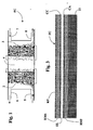
- Figure 1 is a schematic representation of the typical structure of a fuel cell which uses methanol in aqueous solution (CH 3 OH + H 2 O) as source of hydrogen.
- FC designates the cell as a whole, which comprises an anode 2 and a cathode 3, between which is set a suitable membrane 4, which has the function of electrolyte.
- the electrodes 2 and 3 can each be formed by applying on the opposite faces of the membrane 4 a thin catalytic layer, consisting of granules of carbon activated with noble metals and carrying PTFE or TeflonTM, for impermeabilization of some pores.
- a thin catalytic layer consisting of granules of carbon activated with noble metals and carrying PTFE or TeflonTM, for impermeabilization of some pores.
- the cell FC moreover envisages two bipolar plates that are located on both sides of the membrane 4 and are provided for enabling passage of electrical current and for yielding heat to the external environment.
- the reference numbers 5 and 6 designate, respectively, an inlet of the fuel in a chamber of the anode 2 and an outlet from said chamber for the carbon dioxide produced by the electrochemical reaction.
- the numbers 7 and 8 designate, respectively, an inlet for air into a chamber of the cathode 3 and an outlet from said chamber for the water produced by the electrochemical reaction.
- the alcohol laps the anode 2, whilst the oxidant laps the cathode 3.
- the catalytic layer of the anode 2 stimulates the electro-oxidation of the molecules of alcohol, which separate into positive ions and electrons. Whilst the electrons pass from the anode 2 to the cathode 3 through the electrical load, the protons migrate from the anode 2 to the cathode 3 through the membrane 4 and, once they have reached the cathode 3, combine with the oxygen in the air and with the electrons that come from the anode 2, to form water.
- the water-methanol mixture is sent directly to the anode 2, by means of the inlet 5, where it reacts, releasing CO 2 , H + ions, and electrons.
- the air is, instead, carried to the cathode 3, the O 2 of which reacts with the H + ions diffused through the membrane 4 and with the electrons, to be reduced to H 2 O.
- the cell reactions at the anode 2 and at the cathode 3 are, respectively, the following: CH 3 OH + H 2 O ⁇ 6e- + 6H + + CO 2 3/2O 2 + 6e - + 6H + ⁇ 3H 2 O which, combined, yield the overall reaction: CH 3 OH + 3/2O 2 ⁇ 2H 2 O + CO 2
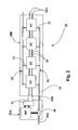
- Figure 2 is a schematic representation of a miniaturized direct-alcohol fuel-cell stack according to the invention, designated as a whole by 20.
- the fuel-cell stack 20 has a control portion 20A and a portion for generation of energy 20B.
- the portion 20B comprises a flexible support designated by 21, which in the case exemplified is in the form of a film made of polymeric material.
- a material usable for the fabrication of the supporting film 21 is Kapton ® , a light, insulating, polyamide material, which presents excellent resistance to heat, good thermal conductivity and is non-absorbent.
- FC miniaturized direct-methanol fuel cells
- the reference number 24 designates a duct for supply of the methanol-based fuel, from which there branch off the inlets 22.
- the number 25 designates a duct for discharge of the water generated by the cells FC, from which there branch off the outlets 23.
- the fuel-distribution system, formed by the duct 24 and by the inlets 22, and the water-discharge system, formed by the duct 25 and by the inlets 23, can be obtained by hot-pressing of a polymeric layer on the supporting film 21.
- the reference number 26 designates conducting paths that connect the cells FC in series to one another; said connections can be obtained by means of deposition of electrically conductive material on the supporting film 21.
- the control module 20A comprises a micro-pump 30, preferably of a piezoelectric type and made using MEMS (Micro Electro-Mechanical Systems) technology, which has the function of regulating the supply of fuel to the various cells FC.
- the micro-pump 30 comprises a respective inlet branch 30A, for connection to the source of methanol in aqueous solution, and a delivery branch 30B, provided for being hydraulically connected, with modalities in themselves known, to the duct 24 of the portion 20B.
- the micro-pump 30 has also the important function of maintaining the cell FC moist, when this is not in use, with the aim of preventing the deterioration of its electrode-electrolyte structure.
- the micro-pump 30 is controlled by a microprocessor designated by MP, which likewise controls a supercapacitor, designated by 31.
- the supercapacitor 31 is of a conception in itself known and consequently will not be described herein; here it will suffice to recall that a supercapacitor is an electronic device, obtainable using nanotechnologies, which is capable of accumulating static electricity and supplying electrical energy and is made up of two polarizable electrodes, a separator, and an electrolyte, where the electric field is stored in the interfaces between the electrolyte and the electrodes.
- the supercapacitor 31 is provided for being electrically connected, with modalities in themselves known, to the paths 26 at input to the first cell FC of the portion 20B. Its function is that of compensating the time of response of the electrochemical system and activating the electrical load supplied by the fuel-cell stack 20 before this can achieve the maximum electrical output to the output 26A of the paths 26.
- the first cell FC of the portion 20B of the fuel-cell stack functions then as charger of the supercapacitor 31, when the electrical load does not absorb current.
- a further function of the supercapacitor 31 is that of supplying the microprocessor MP, and thus also the micro-pump 30.
- FIG. 3 shows the multi-layer structure of an individual miniaturized cell FC provided according to the invention, which can be obtained with various procedures.
- the flexible supporting film 21 there are defined the paths 26, by means of deposition of electrically conductive material.
- the supporting film 21 is then provided with the fuel-distribution system 22, 24 and the water-discharge system 23, 25, for example by means of hot-pressing of a polymeric layer on the film itself.
- an electrode-electrolyte assembled structure which comprises:
- the electrode-electrolyte structure could be obtained by depositing the anodic catalyst CA on the layer RMI.
- the electrolyte EL On the anodic catalyst CA there will then be positioned or deposited the electrolyte EL. This will be followed, in order, by deposition of the cathodic catalyst CA, of the layer of metallic coating RMS, and of the possible protective layer RP.
- Another possibility is that of obtaining separately the complex formed by the layers RMI, CA, EL, CC, RMS, then to proceed to its fixing (for example, by gluing) on the flexible supporting film 21.
- the electrodes or catalysts CA, CC may comprise granules of carbon and a noble metal, such as for example platinum, palladium, rhodium, iridium, osmium or ruthenium, and the electrolyte EL can be in the form of a membrane of Nafion.
- a noble metal such as for example platinum, palladium, rhodium, iridium, osmium or ruthenium
- the electrolyte EL can be in the form of a membrane of Nafion.
- the electrolyte EL may thus advantageously be in the form of a composite Nafion-zeolite membrane, in order to enable reduction of the crossover of methanol.
- the catalysts CA, CC can comprise fullerenes and/or carbon nanotubes and/or carbon nanofibres.
- the said structure is thus configured as a continuous ribbon having a thickness of some millimetres, which can be rolled up. From said ribbon it will be possible to cut a piece designed to form the portion 20B illustrated in Figure 2 , comprising a desired number of cells FC according to the total voltage that it is intended to reach. To this piece there will evidently be combined the respective control portion 20A.
- micromachining for obtaining multiple layers that form the components of the cells FC on the flexible substrate made from the film 21 enables, according to the invention, production of low-cost fuel-cell stacks with high production volumes.
Landscapes
- Chemical & Material Sciences (AREA)
- General Chemical & Material Sciences (AREA)
- Electrochemistry (AREA)
- Chemical Kinetics & Catalysis (AREA)
- Sustainable Energy (AREA)
- Life Sciences & Earth Sciences (AREA)
- Sustainable Development (AREA)
- Manufacturing & Machinery (AREA)
- Engineering & Computer Science (AREA)
- Crystallography & Structural Chemistry (AREA)
- Composite Materials (AREA)
- Fuel Cell (AREA)
- Inert Electrodes (AREA)
- Confectionery (AREA)
- Investigating Or Analysing Materials By Optical Means (AREA)
- Fats And Perfumes (AREA)
Abstract
Description
- The present invention relates to a direct-alcohol fuel-cell stack.
- Fuel cells are electrochemical devices capable of converting the chemical energy contained in a fuel into electrical direct current, in the absence of moving parts.
- Said electrochemical device comprises an anode and a cathode separated by an electrolyte, i.e., a substance that enables migration of the ions. In order to favour the electrochemical reactions it is necessary to use appropriate catalysts, for example platinum.
- The cell is supplied with the fuel (typically hydrogen or another molecule containing hydrogen) and with an oxidant (typically oxygen or air), which, electrochemically combined, generate electricity and produce water as waste product.
- The individual cells, characterized by voltages comprised between half a volt and one volt according to the technology adopted, can be connected in series, so as to obtain a total voltage of the desired value. Said arrangement of the cells forms the so-called fuel-cell stack, to which there can be associated an inverter and a transformer for converting the direct current generated by the stack of cells into alternating current at the desired voltage and at the desired frequency.
- Development of fuel cells and of their applications is currently retarded to a large extent by the production costs involved, which are still high, and by certain technological and manufacturing problems.
- In this perspective, it should for example be noted that the traditional systems of production of electrode structures for fuel cells are based upon the deposition of catalysts on carbon substrates, hot-pressed on an electrolyte in the form of a membrane. The said technique has proven costly.
- Current fuel cells suffer, moreover, from a certain slowness of operation in the step of start-up of the electrochemical process, and this precludes their use in those applications that entail an immediate generation of electrical energy.
- From
DE-A-196 24 887 , upon which the preamble ofclaim 1 and 22 is based, an electrochemical solid electrolyte cell system is known, based on a flat, gas-permeable, non-conductive flexible polymer substrate. The cell regions consist of a porous, electrically-conductive, flexible electrode layer, a proton conducting, flexible membrane layer and a second porous, flexible, electron-conducting electrode layer, the various layers being laid one over the other, using coating technologies. - The purpose of the present invention is to provide a newly conceived fuel cell stack, of particularly advantageous use from the cost point of view and/or from the functional point of view for the purposes of production of fuel-cell stack usable as independent systems for the production of energy.
- This and other purposes are achieved, according to the present invention, by a fuel-cell stack having the feature of claim 1, as well as by a method for the fabrication of a fuel-cell stack having the feature of
claim 22. - Preferred embodiments of the fuel-cell according to the invention and of its method of fabrication are specified in the dependent claims.
- Further purposes, characteristics and advantages of the present invention will emerge clearly from the description that follows with reference to the annexed drawings, which are provided purely by way of nonlimiting example and in which:
-
Figure 1 is a schematic illustration of the structure of a direct-methanol fuel cell; -
Figure 2 is a schematic illustration of a miniaturized fuel-cell obtained in accordance with the present invention; and -
Figure 3 represents a schematic cross-sectional view of a miniaturized fuel cell obtained according to the invention. - As mentioned in the introductory part of the present description, a fuel cell is a system consisting of two electrodes (an anode and a cathode), between which is set an electrolyte, usually in the form of a membrane, which directly converts chemical energy into electrical energy, without combustion or moving parts, by means of the electrochemical combination of hydrogen and oxygen, producing water, electricity and heat.
- Methanol has proven one of the best candidates as fuel for fuel cells, on account of its ease of storage and transportation and its low cost. The use of methanol in liquid form enables a considerable reduction of the complexity of the fuel cells, enabling their application in various sectors. It should moreover be noted that in the case of cells which use methanol in aqueous solution, known as direct-methanol fuel cells (DMFCs), the fuel can be supplied in the absence of preliminary reforming, i.e., a treatment to which fuels rich in hydrocarbons must, instead, be subjected for converting them into hydrogen.
-
Figure 1 is a schematic representation of the typical structure of a fuel cell which uses methanol in aqueous solution (CH3OH + H2O) as source of hydrogen. - In said figure, FC designates the cell as a whole, which comprises an
anode 2 and acathode 3, between which is set a suitable membrane 4, which has the function of electrolyte. - The
electrodes - The cell FC moreover envisages two bipolar plates that are located on both sides of the membrane 4 and are provided for enabling passage of electrical current and for yielding heat to the external environment.
- The
reference numbers anode 2 and an outlet from said chamber for the carbon dioxide produced by the electrochemical reaction. Thenumbers 7 and 8 designate, respectively, an inlet for air into a chamber of thecathode 3 and an outlet from said chamber for the water produced by the electrochemical reaction. - In a cell of the type illustrated in
Figure 1 , the alcohol laps theanode 2, whilst the oxidant laps thecathode 3. The catalytic layer of theanode 2 stimulates the electro-oxidation of the molecules of alcohol, which separate into positive ions and electrons. Whilst the electrons pass from theanode 2 to thecathode 3 through the electrical load, the protons migrate from theanode 2 to thecathode 3 through the membrane 4 and, once they have reached thecathode 3, combine with the oxygen in the air and with the electrons that come from theanode 2, to form water. - In other words, then, the water-methanol mixture is sent directly to the
anode 2, by means of theinlet 5, where it reacts, releasing CO2, H+ ions, and electrons. - By means of the inlet 7, the air is, instead, carried to the
cathode 3, the O2 of which reacts with the H+ ions diffused through the membrane 4 and with the electrons, to be reduced to H2O. - The cell reactions at the
anode 2 and at thecathode 3 are, respectively, the following:
CH3OH + H2O → 6e- + 6H+ + CO2 3/2O2 + 6e- + 6H+ → 3H2O
which, combined, yield the overall reaction:
CH3OH + 3/2O2 → 2H2O + CO2
- There may thus be noted the transport of three different species:
- the electrons move through the carbon of the electrode/catalyst;
- the gases diffuse through the impermeabilized pores of the electrode layer, which, as has been said, consists of granules of carbon activated with noble metals and carrying PTFE or Teflon™ for impermeabilization of some pores;
- the liquid water flows through the non-impermeabilized pores.
- According to a first important aspect of the invention, it is proposed to provide a new miniaturized structure of fuel cell of the type mentioned above, made up of more than one layers of different materials on a flexible support.
-
Figure 2 is a schematic representation of a miniaturized direct-alcohol fuel-cell stack according to the invention, designated as a whole by 20. - The fuel-
cell stack 20 has acontrol portion 20A and a portion for generation ofenergy 20B. Theportion 20B comprises a flexible support designated by 21, which in the case exemplified is in the form of a film made of polymeric material. By way of example, a material usable for the fabrication of the supportingfilm 21 is Kapton® , a light, insulating, polyamide material, which presents excellent resistance to heat, good thermal conductivity and is non-absorbent. - Provided on the
film 21 are a plurality of miniaturized direct-methanol fuel cells, designated by FC, each provided with aninlet 22 for the fuel and anoutlet 23 for the water resulting from the chemical reaction. - The
reference number 24 designates a duct for supply of the methanol-based fuel, from which there branch off theinlets 22. Thenumber 25 designates a duct for discharge of the water generated by the cells FC, from which there branch off theoutlets 23. - The fuel-distribution system, formed by the
duct 24 and by theinlets 22, and the water-discharge system, formed by theduct 25 and by theinlets 23, can be obtained by hot-pressing of a polymeric layer on the supportingfilm 21. - The
reference number 26 designates conducting paths that connect the cells FC in series to one another; said connections can be obtained by means of deposition of electrically conductive material on the supportingfilm 21. - The
control module 20A comprises a micro-pump 30, preferably of a piezoelectric type and made using MEMS (Micro Electro-Mechanical Systems) technology, which has the function of regulating the supply of fuel to the various cells FC. For this purpose, the micro-pump 30 comprises arespective inlet branch 30A, for connection to the source of methanol in aqueous solution, and adelivery branch 30B, provided for being hydraulically connected, with modalities in themselves known, to theduct 24 of theportion 20B. - The micro-pump 30 has also the important function of maintaining the cell FC moist, when this is not in use, with the aim of preventing the deterioration of its electrode-electrolyte structure.
- The micro-pump 30 is controlled by a microprocessor designated by MP, which likewise controls a supercapacitor, designated by 31. The
supercapacitor 31 is of a conception in itself known and consequently will not be described herein; here it will suffice to recall that a supercapacitor is an electronic device, obtainable using nanotechnologies, which is capable of accumulating static electricity and supplying electrical energy and is made up of two polarizable electrodes, a separator, and an electrolyte, where the electric field is stored in the interfaces between the electrolyte and the electrodes. - In the application herein proposed, the
supercapacitor 31 is provided for being electrically connected, with modalities in themselves known, to thepaths 26 at input to the first cell FC of theportion 20B. Its function is that of compensating the time of response of the electrochemical system and activating the electrical load supplied by the fuel-cell stack 20 before this can achieve the maximum electrical output to theoutput 26A of thepaths 26. The first cell FC of theportion 20B of the fuel-cell stack, as in a loop, functions then as charger of thesupercapacitor 31, when the electrical load does not absorb current. - A further function of the
supercapacitor 31 is that of supplying the microprocessor MP, and thus also themicro-pump 30. - As mentioned previously, traditional systems of production of the electrode structures for fuel cells are based upon the deposition of catalysts on carbon substrates, hot-pressed on the electrolyte, i.e., the membrane.
- According to the present invention, there is instead proposed recourse to micromachining to obtain multiple layers that form the components of the cells FC on the substrate made from the
film 21, with a technique similar to the one currently in use for the production of various printed circuits. -
Figure 3 shows the multi-layer structure of an individual miniaturized cell FC provided according to the invention, which can be obtained with various procedures. - In a first possible implementation, on the flexible supporting
film 21 there are defined thepaths 26, by means of deposition of electrically conductive material. The supportingfilm 21 is then provided with the fuel-distribution system discharge system - Subsequently, in an area corresponding to the area in which a cell FC is to be obtained, deposited on the
film 21 is a layer of metallic coating, designated inFigure 3 by RMI. On the layer RMI there is then positioned an electrode-electrolyte assembled structure, which comprises: - an appropriate anodic catalyst, designated by CA, which functions as positive electrode;
- an appropriate cathodic catalyst, designated by CC, which functions as negative electrode; and
- a suitable electrolyte EL, set between the anodic catalyst CA and the cathodic catalyst CC.
- Following upon positioning of the aforesaid assembled structure, on the cathodic catalyst, there is deposited a layer of metallic coating RMS. Possibly deposited on the latter is, finally, a protective layer made of polymeric material RP.
- As an alternative to the technique described herein, the electrode-electrolyte structure could be obtained by depositing the anodic catalyst CA on the layer RMI.
- On the anodic catalyst CA there will then be positioned or deposited the electrolyte EL. This will be followed, in order, by deposition of the cathodic catalyst CA, of the layer of metallic coating RMS, and of the possible protective layer RP.
- Another possibility is that of obtaining separately the complex formed by the layers RMI, CA, EL, CC, RMS, then to proceed to its fixing (for example, by gluing) on the flexible supporting
film 21. - Operation of the miniaturized cells FC forming part of the fuel-cell stack illustrated in
Figure 2 is similar to the one described previously with reference toFigure 1 . It is to be noted, in this connection, that the metallic layers RMI and RMS provide means for conducting the electrical current to the electrodes CA, CC. - The electrodes or catalysts CA, CC may comprise granules of carbon and a noble metal, such as for example platinum, palladium, rhodium, iridium, osmium or ruthenium, and the electrolyte EL can be in the form of a membrane of Nafion.
- In a preferred embodiment, it is possible to envisage deposition of the catalysts CA, CC on zeolite materials, with the aim of increasing the catalytic activity. The electrolyte EL may thus advantageously be in the form of a composite Nafion-zeolite membrane, in order to enable reduction of the crossover of methanol.
- Once again in order to increase the catalytic activity, in an advantageous variant embodiment, the catalysts CA, CC can comprise fullerenes and/or carbon nanotubes and/or carbon nanofibres.
- From what has been described previously, it is clear how the cells FC are supported by a
polymeric film 21, giving rise to an overall flexible structure that may present a considerable development in length. - In effect, the said structure is thus configured as a continuous ribbon having a thickness of some millimetres, which can be rolled up. From said ribbon it will be possible to cut a piece designed to form the
portion 20B illustrated inFigure 2 , comprising a desired number of cells FC according to the total voltage that it is intended to reach. To this piece there will evidently be combined therespective control portion 20A. - The use of micromachining for obtaining multiple layers that form the components of the cells FC on the flexible substrate made from the
film 21 enables, according to the invention, production of low-cost fuel-cell stacks with high production volumes. - Of course, without prejudice to the principle of the invention, the details of construction and the embodiments may vary with respect to what is described and illustrated herein purely by way of example.
- It is to be pointed out, in particular, that the structure described is applicable also to the production of other types of direct-alcohol fuel cells, i.e., designed for being supplied with ethanol or other alcohols different from methanol.
Claims (26)
- A fuel-cell stack (20), comprising a plurality of direct-alcohol fuel cells (FC), each cell (FC) having a structure comprising:- a first electrode (CA);- a second electrode (CC);- an electrolyte (EL) arranged between the first electrode (CA) and the second electrode (CC);- means (RMI, RMS) for conducting electrical current to the first electrode (CA) and the second electrode (CC),wherein- said structure is miniaturized and made up of a plurality of layers set on top of one another, and- the structures of the cells of said plurality are associated in an irremovable way to a same flexible substrate (21),characterized in that further associated in an irremovable way to said flexible substrate (21) there are:- a fuel inlet (22) for each cell (FC) of the stack, the fuel inlets (22) branching off from a first duct (24) for the fuel, the first duct (24) being also associated in an irremovable way to said flexible substrate (21), and- a water outlet (23) for each cell (FC) of the stack, the water outlets (23) branching off from a second duct (25) for water produced by the cell chemical reaction, the second duct (25) being also associated in an irremovable way to said flexible substrate (21) .
- The fuel-cell stack according to Claim 1, characterized in that said first duct (22) with said fuel inlets (22) and said second duct (25) with said water outlet (23) are formed by a polymeric layer hot-pressed on said flexible substrate (21).
- The fuel-cell stack according to Claim 1, characterized in that said flexible substrate (21) is made of polymeric material, in particular Kapton® .
- The fuel-cell stack according to Claim 1, characterized in that associated in an irremovable way to the flexible substrate (21) there are also conducting paths (26), which electrically connect in series the cells of said plurality.
- The fuel-cell stack according to Claim 1, characterized in that said means for conducting electrical current (RMI, RMS) comprise:- a first layer of metallic material (RMI) resting on said flexible substrate (21), said first electrode comprising an anodic catalyst (CA) in contact with said first layer (RMI), and- a second layer of metallic material (RMS) resting on the electrolyte (EL), the second electrode comprising a cathodic catalyst (CC) in contact with said second layer (RMS).
- The fuel-cell stack according to Claim 5, characterized in that on said second layer (RMS) there is present a protective layer (RP), in particular made of polymeric material.
- The fuel-cell stack according to Claim 1, characterized in that the electrolyte (EL) is in the form of a membrane, in particular made of Nafion.
- The fuel-cell stack according to Claim 1, characterized in that the electrolyte (EL) has a composite structure comprising Nafion and zeolite.
- The fuel-cell stack according to Claim 1, characterized in that said means for conducting electrical current to the first electrode and the second electrode are in the form of metallic layers (RMI, RMS).
- The fuel-cell stack according to Claim 1, characterized in that at least one of the first electrode and the second electrode comprises a catalyst (CA, CC) containing granules of carbon and a noble metal selected in the group consisting of platinum, palladium, rhodium, iridium, osmium and ruthenium.
- The fuel-cell stack according to Claim 1, characterized in that at least one of the first electrode and the second electrode comprises a catalyst (CA, CC) containing a material selected in the group consisting of fullerenes, carbon nanotubes, carbon nanofibres.
- The fuel-cell stack according to Claim 1, characterized in that at least one of the first electrode and the second electrode comprises a catalyst (CA, CC) deposited on zeolite material.
- The fuel-cell stack according to Claim 1, characterized in that it comprises a first control part (20A) and a second energy-generation part (20B), the first part having a micro-pump (30), which is operative for regulating the supply of the fuel to the cells (FC), the micro-pump (30) comprising:- a respective inlet branch (30A), for connection to a source of the fuel; and- a delivery branch (30B), for connection to said first conduit (24).
- The fuel-cell stack according to Claim 13, characterized in that said micro-pump is a piezoelectric pump made using MEMS (Micro Electro-Mechanical Systems) technology.
- The fuel-cell stack according to Claim 13, characterized in that said micro-pump (30) is operative for maintaining the cells (FC) of said plurality moist, in order to prevent deterioration of the miniaturized structure thereof.
- The fuel-cell stack according to Claim 13, characterized in that said first part (20A) comprises a microcontroller (MP) for the control of the micro-pump (30).
- The fuel-cell stack according to Claim 13, characterized in that said first part (20A) comprises a supercapacitor (31) provided for the electrical connection to a cell (FC) of said plurality.
- The fuel-cell stack according to Claims 16 and 17, characterized in that said supercapacitor is operative for supplying said microcontroller (MP).
- The fuel-cell stack according to Claim 13, characterized in that said second part (20B) comprises said flexible substrate (21) with the respective plurality of cells (FC) and portions of the first and the second ducts (24, 25) and in that said first part (20A) is distinct from the flexible substrate (21) and provided for being connected electrically to a cell (FC) of said second part (20B) and hydraulically to the first conduit (24) of the second part (20B).
- The fuel-cell stack according to Claim 1, characterized in that said flexible substrate (21) is in the form of a ribbon developing in length and adapted to be rolled up.
- The fuel-cell stack according to Claim 1, characterized in that the cells (FC) are designed to be fed with methanol in aqueous solution.
- A method for the fabrication of a fuel-cell stack (20) comprising a plurality of direct-alcohol fuel cells according to one or more of claims 1 to 21, comprising the steps of:i) obtaining a flexible substrate (21) in the form of a ribbon that develops in length;ii) associating to the flexible substrate (21), in an irremovable way, a plurality of said miniaturized structures made up of a plurality of layers set on top of one another, said layers being obtained by means of micromachining;
characterized by also comprising the steps of:iii) associating in an irremovable way to said flexible substrate (21):- a fuel inlet (22) for each cell (FC) of the stack, the fuel inlets (22) branching off from a first duct (24) for the fuel, the first duct (24) being also associated in an irremovable way to said flexible substrate (21), and- a water outlet (23) for each cell (FC) of the stack, the water outlets (23) branching off from a second duct (25) for water produced by the cell chemical reaction, the second duct (25) being also associated in an irremovable way to said flexible substrate (21),iv) cutting the flexible substrate (21) in order to obtain a piece (20B) comprising a desired number of said cells (FC) and including a respective portion of said first and second conduits (24, 25),v) electrically connecting a cell (FC) of said piece (20B) and hydraulically connecting said first duct (24) to a control device (20A), the ensemble of said piece (20B) and said control device (20A) forming the fuel-cell stack (20). - The method according to Claim 22,
characterized in that step iii) comprises hot-pressing a polymeric layer on said flexible substrate (21). - The method according to Claim 22,
characterized in that step ii) includes associating to the flexible substrate (21) conducting paths (26) that electrically connect in series the cells of said piece (20B) . - The method according to Claim 23,
characterized in that step v) comprises hydraulically connecting a pump (30) forming part of said control device (20A) to said first conduit (24). - The method according to Claim 24,
characterized in that step v) comprises electrically connecting a supercapacitor (31) forming part of said control device (20A) to the conducting paths (26) of a cell (FC) of said piece (20B) .
Applications Claiming Priority (2)
| Application Number | Priority Date | Filing Date | Title |
|---|---|---|---|
| IT2002TO000643A ITTO20020643A1 (en) | 2002-07-23 | 2002-07-23 | DIRECT ALCOHOL FUEL BATTERY AND RELATED METHOD OF REALIZATION |
| ITTO20020643 | 2002-07-23 |
Publications (3)
| Publication Number | Publication Date |
|---|---|
| EP1385225A2 EP1385225A2 (en) | 2004-01-28 |
| EP1385225A3 EP1385225A3 (en) | 2006-02-01 |
| EP1385225B1 true EP1385225B1 (en) | 2008-05-21 |
Family
ID=11459519
Family Applications (1)
| Application Number | Title | Priority Date | Filing Date |
|---|---|---|---|
| EP03013025A Expired - Lifetime EP1385225B1 (en) | 2002-07-23 | 2003-06-10 | A direct-alcohol fuel-cell and corresponding method of fabrication |
Country Status (6)
| Country | Link |
|---|---|
| US (1) | US7442460B2 (en) |
| EP (1) | EP1385225B1 (en) |
| JP (1) | JP2004055550A (en) |
| AT (1) | ATE396511T1 (en) |
| DE (1) | DE60321094D1 (en) |
| IT (1) | ITTO20020643A1 (en) |
Families Citing this family (12)
| Publication number | Priority date | Publication date | Assignee | Title |
|---|---|---|---|---|
| US6723299B1 (en) | 2001-05-17 | 2004-04-20 | Zyvex Corporation | System and method for manipulating nanotubes |
| US6905667B1 (en) | 2002-05-02 | 2005-06-14 | Zyvex Corporation | Polymer and method for using the polymer for noncovalently functionalizing nanotubes |
| US20040034177A1 (en) | 2002-05-02 | 2004-02-19 | Jian Chen | Polymer and method for using the polymer for solubilizing nanotubes |
| KR100827861B1 (en) * | 2003-05-22 | 2008-05-07 | 지벡스 퍼포먼스 머티리얼즈, 엘엘씨 | Nanocomposites and methods thereto |
| JP5254608B2 (en) * | 2004-04-13 | 2013-08-07 | ザイベックス パフォーマンス マテリアルズ、インク. | Method for synthesizing modular poly (phenylene ethylenin) and method for fine-tuning its electronic properties to functionalize nanomaterials |
| US7296576B2 (en) * | 2004-08-18 | 2007-11-20 | Zyvex Performance Materials, Llc | Polymers for enhanced solubility of nanomaterials, compositions and methods therefor |
| JP4765307B2 (en) * | 2004-12-10 | 2011-09-07 | パナソニック株式会社 | Fuel cell system |
| DE102005015660B4 (en) * | 2005-04-06 | 2013-03-28 | Forschungszentrum Jülich GmbH | Low-temperature fuel cell stack and method for operating the same |
| US8033501B2 (en) * | 2005-06-10 | 2011-10-11 | The Boeing Company | Method and apparatus for attaching electrically powered seat track cover to through hole seat track design |
| US20090263698A1 (en) * | 2005-10-20 | 2009-10-22 | Nec Corporation | Fuel cell system and fuel cell |
| US9227895B2 (en) * | 2007-07-09 | 2016-01-05 | Albemarle Corporation | Methods and apparatus for producing alcohols from syngas |
| EP2173694B1 (en) * | 2007-07-09 | 2016-11-23 | Albemarle Corporation | Methods for producing alcohols from syngas |
Family Cites Families (8)
| Publication number | Priority date | Publication date | Assignee | Title |
|---|---|---|---|---|
| WO1997001194A1 (en) * | 1995-06-21 | 1997-01-09 | Fraunhofer-Gesellschaft zur Förderung der angewandten Forschung e.V. | Electrochemical solid electrolyte cell system |
| US6299744B1 (en) * | 1997-09-10 | 2001-10-09 | California Institute Of Technology | Hydrogen generation by electrolysis of aqueous organic solutions |
| CA2370899A1 (en) * | 1999-05-06 | 2000-11-16 | Sandia Corporation | Fuel cell and membrane |
| US6503654B2 (en) * | 1999-05-19 | 2003-01-07 | George A. Marchetti | Thin graphite bipolar plate with associated gaskets and carbon cloth flow-field for use in an ionomer membrane fuel cell |
| TW434927B (en) * | 1999-11-03 | 2001-05-16 | Ind Tech Res Inst | Method for fabricating metal-air battery and its structure |
| US6541149B1 (en) * | 2000-02-29 | 2003-04-01 | Lucent Technologies Inc. | Article comprising micro fuel cell |
| WO2002013295A1 (en) * | 2000-08-08 | 2002-02-14 | Sony Corporation | Proton-conductive electrode, process for producing the same, and electrochemical device |
| US6620542B2 (en) * | 2001-05-30 | 2003-09-16 | Hewlett-Packard Development Company, L.P. | Flex based fuel cell |
-
2002
- 2002-07-23 IT IT2002TO000643A patent/ITTO20020643A1/en unknown
-
2003
- 2003-06-10 EP EP03013025A patent/EP1385225B1/en not_active Expired - Lifetime
- 2003-06-10 AT AT03013025T patent/ATE396511T1/en not_active IP Right Cessation
- 2003-06-10 DE DE60321094T patent/DE60321094D1/en not_active Expired - Lifetime
- 2003-07-02 JP JP2003190386A patent/JP2004055550A/en active Pending
- 2003-07-23 US US10/624,608 patent/US7442460B2/en not_active Expired - Fee Related
Also Published As
| Publication number | Publication date |
|---|---|
| US20040018423A1 (en) | 2004-01-29 |
| ATE396511T1 (en) | 2008-06-15 |
| EP1385225A3 (en) | 2006-02-01 |
| JP2004055550A (en) | 2004-02-19 |
| ITTO20020643A0 (en) | 2002-07-23 |
| EP1385225A2 (en) | 2004-01-28 |
| ITTO20020643A1 (en) | 2004-01-23 |
| DE60321094D1 (en) | 2008-07-03 |
| US7442460B2 (en) | 2008-10-28 |
Similar Documents
| Publication | Publication Date | Title |
|---|---|---|
| US7807317B2 (en) | Anode electrodes for direct oxidation fuel cells and systems operating with concentrated liquid fuel | |
| EP1366533B1 (en) | Fuel cell array | |
| US20020076598A1 (en) | Direct methanol fuel cell including integrated flow field and method of fabrication | |
| US20030157396A1 (en) | Modified diffusion layer for use in a fuel cell system | |
| NL1021701C2 (en) | PEM fuel cell. | |
| KR20030076559A (en) | Direct methanol fuel cell system | |
| EP1385225B1 (en) | A direct-alcohol fuel-cell and corresponding method of fabrication | |
| WO2005082024A2 (en) | Fuel cell apparatus and method of fabrication | |
| US6794071B2 (en) | Apparatus and method for rapidly increasing power output from a direct oxidation fuel cell | |
| KR20110094082A (en) | Fuel cell | |
| EP2287955A2 (en) | Method for manufacturing a polymer electrolyte membrane for fuel cell, membrane electrode assembly, and polymer electrolyte membrane type fuel cell | |
| US20100068592A1 (en) | Electrodes for use in hydrocarbon-based membrane electrode assemblies of direct oxidation fuel cells | |
| CN118202085A (en) | Device and method for producing hydrogen peroxide | |
| US8227137B2 (en) | Polymer membrane for fuel cell and method of preparing the same | |
| US8133633B2 (en) | Structure of cathode electrode for fuel cell | |
| US20050164059A1 (en) | Local vapor fuel cell | |
| CN100334767C (en) | liquid fuel supply type fuel cell | |
| WO2009119434A1 (en) | Fuel cell unit, fuel cell stack and electronic device | |
| JP2005141994A (en) | Polymer electrolyte fuel cell | |
| US20070003801A1 (en) | Fuel cell | |
| JP3946228B2 (en) | Fuel cell | |
| KR20250082014A (en) | Unitized regenerative fuel cell and stacks using the same | |
| CN121079805A (en) | Fuel cell | |
| KR20110124947A (en) | Flexible fuel cell | |
| KR20050122452A (en) | Bipolar plate for fuel cell, method of preparing same and fuel cell comprising same |
Legal Events
| Date | Code | Title | Description |
|---|---|---|---|
| PUAI | Public reference made under article 153(3) epc to a published international application that has entered the european phase |
Free format text: ORIGINAL CODE: 0009012 |
|
| AK | Designated contracting states |
Kind code of ref document: A2 Designated state(s): AT BE BG CH CY CZ DE DK EE ES FI FR GB GR HU IE IT LI LU MC NL PT RO SE SI SK TR |
|
| AX | Request for extension of the european patent |
Extension state: AL LT LV MK |
|
| PUAL | Search report despatched |
Free format text: ORIGINAL CODE: 0009013 |
|
| AK | Designated contracting states |
Kind code of ref document: A3 Designated state(s): AT BE BG CH CY CZ DE DK EE ES FI FR GB GR HU IE IT LI LU MC NL PT RO SE SI SK TR |
|
| AX | Request for extension of the european patent |
Extension state: AL LT LV MK |
|
| 17P | Request for examination filed |
Effective date: 20060403 |
|
| 17Q | First examination report despatched |
Effective date: 20060905 |
|
| AKX | Designation fees paid |
Designated state(s): AT BE BG CH CY CZ DE DK EE ES FI FR GB GR HU IE IT LI LU MC NL PT RO SE SI SK TR |
|
| GRAP | Despatch of communication of intention to grant a patent |
Free format text: ORIGINAL CODE: EPIDOSNIGR1 |
|
| GRAS | Grant fee paid |
Free format text: ORIGINAL CODE: EPIDOSNIGR3 |
|
| GRAA | (expected) grant |
Free format text: ORIGINAL CODE: 0009210 |
|
| AK | Designated contracting states |
Kind code of ref document: B1 Designated state(s): AT BE BG CH CY CZ DE DK EE ES FI FR GB GR HU IE IT LI LU MC NL PT RO SE SI SK TR |
|
| REG | Reference to a national code |
Ref country code: GB Ref legal event code: FG4D |
|
| REG | Reference to a national code |
Ref country code: CH Ref legal event code: EP |
|
| REF | Corresponds to: |
Ref document number: 60321094 Country of ref document: DE Date of ref document: 20080703 Kind code of ref document: P |
|
| REG | Reference to a national code |
Ref country code: IE Ref legal event code: FG4D |
|
| PG25 | Lapsed in a contracting state [announced via postgrant information from national office to epo] |
Ref country code: SI Free format text: LAPSE BECAUSE OF FAILURE TO SUBMIT A TRANSLATION OF THE DESCRIPTION OR TO PAY THE FEE WITHIN THE PRESCRIBED TIME-LIMIT Effective date: 20080521 |
|
| PG25 | Lapsed in a contracting state [announced via postgrant information from national office to epo] |
Ref country code: FI Free format text: LAPSE BECAUSE OF FAILURE TO SUBMIT A TRANSLATION OF THE DESCRIPTION OR TO PAY THE FEE WITHIN THE PRESCRIBED TIME-LIMIT Effective date: 20080521 Ref country code: ES Free format text: LAPSE BECAUSE OF FAILURE TO SUBMIT A TRANSLATION OF THE DESCRIPTION OR TO PAY THE FEE WITHIN THE PRESCRIBED TIME-LIMIT Effective date: 20080901 |
|
| NLV1 | Nl: lapsed or annulled due to failure to fulfill the requirements of art. 29p and 29m of the patents act | ||
| PG25 | Lapsed in a contracting state [announced via postgrant information from national office to epo] |
Ref country code: AT Free format text: LAPSE BECAUSE OF FAILURE TO SUBMIT A TRANSLATION OF THE DESCRIPTION OR TO PAY THE FEE WITHIN THE PRESCRIBED TIME-LIMIT Effective date: 20080521 Ref country code: NL Free format text: LAPSE BECAUSE OF FAILURE TO SUBMIT A TRANSLATION OF THE DESCRIPTION OR TO PAY THE FEE WITHIN THE PRESCRIBED TIME-LIMIT Effective date: 20080521 |
|
| PG25 | Lapsed in a contracting state [announced via postgrant information from national office to epo] |
Ref country code: CZ Free format text: LAPSE BECAUSE OF FAILURE TO SUBMIT A TRANSLATION OF THE DESCRIPTION OR TO PAY THE FEE WITHIN THE PRESCRIBED TIME-LIMIT Effective date: 20080521 Ref country code: MC Free format text: LAPSE BECAUSE OF NON-PAYMENT OF DUE FEES Effective date: 20080630 Ref country code: SE Free format text: LAPSE BECAUSE OF FAILURE TO SUBMIT A TRANSLATION OF THE DESCRIPTION OR TO PAY THE FEE WITHIN THE PRESCRIBED TIME-LIMIT Effective date: 20080821 Ref country code: DK Free format text: LAPSE BECAUSE OF FAILURE TO SUBMIT A TRANSLATION OF THE DESCRIPTION OR TO PAY THE FEE WITHIN THE PRESCRIBED TIME-LIMIT Effective date: 20080521 Ref country code: PT Free format text: LAPSE BECAUSE OF FAILURE TO SUBMIT A TRANSLATION OF THE DESCRIPTION OR TO PAY THE FEE WITHIN THE PRESCRIBED TIME-LIMIT Effective date: 20081021 |
|
| REG | Reference to a national code |
Ref country code: CH Ref legal event code: PL |
|
| PG25 | Lapsed in a contracting state [announced via postgrant information from national office to epo] |
Ref country code: RO Free format text: LAPSE BECAUSE OF FAILURE TO SUBMIT A TRANSLATION OF THE DESCRIPTION OR TO PAY THE FEE WITHIN THE PRESCRIBED TIME-LIMIT Effective date: 20080521 Ref country code: SK Free format text: LAPSE BECAUSE OF FAILURE TO SUBMIT A TRANSLATION OF THE DESCRIPTION OR TO PAY THE FEE WITHIN THE PRESCRIBED TIME-LIMIT Effective date: 20080521 Ref country code: BE Free format text: LAPSE BECAUSE OF FAILURE TO SUBMIT A TRANSLATION OF THE DESCRIPTION OR TO PAY THE FEE WITHIN THE PRESCRIBED TIME-LIMIT Effective date: 20080521 |
|
| PLBE | No opposition filed within time limit |
Free format text: ORIGINAL CODE: 0009261 |
|
| STAA | Information on the status of an ep patent application or granted ep patent |
Free format text: STATUS: NO OPPOSITION FILED WITHIN TIME LIMIT |
|
| 26N | No opposition filed |
Effective date: 20090224 |
|
| GBPC | Gb: european patent ceased through non-payment of renewal fee |
Effective date: 20080821 |
|
| PG25 | Lapsed in a contracting state [announced via postgrant information from national office to epo] |
Ref country code: BG Free format text: LAPSE BECAUSE OF FAILURE TO SUBMIT A TRANSLATION OF THE DESCRIPTION OR TO PAY THE FEE WITHIN THE PRESCRIBED TIME-LIMIT Effective date: 20080821 Ref country code: IE Free format text: LAPSE BECAUSE OF NON-PAYMENT OF DUE FEES Effective date: 20080610 Ref country code: EE Free format text: LAPSE BECAUSE OF FAILURE TO SUBMIT A TRANSLATION OF THE DESCRIPTION OR TO PAY THE FEE WITHIN THE PRESCRIBED TIME-LIMIT Effective date: 20080521 |
|
| PG25 | Lapsed in a contracting state [announced via postgrant information from national office to epo] |
Ref country code: LI Free format text: LAPSE BECAUSE OF NON-PAYMENT OF DUE FEES Effective date: 20080630 Ref country code: CH Free format text: LAPSE BECAUSE OF NON-PAYMENT OF DUE FEES Effective date: 20080630 |
|
| PG25 | Lapsed in a contracting state [announced via postgrant information from national office to epo] |
Ref country code: GB Free format text: LAPSE BECAUSE OF NON-PAYMENT OF DUE FEES Effective date: 20080821 |
|
| PG25 | Lapsed in a contracting state [announced via postgrant information from national office to epo] |
Ref country code: HU Free format text: LAPSE BECAUSE OF FAILURE TO SUBMIT A TRANSLATION OF THE DESCRIPTION OR TO PAY THE FEE WITHIN THE PRESCRIBED TIME-LIMIT Effective date: 20081122 Ref country code: CY Free format text: LAPSE BECAUSE OF FAILURE TO SUBMIT A TRANSLATION OF THE DESCRIPTION OR TO PAY THE FEE WITHIN THE PRESCRIBED TIME-LIMIT Effective date: 20080521 Ref country code: LU Free format text: LAPSE BECAUSE OF NON-PAYMENT OF DUE FEES Effective date: 20080610 |
|
| PG25 | Lapsed in a contracting state [announced via postgrant information from national office to epo] |
Ref country code: TR Free format text: LAPSE BECAUSE OF FAILURE TO SUBMIT A TRANSLATION OF THE DESCRIPTION OR TO PAY THE FEE WITHIN THE PRESCRIBED TIME-LIMIT Effective date: 20080521 |
|
| PG25 | Lapsed in a contracting state [announced via postgrant information from national office to epo] |
Ref country code: GR Free format text: LAPSE BECAUSE OF FAILURE TO SUBMIT A TRANSLATION OF THE DESCRIPTION OR TO PAY THE FEE WITHIN THE PRESCRIBED TIME-LIMIT Effective date: 20080822 |
|
| PG25 | Lapsed in a contracting state [announced via postgrant information from national office to epo] |
Ref country code: IT Free format text: LAPSE BECAUSE OF NON-PAYMENT OF DUE FEES Effective date: 20090610 |
|
| PGRI | Patent reinstated in contracting state [announced from national office to epo] |
Ref country code: IT Effective date: 20110616 |
|
| PGFP | Annual fee paid to national office [announced via postgrant information from national office to epo] |
Ref country code: DE Payment date: 20120607 Year of fee payment: 10 |
|
| PGFP | Annual fee paid to national office [announced via postgrant information from national office to epo] |
Ref country code: FR Payment date: 20120619 Year of fee payment: 10 |
|
| PGFP | Annual fee paid to national office [announced via postgrant information from national office to epo] |
Ref country code: IT Payment date: 20120604 Year of fee payment: 10 |
|
| REG | Reference to a national code |
Ref country code: FR Ref legal event code: ST Effective date: 20140228 |
|
| REG | Reference to a national code |
Ref country code: DE Ref legal event code: R119 Ref document number: 60321094 Country of ref document: DE Effective date: 20140101 |
|
| PG25 | Lapsed in a contracting state [announced via postgrant information from national office to epo] |
Ref country code: DE Free format text: LAPSE BECAUSE OF NON-PAYMENT OF DUE FEES Effective date: 20140101 |
|
| PG25 | Lapsed in a contracting state [announced via postgrant information from national office to epo] |
Ref country code: IT Free format text: LAPSE BECAUSE OF NON-PAYMENT OF DUE FEES Effective date: 20130610 Ref country code: FR Free format text: LAPSE BECAUSE OF NON-PAYMENT OF DUE FEES Effective date: 20130701 |