EP1385147B1 - Method of speech recognition using time-dependent interpolation and hidden dynamic value classes - Google Patents
Method of speech recognition using time-dependent interpolation and hidden dynamic value classes Download PDFInfo
- Publication number
- EP1385147B1 EP1385147B1 EP03014848A EP03014848A EP1385147B1 EP 1385147 B1 EP1385147 B1 EP 1385147B1 EP 03014848 A EP03014848 A EP 03014848A EP 03014848 A EP03014848 A EP 03014848A EP 1385147 B1 EP1385147 B1 EP 1385147B1
- Authority
- EP
- European Patent Office
- Prior art keywords
- phone
- value
- time
- score
- state
- Prior art date
- Legal status (The legal status is an assumption and is not a legal conclusion. Google has not performed a legal analysis and makes no representation as to the accuracy of the status listed.)
- Expired - Lifetime
Links
- 238000000034 method Methods 0.000 title claims abstract description 38
- 230000036962 time dependent Effects 0.000 title claims abstract description 11
- 239000013598 vector Substances 0.000 claims description 31
- 230000001419 dependent effect Effects 0.000 claims description 10
- 238000013016 damping Methods 0.000 claims description 2
- 238000004519 manufacturing process Methods 0.000 abstract description 23
- 238000003860 storage Methods 0.000 description 15
- 238000012549 training Methods 0.000 description 14
- 238000010586 diagram Methods 0.000 description 12
- 238000004891 communication Methods 0.000 description 11
- 239000000203 mixture Substances 0.000 description 11
- 230000008569 process Effects 0.000 description 9
- 238000013507 mapping Methods 0.000 description 7
- 238000004422 calculation algorithm Methods 0.000 description 6
- 238000012545 processing Methods 0.000 description 6
- 238000004364 calculation method Methods 0.000 description 5
- 230000006870 function Effects 0.000 description 5
- 230000003287 optical effect Effects 0.000 description 5
- 230000006399 behavior Effects 0.000 description 4
- 238000000605 extraction Methods 0.000 description 4
- 230000002093 peripheral effect Effects 0.000 description 4
- 238000009826 distribution Methods 0.000 description 3
- 238000005516 engineering process Methods 0.000 description 3
- 239000011159 matrix material Substances 0.000 description 3
- 230000006855 networking Effects 0.000 description 3
- 230000002269 spontaneous effect Effects 0.000 description 3
- 206010048669 Terminal state Diseases 0.000 description 2
- 230000007246 mechanism Effects 0.000 description 2
- 230000005055 memory storage Effects 0.000 description 2
- 238000003909 pattern recognition Methods 0.000 description 2
- 239000007787 solid Substances 0.000 description 2
- 238000012360 testing method Methods 0.000 description 2
- 230000001755 vocal effect Effects 0.000 description 2
- CDFKCKUONRRKJD-UHFFFAOYSA-N 1-(3-chlorophenoxy)-3-[2-[[3-(3-chlorophenoxy)-2-hydroxypropyl]amino]ethylamino]propan-2-ol;methanesulfonic acid Chemical compound CS(O)(=O)=O.CS(O)(=O)=O.C=1C=CC(Cl)=CC=1OCC(O)CNCCNCC(O)COC1=CC=CC(Cl)=C1 CDFKCKUONRRKJD-UHFFFAOYSA-N 0.000 description 1
- 239000000654 additive Substances 0.000 description 1
- 230000000996 additive effect Effects 0.000 description 1
- 238000004458 analytical method Methods 0.000 description 1
- 238000013459 approach Methods 0.000 description 1
- 230000008859 change Effects 0.000 description 1
- 238000013461 design Methods 0.000 description 1
- 239000000284 extract Substances 0.000 description 1
- 238000012886 linear function Methods 0.000 description 1
- 238000012417 linear regression Methods 0.000 description 1
- 239000000463 material Substances 0.000 description 1
- 238000005312 nonlinear dynamic Methods 0.000 description 1
- 230000004044 response Effects 0.000 description 1
- 230000005236 sound signal Effects 0.000 description 1
- 238000013179 statistical model Methods 0.000 description 1
- 230000002123 temporal effect Effects 0.000 description 1
- 238000012546 transfer Methods 0.000 description 1
- 230000007723 transport mechanism Effects 0.000 description 1
Images

Classifications
-
- G—PHYSICS
- G10—MUSICAL INSTRUMENTS; ACOUSTICS
- G10L—SPEECH ANALYSIS TECHNIQUES OR SPEECH SYNTHESIS; SPEECH RECOGNITION; SPEECH OR VOICE PROCESSING TECHNIQUES; SPEECH OR AUDIO CODING OR DECODING
- G10L15/00—Speech recognition
- G10L15/08—Speech classification or search
- G10L15/12—Speech classification or search using dynamic programming techniques, e.g. dynamic time warping [DTW]
-
- G—PHYSICS
- G10—MUSICAL INSTRUMENTS; ACOUSTICS
- G10L—SPEECH ANALYSIS TECHNIQUES OR SPEECH SYNTHESIS; SPEECH RECOGNITION; SPEECH OR VOICE PROCESSING TECHNIQUES; SPEECH OR AUDIO CODING OR DECODING
- G10L15/00—Speech recognition
- G10L15/02—Feature extraction for speech recognition; Selection of recognition unit
- G10L2015/025—Phonemes, fenemes or fenones being the recognition units
Definitions
- the present invention relates to pattern recognition.
- the present invention relates to speech recognition.
- a pattern recognition system such as a speech recognition system, takes an input signal and attempts to decode the signal to find a pattern represented by the signal. For example, in a speech recognition system, a speech signal (often referred to as a test signal) is received by the recognition system and is decoded to identify a string of words represented by the speech signal.
- a speech signal (often referred to as a test signal) is received by the recognition system and is decoded to identify a string of words represented by the speech signal.
- Hidden Markov Models in which phonetic units are represented by a single tier of connected states. Using a training signal, probability distributions for occupying the states and for transitioning between states are determined for each of the phonetic units. To decode a speech signal, the signal is divided into frames and each frame is transformed into a feature vector. The feature vectors are then compared to the distributions for the states to identify a most likely sequence of HMM states that can be represented by the frames. The phonetic unit that corresponds to that sequence is then selected.
- HMM-based recognition systems perform well in many relatively simple speech recognition tasks, they do not model some important dynamic aspects of speech directly (and are known to perform poorly for difficult tasks such as conversational speech). As a result, they are not able to accommodate dynamic articulation differences between the speech signals used for training and the speech signal being decoded. For example, in casual speaking settings, speakers tend to hypo-articulate, or under articulate their speech. This means that the trajectory of the user's speech articulation may not reach its intended target before it is redirected to a next target. Because the training signals are typically formed using a "reading" style of speech in which the speaker provides more fully articulated speech material than in hypo-articulated speech, the hypo-articulated speech does not match the trained HMM states. As a result, the recognizer provides less than ideal recognition results for casual speech.
- hyper-articulated speech the speaker exerts an extra effort to make the different sounds of their speech distinguishable. This extra effort can include changing the sounds of certain phonetic units so that they are more distinguishable from similar sounding phonetic units, holding the sounds of certain phonetic units longer, or transitioning between sounds more abruptly so that each sound is perceived as being distinct from its neighbors.
- Each of these mechanisms makes it more difficult to recognize the speech using an HMM system because each technique results in a set of feature vectors for the speech signal that do not match well to the feature vectors present in the training data.
- HMM systems also have trouble dealing with changes in the rate at which people speak. Thus, if someone speaks slower or faster than the training signal, the HMM system will tend to make more errors decoding the speech signal.
- HMM systems Alternatives to HMM systems have been proposed.
- none of the proposals have completely modeled the dynamic aspects of speech.
- the models have not addressed the time-dependent change in the trajectory that occurs as the speaker approaches a desired target for a phonetic unit.
- the models have not provided a decoding means that allows for a probability determination based on continuous values for the trajectory while limiting the search space to a manageable number of trajectory states.
- JEFF Z MA, Ll DENG "A mixture linear model with target-directed dynamics for spontaneous speech recognition” PROCEEDINGS OF INTERNATIONAL CONFERENCE ON ACOUSTICS, SPEECH AND SIGNAL PROCESSING 2002, 13-17 May 2002, Vol. 1, pages 961 to 964 develops and evaluates a mixture linear dynamic model for speech recognition.
- VTR vocal-tract-resonance
- Each linear dynamic model is formulated as a state-space system, where the VTR's target-directed dynamic property is incorporated in the state equation and a linear regression function is used for the observation equation to piece-wise linearly approximate the non-linear mapping relationship.
- JEFF MA "Spontaneous speech recognition using a statistical coarticulatory model for the vocal-tract-resonance dynamics" JOURNAL OF THE ACOUSTICAL SOCIETY OF AMERICA, vol. 108, no. 6, December 2000, pages 3036-3048 a statistical coarticulatory model is presented for spontaneous speech recognition where knowledge of the dynamic, target-directed behavior in the vocal tract resonance is incorporated into the model design, training, and in likelihood computation.
- the described model is formulated mathematically as a constrained non-stationary, and non-linear dynamic system, for which a version of the generalized EM algorithm is developed and implemented for automatically learning the compact set of model parameters.
- a speech recognition framework is needed that explicitly models the production-related behavior of speech in terms of other model variables such that the dynamic aspects of speech trajectory are better modeled and decoding is manageable.
- a method of speech recognition identifies an articulatory dynamics value by performing a linear interpolation between a production-related dynamics value at a previous time and a target using a time-dependent interpolation weight.
- the production-related dynamics value is then used to form a predicted acoustic feature value that is compared to an observed acoustic feature value to determine the likelihood that the observed acoustic feature value was produced by a given phonological unit.
- the production-related dynamics value at the previous time is selected from a set of continuous values.
- the likelihood of the phonological unit is combined with a score associated with a discrete class of production-related dynamic values at the previous time to determine a score for a current state.
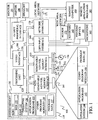
- FIG. 1 illustrates an example of a suitable computing system environment 100 on which the invention may be implemented.
- the computing system environment 100 is only one example of a suitable computing environment and is not intended to suggest any limitation as to the scope of use or functionality of the invention. Neither should the computing environment 100 be interpreted as having any dependency or requirement relating to any one or combination of components illustrated in the exemplary operating environment 100.
- the invention is operational with numerous other general purpose or special purpose computing system environments or configurations.
- Examples of well-known computing systems, environments, and/or configurations that may be suitable for use with the invention include, but are not limited to, personal computers, server computers, hand-held or laptop devices, multiprocessor systems, microprocessor-based systems, set top boxes, programmable consumer electronics, network PCs, minicomputers, mainframe computers, telephony systems, distributed computing environments that include any of the above systems or devices, and the like.
- the invention may be described in the general context of computer-executable instructions, such as program modules, being executed by a computer.
- program modules include routines, programs, objects, components, data structures, etc. that perform particular tasks or implement particular abstract data types.
- the invention may also be practiced in distributed computing environments where tasks are performed by remote processing devices that are linked through a communications network.
- program modules may be located in both local and remote computer storage media including memory storage devices.
- an exemplary system for implementing the invention includes a general-purpose computing device in the form of a computer 110.
- Components of computer 110 may include, but are not limited to, a processing unit 120, a system memory 130, and a system bus 121 that couples various system components including the system memory to the processing unit 120.
- the system bus 121 may be any of several types of bus structures including a memory bus or memory controller, a peripheral bus, and a local bus using any of a variety of bus architectures.
- such architectures include Industry Standard Architecture (ISA) bus, Micro Channel Architecture (MCA) bus, Enhanced ISA (EISA) bus, Video Electronics Standards Association (VESA) local bus, and Peripheral Component Interconnect (PCI) bus also known as Mezzanine bus.
- ISA Industry Standard Architecture
- MCA Micro Channel Architecture
- EISA Enhanced ISA
- VESA Video Electronics Standards Association
- PCI Peripheral Component Interconnect
- Computer 110 typically includes a variety of computer readable media.
- Computer readable media can be any available media that can be accessed by computer 110 and includes both volatile and nonvolatile media, removable and non-removable media.
- Computer readable media may comprise computer storage media and communication media.
- Computer storage media includes both volatile and nonvolatile, removable and non-removable media implemented in any method or technology for storage of information such as computer readable instructions, data structures, program modules or other data.
- Computer storage media includes, but is not limited to, RAM, ROM, EEPROM, flash memory or other memory technology, CD-ROM, digital versatile disks (DVD) or other optical disk storage, magnetic cassettes, magnetic tape, magnetic disk storage or other magnetic storage devices, or any other medium which can be used to store the desired information and which can be accessed by computer 110.
- Communication media typically embodies computer readable instructions, data structures, program modules or other data in a modulated data signal such as a carrier wave or other transport mechanism and includes any information delivery media.
- modulated data signal means a signal that has one or more of its characteristics set or changed in such a manner as to encode information in the signal.
- communication media includes wired media such as a wired network or direct-wired connection, and wireless media such as acoustic, RF, infrared and other wireless media. Combinations of any of the above should also be included within the scope of computer readable media.
- the system memory 130 includes computer storage media in the form of volatile and/or nonvolatile memory such as read only memory (ROM) 131 and random access memory (RAM) 132.
- ROM read only memory
- RAM random access memory
- BIOS basic input/output system
- RAM 132 typically contains data and/or program modules that are immediately accessible to and/or presently being operated on by processing unit 120.
- FIG. 1 illustrates operating system 134, application programs 135, other program modules 136, and program data 137.
- the computer 110 may also include other removable/non-removable volatile/nonvolatile computer storage media.
- FIG. 1 illustrates a hard disk drive 141 that reads from or writes to non-removable, nonvolatile magnetic media, a magnetic disk drive 151 that reads from or writes to a removable, nonvolatile magnetic disk 152, and an optical disk drive 155 that reads from or writes to a removable, nonvolatile optical disk 156 such as a CD ROM or other optical media.
- removable/non-removable, volatile/nonvolatile computer storage media that can be used in the exemplary operating environment include, but are not limited to, magnetic tape cassettes, flash memory cards, digital versatile disks, digital video tape, solid state RAM, solid state ROM, and the like.
- the hard disk drive 141 is typically connected to the system bus 121 through a non-removable memory interface such as interface 140, and magnetic disk drive 151 and optical disk drive 155 are typically connected to the system bus 121 by a removable memory interface, such as interface 150.
- hard disk drive 141 is illustrated as storing operating system 144, application programs 145, other program modules 146, and program data 147. Note that these components can either be the same as or different from operating system 134, application programs 135, other program modules 136, and program data 137. Operating system 144, application programs 145, other program modules 146, and program data 147 are given different numbers here to illustrate that, at a minimum, they are different copies.
- a user may enter commands and information into the computer 110 through input devices such as a keyboard 162, a microphone 163, and a pointing device 161, such as a mouse, trackball or touch pad.
- Other input devices may include a joystick, game pad, satellite dish, scanner, or the like.
- a monitor 191 or other type of display device is also connected to the system bus 121 via an interface, such as a video interface 190.
- computers may also include other peripheral output devices such as speakers 197 and printer 196, which may be connected through an output peripheral interface 190.
- the computer 110 may operate in a networked environment using logical connections to one or more remote computers, such as a remote computer 180.
- the remote computer 180 may be a personal computer, a hand-held device, a server, a router, a network PC, a peer device or other common network node, and typically includes many or all of the elements described above relative to the computer 110.
- the logical connections depicted in FIG. 1 include a local area network (LAN) 171 and a wide area network (WAN) 173, but may also include other networks.
- LAN local area network
- WAN wide area network
- Such networking environments are commonplace in offices, enterprise-wide computer networks, intranets and the Internet.
- the computer 110 When used in a LAN networking environment, the computer 110 is connected to the LAN 171 through a network interface or adapter 170. When used in a WAN networking environment, the computer 110 typically includes a modem 172 or other means for establishing communications over the WAN 173, such as the Internet.
- the modem 172 which may be internal or external, may be connected to the system bus 121 via the user input interface 160, or other appropriate mechanism.
- program modules depicted relative to the computer 110, or portions thereof may be stored in the remote memory storage device.
- FIG. 1 illustrates remote application programs 185 as residing on remote computer 180. It will be appreciated that the network connections shown are exemplary and other means of establishing a communications link between the computers may be used.
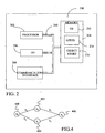
- FIG. 2 is a block diagram of a mobile device 200, which is an exemplary computing environment.
- Mobile device 200 includes a microprocessor 202, memory 204, input/output (I/O) components 206, and a communication interface 208 for communicating with remote computers or other mobile devices.
- I/O input/output
- the afore-mentioned components are coupled for communication with one another over a suitable bus 210.
- Memory 204 is implemented as non-volatile electronic memory such as random access memory (RAM) with a battery back-up module (not shown) such that information stored in memory 204 is not lost when the general power to mobile device 200 is shut down.
- RAM random access memory
- a portion of memory 204 is preferably allocated as addressable memory for program execution, while another portion of memory 204 is preferably used for storage, such as to simulate storage on a disk drive.
- Memory 204 includes an operating system 212, application programs 214 as well as an object store 216.
- operating system 212 is preferably executed by processor 202 from memory 204.
- Operating system 212 in one preferred embodiment, is a WINDOWS ® CE brand operating system commercially available from Microsoft Corporation.
- Operating system 212 is preferably designed for mobile devices, and implements database features that can be utilized by applications 214 through a set of exposed application programming interfaces and methods.
- the objects in object store 216 are maintained by applications 214 and operating system 212, at least partially in response to calls to the exposed application programming interfaces and methods.
- Communication interface 208 represents numerous devices and technologies that allow mobile device 200 to send and receive information.
- the devices include wired and wireless modems, satellite receivers and broadcast tuners to name a few.
- Mobile device 200 can also be directly connected to a computer to exchange data therewith.
- communication interface 208 can be an infrared transceiver or a serial or parallel communication connection, all of which are capable of transmitting streaming information.
- Input/output components 206 include a variety of input devices such as a touch-sensitive screen, buttons, rollers, and a microphone as well as a variety of output devices including an audio generator, a vibrating device, and a display.
- input devices such as a touch-sensitive screen, buttons, rollers, and a microphone
- output devices including an audio generator, a vibrating device, and a display.
- the devices listed above are by way of example and need not all be present on mobile device 200.
- other input/output devices may be attached to or found with mobile device 200 within the scope of the present invention.
- the present invention provides a generative model of speech.
- speech is represented as an attempt by the speaker to phonetically implement a linguistic definition of a sequence of phonological units.
- the speaker produces a production-related value that follows a trajectory from a value associated with the end of a previous phonological unit toward a target associated with a current phonological unit.
- This trajectory is modeled as an interpolation between the value at the end of the previous phonological unit and the target value wherein the interpolation includes a time-dependent weight such that the weighting between the two interpolation points changes over the length of the phonological unit.
- the model of the present invention is referred to as a Hidden Trajectory Model, which is a special form of a Hidden-Dynamic Model in that the dynamics is specified by an explicit form of time dependency rather by a recursive form.
- This hidden trajectory model includes two layers, a dynamic or trajectory model component that describes hidden production-related parameters (such as vocal track resonance), and a mapping model component that translates the production-related parameters into observable acoustic features such as Mel-Frequency Cepstral Coefficients.
- the dynamic model predicts a sequence of trajectory values (z (1) ,..., z (t), ..., z (T)) for a production-related parameter given a phone sequence (u 1 , ..., u j , ..., u N ) with corresponding boundaries ( ⁇ 1 ... ⁇ N +1 ).
- the mapping model predicts a sequence of acoustic observation vectors given the sequence of trajectory values, the phone sequence and the phone boundaries.
- a separate set of trajectory parameters are trained for each phone in the language.
- the trajectory within a phone is determined based on the value of the trajectory at the beginning of the phone and the amount of time that has passed since the beginning of the phone.
- T u j is the target for the trajectory of phone u j
- ⁇ u j is a time constant associated with phone u j
- g 0 j is the initial value of the trajectory on entry into the phone.
- the parenthetical term on the right-hand side of equation 6 is a critical damping function.
- the trajectory computed in Equation 5 is a linear interpolation between the production-related dynamics value at the beginning of the phone g 0 j and a production-related target T u j , with a time-dependent interpolation weight ⁇ u j ( k )
- H m and h m are not phone dependent. In another embodiment, they are made dependent on phones, phone classes, or sub-phone units corresponding to HMM states arranged in the left-to-right manner.
- the predicted feature vectors for silence and noise are not dependent on the trajectory of the production-related value. This is consistent with the generative model where silence and noise represent an interruption in speech generation.
- z t , u N ⁇ o t ; H m ⁇ z ( t ) + h m , R m
- the model parameters T u j , ⁇ u j , H m h m , Q , R m are trained using an Expectation-Maximization training algorithm.
- the algorithm includes an E-step in which a set of training observation vectors are used with an initial estimate of the model parameters to develop sufficient statistics to predict the value of the certain hidden variables including mixture weights, the trajectory, and the square of the trajectory.
- o n p o n
- m ⁇ P m ⁇ m ⁇ 1 M p o n
- o n , m H m TRANS ⁇ R m - 1 ⁇ H m + Q - 1 - 1 [ H m TRANS ⁇ R m - 1 ⁇ o k n - h m + Q - 1 ⁇ g k n ) ] E z k n ⁇ z k n trans
- o n , m E [ z k ⁇
- initial estimates of the model parameters must be provided.
- initial estimates for T u j and ⁇ u j are selected using combined knowledge of the Klatt speech synthesizer and some spectrogram analysis results.
- Alignment boundaries ( ⁇ 1 ... ⁇ N +1 ) are then determined for the set of training observation vectors using an existing HMM system and techniques for alignment that are well known.
- a set of trajectories g(t) is estimated using equation 5 above.
- R m and Q are assumed to be diagonal matrices so only the diagonals of the matrices are calculated.
- T ⁇ is the update for T
- g 0 n k g K j - 1 - T ⁇ 1 + ⁇ k ⁇ exp - ⁇ k
- T is the previously estimated target
- the E-step and the M-step may be iterated a number of times to come to a final set of model parameters. Once the final set of parameters has been determined, they can be used to decode an observed set of acoustic vectors.
- the decoding task involves finding a phone sequence that most likely generated a sequence of acoustic observations.
- decoding is performed using a Finite-State Transducer in which each phone is represented by an edge connecting two states where the states' positions in time are determined during decoding.
- e represents a single phone
- Equation 40 when the first time index is reached, a further recursion is performed by evaluating equation 35 using the state at the beginning of the current edge and the time index of the beginning of the current edge. This recursion is indicated by the last term in Equation 40.
- the duration models in Equation 39 ( P ( ⁇ t
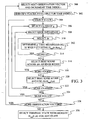
- Equation 32-42 is performed in an iterative fashion under one embodiment of the present invention as described below with reference to the flow diagram of FIG. 3 .
- a set of best path scores is determined at each frame of the observed signal.
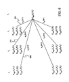
- a separate H c ( g ) ( t , n ) value as found in Equation 35 above is determined for each class of trajectory.
- the H c(g) (t,n) values of FIG. 5 would be generated, provided that there are only three classes of trajectories.
- values 500, 502, and 504 would be generated during the first frame (time index t 1 ) for classes c(g)1, c(g)2, and c(g)3, respectively, in state n 1 .
- Values 506, 508 and 510 would be generated during the second frame (time index t 2 ) for classes c(g)1, c(g)2, and c(g)3, respectively, in state n 1 .
- FIG. 6 shows the diagram of FIG. 5 during the calculation of scores for the fourth frame of the observed vectors. FIG. 6 is referred to in the description of FIG. 3 below.
- the first observed vector is selected and the time index is set to 1.
- states that are available during the time index are identified.
- a state is available for a time index if the time index is equal to the number of edges between the state and beginning state no of the finite state system. For example, in the simplified state system of FIG. 4 , there are four states: 400, 402, 404 and 406.
- time index 1 only states 402 and 406 are available because there have not been enough observed feature vectors to have at least one feature vector for each edge between state 400 and state 406.
- states 402, 404, and 406 would all be available.
- states are not considered available if the time index is some amount greater than the number of edges between the state and beginning state n 0 . This reduces the number of computations that are performed by eliminating temporal positions for states that are unlikely to occur.
- steps 304 and 306 result in the selection of state n 2 and class c(g)1. This is the state and class for which a H c(g) (t,n) value will be generated.
- an edge into the selected state is selected. For example, edge e 3 of FIG. 4 would be selected for state 406.
- a ⁇ t is selected at step 310.
- a g' is identified that maximizes the calculation shown in equation 36 for the currently selected class of trajectories, the selected edge and the selected ⁇ t .
- the computation of equation 36 is performed recursively along all of the time indices crossed by ⁇ t and is dependent on the value of H c ( g ') ( t - ⁇ t , n e 1 ) associated with the state at the beginning of the selected edge. Note that the value H c(g') ( t - ⁇ t , n e 1 ) has been previously calculated using the method of Figure 3 at an earlier time index and that the value is selected based on the class of the g' that is optimal for equation 36.
- step 314 the method determines if there are additional ⁇ t to be considered. If there are, the process returns to step 310 to select a different ⁇ t . Step 312 is then repeated using the new ⁇ t to identify a new score using equation 36.
- the method determines if there are any more edges that end at the current state. If there are, the process returns to step 308 and steps 310, 312, 314, and 316 are repeated to generate an edge score for the newly selected edge. For example, in FIG. 6 , an edge score would be generated for edge e 4 .
- the highest edge score is selected as the H c(g) (t,n) path score for the selected class and state.
- the process determines if there are additional classes that need a H c ( g ) ( t,n ) path score. If there are, the process returns to step 306 to select the next class of trajectories. Steps 308-320 are then repeated to generate a H c ( g ) ( t , n ) path score for the newly selected class. When there are no more classes at step 322, the process determines if there are any more available states that need to be scored at step 324. If there are, the process returns to step 304 to select the next available state and steps 306-322 are repeated to generate a collection of H c ( g ) ( t , n ) path scores for the state.
- the process determines if there is another observation vector at step 326. If there is, the process returns to step 300 where the next observation vector is selected and the time index is incremented by one. Steps 302-324 are then repeated for the new vector and time index.
- the terminal state with the highest score, regardless of class is selected as the final state in the decoded path. The decoded path is then determined by tracing back along the edge and ⁇ t that were used to generate the highest H c(g) (t,n) score at each state.
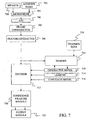
- FIG. 7 provides a block diagram of a speech recognition system in which the present invention can be used.
- a speaker 700 either a trainer or a user, speaks into a microphone 704.
- Microphone 704 also receives additive noise from one or more noise sources 702.
- the audio signals detected by microphone 704 are converted into electrical signals that are provided to analog-to-digital converter 706.
- A-to-D converter 706 converts the analog signal from microphone 704 into a series of digital values. In several embodiments, A-to-D converter 706 samples the analog signal at 16 kHz and 16 bits per sample, thereby creating 32 kilobytes of speech data per second. These digital values are provided to a frame constructor 707, which, in one embodiment, groups the values into 25 millisecond frames that start 10 milliseconds apart.
- the frames of data created by frame constructor 707 are provided to feature extractor 708, which extracts a feature from each frame.
- feature extraction modules include modules for performing Linear Predictive Coding (LPC), LPC derived cepstrum, Perceptive Linear Prediction (PLP), Auditory model feature extraction, and Mel-Frequency Cepstrum Coefficients (MFCC) feature extraction. Note that the invention is not limited to these feature extraction modules and that other modules may be used within the context of the present invention.
- this series of feature vectors is provided to a trainer 724, which uses the feature vectors and a training text 726 to train the generative model 728 of the present invention.
- the EM training algorithm described above may be used to train the generative model.
- the feature vectors are provided to a decoder 712, which identifies a most likely sequence of words based on the stream of feature vectors, a lexicon 714, a language model 716, and the generative model 728.
- lexicon 714 defines the finite state network that is traversed by decoder 712 to identify a word from a sequence of feature vectors.
- Confidence measure module 720 identifies which words are most likely to have been improperly identified by the speech recognizer, based in part on a secondary acoustic model(not shown). Confidence measure module 720 then provides the sequence of hypothesis words to an output module 722 along with identifiers indicating which words may have been improperly identified. Those skilled in the art will recognize that confidence measure module 720 is not necessary for the practice of the present invention.
Landscapes
- Engineering & Computer Science (AREA)
- Acoustics & Sound (AREA)
- Health & Medical Sciences (AREA)
- Audiology, Speech & Language Pathology (AREA)
- Human Computer Interaction (AREA)
- Physics & Mathematics (AREA)
- Computational Linguistics (AREA)
- Multimedia (AREA)
- Mobile Radio Communication Systems (AREA)
- Image Analysis (AREA)
- Machine Translation (AREA)
- Noise Elimination (AREA)
- Complex Calculations (AREA)
Applications Claiming Priority (6)
| Application Number | Priority Date | Filing Date | Title |
|---|---|---|---|
| US39816602P | 2002-07-23 | 2002-07-23 | |
| US398166P | 2002-07-23 | ||
| US40597102P | 2002-08-26 | 2002-08-26 | |
| US405971P | 2002-08-26 | ||
| US10/267,522 US7050975B2 (en) | 2002-07-23 | 2002-10-09 | Method of speech recognition using time-dependent interpolation and hidden dynamic value classes |
| US267522 | 2002-10-09 |
Publications (3)
| Publication Number | Publication Date |
|---|---|
| EP1385147A2 EP1385147A2 (en) | 2004-01-28 |
| EP1385147A3 EP1385147A3 (en) | 2005-04-20 |
| EP1385147B1 true EP1385147B1 (en) | 2008-05-07 |
Family
ID=30003734
Family Applications (1)
| Application Number | Title | Priority Date | Filing Date |
|---|---|---|---|
| EP03014848A Expired - Lifetime EP1385147B1 (en) | 2002-07-23 | 2003-06-30 | Method of speech recognition using time-dependent interpolation and hidden dynamic value classes |
Country Status (5)
| Country | Link |
|---|---|
| US (2) | US7050975B2 (enExample) |
| EP (1) | EP1385147B1 (enExample) |
| JP (1) | JP4515054B2 (enExample) |
| AT (1) | ATE394773T1 (enExample) |
| DE (1) | DE60320719D1 (enExample) |
Families Citing this family (22)
| Publication number | Priority date | Publication date | Assignee | Title |
|---|---|---|---|---|
| US7209881B2 (en) * | 2001-12-20 | 2007-04-24 | Matsushita Electric Industrial Co., Ltd. | Preparing acoustic models by sufficient statistics and noise-superimposed speech data |
| US7174292B2 (en) * | 2002-05-20 | 2007-02-06 | Microsoft Corporation | Method of determining uncertainty associated with acoustic distortion-based noise reduction |
| US7103540B2 (en) * | 2002-05-20 | 2006-09-05 | Microsoft Corporation | Method of pattern recognition using noise reduction uncertainty |
| US7050975B2 (en) * | 2002-07-23 | 2006-05-23 | Microsoft Corporation | Method of speech recognition using time-dependent interpolation and hidden dynamic value classes |
| FR2846458B1 (fr) * | 2002-10-25 | 2005-02-25 | France Telecom | Procede de traitement automatique d'un signal de parole. |
| US9117460B2 (en) * | 2004-05-12 | 2015-08-25 | Core Wireless Licensing S.A.R.L. | Detection of end of utterance in speech recognition system |
| US7409346B2 (en) * | 2004-11-05 | 2008-08-05 | Microsoft Corporation | Two-stage implementation for phonetic recognition using a bi-directional target-filtering model of speech coarticulation and reduction |
| US7565284B2 (en) * | 2004-11-05 | 2009-07-21 | Microsoft Corporation | Acoustic models with structured hidden dynamics with integration over many possible hidden trajectories |
| US7519531B2 (en) * | 2005-03-30 | 2009-04-14 | Microsoft Corporation | Speaker adaptive learning of resonance targets in a hidden trajectory model of speech coarticulation |
| US7805301B2 (en) * | 2005-07-01 | 2010-09-28 | Microsoft Corporation | Covariance estimation for pattern recognition |
| US7653535B2 (en) | 2005-12-15 | 2010-01-26 | Microsoft Corporation | Learning statistically characterized resonance targets in a hidden trajectory model |
| US8010356B2 (en) * | 2006-02-17 | 2011-08-30 | Microsoft Corporation | Parameter learning in a hidden trajectory model |
| US7877256B2 (en) * | 2006-02-17 | 2011-01-25 | Microsoft Corporation | Time synchronous decoding for long-span hidden trajectory model |
| US7805308B2 (en) * | 2007-01-19 | 2010-09-28 | Microsoft Corporation | Hidden trajectory modeling with differential cepstra for speech recognition |
| US9020816B2 (en) * | 2008-08-14 | 2015-04-28 | 21Ct, Inc. | Hidden markov model for speech processing with training method |
| US9009039B2 (en) * | 2009-06-12 | 2015-04-14 | Microsoft Technology Licensing, Llc | Noise adaptive training for speech recognition |
| EP2539888B1 (en) | 2010-02-22 | 2015-05-20 | Nuance Communications, Inc. | Online maximum-likelihood mean and variance normalization for speech recognition |
| TWI442384B (zh) * | 2011-07-26 | 2014-06-21 | Ind Tech Res Inst | 以麥克風陣列為基礎之語音辨識系統與方法 |
| JP6301664B2 (ja) | 2014-01-31 | 2018-03-28 | 株式会社東芝 | 変換装置、パターン認識システム、変換方法およびプログラム |
| US9953646B2 (en) | 2014-09-02 | 2018-04-24 | Belleau Technologies | Method and system for dynamic speech recognition and tracking of prewritten script |
| US10354642B2 (en) * | 2017-03-03 | 2019-07-16 | Microsoft Technology Licensing, Llc | Hyperarticulation detection in repetitive voice queries using pairwise comparison for improved speech recognition |
| JP6599914B2 (ja) * | 2017-03-09 | 2019-10-30 | 株式会社東芝 | 音声認識装置、音声認識方法およびプログラム |
Family Cites Families (7)
| Publication number | Priority date | Publication date | Assignee | Title |
|---|---|---|---|---|
| US4980917A (en) * | 1987-11-18 | 1990-12-25 | Emerson & Stern Associates, Inc. | Method and apparatus for determining articulatory parameters from speech data |
| JP2986345B2 (ja) * | 1993-10-18 | 1999-12-06 | インターナショナル・ビジネス・マシーンズ・コーポレイション | 音声記録指標化装置及び方法 |
| GB2290684A (en) * | 1994-06-22 | 1996-01-03 | Ibm | Speech synthesis using hidden Markov model to determine speech unit durations |
| JPH0895592A (ja) * | 1994-09-21 | 1996-04-12 | Nippon Telegr & Teleph Corp <Ntt> | パターン認識方法 |
| JPH0822296A (ja) * | 1994-07-07 | 1996-01-23 | Nippon Telegr & Teleph Corp <Ntt> | パターン認識方法 |
| US5937384A (en) * | 1996-05-01 | 1999-08-10 | Microsoft Corporation | Method and system for speech recognition using continuous density hidden Markov models |
| US7050975B2 (en) * | 2002-07-23 | 2006-05-23 | Microsoft Corporation | Method of speech recognition using time-dependent interpolation and hidden dynamic value classes |
-
2002
- 2002-10-09 US US10/267,522 patent/US7050975B2/en not_active Expired - Fee Related
-
2003
- 2003-06-30 DE DE60320719T patent/DE60320719D1/de not_active Expired - Lifetime
- 2003-06-30 EP EP03014848A patent/EP1385147B1/en not_active Expired - Lifetime
- 2003-06-30 AT AT03014848T patent/ATE394773T1/de not_active IP Right Cessation
- 2003-07-23 JP JP2003278640A patent/JP4515054B2/ja not_active Expired - Fee Related
-
2005
- 2005-12-06 US US11/294,858 patent/US7206741B2/en not_active Expired - Lifetime
Also Published As
| Publication number | Publication date |
|---|---|
| US20060085191A1 (en) | 2006-04-20 |
| JP4515054B2 (ja) | 2010-07-28 |
| JP2004054298A (ja) | 2004-02-19 |
| US7206741B2 (en) | 2007-04-17 |
| ATE394773T1 (de) | 2008-05-15 |
| US7050975B2 (en) | 2006-05-23 |
| EP1385147A2 (en) | 2004-01-28 |
| EP1385147A3 (en) | 2005-04-20 |
| DE60320719D1 (de) | 2008-06-19 |
| US20040019483A1 (en) | 2004-01-29 |
Similar Documents
| Publication | Publication Date | Title |
|---|---|---|
| EP1385147B1 (en) | Method of speech recognition using time-dependent interpolation and hidden dynamic value classes | |
| US8280733B2 (en) | Automatic speech recognition learning using categorization and selective incorporation of user-initiated corrections | |
| EP1465154B1 (en) | Method of speech recognition using variational inference with switching state space models | |
| US7617104B2 (en) | Method of speech recognition using hidden trajectory Hidden Markov Models | |
| US20110077943A1 (en) | System for generating language model, method of generating language model, and program for language model generation | |
| US7627473B2 (en) | Hidden conditional random field models for phonetic classification and speech recognition | |
| JP6031316B2 (ja) | 音声認識装置、誤り修正モデル学習方法、及びプログラム | |
| EP1701337B1 (en) | Method of speech recognition | |
| US7409346B2 (en) | Two-stage implementation for phonetic recognition using a bi-directional target-filtering model of speech coarticulation and reduction | |
| US7565284B2 (en) | Acoustic models with structured hidden dynamics with integration over many possible hidden trajectories | |
| US7346510B2 (en) | Method of speech recognition using variables representing dynamic aspects of speech |
Legal Events
| Date | Code | Title | Description |
|---|---|---|---|
| PUAI | Public reference made under article 153(3) epc to a published international application that has entered the european phase |
Free format text: ORIGINAL CODE: 0009012 |
|
| AK | Designated contracting states |
Kind code of ref document: A2 Designated state(s): AT BE BG CH CY CZ DE DK EE ES FI FR GB GR HU IE IT LI LU MC NL PT RO SE SI SK TR |
|
| AX | Request for extension of the european patent |
Extension state: AL LT LV MK |
|
| PUAL | Search report despatched |
Free format text: ORIGINAL CODE: 0009013 |
|
| RIC1 | Information provided on ipc code assigned before grant |
Ipc: 7G 10L 15/14 A |
|
| AK | Designated contracting states |
Kind code of ref document: A3 Designated state(s): AT BE BG CH CY CZ DE DK EE ES FI FR GB GR HU IE IT LI LU MC NL PT RO SE SI SK TR |
|
| AX | Request for extension of the european patent |
Extension state: AL LT LV MK |
|
| 17P | Request for examination filed |
Effective date: 20050825 |
|
| AKX | Designation fees paid |
Designated state(s): AT BE BG CH CY CZ DE DK EE ES FI FR GB GR HU IE IT LI LU MC NL PT RO SE SI SK TR |
|
| 17Q | First examination report despatched |
Effective date: 20051007 |
|
| GRAP | Despatch of communication of intention to grant a patent |
Free format text: ORIGINAL CODE: EPIDOSNIGR1 |
|
| GRAS | Grant fee paid |
Free format text: ORIGINAL CODE: EPIDOSNIGR3 |
|
| GRAA | (expected) grant |
Free format text: ORIGINAL CODE: 0009210 |
|
| AK | Designated contracting states |
Kind code of ref document: B1 Designated state(s): AT BE BG CH CY CZ DE DK EE ES FI FR GB GR HU IE IT LI LU MC NL PT RO SE SI SK TR |
|
| REG | Reference to a national code |
Ref country code: GB Ref legal event code: FG4D |
|
| REG | Reference to a national code |
Ref country code: CH Ref legal event code: EP |
|
| REG | Reference to a national code |
Ref country code: IE Ref legal event code: FG4D Free format text: LANGUAGE OF EP DOCUMENT: FRENCH |
|
| REF | Corresponds to: |
Ref document number: 60320719 Country of ref document: DE Date of ref document: 20080619 Kind code of ref document: P |
|
| PG25 | Lapsed in a contracting state [announced via postgrant information from national office to epo] |
Ref country code: SI Free format text: LAPSE BECAUSE OF FAILURE TO SUBMIT A TRANSLATION OF THE DESCRIPTION OR TO PAY THE FEE WITHIN THE PRESCRIBED TIME-LIMIT Effective date: 20080507 |
|
| PG25 | Lapsed in a contracting state [announced via postgrant information from national office to epo] |
Ref country code: NL Free format text: LAPSE BECAUSE OF FAILURE TO SUBMIT A TRANSLATION OF THE DESCRIPTION OR TO PAY THE FEE WITHIN THE PRESCRIBED TIME-LIMIT Effective date: 20080507 Ref country code: FI Free format text: LAPSE BECAUSE OF FAILURE TO SUBMIT A TRANSLATION OF THE DESCRIPTION OR TO PAY THE FEE WITHIN THE PRESCRIBED TIME-LIMIT Effective date: 20080507 Ref country code: ES Free format text: LAPSE BECAUSE OF FAILURE TO SUBMIT A TRANSLATION OF THE DESCRIPTION OR TO PAY THE FEE WITHIN THE PRESCRIBED TIME-LIMIT Effective date: 20080818 |
|
| NLV1 | Nl: lapsed or annulled due to failure to fulfill the requirements of art. 29p and 29m of the patents act | ||
| PG25 | Lapsed in a contracting state [announced via postgrant information from national office to epo] |
Ref country code: AT Free format text: LAPSE BECAUSE OF FAILURE TO SUBMIT A TRANSLATION OF THE DESCRIPTION OR TO PAY THE FEE WITHIN THE PRESCRIBED TIME-LIMIT Effective date: 20080507 |
|
| PG25 | Lapsed in a contracting state [announced via postgrant information from national office to epo] |
Ref country code: CZ Free format text: LAPSE BECAUSE OF FAILURE TO SUBMIT A TRANSLATION OF THE DESCRIPTION OR TO PAY THE FEE WITHIN THE PRESCRIBED TIME-LIMIT Effective date: 20080507 Ref country code: DK Free format text: LAPSE BECAUSE OF FAILURE TO SUBMIT A TRANSLATION OF THE DESCRIPTION OR TO PAY THE FEE WITHIN THE PRESCRIBED TIME-LIMIT Effective date: 20080507 Ref country code: PT Free format text: LAPSE BECAUSE OF FAILURE TO SUBMIT A TRANSLATION OF THE DESCRIPTION OR TO PAY THE FEE WITHIN THE PRESCRIBED TIME-LIMIT Effective date: 20081007 Ref country code: MC Free format text: LAPSE BECAUSE OF NON-PAYMENT OF DUE FEES Effective date: 20080630 Ref country code: SE Free format text: LAPSE BECAUSE OF FAILURE TO SUBMIT A TRANSLATION OF THE DESCRIPTION OR TO PAY THE FEE WITHIN THE PRESCRIBED TIME-LIMIT Effective date: 20080807 |
|
| REG | Reference to a national code |
Ref country code: CH Ref legal event code: PL |
|
| PG25 | Lapsed in a contracting state [announced via postgrant information from national office to epo] |
Ref country code: BE Free format text: LAPSE BECAUSE OF FAILURE TO SUBMIT A TRANSLATION OF THE DESCRIPTION OR TO PAY THE FEE WITHIN THE PRESCRIBED TIME-LIMIT Effective date: 20080507 Ref country code: RO Free format text: LAPSE BECAUSE OF FAILURE TO SUBMIT A TRANSLATION OF THE DESCRIPTION OR TO PAY THE FEE WITHIN THE PRESCRIBED TIME-LIMIT Effective date: 20080507 Ref country code: SK Free format text: LAPSE BECAUSE OF FAILURE TO SUBMIT A TRANSLATION OF THE DESCRIPTION OR TO PAY THE FEE WITHIN THE PRESCRIBED TIME-LIMIT Effective date: 20080507 |
|
| PLBE | No opposition filed within time limit |
Free format text: ORIGINAL CODE: 0009261 |
|
| STAA | Information on the status of an ep patent application or granted ep patent |
Free format text: STATUS: NO OPPOSITION FILED WITHIN TIME LIMIT |
|
| REG | Reference to a national code |
Ref country code: IE Ref legal event code: MM4A |
|
| 26N | No opposition filed |
Effective date: 20090210 |
|
| PG25 | Lapsed in a contracting state [announced via postgrant information from national office to epo] |
Ref country code: IE Free format text: LAPSE BECAUSE OF NON-PAYMENT OF DUE FEES Effective date: 20080630 Ref country code: BG Free format text: LAPSE BECAUSE OF FAILURE TO SUBMIT A TRANSLATION OF THE DESCRIPTION OR TO PAY THE FEE WITHIN THE PRESCRIBED TIME-LIMIT Effective date: 20080807 Ref country code: EE Free format text: LAPSE BECAUSE OF FAILURE TO SUBMIT A TRANSLATION OF THE DESCRIPTION OR TO PAY THE FEE WITHIN THE PRESCRIBED TIME-LIMIT Effective date: 20080507 |
|
| PG25 | Lapsed in a contracting state [announced via postgrant information from national office to epo] |
Ref country code: CH Free format text: LAPSE BECAUSE OF NON-PAYMENT OF DUE FEES Effective date: 20080630 Ref country code: LI Free format text: LAPSE BECAUSE OF NON-PAYMENT OF DUE FEES Effective date: 20080630 |
|
| PG25 | Lapsed in a contracting state [announced via postgrant information from national office to epo] |
Ref country code: HU Free format text: LAPSE BECAUSE OF FAILURE TO SUBMIT A TRANSLATION OF THE DESCRIPTION OR TO PAY THE FEE WITHIN THE PRESCRIBED TIME-LIMIT Effective date: 20081108 Ref country code: LU Free format text: LAPSE BECAUSE OF NON-PAYMENT OF DUE FEES Effective date: 20080630 Ref country code: CY Free format text: LAPSE BECAUSE OF FAILURE TO SUBMIT A TRANSLATION OF THE DESCRIPTION OR TO PAY THE FEE WITHIN THE PRESCRIBED TIME-LIMIT Effective date: 20080507 |
|
| PG25 | Lapsed in a contracting state [announced via postgrant information from national office to epo] |
Ref country code: TR Free format text: LAPSE BECAUSE OF FAILURE TO SUBMIT A TRANSLATION OF THE DESCRIPTION OR TO PAY THE FEE WITHIN THE PRESCRIBED TIME-LIMIT Effective date: 20080507 |
|
| PG25 | Lapsed in a contracting state [announced via postgrant information from national office to epo] |
Ref country code: GR Free format text: LAPSE BECAUSE OF FAILURE TO SUBMIT A TRANSLATION OF THE DESCRIPTION OR TO PAY THE FEE WITHIN THE PRESCRIBED TIME-LIMIT Effective date: 20080808 |
|
| REG | Reference to a national code |
Ref country code: DE Ref legal event code: R082 Ref document number: 60320719 Country of ref document: DE Representative=s name: GRUENECKER, KINKELDEY, STOCKMAIR & SCHWANHAEUS, DE |
|
| REG | Reference to a national code |
Ref country code: GB Ref legal event code: 732E Free format text: REGISTERED BETWEEN 20150108 AND 20150114 |
|
| REG | Reference to a national code |
Ref country code: DE Ref legal event code: R082 Ref document number: 60320719 Country of ref document: DE Representative=s name: GRUENECKER PATENT- UND RECHTSANWAELTE PARTG MB, DE Effective date: 20150126 Ref country code: DE Ref legal event code: R081 Ref document number: 60320719 Country of ref document: DE Owner name: MICROSOFT TECHNOLOGY LICENSING, LLC, REDMOND, US Free format text: FORMER OWNER: MICROSOFT CORP., REDMOND, WASH., US Effective date: 20150126 |
|
| REG | Reference to a national code |
Ref country code: FR Ref legal event code: TP Owner name: MICROSOFT TECHNOLOGY LICENSING, LLC, US Effective date: 20150724 |
|
| REG | Reference to a national code |
Ref country code: FR Ref legal event code: PLFP Year of fee payment: 14 |
|
| REG | Reference to a national code |
Ref country code: FR Ref legal event code: PLFP Year of fee payment: 15 |
|
| REG | Reference to a national code |
Ref country code: FR Ref legal event code: PLFP Year of fee payment: 16 |
|
| PGFP | Annual fee paid to national office [announced via postgrant information from national office to epo] |
Ref country code: IT Payment date: 20190620 Year of fee payment: 17 Ref country code: DE Payment date: 20190618 Year of fee payment: 17 |
|
| PGFP | Annual fee paid to national office [announced via postgrant information from national office to epo] |
Ref country code: FR Payment date: 20190510 Year of fee payment: 17 |
|
| PGFP | Annual fee paid to national office [announced via postgrant information from national office to epo] |
Ref country code: GB Payment date: 20190626 Year of fee payment: 17 |
|
| REG | Reference to a national code |
Ref country code: DE Ref legal event code: R119 Ref document number: 60320719 Country of ref document: DE |
|
| GBPC | Gb: european patent ceased through non-payment of renewal fee |
Effective date: 20200630 |
|
| PG25 | Lapsed in a contracting state [announced via postgrant information from national office to epo] |
Ref country code: FR Free format text: LAPSE BECAUSE OF NON-PAYMENT OF DUE FEES Effective date: 20200630 Ref country code: GB Free format text: LAPSE BECAUSE OF NON-PAYMENT OF DUE FEES Effective date: 20200630 |
|
| PG25 | Lapsed in a contracting state [announced via postgrant information from national office to epo] |
Ref country code: DE Free format text: LAPSE BECAUSE OF NON-PAYMENT OF DUE FEES Effective date: 20210101 |
|
| PG25 | Lapsed in a contracting state [announced via postgrant information from national office to epo] |
Ref country code: IT Free format text: LAPSE BECAUSE OF NON-PAYMENT OF DUE FEES Effective date: 20200630 |