EP1385000A1 - Method for making biochip - Google Patents
Method for making biochip Download PDFInfo
- Publication number
- EP1385000A1 EP1385000A1 EP02722893A EP02722893A EP1385000A1 EP 1385000 A1 EP1385000 A1 EP 1385000A1 EP 02722893 A EP02722893 A EP 02722893A EP 02722893 A EP02722893 A EP 02722893A EP 1385000 A1 EP1385000 A1 EP 1385000A1
- Authority
- EP
- European Patent Office
- Prior art keywords
- discharge
- sample
- substrate
- tray
- moving table
- Prior art date
- Legal status (The legal status is an assumption and is not a legal conclusion. Google has not performed a legal analysis and makes no representation as to the accuracy of the status listed.)
- Granted
Links
Images








Classifications
-
- B—PERFORMING OPERATIONS; TRANSPORTING
- B01—PHYSICAL OR CHEMICAL PROCESSES OR APPARATUS IN GENERAL
- B01J—CHEMICAL OR PHYSICAL PROCESSES, e.g. CATALYSIS OR COLLOID CHEMISTRY; THEIR RELEVANT APPARATUS
- B01J19/00—Chemical, physical or physico-chemical processes in general; Their relevant apparatus
- B01J19/0046—Sequential or parallel reactions, e.g. for the synthesis of polypeptides or polynucleotides; Apparatus and devices for combinatorial chemistry or for making molecular arrays
-
- B—PERFORMING OPERATIONS; TRANSPORTING
- B82—NANOTECHNOLOGY
- B82Y—SPECIFIC USES OR APPLICATIONS OF NANOSTRUCTURES; MEASUREMENT OR ANALYSIS OF NANOSTRUCTURES; MANUFACTURE OR TREATMENT OF NANOSTRUCTURES
- B82Y30/00—Nanotechnology for materials or surface science, e.g. nanocomposites
-
- B—PERFORMING OPERATIONS; TRANSPORTING
- B01—PHYSICAL OR CHEMICAL PROCESSES OR APPARATUS IN GENERAL
- B01J—CHEMICAL OR PHYSICAL PROCESSES, e.g. CATALYSIS OR COLLOID CHEMISTRY; THEIR RELEVANT APPARATUS
- B01J2219/00—Chemical, physical or physico-chemical processes in general; Their relevant apparatus
- B01J2219/00274—Sequential or parallel reactions; Apparatus and devices for combinatorial chemistry or for making arrays; Chemical library technology
- B01J2219/00277—Apparatus
- B01J2219/00351—Means for dispensing and evacuation of reagents
- B01J2219/00378—Piezoelectric or ink jet dispensers
-
- B—PERFORMING OPERATIONS; TRANSPORTING
- B01—PHYSICAL OR CHEMICAL PROCESSES OR APPARATUS IN GENERAL
- B01J—CHEMICAL OR PHYSICAL PROCESSES, e.g. CATALYSIS OR COLLOID CHEMISTRY; THEIR RELEVANT APPARATUS
- B01J2219/00—Chemical, physical or physico-chemical processes in general; Their relevant apparatus
- B01J2219/00274—Sequential or parallel reactions; Apparatus and devices for combinatorial chemistry or for making arrays; Chemical library technology
- B01J2219/00277—Apparatus
- B01J2219/00497—Features relating to the solid phase supports
- B01J2219/00527—Sheets
-
- B—PERFORMING OPERATIONS; TRANSPORTING
- B01—PHYSICAL OR CHEMICAL PROCESSES OR APPARATUS IN GENERAL
- B01J—CHEMICAL OR PHYSICAL PROCESSES, e.g. CATALYSIS OR COLLOID CHEMISTRY; THEIR RELEVANT APPARATUS
- B01J2219/00—Chemical, physical or physico-chemical processes in general; Their relevant apparatus
- B01J2219/00274—Sequential or parallel reactions; Apparatus and devices for combinatorial chemistry or for making arrays; Chemical library technology
- B01J2219/00583—Features relative to the processes being carried out
- B01J2219/00585—Parallel processes
-
- B—PERFORMING OPERATIONS; TRANSPORTING
- B01—PHYSICAL OR CHEMICAL PROCESSES OR APPARATUS IN GENERAL
- B01J—CHEMICAL OR PHYSICAL PROCESSES, e.g. CATALYSIS OR COLLOID CHEMISTRY; THEIR RELEVANT APPARATUS
- B01J2219/00—Chemical, physical or physico-chemical processes in general; Their relevant apparatus
- B01J2219/00274—Sequential or parallel reactions; Apparatus and devices for combinatorial chemistry or for making arrays; Chemical library technology
- B01J2219/00583—Features relative to the processes being carried out
- B01J2219/0059—Sequential processes
-
- B—PERFORMING OPERATIONS; TRANSPORTING
- B01—PHYSICAL OR CHEMICAL PROCESSES OR APPARATUS IN GENERAL
- B01J—CHEMICAL OR PHYSICAL PROCESSES, e.g. CATALYSIS OR COLLOID CHEMISTRY; THEIR RELEVANT APPARATUS
- B01J2219/00—Chemical, physical or physico-chemical processes in general; Their relevant apparatus
- B01J2219/00274—Sequential or parallel reactions; Apparatus and devices for combinatorial chemistry or for making arrays; Chemical library technology
- B01J2219/00583—Features relative to the processes being carried out
- B01J2219/00596—Solid-phase processes
-
- B—PERFORMING OPERATIONS; TRANSPORTING
- B01—PHYSICAL OR CHEMICAL PROCESSES OR APPARATUS IN GENERAL
- B01J—CHEMICAL OR PHYSICAL PROCESSES, e.g. CATALYSIS OR COLLOID CHEMISTRY; THEIR RELEVANT APPARATUS
- B01J2219/00—Chemical, physical or physico-chemical processes in general; Their relevant apparatus
- B01J2219/00274—Sequential or parallel reactions; Apparatus and devices for combinatorial chemistry or for making arrays; Chemical library technology
- B01J2219/00583—Features relative to the processes being carried out
- B01J2219/00603—Making arrays on substantially continuous surfaces
- B01J2219/00605—Making arrays on substantially continuous surfaces the compounds being directly bound or immobilised to solid supports
-
- B—PERFORMING OPERATIONS; TRANSPORTING
- B01—PHYSICAL OR CHEMICAL PROCESSES OR APPARATUS IN GENERAL
- B01J—CHEMICAL OR PHYSICAL PROCESSES, e.g. CATALYSIS OR COLLOID CHEMISTRY; THEIR RELEVANT APPARATUS
- B01J2219/00—Chemical, physical or physico-chemical processes in general; Their relevant apparatus
- B01J2219/00274—Sequential or parallel reactions; Apparatus and devices for combinatorial chemistry or for making arrays; Chemical library technology
- B01J2219/00583—Features relative to the processes being carried out
- B01J2219/00603—Making arrays on substantially continuous surfaces
- B01J2219/00659—Two-dimensional arrays
-
- B—PERFORMING OPERATIONS; TRANSPORTING
- B01—PHYSICAL OR CHEMICAL PROCESSES OR APPARATUS IN GENERAL
- B01J—CHEMICAL OR PHYSICAL PROCESSES, e.g. CATALYSIS OR COLLOID CHEMISTRY; THEIR RELEVANT APPARATUS
- B01J2219/00—Chemical, physical or physico-chemical processes in general; Their relevant apparatus
- B01J2219/00274—Sequential or parallel reactions; Apparatus and devices for combinatorial chemistry or for making arrays; Chemical library technology
- B01J2219/00583—Features relative to the processes being carried out
- B01J2219/00603—Making arrays on substantially continuous surfaces
- B01J2219/00677—Ex-situ synthesis followed by deposition on the substrate
-
- B—PERFORMING OPERATIONS; TRANSPORTING
- B01—PHYSICAL OR CHEMICAL PROCESSES OR APPARATUS IN GENERAL
- B01J—CHEMICAL OR PHYSICAL PROCESSES, e.g. CATALYSIS OR COLLOID CHEMISTRY; THEIR RELEVANT APPARATUS
- B01J2219/00—Chemical, physical or physico-chemical processes in general; Their relevant apparatus
- B01J2219/00274—Sequential or parallel reactions; Apparatus and devices for combinatorial chemistry or for making arrays; Chemical library technology
- B01J2219/0068—Means for controlling the apparatus of the process
- B01J2219/00686—Automatic
- B01J2219/00689—Automatic using computers
-
- B—PERFORMING OPERATIONS; TRANSPORTING
- B01—PHYSICAL OR CHEMICAL PROCESSES OR APPARATUS IN GENERAL
- B01J—CHEMICAL OR PHYSICAL PROCESSES, e.g. CATALYSIS OR COLLOID CHEMISTRY; THEIR RELEVANT APPARATUS
- B01J2219/00—Chemical, physical or physico-chemical processes in general; Their relevant apparatus
- B01J2219/00274—Sequential or parallel reactions; Apparatus and devices for combinatorial chemistry or for making arrays; Chemical library technology
- B01J2219/0068—Means for controlling the apparatus of the process
- B01J2219/00686—Automatic
- B01J2219/00691—Automatic using robots
-
- B—PERFORMING OPERATIONS; TRANSPORTING
- B01—PHYSICAL OR CHEMICAL PROCESSES OR APPARATUS IN GENERAL
- B01J—CHEMICAL OR PHYSICAL PROCESSES, e.g. CATALYSIS OR COLLOID CHEMISTRY; THEIR RELEVANT APPARATUS
- B01J2219/00—Chemical, physical or physico-chemical processes in general; Their relevant apparatus
- B01J2219/00274—Sequential or parallel reactions; Apparatus and devices for combinatorial chemistry or for making arrays; Chemical library technology
- B01J2219/0068—Means for controlling the apparatus of the process
- B01J2219/00693—Means for quality control
-
- B—PERFORMING OPERATIONS; TRANSPORTING
- B01—PHYSICAL OR CHEMICAL PROCESSES OR APPARATUS IN GENERAL
- B01J—CHEMICAL OR PHYSICAL PROCESSES, e.g. CATALYSIS OR COLLOID CHEMISTRY; THEIR RELEVANT APPARATUS
- B01J2219/00—Chemical, physical or physico-chemical processes in general; Their relevant apparatus
- B01J2219/00274—Sequential or parallel reactions; Apparatus and devices for combinatorial chemistry or for making arrays; Chemical library technology
- B01J2219/0068—Means for controlling the apparatus of the process
- B01J2219/00695—Synthesis control routines, e.g. using computer programs
-
- B—PERFORMING OPERATIONS; TRANSPORTING
- B01—PHYSICAL OR CHEMICAL PROCESSES OR APPARATUS IN GENERAL
- B01J—CHEMICAL OR PHYSICAL PROCESSES, e.g. CATALYSIS OR COLLOID CHEMISTRY; THEIR RELEVANT APPARATUS
- B01J2219/00—Chemical, physical or physico-chemical processes in general; Their relevant apparatus
- B01J2219/00274—Sequential or parallel reactions; Apparatus and devices for combinatorial chemistry or for making arrays; Chemical library technology
- B01J2219/0068—Means for controlling the apparatus of the process
- B01J2219/00702—Processes involving means for analysing and characterising the products
-
- B—PERFORMING OPERATIONS; TRANSPORTING
- B01—PHYSICAL OR CHEMICAL PROCESSES OR APPARATUS IN GENERAL
- B01J—CHEMICAL OR PHYSICAL PROCESSES, e.g. CATALYSIS OR COLLOID CHEMISTRY; THEIR RELEVANT APPARATUS
- B01J2219/00—Chemical, physical or physico-chemical processes in general; Their relevant apparatus
- B01J2219/00274—Sequential or parallel reactions; Apparatus and devices for combinatorial chemistry or for making arrays; Chemical library technology
- B01J2219/00718—Type of compounds synthesised
- B01J2219/0072—Organic compounds
- B01J2219/00722—Nucleotides
-
- B—PERFORMING OPERATIONS; TRANSPORTING
- B01—PHYSICAL OR CHEMICAL PROCESSES OR APPARATUS IN GENERAL
- B01L—CHEMICAL OR PHYSICAL LABORATORY APPARATUS FOR GENERAL USE
- B01L3/00—Containers or dishes for laboratory use, e.g. laboratory glassware; Droppers
- B01L3/02—Burettes; Pipettes
- B01L3/0241—Drop counters; Drop formers
-
- C—CHEMISTRY; METALLURGY
- C40—COMBINATORIAL TECHNOLOGY
- C40B—COMBINATORIAL CHEMISTRY; LIBRARIES, e.g. CHEMICAL LIBRARIES
- C40B40/00—Libraries per se, e.g. arrays, mixtures
- C40B40/04—Libraries containing only organic compounds
- C40B40/06—Libraries containing nucleotides or polynucleotides, or derivatives thereof
-
- C—CHEMISTRY; METALLURGY
- C40—COMBINATORIAL TECHNOLOGY
- C40B—COMBINATORIAL CHEMISTRY; LIBRARIES, e.g. CHEMICAL LIBRARIES
- C40B60/00—Apparatus specially adapted for use in combinatorial chemistry or with libraries
- C40B60/14—Apparatus specially adapted for use in combinatorial chemistry or with libraries for creating libraries
-
- G—PHYSICS
- G01—MEASURING; TESTING
- G01N—INVESTIGATING OR ANALYSING MATERIALS BY DETERMINING THEIR CHEMICAL OR PHYSICAL PROPERTIES
- G01N35/00—Automatic analysis not limited to methods or materials provided for in any single one of groups G01N1/00 - G01N33/00; Handling materials therefor
- G01N35/10—Devices for transferring samples or any liquids to, in, or from, the analysis apparatus, e.g. suction devices, injection devices
- G01N35/1081—Devices for transferring samples or any liquids to, in, or from, the analysis apparatus, e.g. suction devices, injection devices characterised by the means for relatively moving the transfer device and the containers in an horizontal plane
- G01N35/109—Devices for transferring samples or any liquids to, in, or from, the analysis apparatus, e.g. suction devices, injection devices characterised by the means for relatively moving the transfer device and the containers in an horizontal plane with two horizontal degrees of freedom
-
- Y—GENERAL TAGGING OF NEW TECHNOLOGICAL DEVELOPMENTS; GENERAL TAGGING OF CROSS-SECTIONAL TECHNOLOGIES SPANNING OVER SEVERAL SECTIONS OF THE IPC; TECHNICAL SUBJECTS COVERED BY FORMER USPC CROSS-REFERENCE ART COLLECTIONS [XRACs] AND DIGESTS
- Y10—TECHNICAL SUBJECTS COVERED BY FORMER USPC
- Y10T—TECHNICAL SUBJECTS COVERED BY FORMER US CLASSIFICATION
- Y10T436/00—Chemistry: analytical and immunological testing
- Y10T436/25—Chemistry: analytical and immunological testing including sample preparation
- Y10T436/2575—Volumetric liquid transfer
Definitions
- the present invention relates to a method of manufacturing biochips. More particularly, the present invention relates to a method of manufacturing biochips, such as a DNA microarray, which enables the operation of densely aligning and fixing droplets with a minute volume onto a predetermined substrate (micro spot-forming operation) to be performed with increased precision, thereby shortening the time required for the micro spot-forming operation.
- biochips such as a DNA microarray
- Biochips such as a DNA microarray in which micro spots containing several thousands to several tens of thousands different DNA fragments are arrayed on a substrate, such as a glass microscope slide, are used in the analysis of such gene structures.
- a quill method, pin-and-ring method, and spring pin method have been widely used for forming micro spots in the preparation of DNA microarrays and the like. In all these methods it is necessary to suppress fluctuations in the volume and shape of the micro spots, to maintain a fixed distance between the micro spots, and to prevent contamination due to mutual invasion of the micro spots. In view of higher density requirements in the future, increased precision and speed in the micro spotting operation and improvement in the resulting product quality are desired.
- a sample stored in a recess formed at the tip of a pin is transferred onto a substrate by causing the tip to come in contact with the substrate to form a micro spot.
- the pin tip may be deformed or damaged by contact with the substrate, causing a durability problem.
- Another problem is cross contamination due to incomplete washing of the sample stored in the recess.
- a sample solution in a microplate is reserved in a ring.
- a pin tip dispenses the solution so that the solution reserved goes through the inside of a ring and forms spots on a substrate.
- the number of kinds of samples capable of reserving in one operation depends on the number of rings. Because that number is conventionally several at most, in order to form several thousand to several tens of thousands kinds of micro spots, about several hundred to several thousand times of washing and drying operations are required. This method has a problem in the productivity.
- the spring pin method is a method of producing micro spots on a substrate by transferring a sample attached to a pin tip by pressing the pin tip against the substrate.
- the device has a double pin structure enclosed in a spring to avoid damage to the pin and substrate when the sample is dispensed.
- This method can basically spot only one spot per each reserving. Thus, this method also have a problem in the productivity.
- a method of placing a large number of substrates of several tens of sheets on a manufacturing apparatus at one time and forming micro spots may be a possible idea.
- This method requires a large-scale manufacturing facility and involves a high cost.
- the time required for processing one sheet of substrate i.e. the time for discharging a sample on one substrate and forming spots
- the sample used at the initial spotting operation and that at the final spotting operation may not be the same due to denaturing, and this causes a problem that the quality of the resultant biochip is deteriorated.
- the problem is particularly serious in the case of biological substances which are easily denatured.
- a plurality of units are used to perform the above-described spotting operation side by side at the same time.
- This method not only involves a high equipment cost, but also requires samples for spotting to a number of units, posing a problem when the sample is a biological substance which is precious and available only in a small amount .
- Such a method even if materialized, brings about another problem of fluctuation in the quality each time spotting rods are replaced for a number of units.
- the manufacturing method using such an ink-jet system excels in an increased speed of spotting operation and uniform spotting product quality.
- samples are sent to discharge heads to discharge micro liquid spots directly from the outside via a thin tube connected to the head. Because some samples may adhere to the wall of this thin tube, the amount of samples required increases as the volume of the tube increases. Thus, the precious sample is unavoidably wasted.
- discharging becomes unstable while the spotting operation is continued on a number of substrates.
- Some substrates may have spots dropped on deviated points or may not have required spots on proper points, resulting in impaired quality of biochips.
- the present invention has been achieved in view of the above problems and has an object of providing a method of manufacturing biochips such as a DNA microarray which enables an operation of densely aligning and fixing droplets with a minute volume on a predetermined substrate (micro spot-forming operation) to be performed with increased precision, thereby shortening the time required for the micro spot-forming operation.
- the present invention provides a method for manufacturing a biochip with spots of plural kinds of samples densely aligned on a substrate, wherein a sample containing a reagent specifically reactive with a specimen and providing information relating to the structure and functions of the specimen is introduced into a cavity via a sample charge port of a discharge unit having a sample charge port, a cavity, and a sample discharge port formed thereon, a substrate is provided at the position facing to the sample discharge port, the sample having been introduced into the cavity is discharged onto the substrate from the sample discharge port as droplets with a very small volume, thereby forming spots on the substrate, and the process is repeated for a plural kinds of the above-mentioned samples; said biochip manufacturing method is characterized by providing a discharge head equipped with one or more discharge modules each of which being formed from one or more discharge units, introducing at least one of said plural kinds of samples into a cavity from a sample charge port of the discharge unit in a discharge head, so that one discharge unit is provided with only one kind of sample
- the first moving table on which the tray being placed and a second moving table on which the discharge head being detachably mounted, and adjust the relative position of the substrate and the sample discharge port.
- each of said plural kinds of samples is individually introduced into the cavity by charging it from the charging port of the corresponding discharge unit, and one of the samples introduced into the cavity is discharged as liquid droplets onto a predetermined point on the substrate, thereby forming spots on the substrate, and this process is repeated for the plural kinds of samples.
- At least one sample among said plural kinds of samples is introduced into the cavity by charging it from the charging port of the discharge unit of the discharge head so that only one kind of sample is provided to one discharge module, and said one sample introduced into the cavity is discharged as liquid droplets onto a predetermined point on the substrate, thereby forming spots on the substrate, and this process is repeated for the above plural kinds of samples.
- the process is repeated a plural number of times equal to the number of discharge heads.
- a plural number of trays is used, one tray among the plural number of trays is mounted on the first moving table, and the sample having been introduced into the cavity is discharged onto the predetermined point on the substrate as liquid drops, with adjusting the relative position of the substrate fixed to said one tray and the sample discharge port, thereby forming spots of the sample on said one substrate, then, said one tray is removed from the first moving table and another tray to which the other substrate is fixed is mounted on the first moving table, and each sample having been introduced into the cavity is discharged onto the predetermined point on the substrate as liquid drops, with adjusting the relative position of the other substrate and the sample discharge port, thereby forming spots of the sample on one substrate, and the process is repeated a number of times equal to the number of the trays.
- plural number of robots each of which is composed of said first moving table and second moving table is provided, said tray on which the substrate is fixed is mounted on the first moving table forming one robot among said plural number of robots, the sample provided to one discharge head mounted on said second moving table is discharged onto the predetermined point on the substrate as liquid drops, with adjusting the relative positions of the substrate and the sample discharge port, thereby forming spots of the sample provided to one discharge head on the substrate, then, said one tray is removed and the removed tray is mounted on one first moving table forming other robot among said plural number of robots, the sample provided to the other discharge head on the one second moving table composing said other robot is discharged onto the predetermined point on the substrate as liquid drops, thereby forming spots of the sample on one substrate, and the process is repeated a number of times equal to the number of the robots.
- spots are formed on another substrate with said one robot using another tray on which said another substrate is fixed, during a period that spots are formed on said one substrate by using said another robot after forming spots on said one substrate using said one robot.
- At least one of two operations is carried out, wherein one operation is measuring the position of said discharge head with respect to the absolute coordinates of said second moving table, which is performed each time the discharge head is mounted on the second moving table, and another operation is measuring the position of said tray with respect to the absolute coordinates of said first moving table, which is performed each time the tray is mounted on the fist moving table, and the relative positional relationship of the discharge head, the tray is calculated based on the measured results, and the sample is discharged onto the predetermined point on the substrate fixed on the tray to form spots.
- the positional deviation of the discharge head and the tray is corrected by repeating the position measurement of the discharge head with respect to the absolute coordinates of the second moving table and the position measurement of the tray with respect to the absolute coordinates of the first moving table for an optional number of times.
- the discharge head is provided with head reference marks at two or more predetermined locations
- the second moving table is provided with second table fixing references at two or more locations of the immovable part thereof
- the relative positions of the head reference marks and the second table fixing references are measured at two or more locations, and based on the measured results obtained, the direction and amount of deviation of the mounting position of the head are corrected by decomposing the deviation in the longitudinal, lateral, and rotational directions.
- the first moving table is provided with the table reference marks at two or more locations on the movable part thereof and first table fixing reference marks at two or more locations on the immovable part thereof, the relative positions of the head reference mark and the first table fixing references are measured at two or more locations, the relative positions of the tray reference marks, provided at two or more predetermined locations of the tray, and the first table fixing references are measured at two or more locations, and based on the measured results obtained, the direction and amount of deviation of the mounting position of the tray are corrected by decomposing the deviation in the longitudinal and lateral directions.
- At least one of the first moving table and the second moving table is moved while correcting by using an outside reference fixed in the immovable part of at least one of the first moving table and the second moving table.
- said outside reference is made from a material with a low thermal expansion coefficient.
- the first moving table and the second moving table are moved while adjusting the relative position of the substrate and the sample discharge port so that the discharge head and the tray are brought to predetermined positions, and then the sample is discharged from the sample discharge port to form spots in the state in which the discharge head and the tray are in stationary conditions.
- discharge head equipped with two or more discharge modules and a tray equipped with two or more substrates fixed thereon are provided, the tray is moved to have a predetermined positional relationship between the sample discharge ports of all discharge units in one discharge module and one substrate among the two or more substrates fixed on the tray, while the relative positions of the sample discharge ports for all discharge units in one discharge module and one substrate among the two or more substrates fixed on the tray are simultaneously adjusted, the sample having been stored in said one discharge module onto said one substrate is discharged from the sample discharge ports for all discharge units in said one discharge module, thereby forming spots corresponding to the sample discharge ports for all discharge units in said one discharge module, and, the tray is moved to establish a predetermined positional relationship between said one substrate and the sample discharge ports of all discharge units in another discharge module, while the relative positional relationship between the substrate and the sample discharge ports of all discharge units in said another discharge module are simultaneously adjusted, the sample stored in said another discharge module is discharged onto said one substrate from the sample discharge ports for all discharge units in said another discharge module,
- the sample having been stored in said one discharge module is discharged onto said one substrate from the sample discharge ports for all discharge units in said one discharge module, thereby spots being formed; then the tray is moved with the discharge head being in stationary conditions to establish a predetermined positional relationship between one substrate and the sample discharge ports of all discharge units in another discharge module, while the relative positional relationship between the substrate and the sample discharge ports of all discharge units in said another discharge module are simultaneously adjusted, and, after spots are formed on said one substrate corresponding to sample discharge ports for all discharge units present in the discharge head, when the tray is moved with the discharge head being in stationary conditions to establish a predetermined positional relationship between said another substrate and said sample discharge ports of all other discharge units in said another discharge module, while the relative positional relationship between the substrate and the sample discharge ports of all discharge units in said another discharge module are adjusted.
- the sample is preferably discharged from the discharge units at regular intervals merely for the purpose of dummy discharge during the time other than the period in which a series of operations for forming spots on predetermined points on substrates by discharging samples from the sample discharge ports are performed.
- the intervals of the dummy discharge are preferably almost the same as the intervals of the sample discharge, beginning from before the time when the series of operations is started for forming spots on predetermined points on substrates by discharging samples from the sample discharge ports.
- the upper surface of the substrate is irradiated with a coaxial light after forming spots on predetermined points of the substrate by discharging the samples from said sample discharge ports, and a spot configuration is measured by the image produced by reflection of light on the surface of the substrate on which spots have been formed, thereby accumulating propriety information about the spots.
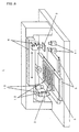
- biochips are manufactured using a biochip-manufacturing apparatus 1 as shown in Figure 1.
- a sample containing a chemical agent specifically reacting with a specimen and providing information relating to the structure and functions of the specimen is introduced into a cavity 43 via a sample charge port 46 of a discharge unit having a sample charge port 42, a cavity 43, and a sample discharge port 46 formed therein, as shown in Figure 2(a);
- a substrate 2 such as a microscope glass slide is provided at the position facing to the sample discharge port 46 , as shown in Figure 1, and the sample introduced into the cavity 43 (see Figures 2(a), 2(b)) is discharged onto a substrate 2 from the sample discharge port as droplets with a very small volume, thereby forming spots on the substrates 2;
- this process is repeated for a plurality of samples to manufacture a biochip with a plural types of spots formed from a plural types of samples being densely aligned on the substrate 2; wherein, as shown in
- the discharge head 3, the tray 4, and the first moving table 5 are separately arranged and adjusted before supplying of the sample to the substrate 2 (spotting), introducing of a sample into the discharge head 3, confirmation of discharge, correction of defective discharge points , the manner of fixing the substrate 2 to the tray 4 , the timing of fixing, storage of the substrate 2, and the like are carried out under optimal conditions separately from the first moving table 5.
- the method ensures improvement in the shape, spot position precision, and uniformity of spots formed on the substrate 2, making it possible to increase sensitivity of the resulting biochips and reduce quality dispersion.
- an embodiment of the present invention has a sample charge port 42 for charging a sample from outside the discharge unit 8, a cavity 43 for receiving and temporarily storing the sample, and a sample discharge port 46 for discharging the stored sample through a through-hole 45 in a nozzle section 44.
- the main body of the discharge unit 8 is provided with a piezoelectric/electrostrictive element 47 on the external surface thereof in a location corresponding to the location of cavity 43. Driving the piezoelectric/electro-strictive element 47 can vary the volume of the cavity 43, whereby a specific amount of the sample stored in the cavity 43 is discharged from the sample discharge port 46.
- the discharge unit main body 8 thus formed is preferably used.
- the nozzle section 44 may be formed from a nozzle plate 51 in the form of a thin plate made of PET resin, through which a sample discharge port 46 comprising of one or more through-holes 45 is provided.
- the nozzle section 44 ( through-hole 45) can usually be formed by a mechanical process such as die punching or the like.
- a resin such as PET, polyimide, or the like is used as the material for the nozzle section, laser beam machining using an excimer laser or YAG laser of a high (3 or more) dimension is preferably used.
- a beam scanning technique in which laser beams are caused to move along the cross-section configuration or a masking technique using a mask with a shape similar to the shape of the cross-section to be installed on the laser beam irradiation axis can be used.
- a masking technique which permits formation of a number of through-holes at the same time is preferred.
- a pump section 52 being composed of a spacer plate 54 in which one or more windows 53 are formed and a blockade plate 55 layered on one side of the spacer plate 54 for covering the window 53; all of them being formed from a green sheet of zirconia ceramic, and being laminated and sintered to form a discharge unit 8.
- the sample charge port 42 is provided in the blockade plate 55 and connected to an introduction hole 56 and a passage 57, both connected to the window 53 formed in a spacer plate 54.
- a piezoelectric/electrostrictive element 47 comprising a lower electrode 60, a piezoelectric/electrostrictive film 59, and an upper electrode 58 are formed on the external surface of the blockade plate 55.
- the piezoelectric/electrostrictive element 47 is deformed when an electric field is formed between the upper electrode 58 and the lower electrode 60. This decreases the volume of the cavity (a pressure chamber) 43 formed by covering the window 53, whereby a sample (a fluid containing DNA fragments and the like) filled into the cavity 43 is discharged at a predetermined rate from the sample discharge port 46 connected with the cavity 43, allowing a biochip comprising micro spots to be aligned on a substrate.
- the structure of an ink jet device similar to the type shown in Figures 2(a) and 2(b) is described in JP-A-6-40030, for example.
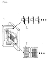
- any malfunctioning discharge unit 8 and discharge modules 7 may be replaced easily by composing the discharge head 3 with one or more discharge modules 7, and the discharge module 7 with one or more discharge units 8 as well, as shown in Figure 3(a).
- the discharge module 7 is composed of six discharge units 8 and the discharge head 3 is composed of four discharge modules 7.
- the present invention is not limited to this embodiment and it may have any number of discharge modules 7 and discharge units 8.
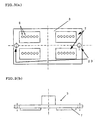
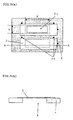
- the substrates 2 are fixed to the tray 4 using three substrate positioning pins 20, as shown in Figure 4, precise securing can be ensured without putting unnecessary loads on the substrate and without deviation of the securing positions even if such a securing operation is repeated.
- a tray 4 being composed to have 15 sheets of substrates 2 fixed thereon, as is shown in Figure 4, the present invention is not limited to this embodiment. There are no limitations to the number of substrates fixed on the tray 4.
- the tray 4 can be installed on or removed from the biochip-manufacturing apparatus 1 without causing any parts to come directly into contact with the substrates 2, whereby contamination of the substrates 2 can be effectively prevented.
- a substrate height sensor 10 may be disposed on the first moving table 5. By composing so, one may make the distance between the sample discharge port of the discharge head and the spotting surface of the substrate 2 constant, may make the speed of liquid drops reaching the surface of the substrate 2 constant, and may suppress fluctuation in the spotting area (diameter) without being influenced by the fluctuation of the thickness of the substrate 2. Thus, the spot quality is stabilized. In addition, any operational errors occurring at the time when the substrate 2 is fixed to the tray 4 may be prevented, and thus, the production yield of the biochips may be increased.
- the relative positions of the substrate 2 and the sample discharge port can be adjusted by using the first moving table 5 on which the tray 4 is placed and the second moving table 6 on which the discharge head 3 is detachably mounted.
- this embodiment is suitable as a method for manufacturing biochips for handling precious biological samples. Because the route to the point of sample discharge can be shorten, then clogging of the fluid path due to bubbles and the like can be prevented, it is possible to discharge liquid drops constantly from the discharge head 3 for a long time.
- spots comprising several different types of samples can be easily aligned on the substrate 2 at a high density by changing the types of samples sent to each discharge unit 8 of the discharge head 3 (see Figure 3(a)).
- spots of several different types of samples can be easily formed on the substrate 2 in a short period of time by composing to form spots on the substrate 2 by individually introducing each of the several different types of samples into cavities by charging it from the charging port of the corresponding discharge unit 8 (see Figure 3(a)) and discharging one of the samples introduced into the cavity as liquid droplets onto a predetermined point on a substrate 2, and repeat this operation for the several different types of samples as well.
- spot-forming speed that is, the biochip production speed since one kind of samples is discharged at same time from a plurality of discharge units 8 possessed by one discharge module 7 to form a plurality of spots at once.
- This feature is particularly effective for the manufacture of a plurality of biochips first by forming a plurality of identical spot patterns on one sheet of glass slide or the like, and then dividing the glass slide or the like. Since a plurality of discharge units 8 possessed by one discharge module 7 must discharge an equal amount of sample at the same time, such discharge units can be suitably applied to an apparatus in which the discharge conditions for each discharge unit can be conveniently adjusted as in the case of the ink jet form in the present embodiment.
- the biochip-manufacturing apparatus may comprise a plurality of discharge heads 3, wherein at least one type of sample among a plurality of samples is introduced into the cavity by being charged from the sample charge port of each discharge unit 8 (see Figure 3(a)) of each discharge head 3, one discharge head 3 into which the sample has been introduced is mounted on the second moving table 6 , the sample introduced into the cavity is discharged onto a predetermined point on the substrate 2 as liquid drops, while adjusting the relative positions of the substrate 2 and the sample discharge port of said one discharge head 3, thereby forming spots of the above-described sample on the substrate 2, then, said one discharge head 3 is removed from the second moving table 6 and another discharge head (not shown) , in which a sample of a type different from the above-mentioned sample has been introduced, is mounted on the second moving table 6 , the different type of sample introduced into the cavity is charged onto predetermined points on the substrate 2 as liquid drops, while adjusting the relative positions of the substrate 2 and the sample discharge port in a manner different from that applied to the
- a plurality of trays 4 are used and one tray 4 among the plurality of trays 4 is mounted on the first moving table 5, the sample introduced into the cavity is discharged onto predetermined points on the substrate 2 as liquid drops, while adjusting the relative positions of the substrate 2 fixed on that tray 4 and the sample discharge port, thereby forming spots of the sample provided to the discharge head 3 on one substrate 2 , then, that tray 4 is removed from the first moving table 5 and another tray (not shown) on which another substrate (not shown) is fixed is mounted on the first moving table 5, the sample introduced into the cavity is discharged onto predetermined points on another substrate (not shown) as liquid drops, while adjusting the relative positions of said other substrate (not shown) and the sample discharge port, thereby forming spots of the sample provided to the discharge head 3 on that another substrate (not shown), and the process is repeated a number of times equal to the number of the trays.
- the substrates 2 need not be directly contacted when installing or removing the tray 4, which not only prevents the substrates 2 from being contaminated, but also from being damaged even if the tray 4 is installed and removed a number of times. This is effective for processing a large amount of biochips. Also, the necessity of having a large biochip-manufacturing apparatus 1 can be avoided.
- the kinds of samples and the number of substrates may be increased independently, enabling both a large item small-scale production and a mass production.
- a sample containing necessary DNA fragments and the like is discharged onto a substrate 2 held on one tray 4, then the substrate 2 as well as the tray 4 is removed from the first moving table 5 of the biochip-manufacturing apparatus 1 and another tray on which a substrate with no spotted sample is fixed thereon is mounted on the first moving table 5 to cause the sample to be discharged.
- This operation is repeated for the number of trays meeting the required number of substrates.
- a tray reference mark 22 (see Figure 4), which is a light emitting device, is provided by forming a hole in two positions for each tray. The tray mounting position can then be confirmed and adjusted by observing and confirming these marks using a first table fixing reference 13 (see Figure 8), such as a CCD camera, above the tray.
- the discharge head 3 is removed from the second moving table 6 and another discharge head (not shown) containing another kind of DNA fragments or the like is mounted, then the spotting operation onto the substrates on the tray is repeated.
- 1,000 pieces of biochips on which 10 , 000 samples containing different DNA fragments are spotted can be prepared without producing satellites and the like.
- DNA microarrays with micro-spots having a high and constant quality can be obtained.
- This manufacturing method is particularly suitable for the manufacture of biochips which requires processing biological samples within a limited period of time.
- the spots must be formed using several discharge heads.
- This embodiment is effective in such a case.
- the above configuration using robots can be materialized by independently providing a discharge head 3, a tray 4, a first moving table 5 , and a second moving table 6 as shown in Figure 1.
- the production speed and the productivity for a large number of biochips may be improved, by employing said composition. More specifically, because it is possible to perform spotting on a number of substrates using a plurality of trays by the application of a first robot until the entire amount of the sample introduced into one discharge head has been consumed, while performing an additional spotting operation onto the substrate on which the spotting has been completed using the first robot by the application of a second robot, precious samples can be utilized effectively and mass-production of biochips is possible.
- the unit of this embodiment can be configured so that the position of the discharge head 3 in the absolute coordinates of the second moving table 6 is measured each time the discharge head 3 is mounted on the second moving table 6 and the position of the tray 4 in the absolute coordinates of the first moving table 5 is measured each time the tray 4 is mounted on the first moving table 5, as shown in Figure 8.
- the relative positions of the discharge head 3 and the tray 4 is calculated from the measured results so that the spots may be formed by discharging the sample onto predetermined points on the substrates 2 fixed on the tray 4.
- One may decrease deviation of the mounting position of the discharge head 3 and deviation of the mounting position of the tray 4, whereby positional accuracy of spots on the substrate may be improved, by thus composing as mentioned.
- the discharge head 3 is formed with a head reference mark 23 of a light-emitting device, as shown in Figure 3(a).
- a second table fixing reference 11 such as a CCD camera provided in a specified location under the discharge head 3 to prevent deviation of spotting positions due to misalignment of the discharge head 3 when the discharge head is replaced.
- direct observation of lights from a light-emitting device such as a CCD camera in this manner ensures observation unaffected by the surface conditions of the reflection body and excludes influence of disturbing external lights. Positioning accuracy can be improved in this manner. One may achieve to keep the deviation in the positions of ultimately produced spots within 50 ⁇ m of the designed value.
- Light emitting devices such as a photodiode can be used for forming such a reference mark. It is possible, however, to employ a method of observation comprising providing a hole and introducing lights through a separate fiber or prism.
- the positional deviations of the discharge head 3 and the tray 4 can be decreased even more by repeating the position measurement of the discharge head 3 with respect to the absolute coordinates of the second moving table 6 and the position measurement of the tray 4 with respect to the absolute coordinates of the first moving table 5 for an optional number of times, thereby correcting relative positions of the discharge head 3 and the tray 4.
- the positional accuracy can be further improved in this manner. For example, if spotting onto one tray 4 is carried out by correcting the positional deviation of the discharge head 3 each time the tray 4 is mounted on the first moving table, any minor positioning deviations of the discharge head 3 occurring as a result of a move of the discharge head 3 can be corrected each time the tray 4 is replaced.
- a head reference mark 23 in at least two predetermined locations of the discharge head 3 (see Figure 3(a)) and a second table fixing reference 11 such as a CCD camera at two or more locations of an immovable part of the second moving table, measure the relative positions of the head reference mark 23 and second table fixing reference 11 at two or more locations, and apply the measured results to the correction of the mounting position deviation of the discharge head 3 by decomposing the direction and amount of the deviation in the longitudinal, lateral, and rotational directions.
- a second table fixing reference 11 such as a CCD camera
- the positional precision improves by measuring the positions at two and more points in this manner.
- calculation and correction become easy by offsetting in each of the directions to which the second moving table 6 moves.
- the table reference mark 12 is provided at least at two points in the movable part of the first moving table 5 and the first table fixing reference 13 such as a CCD camera is provided at least at two points in the immovable part of the first moving table 5, to measure the relative positions of the table reference mark 12 and first table fixing reference 13 at least at two points ;
- the tray reference mark 22 (see Figure 4) is provided by forming a hole in at least two positions of the tray 4 to measure the relative positions of the tray reference mark 22 and the first table fixing reference 13 at two or more locations; and based on the measured results obtained, the direction and amount of deviation of the mounting position of the tray 4 are corrected by decomposing the deviation in the longitudinal and lateral directions.
- the deviation of the mounting position of the tray 4 with respect to the movable part of the first moving table 5 can be corrected by comparing the table reference mark 12 provided in the movable part of the first moving table 5 to the first table fixing reference 13 provided in the immovable part of the first moving table 5, and comparing the tray reference mark 22 (see Figure 4) provided by forming a hole at a predetermined point of the tray 4 to the first table fixing reference 13. Therefore, the necessity of proving a first table fixing reference 13 such as a CCD camera in the movable part of the first moving table 5, of which the reference itself easily deviates, can be avoided.
- the correction not affected by the corrections of the positional deviation of the tray 4 with respect to the movable part of the first moving table 5, is possible. More accurate correction is possible in this manner. One may improve the positional precision, by comparing these positions at two and more points.
- correction can be carried out easily by offsetting in each of the directions to which the first moving table 5 moves.
- At least one of the first moving table 5 or the second moving table 6 can be moved while correcting using an outside reference 14 provided in the immovable part of at least one of the first moving table 5 or the second moving table 6.
- the absolute precision for the movement of the first moving table 5 or the second moving table 6 can be also increased by combining the above-mentioned correction of positional deviation for the discharge head 3 and the tray 4. In this manner, the positional precision for the spot arrangement can be further improved, resulting in further improvement of the biochip quality.
- the above-mentioned correction of the positional deviation for the discharge head 3 and tray 4 is performed based on the comparison between the head reference mark 23 (see Figure 3(a)) and the second table fixing reference 11 (see Figure 8), the comparison between the table reference mark 12 (see Figure 8) and the first table fixing reference 13 (see Figure 8), and the comparison between the tray reference mark 22 (see Figure 4) and the first table fixing reference 13 (see Figure 8), and by calculating the positional relationship of these elements.
- the outside reference 14 is preferably a reference gauge composed of a material with a low thermal expansion coefficient .
- the spot-positioning accuracy is increased since the effect of temperature variations, change of properties with time, and change in the XY orbit resistance may be kept in a lower level by composing so.
- the first moving table 5 and the second moving table 6 must be continuously operated for such a long time that movable parts of these tables are heated, causing their parts and components to swell. As a result, the positional accuracy of the trays 4 and discharge heads 3 mounted on these tables is impaired.
- the first moving table 5 and the second moving table 6 be moved while adjusting the relative positions of the substrate 2 and the sample discharge port so that the discharge head 3 and the tray 4 are brought to predetermined positions, and then the sample be discharged from the sample discharge port to form spots in the state in which the discharge head 3 and the tray 4 stop.
- the tray 4 is moved to have a predetermined positional relationship with the discharge head 3, while simultaneously adjusting the relative positions of the sample discharge ports for all discharge units 8 in one discharge module 7 and one substrate 2a among a plurality of substrates 2 fixed on the tray 4; the sample stored in one discharge module 7a is discharged onto one substrate 2a from the sample discharge ports for all discharge units 8a in said one discharge module 7a, thereby forming spots corresponding to the sample discharge ports for all discharge units 8a in said one discharge module 7a; next, the tray 4 is moved to establish a predetermined positional relationship between one substrate 2a and the sample discharge ports of all discharge units 8b in another discharge module 7b, while simultaneously adjusting the relative positional relationship between the substrate 2a and the sample discharge ports of all discharge units 8b in said other discharge module 7b, the sample stored in said other discharge module
- the sample can be discharged simultaneously from all discharge units 8 in the discharge module 7 by implementing the operations of movement, position adjustment, and spotting on one sheet of substrate 2 for each discharge module 7. Therefore, spotting speed is increased.
- the positioning accuracy of each discharge unit 8 in the discharge module 7 is previously increased by a mechanical means, it is possible to simultaneously align a plurality of discharge units 8 on a discharge module 7. The spotting speed and the positioning accuracy in the entire process can be improved in this manner.
- one discharge head 3 is composed of a plurality of discharge modules 7 , the number of discharge units 8 per one discharge head 3 can be increased.
- the method can easily handle an increased number of samples. Using this configuration, it is possible not only to increase the number of discharge units 8 in one discharge head 3 by increasing the number of discharge modules 7 without increasing the density of the discharge units 8 themselves, but also to increase the types of samples which are processed in one discharge head 3. The production efficiency is improved in this manner.
- the tray 4 is moved to establish a predetermined positional relationship between the one substrate 2a and the sample discharge ports of all discharge units 8b in other discharge modules 7b, while simultaneously adjusting the relative positional relationship between the substrate 2a and the sample discharge ports of all discharge units 8b in those other discharge modules 7b; and after forming spots on said one substrate 2a using the sample from the sample discharge ports for all discharge units 8 in the discharge head 3, when the tray 4 is moved to establish a predetermined positional relationship between the other substrate 2b and all sample discharge ports of the other discharge units in other discharge modules for forming spots on that other substrate 2b, while adjusting the relative positional relationship between the substrate 2b and the sample discharge ports of all discharge units 8a in those other discharge modules 7a, the discharge head 3 is preferably maintained stopped.
- the relative positions of the tray 4 and the discharge head 3 can be preferably changed by securing the discharge head 3 in the XY directions on the plane and moving the tray 4 on which the substrates are fixed, as shown in Figure 17.
- the movement of the discharge head results in subjecting the fixed discharge unit 8 (see Figure 3(a)) to external disturbances such as vibration, airflow, and the like.
- Such external disturbances may change the state of the liquid surface at the discharge port of the discharge unit 8 (see Figure 3(a)), which may give rise to fluctuation in the amount and direction of discharge of liquid drops.
- the fluid sample may become dry and cause discharge malfunction.
- Discharge of samples while the discharge head 3 is moving brings about many disadvantages in accurately controlling spotting positions. This is because the discharged fluid droplets are provided with a velocity in the XY direction corresponding to the moving speed of the discharge head 3 at the time of discharge, which may affect the point on the glass slide which the spot reaches. Therefore, a preferable method is to discharge the sample and produce spots when the discharge head 3 and tray 4 are brought to desired relative positions in the XY direction by moving the tray 4.
- Fixing the location of the discharge head 3 in the XY direction while changing the position relative to the tray 4 is desirable in securing consistent emission of discharge signals because cables delivering signals to the discharge head 3 are not affected by vibration and the like if the discharge head 3 is fixed in a fixed position, thereby suppressing changes in the cable characteristics such as impedance due to twisting. Consequently, consistent discharge of drops, specifically, quality improvement of the DNA microarray, can be achieved. It is possible to move the discharge head 3 in the vertical direction (Z direction) with respect to the tray 4 and reduce the distance between the sample discharge port of the discharge unit 8 (see Figure 3(a)) and the substrate 2 (see Figure 1), i.e. the distance in the Z direction vertical to substrate 2, only at the moment of discharge.
- the discharged liquid drops are prevented from being damaged, by composing so, even if foreign substance is attached to the substrate 2 (see Figure 1) and the discharge head 3.
- the effect of the curved discharge direction when liquid droplets are discharged from the discharge unit on the spot-forming points can be reduced by shortening the distance between the substrate 2 (see Figure 1) and the discharge head 3.
- the degree of spot-forming point deviation can be reduced in this manner.
- the sample is preferably discharged from the discharge units at regular intervals merely for the purpose of dummy discharge during the time other than the period in which a series of operations for forming spots on specified points on substrates by discharging samples from the sample discharge ports takes place.
- the intervals of the dummy discharge is preferably almost the same as the intervals of the sample discharge, beginning from before the time when a series of operations is started for forming spots on specified points on substrates by discharging samples from the sample discharge ports.
- drying conditions of the samples waiting for discharge near the sample discharge ports as well as the moving conditions of the sample before discharge become constant, accordingly, sample properties at the time of discharge become equal. This stabilizes the discharge direction, stabilizes the state of discharged liquid droplets, and produces spots with a uniform shape on the substrate 2.
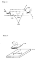
- the substrate 2 is irradiated with a coaxial light 30, converged using a lens 31 as shown in Figure 14.
- a spot configuration is determined by the image produced by reflection of light on the surface of the substrate 2 on which spots have been formed, thereby accumulating propriety information for the spots.
- the substrate 2 fixed on the tray 4 is irradiated with a coaxial light 30 emitted from the side and reflected by a half mirror 32 and a photograph is taken from the top by a CCD camera.
- the configuration is not limited to that shown in Figure 14. Any system capable of taking images on the substrate 2 on which spots have been formed may be applied.
- Such a system makes it possible to view the shape of spots made from a transparent liquid sample such as a DNA solution as a shadow produced by the difference of light reflection angles at the edges of the spots. Since the spot quality can be easily determined using this system, a substrate 2 with a defective spot can be easily excluded, whereby the biochip quality can be improved.
- the substrate 2 may be fixed to a tray 4 by means of adhesion using adhesive tape, silicone rubber, etc., or fixed by suction, for example by using vacuum suction
- a more preferable method is a mechanical securing method using board springs 102 and pins 103 as shown in Figure 15. This method ensures accurate securing by a simple means without causing adhesive residues to be attached to the substrate 2 and without enlarging the scale of facilities for the tray 4.
- the positions, number, and the like of the pins 103 and board springs 102 to secure the substrate 2 are appropriately determined according to the slipping properties of the tray 4 and substrate 2, strength of the board springs 102, thickness of the substrate 2, and other factors. Securing the substrate 2 using three pins 103 as shown in Figures 15 and 16 is desirable in view of precision.
- the tray 4 may be previously provided with an opening 104 for ease of attachment and removal of the substrates 2 in locations wherein the substrates 2 are placed.
- the area 105 on the surface of the tray corresponding to the part of the substrate 2 on which spots are formed is made hollow and linked to the bottom surface of the tray 4.
- This structure makes a light tray 4 and increases the biochip production efficiency.
- the structure is advantageous for maintaining and improving quality of the biochips because such a structure enables the manner by which spots are formed to be observed inline from the bottom surface of the tray 4 through the hollow space.
- the configuration having a hollow space has the merit of absence of any light reflection on the tray surface. The measurement is easier.
- the hollow space may be cut concave and, to exhibit the above advantage, preferably has a bottom surface processed so as not to reflect light.
- the operation of densely aligning and fixing droplets with a minute volume on a predetermined substrate can be performed with increased precision, thereby shortening the time required for the micro spot-forming operation.
- An increased spot positioning accuracy and spot density can reduce the area for the spots. Therefore, the effect of fluctuations of a coating used for immobilizing DNA samples on a substrate on the spotting operation can be reduced, leading to improved biochip quality.
- the amount of expensive reagent, such as a hybrid fluid, used for inspecting DNA samples contained in the spotting liquid (the sample) can be reduced.
- Biochips were prepared using a biochip-manufacturing apparatus 1 shown in Figure 1 on which a discharge head 3 of Figure 3(a) and a tray 4 of Figure 4 are mounted.
- the tray 4 was previously provided with an opening 104 for ease of attachment and removal of the substrates 2 in locations wherein the substrates 2 are placed, and has a hollow space on the surface 105 of the tray in the area corresponding to the substrate 2 on which spots are formed, wherein the hollow space goes through the bottom of the tray 4, as shown in Figures 15 and 16.
- the tray 4 and discharge head 3 are detachably mounted on the biochip-manufacturing apparatus 1.
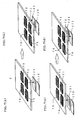
- the samples were discharged in the following manner. Specifically, the samples were discharged from the discharge module 71 of the discharge head 3 after moving the substrate 121 as shown in Figure 7(a). Then, the substrate 121 was moved as shown in Figure 7(b) and the samples were discharged from the discharge module 72 of the discharge head 3 to locations different from the locations in which the samples had been discharged by the discharge module 71. In the same manner, the substrate 121 was moved and the samples were discharged from the discharge module 73 of the discharge head 3 to locations different from the locations in which the samples had been discharged by the discharge modules 71 and 72.
- the subs trate 121 was moved as shown in Figure 7(c), and the samples were discharged from the discharge module 74 of the discharge head 3 to locations different from the locations in which the samples had been discharged by the discharge modules 71, 72, and 73. Spots were formed by repeating the operation of discharging samples from the discharge module 71 onto the substrate 122, as shown in Figure 7(d).
- Biochips were prepared using a biochip-manufacturing apparatus 1 shown in Figure 8.
- Samples were charged to the discharge units of each discharge head 3, which was installed on the second moving table 6, and the tray 4 was installed on the first moving table 5.
- the amount of correction was calculated by comparing the relative positions of each reference mark and each reference, and the table movement taking into account the amount of correction was repeated.
- Biochips were manufactured while measuring deviations of installation of each head and tray, each time these were installed, by comparing the head reference marks 23 (see Figure 3(a)) to the tray reference marks 22 (see Figure 4) and by comparing the first table fixing reference 13 and the second table fixing reference 11. 300 pieces of biochips with a spot positioning precision of ⁇ 20 ⁇ m were manufactured within 24 hours without unstable sample discharge.
- Biochips were manufactured using the biochip-manufacturing apparatus 1 shown in Figure 9, wherein the above-described process was employed.
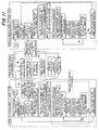
- the manufacturing procedure when one biochip-manufacturing apparatus 1 was used is shown in the flowchart of Figure 10, and that using two biochip-manufacturing apparatus 1 is shown in the flowchart 11.
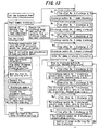
- Figure 12 is a part of the flowchart shown in Figures 10 and 11 showing details of an area for carrying out correction of a moving amount of the first moving table 5 during movement in the XYZ directions using an outside reference 14.
- Figure 13 is a part of the flowchart shown in Figures 10 and 11 showing details of discharge timing which is controlled for each discharge module 7 (see Figure 3(a)).
- dummy discharge was performed at regular intervals, excluding the period during which the samples were discharged onto substrates.
- the interval T for dummy discharge is specified by the dummy discharge parameter T1 shown in the discharge timing flow shown in Figure 13.
- dummy discharge was also carried out for each module as in the case of sample spotting onto the substrates.
- a constant dummy discharge interval was maintained by employing the same parameters T1 to T4.
- the same T5-T8 parameters were used to ensure stable spotting quality.
- the means for correcting deviation of the mounting position was used for removing and installing the discharge head and tray in the same manner as in Example 2.
- the moving amount of the first moving table was corrected using the outside reference shown in Figure 12.
- the resulting spot configuration was inspected using the instrument shown in Figure 14. As a result , in the spotting operation of a sample containing a chemical agent specifically reacting with a transparent sample and providing information relating to the structure and functions of the specimen, the spot configuration was clearly observed and the data concerning the spot positions and shapes was acquired and accumulated.
- the operation of densely aligning and fixing droplets with a minute volume on a predetermined substrate can be performed by using the method of the present invention with increased precision, thereby shortening the time required for the micro spot-forming operation.
Landscapes
- Chemical & Material Sciences (AREA)
- Engineering & Computer Science (AREA)
- Organic Chemistry (AREA)
- Nanotechnology (AREA)
- Condensed Matter Physics & Semiconductors (AREA)
- Composite Materials (AREA)
- Physics & Mathematics (AREA)
- General Physics & Mathematics (AREA)
- Materials Engineering (AREA)
- Crystallography & Structural Chemistry (AREA)
- Chemical Kinetics & Catalysis (AREA)
- Automatic Analysis And Handling Materials Therefor (AREA)
- Sampling And Sample Adjustment (AREA)
Abstract
Description
Claims (21)
- A method for manufacturing a biochip with spots of plural kinds of samples densely aligned on a substrate, wherein a sample containing a reagent specifically reactive with a specimen and providing information relating to the structure and functions of the specimen is introduced into a cavity via a sample charge port of a discharge unit having a sample charge port, a cavity, and a sample discharge port formed thereon, a substrate is provided at the position facing to the sample discharge port, the sample having been introduced into the cavity is discharged onto the substrate from the sample discharge port as droplets with a very small volume, thereby forming spots on the substrate, and the process is repeated for a plural kinds of the above-mentioned samples;
said biochip manufacturing method is characterized by;
providing a discharge head equipped with one or more discharge modules each of which being formed from one or more discharge units,
introducing at least one of said plural kinds of samples into a cavity from a sample charge port of the discharge unit in a discharge head, so that one discharge unit is provided with only one kind of sample,
transferring a first moving table, on which one or more trays with one or more substrates fixed thereon are detachably mounted, to a sample discharge point of the discharge unit corresponding to a predetermined point on the substrate, and
discharging the sample having been introduced into the cavity from the sample discharge port to a predetermined point on the substrate as liquid droplets, thereby spots of plural kinds of samples are densely aligned on the substrate. - The biochip manufacturing method according to claim 1, wherein the first moving table on which the tray being placed and a second moving table on which the discharge head being detachably mounted are provided, and the relative position of the substrate and the sample discharge port is adjusted.
- The biochip manufacturing method according to claim 1 or 2, wherein each of said plural kinds of samples is individually introduced into the cavity by charging it from the charging port of the corresponding discharge unit, and one of the samples introduced into the cavity is discharged as liquid droplets onto a predetermined point on the substrate, thereby forming spots on the substrate, and this process is repeated for the plural kinds of samples.
- The biochip manufacturing method according to claim 1 or 2 , wherein at least one sample among said plural kinds of samples is introduced into the cavity by charging it from the charging port of the discharge unit of the discharge head so that only one kind of sample is provided to one discharge module, and said one sample introduced into the cavity is discharged as liquid droplets onto a predetermined point on the substrate, thereby forming spots on the substrate, and this process is repeated for the above plural number of samples.
- The biochip manufacturing method according to claim 2, which comprises,
provide two or more discharge heads,
introducing at least one sample among said plural kinds of samples into the cavity by charging it from the sample charge port of each discharge unit of each discharge head,
mounting one discharge head into which the sample has been introduced on the second moving table,
discharging the sample having been introduced into the cavity onto the predetermined point on the substrate as liquid drops, with adjusting the relative position of the substrate and the sample discharge port of said one discharge head, thereby forming spots of the sample on one substrate,
removing said one discharge head from the second moving table,
mounting another discharge head into which a sample different from said sample has been introduced on the second moving table,
discharging this different sample having been introduced into the cavity onto the predetermined point on the substrate as liquid drops, with adjusting the relative position of the substrate and the sample discharge port of said one discharge head, thereby forming spots of the sample on one substrate, and
repeating the process a plural number of times equal to the number of discharge heads. - The biochip manufacturing method according to claim 2, which comprises,
providing plural number of trays,
mounting one tray among the plural number of trays on the first moving table,
discharging the sample having been introduced into the cavity onto the predetermined point on the substrate as liquid drops, with adjusting the relative position of the substrate fixed to said one tray and the sample discharge port, thereby forming spots of the sample on one substrate,
removing said one tray from the first moving table,
mounting another tray to which the other substrate is fixed on the first moving table,
discharging each sample having been introduced into the cavity onto the predetermined point on the substrate as liquid drops, with adjusting the relative position of the other substrate and the sample discharge port, thereby forming spots of the sample on one substrate, and
repeating the process a number of times equal to the number of the trays. - The biochip manufacturing method according to claim 2, which comprises,
providing plural number of robots each of which is composed of said first moving table and second moving table,
mounting tray on which the substrate is fixed on the first moving table forming one robot among said plural number of robots,
discharging the sample provided to one discharge head mounted on said second moving table is d onto the predetermined point on the substrate as liquid drops, with adjusting the relative positions of the substrate and the sample discharge port, thereby forming spots of the sample provided to one discharge head on the substrate,
removing said one tray,
mounting the removed tray on one first moving table forming other robot among said plural number of robots,
discharging the sample provided to the other discharge head on the one second moving table composing said other robot onto the predetermined point on the substrate as liquid drops, thereby forming spots of the sample on one substrate, and
repeating the process a number of times equal to the number of the robots. - The biochip manufacturing method according to claim 7, wherein spots are formed on another substrate with said one robot using another tray on which said another substrate is fixed, during a period that spots are formed on said one substrate by using said another robot after forming spots on said one substrate using said one robot.
- The biochip manufacturing method according to claim 2, which comprises,
carrying at least one of two operations out , wherein one operation is measuring the position of said discharge head with respect to the absolute coordinates of said second moving table, which is performed each time the discharge head is mounted on the second moving table, and another operation is measuring the position of said tray with respect to the absolute coordinates of said first moving table, which is performed each time the tray is mounted on the fist moving table,
calculating the relative positional relationship of the said discharge head and the said tray based on the measured results, and
discharging the sample onto the predetermined point on the said substrate fixed on the said tray to form spots. - The biochip manufacturing method according to claim 9, wherein positional deviation of the discharge head and the tray is corrected by repeating the position measurement of the discharge head with respect to the absolute coordinates of the second moving table and the position measurement of the tray with respect to the absolute coordinates of the first moving table for an optional number of times.
- The biochip manufacturing method according to claim 9, which comprises,
providing the discharge head with head reference marks in at least two predetermined locations,
providing the second moving table with second table fixing references at two or more locations of the immovable part thereof,
measuring the relative positions of the head reference marks and the second table fixing references at two or more locations, and
based on the measured results obtained, correcting the direction and amount of deviation of the mounting position of the head by decomposing the deviation in the longitudinal, lateral, and rotational directions. - The biochip manufacturing method according to claim 11, which comprises,
providing the first moving table with the table reference marks at two or more locations on the movable part thereof and first table fixing reference marks at two or more locations on the immovable part thereof,
measuring the relative positions of the head reference mark and the first table fixing references at two or more locations,
providing the tray with the tray reference marks in at least two predetermined locations of the tray,
measuring the relative positions of the tray reference marks and the first table fixing references at two or more locations, and
correcting the direction and amount of deviation of the mounting position of the tray by decomposing the deviation in the longitudinal and lateral directions , based on the measured results obtained. - The biochip manufacturing method according to claim 2, wherein at least one of the first moving table and the second moving table is moved while correcting by using an outside reference fixed in the immovable part of at least one of the first moving table and the second moving table.
- The biochip manufacturing method according to claim 13, wherein said outside reference is made from a material with a low thermal expansion coefficient.
- The biochip manufacturing method according to claim 2, which comprises,
moving the first moving table and the second moving table while adjusting the relative position of the substrate and the sample discharge port so that the discharge head and the tray are brought to predetermined positions, and
discharging the sample from the sample discharge port to form spots in the state in which the discharge head and the tray are in stationary conditions. - The biochip manufacturing method according to claim 2, which comprises,
providing a discharge head equipped with two or more discharge modules,
providing a tray equipped with two or more substrates fixed thereon,
moving the tray to have a predetermined positional relationship between the sample discharge ports of all discharge units in one discharge module and one substrate among the two or more substrates fixed on the tray, while simultaneously adjusting the relative positions of the sample discharge ports for all discharge units in one discharge module and one substrate among the two or more substrates fixed on the tray,
discharging the sample having been stored in said one discharge module onto said one substrate from the sample discharge ports for all discharge units in said one discharge module,
thereby forming spots corresponding to the sample discharge ports for all discharge units in said one discharge module,
and, moving the tray to establish a predetermined positional relationship between said one substrate and the sample discharge ports of all discharge units in another discharge module, while simultaneously adjusting the relative positional relationship between the substrate and the sample discharge ports of all discharge units in said another discharge module,
discharging the sample stored in said another discharge module onto said one substrate from the sample discharge ports for all discharge units in said another discharge module,
thereby forming spots corresponding to the sample discharge ports for all discharge units in said another discharge module,
repeating this process for a number of times equal to the number of discharge modules arranged in said discharge head,
thereby forming spots on said one substrate corresponding to the sample discharge ports for all discharge units present in the discharge head,
and moving the tray to secure another substrate on the tray,
thereby forming spots corresponding to sample discharge ports for all discharge units present in the discharge head,
repeating this process for a number of times equal to the number of substrates fixed on the tray, and
with maintaining intervals of sample discharge operations from said discharge units in said two or more discharge modules almost the same. - The biochip manufacturing method according to claim 16, which comprises,
discharging the sample having been stored in said one discharge module onto said one substrate from the sample discharge ports for all discharge units in said one discharge module, thereby forming spots, and
moving the tray with the discharge head being in stationary conditions to establish a predetermined positional relationship between one substrate and the sample discharge ports of all discharge units in another discharge module, while simultaneously adjusting the relative positional relationship between the substrate and the sample discharge ports of all discharge units in said another discharge module,
after forming spots on said one substrate corresponding to the sample discharge ports for all discharge units present in the discharge head, and
moving the tray with the discharge head being in stationary conditions to establish a predetermined positional relationship between said another substrate and said sample discharge ports of all other discharge units in said another discharge module, while adjusting the relative positional relationship between the substrate and the sample discharge ports of all discharge units in said another discharge module. - The biochip manufacturing method according to claim 17, wherein the discharge head is vertically removed from the tray before moving the tray, and after moving the tray, the discharge head is vertically moved to approach the tray.
- The biochip manufacturing method according to claim 2, wherein the sample is discharged from the discharge units at regular intervals merely for the purpose of dummy discharge during the time other than the period in which a series of operations for forming spots on predetermined points on substrates by discharging samples from the sample discharge ports are performed.
- The biochip manufacturing method according to claim 19, wherein the intervals of the dummy discharge become almost the same as the intervals of the sample discharge, beginning from before the time when the series of operations is started for forming spots on predetermined points on substrates by discharging samples from the sample discharge ports.
- The biochip manufacturing method according to claim 20, wherein the upper surface of the substrate is irradiated with a coaxial light after forming spots on predetermined points of the substrate by discharging the samples from said sample discharge ports, and a spot configuration is measured by the image produced by ref lection of light on the surface of the substrate on which spots have been formed, thereby accumulating propriety information about the spots.
Applications Claiming Priority (3)
| Application Number | Priority Date | Filing Date | Title |
|---|---|---|---|
| JP2001134719 | 2001-05-01 | ||
| JP2001134719A JP2002196010A (en) | 2000-10-16 | 2001-05-01 | Micropipette, dispensing device and method for producing biochip |
| PCT/JP2002/004312 WO2002090984A1 (en) | 2001-05-01 | 2002-04-30 | Method for making biochip |
Publications (3)
| Publication Number | Publication Date |
|---|---|
| EP1385000A1 true EP1385000A1 (en) | 2004-01-28 |
| EP1385000A4 EP1385000A4 (en) | 2006-04-19 |
| EP1385000B1 EP1385000B1 (en) | 2007-11-21 |
Family
ID=18982350
Family Applications (1)
| Application Number | Title | Priority Date | Filing Date |
|---|---|---|---|
| EP02722893A Expired - Lifetime EP1385000B1 (en) | 2001-05-01 | 2002-04-30 | Method for making biochip |
Country Status (5)
| Country | Link |
|---|---|
| US (1) | US7160512B2 (en) |
| EP (1) | EP1385000B1 (en) |
| JP (1) | JP3927125B2 (en) |
| DE (1) | DE60223667T2 (en) |
| WO (1) | WO2002090984A1 (en) |
Families Citing this family (24)
| Publication number | Priority date | Publication date | Assignee | Title |
|---|---|---|---|---|
| US6063339A (en) * | 1998-01-09 | 2000-05-16 | Cartesian Technologies, Inc. | Method and apparatus for high-speed dot array dispensing |
| EP1722236A1 (en) * | 1999-02-16 | 2006-11-15 | Applera Corporation | Bead dispensing system |
| US20020106308A1 (en) * | 2001-02-02 | 2002-08-08 | Zweifel Ronald A. | Microdrop dispensing apparatus |
| US7314595B2 (en) * | 2001-05-03 | 2008-01-01 | Affymetrix, Inc. | High throughput microarray spotting system and method |
| JP2003149255A (en) * | 2001-11-15 | 2003-05-21 | Toyobo Co Ltd | Dispensing device that can move to rectangular coordinates and cylindrical coordinates |
| US7467928B2 (en) * | 2002-12-12 | 2008-12-23 | Board Of Trustees Of The University Of Arkansas | Microfluidic device utilizing magnetohydrodynamics and method for fabrication thereof |
| GB0303861D0 (en) * | 2003-02-20 | 2003-03-26 | Arrayjet Ltd | Improved printing method and apparatus |
| KR100540633B1 (en) * | 2003-06-20 | 2006-01-11 | 주식회사 탑 엔지니어링 | Paste applicator and its control method |
| JP4441336B2 (en) * | 2004-06-11 | 2010-03-31 | 日本碍子株式会社 | Manufacturing method of microarray |
| EP1782075B1 (en) * | 2004-08-04 | 2023-10-04 | Life Technologies Corporation | Method for differentially coating a substrate |
| US20060105453A1 (en) | 2004-09-09 | 2006-05-18 | Brenan Colin J | Coating process for microfluidic sample arrays |
| US12070731B2 (en) | 2004-08-04 | 2024-08-27 | Life Technologies Corporation | Methods and systems for aligning dispensing arrays with microfluidic sample arrays |
| WO2006123538A1 (en) * | 2005-05-17 | 2006-11-23 | Kyocera Corporation | Spot pin, spot device, method for spot deposition of liquid, and method of manufacturing unit for biochemical analysis |
| JP2007057318A (en) * | 2005-08-23 | 2007-03-08 | Olympus Corp | Analyzer, feeder, stirring device and stirring method |
| KR100738087B1 (en) * | 2005-12-22 | 2007-07-12 | 삼성전자주식회사 | Cell quantitative distribution device using droplet manipulation |
| US7810698B2 (en) * | 2008-11-20 | 2010-10-12 | Asm Assembly Automation Ltd. | Vision system for positioning a bonding tool |
| KR101065977B1 (en) * | 2008-12-18 | 2011-09-19 | 삼성에스디아이 주식회사 | Ink jet printer head alignment method and device therefor |
| US20100248981A1 (en) * | 2009-03-27 | 2010-09-30 | Affymetrix, Inc. | System and methods for processing microarrays |
| JP2014119387A (en) * | 2012-12-18 | 2014-06-30 | Sony Corp | Dispensing apparatus, analyzer and method for controlling dispensing apparatus |
| JP6002061B2 (en) | 2013-02-27 | 2016-10-05 | 株式会社日立製作所 | Particle analyzer |
| JP6805028B2 (en) * | 2017-03-07 | 2020-12-23 | 東京エレクトロン株式会社 | Droplet ejection device, droplet ejection method, program and computer storage medium |
| JP6925909B2 (en) | 2017-08-22 | 2021-08-25 | 東芝テック株式会社 | Drug droplet drop device and drug solution discharge device |
| GB2566112B (en) * | 2017-09-05 | 2022-10-12 | Arrayjet Ltd | Method and device for producing printed microarrays |
| KR102581395B1 (en) * | 2022-10-26 | 2023-09-21 | 주식회사 큐리오시스 | Apparatus and method for checking normal mounting of slide tray |
Family Cites Families (20)
| Publication number | Priority date | Publication date | Assignee | Title |
|---|---|---|---|---|
| JPS59178258A (en) | 1983-03-28 | 1984-10-09 | Fujitsu Ltd | Ink-jet recording head |
| JP2714172B2 (en) | 1989-09-18 | 1998-02-16 | キヤノン株式会社 | Ink jet head, ink jet cartridge having the head, and ink jet recording apparatus having the cartridge |
| JP3177608B2 (en) * | 1992-02-20 | 2001-06-18 | 株式会社ニチリョー | Automatic dispensing device |
| JP3144948B2 (en) | 1992-05-27 | 2001-03-12 | 日本碍子株式会社 | Inkjet print head |
| JPH08233710A (en) * | 1995-02-24 | 1996-09-13 | Hitachi Ltd | Sample preparation device |
| US5958342A (en) * | 1996-05-17 | 1999-09-28 | Incyte Pharmaceuticals, Inc. | Jet droplet device |
| JP4208392B2 (en) * | 1997-08-01 | 2009-01-14 | キヤノン株式会社 | Liquid composition for ejecting probe by inkjet method |
| US5882930A (en) * | 1997-11-10 | 1999-03-16 | Hyseq, Inc. | Reagent transfer device |
| US6102984A (en) * | 1998-11-09 | 2000-08-15 | Packard Bioscience Company | Apparatus for moving fluids between microplates utilizing two plate transport mechanisms |
| JP3299212B2 (en) * | 1999-02-03 | 2002-07-08 | 株式会社カケンジェネックス | Liquid transfer member and transfer device |
| US6242266B1 (en) * | 1999-04-30 | 2001-06-05 | Agilent Technologies Inc. | Preparation of biopolymer arrays |
| GB2354841B (en) * | 1999-10-01 | 2002-07-24 | Gpc Ag | Pick and place robot system |
| US6232072B1 (en) * | 1999-10-15 | 2001-05-15 | Agilent Technologies, Inc. | Biopolymer array inspection |
| JP2001116750A (en) * | 1999-10-21 | 2001-04-27 | Ngk Insulators Ltd | Method for producing reactive chip, reactive chip that can be produced by the method, and reactive substance |
| JP3647370B2 (en) * | 1999-10-22 | 2005-05-11 | 日本碍子株式会社 | Dispensing apparatus and DNA chip manufacturing method |
| JP2001186881A (en) | 1999-10-22 | 2001-07-10 | Ngk Insulators Ltd | Method for producing DNA chip |
| EP1716925B1 (en) * | 1999-10-22 | 2008-12-24 | Ngk Insulators, Ltd. | Dispenser and method for producing DNA chip |
| US6656432B1 (en) * | 1999-10-22 | 2003-12-02 | Ngk Insulators, Ltd. | Micropipette and dividedly injectable apparatus |
| EP1094318B1 (en) * | 1999-10-22 | 2007-03-28 | Ngk Insulators, Ltd. | DNA chip and method for producing the same |
| US6474566B1 (en) * | 2000-06-20 | 2002-11-05 | Ngk Insulators, Ltd. | Drop discharge device |
-
2002
- 2002-04-30 US US10/135,200 patent/US7160512B2/en not_active Expired - Fee Related
- 2002-04-30 DE DE60223667T patent/DE60223667T2/en not_active Expired - Lifetime
- 2002-04-30 JP JP2002588190A patent/JP3927125B2/en not_active Expired - Fee Related
- 2002-04-30 EP EP02722893A patent/EP1385000B1/en not_active Expired - Lifetime
- 2002-04-30 WO PCT/JP2002/004312 patent/WO2002090984A1/en not_active Ceased
Also Published As
| Publication number | Publication date |
|---|---|
| JPWO2002090984A1 (en) | 2004-08-26 |
| DE60223667D1 (en) | 2008-01-03 |
| DE60223667T2 (en) | 2009-01-02 |
| US20030012698A1 (en) | 2003-01-16 |
| WO2002090984A1 (en) | 2002-11-14 |
| EP1385000A4 (en) | 2006-04-19 |
| JP3927125B2 (en) | 2007-06-06 |
| EP1385000B1 (en) | 2007-11-21 |
| US7160512B2 (en) | 2007-01-09 |
Similar Documents
| Publication | Publication Date | Title |
|---|---|---|
| US7160512B2 (en) | Method for manufacturing biochips | |
| EP1934050B1 (en) | Inkjet device and method for the controlled positioning of droplets of a substance onto a substrate. | |
| EP1666149B1 (en) | Method for producing DNA chip | |
| US6722395B2 (en) | Depositing fluid specimens on substrates, resulting ordered arrays, techniques for analysis of deposited arrays | |
| KR100990001B1 (en) | Droplet Discharge Method and Droplet Discharge Device | |
| CN101316652A (en) | Inkjet device and method for manufacturing bioassay substrates by releasing multiple substances onto the substrate | |
| CN101460257B (en) | Drop coating apparatus | |
| JP2000513266A (en) | LIQUID PARTICLE EJECTING APPARATUS AND METHOD OF USING THE SAME | |
| JP2002509274A5 (en) | ||
| JP4441336B2 (en) | Manufacturing method of microarray | |
| EP1101532B1 (en) | Dispenser for producing DNA microarray | |
| US20090033690A1 (en) | Ink jet device and method for releasing a plurality of substances onto a substrate | |
| US6649343B1 (en) | DNA chip and method for producing the same | |
| EP2058135A1 (en) | Printer device and method for producing biological test arrays | |
| US20080158300A1 (en) | Liquid Drop Placing Apparatus and Liquid Drop Placing Method | |
| KR20020097216A (en) | Method and Device for Producing Biopolymer Arrays | |
| JP2002196010A (en) | Micropipette, dispensing device and method for producing biochip | |
| JP2009095725A (en) | Droplet discharge amount adjusting method for liquid drop discharge head provided in pattern forming apparatus and pattern forming apparatus | |
| CN113324813A (en) | Biological probe sample application method and process based on high-density dot matrix | |
| US20260021504A1 (en) | Coating device and method of driving the same | |
| JP2009274335A (en) | Calibration jig | |
| JP2005283377A (en) | Method for manufacturing microarray |
Legal Events
| Date | Code | Title | Description |
|---|---|---|---|
| PUAI | Public reference made under article 153(3) epc to a published international application that has entered the european phase |
Free format text: ORIGINAL CODE: 0009012 |
|
| 17P | Request for examination filed |
Effective date: 20030225 |
|
| AK | Designated contracting states |
Kind code of ref document: A1 Designated state(s): AT BE CH CY DE DK ES FI FR GB GR IE IT LI LU MC NL PT SE TR |
|
| A4 | Supplementary search report drawn up and despatched |
Effective date: 20060303 |
|
| RIC1 | Information provided on ipc code assigned before grant |
Ipc: G01N 35/10 20060101ALI20060227BHEP Ipc: B01J 19/00 20060101AFI20060227BHEP Ipc: G01N 33/53 20060101ALI20060227BHEP Ipc: G01N 37/00 20060101ALI20060227BHEP |
|
| 17Q | First examination report despatched |
Effective date: 20060621 |
|
| 17Q | First examination report despatched |
Effective date: 20060621 |
|
| GRAP | Despatch of communication of intention to grant a patent |
Free format text: ORIGINAL CODE: EPIDOSNIGR1 |
|
| GRAS | Grant fee paid |
Free format text: ORIGINAL CODE: EPIDOSNIGR3 |
|
| GRAA | (expected) grant |
Free format text: ORIGINAL CODE: 0009210 |
|
| AK | Designated contracting states |
Kind code of ref document: B1 Designated state(s): DE FR GB |
|
| REG | Reference to a national code |
Ref country code: GB Ref legal event code: FG4D |
|
| REF | Corresponds to: |
Ref document number: 60223667 Country of ref document: DE Date of ref document: 20080103 Kind code of ref document: P |
|
| ET | Fr: translation filed | ||
| PLBE | No opposition filed within time limit |
Free format text: ORIGINAL CODE: 0009261 |
|
| STAA | Information on the status of an ep patent application or granted ep patent |
Free format text: STATUS: NO OPPOSITION FILED WITHIN TIME LIMIT |
|
| 26N | No opposition filed |
Effective date: 20080822 |
|
| PGFP | Annual fee paid to national office [announced via postgrant information from national office to epo] |
Ref country code: GB Payment date: 20120327 Year of fee payment: 11 |
|
| PGFP | Annual fee paid to national office [announced via postgrant information from national office to epo] |
Ref country code: DE Payment date: 20120430 Year of fee payment: 11 |
|
| PGFP | Annual fee paid to national office [announced via postgrant information from national office to epo] |
Ref country code: FR Payment date: 20120503 Year of fee payment: 11 |
|
| GBPC | Gb: european patent ceased through non-payment of renewal fee |
Effective date: 20130430 |
|
| PG25 | Lapsed in a contracting state [announced via postgrant information from national office to epo] |
Ref country code: DE Free format text: LAPSE BECAUSE OF NON-PAYMENT OF DUE FEES Effective date: 20131101 Ref country code: GB Free format text: LAPSE BECAUSE OF NON-PAYMENT OF DUE FEES Effective date: 20130430 |
|
| REG | Reference to a national code |
Ref country code: FR Ref legal event code: ST Effective date: 20131231 |
|
| REG | Reference to a national code |
Ref country code: DE Ref legal event code: R119 Ref document number: 60223667 Country of ref document: DE Effective date: 20131101 |
|
| PG25 | Lapsed in a contracting state [announced via postgrant information from national office to epo] |
Ref country code: FR Free format text: LAPSE BECAUSE OF NON-PAYMENT OF DUE FEES Effective date: 20130430 |