EP1384851A2 - Method and apparatus for installing casing in a well - Google Patents
Method and apparatus for installing casing in a well Download PDFInfo
- Publication number
- EP1384851A2 EP1384851A2 EP03254470A EP03254470A EP1384851A2 EP 1384851 A2 EP1384851 A2 EP 1384851A2 EP 03254470 A EP03254470 A EP 03254470A EP 03254470 A EP03254470 A EP 03254470A EP 1384851 A2 EP1384851 A2 EP 1384851A2
- Authority
- EP
- European Patent Office
- Prior art keywords
- conduit
- section
- pipe
- wellbore
- casing
- Prior art date
- Legal status (The legal status is an assumption and is not a legal conclusion. Google has not performed a legal analysis and makes no representation as to the accuracy of the status listed.)
- Withdrawn
Links
Images


Classifications
-
- E—FIXED CONSTRUCTIONS
- E21—EARTH OR ROCK DRILLING; MINING
- E21B—EARTH OR ROCK DRILLING; OBTAINING OIL, GAS, WATER, SOLUBLE OR MELTABLE MATERIALS OR A SLURRY OF MINERALS FROM WELLS
- E21B43/00—Methods or apparatus for obtaining oil, gas, water, soluble or meltable materials or a slurry of minerals from wells
- E21B43/02—Subsoil filtering
- E21B43/08—Screens or liners
- E21B43/082—Screens comprising porous materials, e.g. prepacked screens
-
- E—FIXED CONSTRUCTIONS
- E21—EARTH OR ROCK DRILLING; MINING
- E21B—EARTH OR ROCK DRILLING; OBTAINING OIL, GAS, WATER, SOLUBLE OR MELTABLE MATERIALS OR A SLURRY OF MINERALS FROM WELLS
- E21B17/00—Drilling rods or pipes; Flexible drill strings; Kellies; Drill collars; Sucker rods; Cables; Casings; Tubings
- E21B17/18—Pipes provided with plural fluid passages
-
- E—FIXED CONSTRUCTIONS
- E21—EARTH OR ROCK DRILLING; MINING
- E21B—EARTH OR ROCK DRILLING; OBTAINING OIL, GAS, WATER, SOLUBLE OR MELTABLE MATERIALS OR A SLURRY OF MINERALS FROM WELLS
- E21B33/00—Sealing or packing boreholes or wells
- E21B33/10—Sealing or packing boreholes or wells in the borehole
- E21B33/13—Methods or devices for cementing, for plugging holes, crevices or the like
- E21B33/14—Methods or devices for cementing, for plugging holes, crevices or the like for cementing casings into boreholes
-
- E—FIXED CONSTRUCTIONS
- E21—EARTH OR ROCK DRILLING; MINING
- E21B—EARTH OR ROCK DRILLING; OBTAINING OIL, GAS, WATER, SOLUBLE OR MELTABLE MATERIALS OR A SLURRY OF MINERALS FROM WELLS
- E21B43/00—Methods or apparatus for obtaining oil, gas, water, soluble or meltable materials or a slurry of minerals from wells
- E21B43/02—Subsoil filtering
- E21B43/04—Gravelling of wells
Definitions
- This invention relates to a method and apparatus for transferring material in a wellbore.
- apparatus for transferring material in a wellbore comprising: a pipe insertable into the wellbore; and a conduit fixed to the pipe, insertable alongside the pipe into the wellbore, and having a first section with a perforated wall and a second section with an unperforated wall, such that the material is injectable into the conduit and out the perforated wall of the first section of the conduit.
- the invention also includes a method of transferring material in a wellbore, comprising: inserting a pipe into the wellbore; inserting a conduit alongside the pipe into the wellbore, the conduit being fixed to the pipe and having a first section with a perforated wall and a second section with an unperforated wall; and injecting the material into the conduit and out the perforated wall of the first section of the conduit.
- the invention further includes a method of transferring material into an annulus defined between a wellbore and a casing in a ground formation, the method comprising a first flowable material into the casing, directing the first material from the casing into a conduit, directing the first material from the conduit into a first area of the annulus, and directing a second material from the casing directly into a second area of the annulus.
- the invention also includes apparatus for transferring material in a wellbore comprising at least one casing section disposed in the wellbore to define an annulus between the wellbore and the casing section, the casing section having a blocked opening formed therethrough, at least one conduit disposed adjacent the casing section and in flow communication with the casing section, means for introducing a first flowable material into the casing section with the opening blocked to direct the material to the conduit, and means for introducing a second flowable material into the casing section with the opening unblocked to direct the material directly into the annulus.
- Fig. 1 shows apparatus, indicated generally at 10, for transferring material from a surface-located offshore oil and gas platform 12.
- the platform 12 is semi-submersible and is centered over a submerged oil and gas formation 14 located below a sea floor 16.
- a subsea conduit 18 extends from a deck 20 of the platform 12 to a wellhead installation 22 that includes blowout preventers 24.
- the platform 12 has a hoisting apparatus 26 and a derrick 28 for raising and lowering pipe strings such as a work string, or the like.
- a wellbore 32 is formed through the various earth strata including the formation 14.
- a pipe, or casing, 34 is insertable into the wellbore 32 and is cemented within the wellbore 32 by cement 36.
- a centralizer/packer device 44 is located in the annulus between the wellbore 32 and the casing 34 just above the formation 14, and a centralizer/packer device 46 is located in the annulus between the wellbore 32 and the casing 34 just below the formation 14. The devices 44 and 46 are discussed in greater detail below.
- annulus 48a is defined between the wellbore 32 and the casing 34 just above the device 44
- annulus 48b is defined between the wellbore 32 and the casing 34 between the devices 44 and 46
- annulus 48c is defined between the wellbore 32 and the casing 34 just below the device 46.
- annulus 48d is formed above and contiguous with the annulus 48a
- annulus 48e is formed below and contiguous with the annulus 48c
- annulus 48f is formed below and contiguous with the annulus 48e.
- the apparatus 10 selectively transfers material into the annuluses 48a, 48b, 48c, 48d, 48e, and 48f in a manner to be described.
- the casing 34 is formed by six separate, individual sections 34a, 34b, 34c, 34d, 34e, and 34f located adjacent the annuluses 48a, 48b 48c, 48d, 48e, and 48f, respectively.
- the casing sections 34a, 34b, 34c, 34d, 34e, and 34f are connected at their corresponding ends, in a manner to be described. It is understood that each of the casing sections 34b, 34d, and 34e, and their corresponding annuluses 48b, 48d and 48e, are located adjacent a respective production interval of the formation 14 as shown in connection with the annulus 48b in Fig. 1; and that the casing sections 34a, 34c, and 34f, and their corresponding annuluses 48a, 48c, and 48f, are located adjacent non-production intervals of the formation 14.
- Each of the casing sections 34b, 34d, and 34e have a series of axially and angularly spaced perforations extending therethrough. These perforations are normally closed by blockages, such as a conventional removable sealant (e.g. magnesium oxide/magnesium chloride/calcium carbonate mixture, wax, oil soluble resin, soluble polymer, ceramic, or a mixture thereof), and subsequently are opened by removing the blockages from the perforations, under conditions to be described.
- This removal can be effected by applying heat to the casing 34, by applying frequency waves to the casing, by injecting a dissolving fluid (e.g. acid, oil) into the casing, or by another suitable technique.
- the casing sections 34a, 34c, and 34f are not perforated for reasons to be described.
- the device 44 functions to substantially centralize the casing sections 34a and 34b within the wellbore 32, and to substantially isolate material in the annulus 48a from reaching the annulus 48b, and vice versa.
- the device 46 substantially centralizes the casing sections 34b and 34c within the wellbore 32, and substantially isolates material in the annulus 48b from the annulus 48c, and vice versa.
- a device 52 is located in the annulus between the wellbore 32 and the casing 34 above, and in an axially-spaced relation to, the device 44.
- the device 52 substantially centralizes the casing sections 34a and 34d of the casing 34 within the wellbore 32, and substantially isolates material in the annulus 48a from the annulus 48d, and vice versa.
- a device 54 is located in the annulus between the wellbore 32 and the casing 34 above, and in an axially-spaced relation to, the device 52.
- the device 54 substantially centralizes the casing section 34d of the casing 34, as well as that portion of the casing (not shown in Fig. 2) extending above the device 54, within the wellbore 32, and substantially isolates material in the annulus 48d from the annulus (not shown in Fig. 2) extending above the device 54.
- a device 56 is located in the annulus between the wellbore 32 and the casing 34 below, and in an axially-spaced relation to, the device 46.
- the device 56 substantially centralizes the casing sections 34c and 34e of the casing 34 within the wellbore 32, and substantially isolates material in the annulus 48c from the annulus 48e, and vice versa.
- a device 58 is located in the annulus between the wellbore 32 and the casing 34 below, and in an axially-spaced relation to, the device 56.
- the device 58 substantially centralizes the casing sections 34e and 34f of the casing 34 within the wellbore 32, and substantially isolates material in the annulus 48e from the annulus 48f, and vice versa. Since the devices 44, 46, 52, 54, 56, and 58 are conventional, they will not be described in detail.
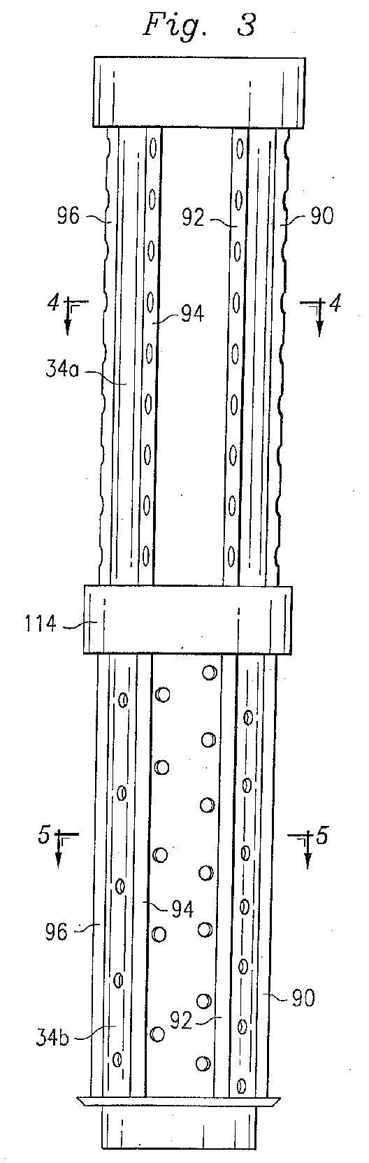
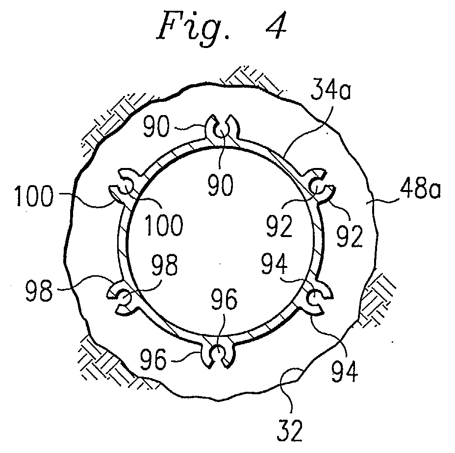
- conduits 90, 92, 94, 96, 98 and 100 are fixed to, and are angularly spaced around, the casing 34 and, as such, are insertable alongside the casing 34 into the wellbore 32.
- the conduits 90, 92, 94, 96, 98 and 100 have diameters substantially less that that of the casing 34, and are fixed to the casing 34 by being either integral with the casing 34 or connected to an outer wall of the casing 34 (e.g. via welding).
- the conduits 90, 92, 94, 96, 98 and 100 span the entire length of the casing sections 34a, 34b, 34c, 34d, 34e, and 34f, and the remaining portions of the conduits extend up the remaining length of the casing 34 and the wellbore 32 to the platform 12.
- a series of axially-spaced perforations extend through the outer arcuate portions of those portions of the conduits 90, 92, 94, 96, 98, and 100 extending adjacent the casing sections 34a, 34c and 34f, while the portions of the conduits extending adjacent the casing sections 34b, 34d, and 34e are not perforated.
- the casing section 34f has a closed lower end, and the lower end portions of the conduits 90, 92, 94, and 96, are bent radially inwardly so as to register with corresponding openings formed through the lower end portion of the casing section 34f, to communicate the casing 34 with the conduits for reasons to be described.
- the conduits 98 and 100 are bent and register with the casing section 34f in the same manner.
- the adjacent casing sections 34a and 34b are connected, at their corresponding ends in a manner depicted in Figs. 7 and 8.
- the casing section 34a includes an internally threaded coupling 108
- the casing section 34b includes an externally threaded coupling 110.
- the coupling 110 is screwed into the coupling 108 to connect the casing sections 34a and 34b.
- a flange 112 of the casing section 34a connects to a shroud 114 (Figs. 7 and 8) of the casing section 34b in any conventional manner.
- the flange 112, the shroud 114, and the corresponding outer surfaces of the couplings 108 and 110 together define a space 118 (Fig. 8).
- the space 118 is positioned between (and fluidly connects) the sections of the conduits 90, 92, 94, 96, 98 and 100 extending adjacent the casing sections 34a and 34b, and thus operates as a mixer for re-mixing a slurry as it flows through the conduits in a manner to be described.
- the casing section 34b is perforated for a great majority of its length, its upper end portion extending adjacent the shroud 114 is not perforated, so that the interior of the casing section 34b is substantially isolated from the space 118.
- a plug 124 is shown in Fig. 9 and comprises a substantially cylindrical body member 124a having a plurality of axially-spaced wipers 124b extending from the body member.
- the plug 124 is conventional, and its function will be described in detail.
- a first material such as a conformance agent or cement slurry
- a first material such as a conformance agent or cement slurry
- the plug 124 is then inserted into the upper end of the casing 34 and is pushed, in a conventional manner, through the casing 34 to force substantially all of the material out the above mentioned openings in the casing section 34f and into the bent end portions of the conduits 90, 92, 94, 96, 98 and 100 for flow upwardly through the conduits.
- the material can be injected directly into the upper end portions of the conduits 90, 92, 94, 96, 98 and 100 directly from the platform 12.
- the material flowing through the conduits 90, 92, 94, 96, 98 and 100 flows out the perforations in those portions of the conduits extending adjacent the non-perforated casing sections 34a, 34c, and 34f to substantially fill the corresponding annuluses 48a, 48c, and 48f, respectively with the material, as shown in Fig. 10.
- the devices 44 and 52 substantially isolate the material in the annulus 48a from the annuluses 48b and 48d, respectively; the devices 46 and 56 substantially isolate the material in the annulus 48c from the annulus 48b and 48e, respectively; and the device 58 substantially isolates the material in the annulus 48f from the annulus 48e.
- the perforations in the casing sections 34b, 34d, and 34e are opened by removing their blockages in the manner discussed above, and a second material, such as a fluid gravel slurry that includes a liquid carrier and a particulate material such as gravel (hereinafter referred to as "slurry"), is injected from the platform 12 into the casing by pumping, or the like.
- a second material such as a fluid gravel slurry that includes a liquid carrier and a particulate material such as gravel (hereinafter referred to as "slurry")
- slurry a fluid gravel slurry that includes a liquid carrier and a particulate material such as gravel
- That portion of the slurry passing into the non-perforated casing sections 34a, 34c and 34f is transferred to their corresponding adjacent perforated sections 34b, 34d, and 34e for discharge in the above manner; while the devices 44, 46, 52, 54, 56 and 58 isolate the adjacent annuluses 48a, 48b, 48c, 48d, 48e and 48f in the manner described above.
- the slurry's particulate material is coated with curable resin (either precoated or coated on-the-fly), so that a hardenable permeable gravel pack mass is formed as a filter in the annuluses 48b, 48d, and 48e.
- curable resin either precoated or coated on-the-fly
- the gravel packs thus formed in the annuluses 48b, 48d, and 48e are highly permeable to the flow of hydrocarbon fluids yet substantially block the flow of particulate material from the hydrocarbon fluids and into the wellhead installation 22 (Fig. 1).
- relatively clean slurry can flow from the annuluses 48b, 48d, and 48e into the different production areas of the productions intervals of the formation 14 and/or return to the platform 12.
- a pre-treating material in the form of a conventional conformance agent, can initially be injected in the casing 34 in the manner discussed above to protect against invasion of water or gas during subsequent production of hydrocarbon materials through the wellbore 32.
- the cement slurry or alternative bonding agent can be introduced, as discussed above.
- the slurry referred to above can include a conventional permeable particulate material, such as gravel, sand, proppant, resin-coated proppant, permeable cement, open cell foam, beads of polymers, metals, ceramics, and similar materials.
- slurry's particulate material in the annuluses 48b, 48d, and 48e.
- a sand control screen can be installed, and the slurry's particulate material can be placed around the screen.
- Expandable screens can also be installed inside the casing and expanded against the perforated casing after the placement of permeable particulate material described above in the annuluses 48b, 48d, and 48e.
- FIG. 1 shows a vertical well and an offshore environment
- the techniques of the illustrative embodiments are equally well-suited for application in deviated wells, inclined wells, horizontal wells, and/or onshore environments.
- the shroud 114 rather than being formed integrally with the casing section 34b, can be separately formed and then connected to the casing section 34b.
- the casing sections 34b, 34d and 34e can be inserted into the wellbore 32 in a non-perforated condition and then a conventional perforating gun can be inserted into the casing to fire charges for perforating the casing sections.
- spatial references such as “upper,” “lower,” “outer,” “inner,” “over,” “between,” “radially” and “axially,” are for the purpose of illustration only and do not limit the specific orientation or location of the structure described above.
Landscapes
- Engineering & Computer Science (AREA)
- Mining & Mineral Resources (AREA)
- Geology (AREA)
- Life Sciences & Earth Sciences (AREA)
- Fluid Mechanics (AREA)
- Environmental & Geological Engineering (AREA)
- Physics & Mathematics (AREA)
- General Life Sciences & Earth Sciences (AREA)
- Geochemistry & Mineralogy (AREA)
- Chemical & Material Sciences (AREA)
- Dispersion Chemistry (AREA)
- Mechanical Engineering (AREA)
- Consolidation Of Soil By Introduction Of Solidifying Substances Into Soil (AREA)
- Extraction Or Liquid Replacement (AREA)
Abstract
Description
Claims (24)
- Apparatus for transferring material in a wellbore, comprising: a pipe insertable into the wellbore; and a conduit fixed to the pipe, insertable alongside the pipe into the wellbore, and having a first section with a perforated wall and a second section with an unperforated wall, such that the material is injectable into the conduit and out the perforated wall of the first section of the conduit.
- Apparatus according to claim 1, wherein the material is injectable into the conduit from the pipe.
- Apparatus according to claim 2, wherein the material is injectable into the conduit from the pipe by connecting an end of the conduit to a first end of the pipe, inserting the material into a second end of the pipe, inserting a plug into the second end of the pipe, and pushing the plug through the pipe to force the inserted material out the first end of the pipe into the conduit.
- Apparatus according to claim 2 or 3, wherein the pipe has perforations that are openable after the material is injected into the conduit from the pipe.
- Apparatus according to claim 4, wherein the perforations are openable by inserting a perforating gun into the pipe and firing a charge from the perforating gun, or by removing a removable sealant from the perforations.
- Apparatus according to claim 5, wherein the removable sealant is such that it is removable from the perforations by applying heat to the pipe, or by applying frequency waves to the pipe, or by injecting a dissolving fluid into the pipe.
- Apparatus according to any of claims 1 to 6, wherein the conduit is fixed to the pipe by being integral with the pipe.
- Apparatus according to any of claims 1 to 7, wherein the conduit is fixed to the pipe by being connected to an outer wall of the pipe.
- Apparatus according to any of claims 1 to 8, further comprising: a device insertable into the wellbore between the first and second sections of the conduit, such that the material is injectable into the conduit and out the perforated wall of the first section of the conduit to substantially fill a first region between the wellbore and the first section of the conduit, while the device substantially isolates the material from reaching a second region between the wellbore and the second section of the conduit.
- Apparatus according to claim 9, wherein the device includes a packer, or a centralizer.
- Apparatus according to claim 9 or 10, wherein the first section of the conduit is aligned with a first section of the pipe, and the second section of the conduit is aligned with a second section of the pipe.
- Apparatus according to claim 11, wherein the material is a first material, and the second section of the pipe has perforations, such that a second material is injectable into the pipe and out the perforations to substantially fill the second region, while the device substantially isolates the second material from reaching the first region.
- Apparatus according to claim 11 or 12 wherein: the first section of the pipe is interposed between the second section and a third section of the pipe; and the first section of the conduit is interposed between the second section and a third section of the conduit, the third section of the conduit having an unperforated wall.
- Apparatus according to claim 18 wherein the device is a first device, the material is a first material, and the second and third sections of the pipe have perforations, and comprising: a second device insertable into the wellbore between the first and third sections of the conduit, such that: the first material is injectable into the conduit and out the perforated wall of the first section of the conduit to substantially fill the first region, while the second device substantially isolates the first material from reaching a third region between the wellbore and the third section of the conduit; and a second material is injectable into the pipe and out the perforations to substantially fill the second and third regions, while the first and second devices substantially isolate the second material from reaching the first region.
- Apparatus according to any of claims 9 to 14, wherein the first section of the conduit is aligned with a first section of the pipe, and the second section of the conduit is aligned with a second section of the pipe.
- A method of transferring material in a wellbore, comprising: inserting a pipe into the wellbore; inserting a conduit alongside the pipe into the wellbore, the conduit being fixed to the pipe and having a first section with a perforated wall and a second section with an unperforated wall; and injecting the material into the conduit and out the perforated wall of the first section of the conduit.
- A method according to claim 16, wherein there is used an apparatus as claimed in any of claims 1 to 15.
- A method of transferring material into an annulus defined between a wellbore and a casing in a ground formation, the method comprising a first flowable material into the casing, directing the first material from the casing into a conduit, directing the first material from the conduit into a first area of the annulus, and directing a second material from the casing directly into a second area of the annulus.
- A method according to claim 18, wherein first area of the annulus is located adjacent a non-production interval of the formation, and wherein the second area of the annulus is located adjacent a production interval of the formation.
- A method according to claim 18 or 19, wherein the first material is a cement and wherein the second material is a granular packing material.
- Apparatus for transferring material in a wellbore comprising at least one casing section disposed in the wellbore to define an annulus between the wellbore and the casing section, the casing section having a blocked opening formed therethrough, at least one conduit disposed adjacent the casing section and in flow communication with the casing section, means for introducing a first flowable material into the casing section with the opening blocked to direct the material to the conduit, and means for introducing a second flowable material into the casing section with the opening unblocked to direct the material directly into the annulus.
- Apparatus according to claim 21, wherein the conduit directs the first material into the annulus.
- Apparatus according to claim 21 or 22, wherein at least one perforation is formed through the conduit to direct the first material into the annulus.
- Apparatus according to claim 23, wherein the openings in the casing section and the perforations in the conduit are at different locations in the wellbore.
Applications Claiming Priority (2)
| Application Number | Priority Date | Filing Date | Title |
|---|---|---|---|
| US205093 | 1994-03-02 | ||
| US10/205,093 US6793017B2 (en) | 2002-07-24 | 2002-07-24 | Method and apparatus for transferring material in a wellbore |
Publications (2)
| Publication Number | Publication Date |
|---|---|
| EP1384851A2 true EP1384851A2 (en) | 2004-01-28 |
| EP1384851A3 EP1384851A3 (en) | 2005-04-06 |
Family
ID=27804769
Family Applications (1)
| Application Number | Title | Priority Date | Filing Date |
|---|---|---|---|
| EP03254470A Withdrawn EP1384851A3 (en) | 2002-07-24 | 2003-07-17 | Method and apparatus for installing casing in a well |
Country Status (6)
| Country | Link |
|---|---|
| US (1) | US6793017B2 (en) |
| EP (1) | EP1384851A3 (en) |
| BR (1) | BR0302409A (en) |
| CA (1) | CA2435451A1 (en) |
| MX (1) | MXPA03006591A (en) |
| NO (1) | NO20033256D0 (en) |
Cited By (2)
| Publication number | Priority date | Publication date | Assignee | Title |
|---|---|---|---|---|
| WO2009063165A1 (en) * | 2007-11-14 | 2009-05-22 | Halliburton Energy Services, Inc. | Methods for controlling migration of particulates in a subterranean formation |
| CN111058796A (en) * | 2019-11-25 | 2020-04-24 | 西南石油大学 | Method for improving shale gas well oil layer casing well cementation quality |
Families Citing this family (15)
| Publication number | Priority date | Publication date | Assignee | Title |
|---|---|---|---|---|
| US7032665B1 (en) * | 2001-11-21 | 2006-04-25 | Berrier Mark L | System and method for gravel packaging a well |
| US7207383B2 (en) * | 2002-02-25 | 2007-04-24 | Schlumberger Technology Corporation | Multiple entrance shunt |
| US6796377B2 (en) * | 2002-07-23 | 2004-09-28 | Halliburton Energy Services, Inc. | Anti-rotation apparatus for limiting rotation of cementing plugs |
| US20040112605A1 (en) * | 2002-12-17 | 2004-06-17 | Nguyen Philip D. | Downhole systems and methods for removing particulate matter from produced fluids |
| US7540325B2 (en) * | 2005-03-14 | 2009-06-02 | Presssol Ltd. | Well cementing apparatus and method |
| CA2539511A1 (en) * | 2005-03-14 | 2006-09-14 | James I. Livingstone | Method and apparatus for cementing a well using concentric tubing or drill pipe |
| US8783351B2 (en) * | 2011-06-21 | 2014-07-22 | Fike Corporation | Method and apparatus for cementing a wellbore |
| US8950487B2 (en) * | 2011-12-06 | 2015-02-10 | Schlumberger Technology Corporation | Assemblies and methods for minimizing pressure-wave damage |
| CN108331562A (en) * | 2018-02-05 | 2018-07-27 | 中国石油大学(北京) | A kind of anti-stifled sand control screen of flexibility wide spectrum |
| US10689955B1 (en) | 2019-03-05 | 2020-06-23 | SWM International Inc. | Intelligent downhole perforating gun tube and components |
| US11078762B2 (en) | 2019-03-05 | 2021-08-03 | Swm International, Llc | Downhole perforating gun tube and components |
| US12291945B1 (en) | 2019-03-05 | 2025-05-06 | Swm International, Llc | Downhole perforating gun system |
| US11268376B1 (en) | 2019-03-27 | 2022-03-08 | Acuity Technical Designs, LLC | Downhole safety switch and communication protocol |
| US11619119B1 (en) | 2020-04-10 | 2023-04-04 | Integrated Solutions, Inc. | Downhole gun tube extension |
| CN115387816B (en) * | 2022-08-23 | 2025-08-26 | 中国路桥工程有限责任公司 | A new method for determining the support and excavation methods of highway tunnels |
Family Cites Families (87)
| Publication number | Priority date | Publication date | Assignee | Title |
|---|---|---|---|---|
| US2135909A (en) | 1936-08-21 | 1938-11-08 | Tretolite Co | Process for removing mud sheaths from geological formations |
| US2190989A (en) | 1937-12-13 | 1940-02-20 | Mordica O Johnston | Method of preparing an oil well for production |
| US2187895A (en) | 1938-03-28 | 1940-01-23 | Stanolind Oil & Gas Co | Method of forming a porous concrete well strainer |
| US2193808A (en) | 1938-07-27 | 1940-03-19 | Dow Chemical Co | Cementing practice for earth wells |
| US2344909A (en) | 1940-04-15 | 1944-03-21 | Edward E Johnson Inc | Deep well screen |
| US2342913A (en) | 1940-04-15 | 1944-02-29 | Edward E Johnson Inc | Deep well screen |
| US2288557A (en) | 1940-06-20 | 1942-06-30 | Gulf Research Development Co | Method of and composition for providing permeable cement packs in wells |
| US3044547A (en) | 1958-10-23 | 1962-07-17 | Cities Service Res & Dev Co | Permeable well cement and method of providing permeable cement filters in wells |
| US3119448A (en) | 1962-10-05 | 1964-01-28 | Cities Service Res & Dev Co | Permeable well cement |
| US3216497A (en) * | 1962-12-20 | 1965-11-09 | Pan American Petroleum Corp | Gravel-packing method |
| US3368623A (en) | 1965-05-03 | 1968-02-13 | Halliburton Co | Permeable cement for wells |
| US3605899A (en) | 1969-11-28 | 1971-09-20 | Texaco Inc | Method of increasing permeability of cement packs |
| US3816151A (en) | 1972-08-03 | 1974-06-11 | Hercules Inc | Self-destructing gels |
| US4042032A (en) | 1973-06-07 | 1977-08-16 | Halliburton Company | Methods of consolidating incompetent subterranean formations using aqueous treating solutions |
| US3862663A (en) | 1973-12-28 | 1975-01-28 | Texaco Inc | Method for stabilizing incompetent oil-containing formations |
| US4070865A (en) | 1976-03-10 | 1978-01-31 | Halliburton Company | Method of consolidating porous formations using vinyl polymer sealer with divinylbenzene crosslinker |
| US4018283A (en) * | 1976-03-25 | 1977-04-19 | Exxon Production Research Company | Method and apparatus for gravel packing wells |
| US4074760A (en) | 1976-11-01 | 1978-02-21 | The Dow Chemical Company | Method for forming a consolidated gravel pack |
| US4336842A (en) | 1981-01-05 | 1982-06-29 | Graham John W | Method of treating wells using resin-coated particles |
| US4829100A (en) | 1987-10-23 | 1989-05-09 | Halliburton Company | Continuously forming and transporting consolidatable resin coated particulate materials in aqueous gels |
| US4945991A (en) | 1989-08-23 | 1990-08-07 | Mobile Oil Corporation | Method for gravel packing wells |
| US5062484A (en) | 1990-08-24 | 1991-11-05 | Marathon Oil Company | Method of gravel packing a subterranean well |
| US5128390A (en) | 1991-01-22 | 1992-07-07 | Halliburton Company | Methods of forming consolidatable resin coated particulate materials in aqueous gels |
| US5082052A (en) | 1991-01-31 | 1992-01-21 | Mobil Oil Corporation | Apparatus for gravel packing wells |
| US5113935A (en) | 1991-05-01 | 1992-05-19 | Mobil Oil Corporation | Gravel packing of wells |
| US5161613A (en) | 1991-08-16 | 1992-11-10 | Mobil Oil Corporation | Apparatus for treating formations using alternate flowpaths |
| US5161618A (en) | 1991-08-16 | 1992-11-10 | Mobil Oil Corporation | Multiple fractures from a single workstring |
| US5355956A (en) | 1992-09-28 | 1994-10-18 | Halliburton Company | Plugged base pipe for sand control |
| US5363916A (en) | 1992-12-21 | 1994-11-15 | Halliburton Company | Method of gravel packing a well |
| US5333688A (en) | 1993-01-07 | 1994-08-02 | Mobil Oil Corporation | Method and apparatus for gravel packing of wells |
| US5339902A (en) | 1993-04-02 | 1994-08-23 | Halliburton Company | Well cementing using permeable cement |
| GB9313081D0 (en) | 1993-06-25 | 1993-08-11 | Pumptech Nv | Selective zonal isolation of oil wells |
| US5390966A (en) | 1993-10-22 | 1995-02-21 | Mobil Oil Corporation | Single connector for shunt conduits on well tool |
| US5381864A (en) | 1993-11-12 | 1995-01-17 | Halliburton Company | Well treating methods using particulate blends |
| US5419394A (en) | 1993-11-22 | 1995-05-30 | Mobil Oil Corporation | Tools for delivering fluid to spaced levels in a wellbore |
| US5559086A (en) | 1993-12-13 | 1996-09-24 | Halliburton Company | Epoxy resin composition and well treatment method |
| US5393810A (en) | 1993-12-30 | 1995-02-28 | Halliburton Company | Method and composition for breaking crosslinked gels |
| US5443117A (en) | 1994-02-07 | 1995-08-22 | Halliburton Company | Frac pack flow sub |
| US5435391A (en) * | 1994-08-05 | 1995-07-25 | Mobil Oil Corporation | Method for fracturing and propping a formation |
| US5595246A (en) * | 1995-02-14 | 1997-01-21 | Baker Hughes Incorporated | One trip cement and gravel pack system |
| US5839510A (en) | 1995-03-29 | 1998-11-24 | Halliburton Energy Services, Inc. | Control of particulate flowback in subterranean wells |
| US5529123A (en) | 1995-04-10 | 1996-06-25 | Atlantic Richfield Company | Method for controlling fluid loss from wells into high conductivity earth formations |
| US5515915A (en) | 1995-04-10 | 1996-05-14 | Mobil Oil Corporation | Well screen having internal shunt tubes |
| US5588487A (en) | 1995-09-12 | 1996-12-31 | Mobil Oil Corporation | Tool for blocking axial flow in gravel-packed well annulus |
| US5636691A (en) | 1995-09-18 | 1997-06-10 | Halliburton Energy Services, Inc. | Abrasive slurry delivery apparatus and methods of using same |
| US5722490A (en) | 1995-12-20 | 1998-03-03 | Ely And Associates, Inc. | Method of completing and hydraulic fracturing of a well |
| US6047773A (en) | 1996-08-09 | 2000-04-11 | Halliburton Energy Services, Inc. | Apparatus and methods for stimulating a subterranean well |
| US5960880A (en) | 1996-08-27 | 1999-10-05 | Halliburton Energy Services, Inc. | Unconsolidated formation stimulation with sand filtration |
| US5848645A (en) | 1996-09-05 | 1998-12-15 | Mobil Oil Corporation | Method for fracturing and gravel-packing a well |
| WO1998019042A2 (en) | 1996-10-25 | 1998-05-07 | Baker Hughes Incorporated | Method and apparatus to isolate a formation zone |
| US6116343A (en) | 1997-02-03 | 2000-09-12 | Halliburton Energy Services, Inc. | One-trip well perforation/proppant fracturing apparatus and methods |
| US5842516A (en) | 1997-04-04 | 1998-12-01 | Mobil Oil Corporation | Erosion-resistant inserts for fluid outlets in a well tool and method for installing same |
| US5868200A (en) | 1997-04-17 | 1999-02-09 | Mobil Oil Corporation | Alternate-path well screen having protected shunt connection |
| US5921318A (en) | 1997-04-21 | 1999-07-13 | Halliburton Energy Services, Inc. | Method and apparatus for treating multiple production zones |
| US5924488A (en) | 1997-06-11 | 1999-07-20 | Halliburton Energy Services, Inc. | Methods of preventing well fracture proppant flow-back |
| US6070663A (en) | 1997-06-16 | 2000-06-06 | Shell Oil Company | Multi-zone profile control |
| US5890533A (en) | 1997-07-29 | 1999-04-06 | Mobil Oil Corporation | Alternate path well tool having an internal shunt tube |
| US5921317A (en) | 1997-08-14 | 1999-07-13 | Halliburton Energy Services, Inc. | Coating well proppant with hardenable resin-fiber composites |
| US5964296A (en) | 1997-09-18 | 1999-10-12 | Halliburton Energy Services, Inc. | Formation fracturing and gravel packing tool |
| US6003600A (en) | 1997-10-16 | 1999-12-21 | Halliburton Energy Services, Inc. | Methods of completing wells in unconsolidated subterranean zones |
| US6059032A (en) | 1997-12-10 | 2000-05-09 | Mobil Oil Corporation | Method and apparatus for treating long formation intervals |
| US6286600B1 (en) | 1998-01-13 | 2001-09-11 | Texaco Inc. | Ported sub treatment system |
| US6016870A (en) | 1998-06-11 | 2000-01-25 | Halliburton Energy Services, Inc. | Compositions and methods for consolidating unconsolidated subterranean zones |
| US6354378B1 (en) | 1998-11-18 | 2002-03-12 | Schlumberger Technology Corporation | Method and apparatus for formation isolation in a well |
| US6302216B1 (en) | 1998-11-18 | 2001-10-16 | Schlumberger Technology Corp. | Flow control and isolation in a wellbore |
| US6230803B1 (en) | 1998-12-03 | 2001-05-15 | Baker Hughes Incorporated | Apparatus and method for treating and gravel-packing closely spaced zones |
| US6318469B1 (en) | 1999-02-09 | 2001-11-20 | Schlumberger Technology Corp. | Completion equipment having a plurality of fluid paths for use in a well |
| US6227303B1 (en) | 1999-04-13 | 2001-05-08 | Mobil Oil Corporation | Well screen having an internal alternate flowpath |
| US6063738A (en) | 1999-04-19 | 2000-05-16 | Halliburton Energy Services, Inc. | Foamed well cement slurries, additives and methods |
| US6220345B1 (en) | 1999-08-19 | 2001-04-24 | Mobil Oil Corporation | Well screen having an internal alternate flowpath |
| US6298916B1 (en) * | 1999-12-17 | 2001-10-09 | Schlumberger Technology Corporation | Method and apparatus for controlling fluid flow in conduits |
| US6311773B1 (en) | 2000-01-28 | 2001-11-06 | Halliburton Energy Services, Inc. | Resin composition and methods of consolidating particulate solids in wells with or without closure pressure |
| US6202751B1 (en) | 2000-07-28 | 2001-03-20 | Halliburton Energy Sevices, Inc. | Methods and compositions for forming permeable cement sand screens in well bores |
| US6644406B1 (en) * | 2000-07-31 | 2003-11-11 | Mobil Oil Corporation | Fracturing different levels within a completion interval of a well |
| US7222676B2 (en) * | 2000-12-07 | 2007-05-29 | Schlumberger Technology Corporation | Well communication system |
| US6557634B2 (en) * | 2001-03-06 | 2003-05-06 | Halliburton Energy Services, Inc. | Apparatus and method for gravel packing an interval of a wellbore |
| US6588506B2 (en) * | 2001-05-25 | 2003-07-08 | Exxonmobil Corporation | Method and apparatus for gravel packing a well |
| US6749023B2 (en) * | 2001-06-13 | 2004-06-15 | Halliburton Energy Services, Inc. | Methods and apparatus for gravel packing, fracturing or frac packing wells |
| US20020189808A1 (en) * | 2001-06-13 | 2002-12-19 | Nguyen Philip D. | Methods and apparatus for gravel packing or frac packing wells |
| US6516881B2 (en) * | 2001-06-27 | 2003-02-11 | Halliburton Energy Services, Inc. | Apparatus and method for gravel packing an interval of a wellbore |
| US6581689B2 (en) * | 2001-06-28 | 2003-06-24 | Halliburton Energy Services, Inc. | Screen assembly and method for gravel packing an interval of a wellbore |
| US6588507B2 (en) * | 2001-06-28 | 2003-07-08 | Halliburton Energy Services, Inc. | Apparatus and method for progressively gravel packing an interval of a wellbore |
| US6601646B2 (en) * | 2001-06-28 | 2003-08-05 | Halliburton Energy Services, Inc. | Apparatus and method for sequentially packing an interval of a wellbore |
| US6719051B2 (en) * | 2002-01-25 | 2004-04-13 | Halliburton Energy Services, Inc. | Sand control screen assembly and treatment method using the same |
| US6899176B2 (en) * | 2002-01-25 | 2005-05-31 | Halliburton Energy Services, Inc. | Sand control screen assembly and treatment method using the same |
| US6715545B2 (en) * | 2002-03-27 | 2004-04-06 | Halliburton Energy Services, Inc. | Transition member for maintaining for fluid slurry velocity therethrough and method for use of same |
| US6776238B2 (en) * | 2002-04-09 | 2004-08-17 | Halliburton Energy Services, Inc. | Single trip method for selectively fracture packing multiple formations traversed by a wellbore |
-
2002
- 2002-07-24 US US10/205,093 patent/US6793017B2/en not_active Expired - Fee Related
-
2003
- 2003-07-16 CA CA002435451A patent/CA2435451A1/en not_active Abandoned
- 2003-07-17 EP EP03254470A patent/EP1384851A3/en not_active Withdrawn
- 2003-07-18 NO NO20033256A patent/NO20033256D0/en unknown
- 2003-07-21 BR BR0302409-1A patent/BR0302409A/en not_active IP Right Cessation
- 2003-07-23 MX MXPA03006591A patent/MXPA03006591A/en unknown
Cited By (3)
| Publication number | Priority date | Publication date | Assignee | Title |
|---|---|---|---|---|
| WO2009063165A1 (en) * | 2007-11-14 | 2009-05-22 | Halliburton Energy Services, Inc. | Methods for controlling migration of particulates in a subterranean formation |
| US7690431B2 (en) | 2007-11-14 | 2010-04-06 | Halliburton Energy Services, Inc. | Methods for controlling migration of particulates in a subterranean formation |
| CN111058796A (en) * | 2019-11-25 | 2020-04-24 | 西南石油大学 | Method for improving shale gas well oil layer casing well cementation quality |
Also Published As
| Publication number | Publication date |
|---|---|
| NO20033256D0 (en) | 2003-07-18 |
| MXPA03006591A (en) | 2004-02-12 |
| CA2435451A1 (en) | 2004-01-24 |
| US20040016546A1 (en) | 2004-01-29 |
| BR0302409A (en) | 2004-09-08 |
| US6793017B2 (en) | 2004-09-21 |
| EP1384851A3 (en) | 2005-04-06 |
Similar Documents
| Publication | Publication Date | Title |
|---|---|---|
| US8403062B2 (en) | Wellbore method and apparatus for completion, production and injection | |
| US6793017B2 (en) | Method and apparatus for transferring material in a wellbore | |
| US6601646B2 (en) | Apparatus and method for sequentially packing an interval of a wellbore | |
| AU2007243920B2 (en) | Wellbore method and apparatus for sand and inflow control during well operations | |
| US6766862B2 (en) | Expandable sand control device and specialized completion system and method | |
| US6886634B2 (en) | Sand control screen assembly having an internal isolation member and treatment method using the same | |
| US6601648B2 (en) | Well completion method | |
| EP3036395B1 (en) | One trip perforating and washing tool for plugging and abandoning wells | |
| US20040134656A1 (en) | Sand control screen assembly having an internal seal element and treatment method using the same | |
| US6715543B1 (en) | Particulate matter plug for plugging a well | |
| WO2001027436A1 (en) | Well-perforating and/or packing apparatus and method | |
| EP0982469A2 (en) | Wellbore apparatus | |
| CN101375015B (en) | Wellbore operation method | |
| US20060037752A1 (en) | Rat hole bypass for gravel packing assembly | |
| AU2012216300B2 (en) | Wellbore method and apparatus for sand and inflow control during well operations | |
| BRPI0621246B1 (en) | METHOD FOR OPERATING A WELL |
Legal Events
| Date | Code | Title | Description |
|---|---|---|---|
| PUAI | Public reference made under article 153(3) epc to a published international application that has entered the european phase |
Free format text: ORIGINAL CODE: 0009012 |
|
| AK | Designated contracting states |
Kind code of ref document: A2 Designated state(s): AT BE BG CH CY CZ DE DK EE ES FI FR GB GR HU IE IT LI LU MC NL PT RO SE SI SK TR |
|
| AX | Request for extension of the european patent |
Extension state: AL LT LV MK |
|
| PUAL | Search report despatched |
Free format text: ORIGINAL CODE: 0009013 |
|
| AK | Designated contracting states |
Kind code of ref document: A3 Designated state(s): AT BE BG CH CY CZ DE DK EE ES FI FR GB GR HU IE IT LI LU MC NL PT RO SE SI SK TR |
|
| AX | Request for extension of the european patent |
Extension state: AL LT LV MK |
|
| 17P | Request for examination filed |
Effective date: 20050906 |
|
| AKX | Designation fees paid |
Designated state(s): DE FR GB IT NL |
|
| STAA | Information on the status of an ep patent application or granted ep patent |
Free format text: STATUS: THE APPLICATION IS DEEMED TO BE WITHDRAWN |
|
| 18D | Application deemed to be withdrawn |
Effective date: 20070201 |