EP1384850A2 - Downhole packer with anti rotating device - Google Patents
Downhole packer with anti rotating device Download PDFInfo
- Publication number
- EP1384850A2 EP1384850A2 EP03078179A EP03078179A EP1384850A2 EP 1384850 A2 EP1384850 A2 EP 1384850A2 EP 03078179 A EP03078179 A EP 03078179A EP 03078179 A EP03078179 A EP 03078179A EP 1384850 A2 EP1384850 A2 EP 1384850A2
- Authority
- EP
- European Patent Office
- Prior art keywords
- downhole
- well
- downhole tool
- tool
- drill
- Prior art date
- Legal status (The legal status is an assumption and is not a legal conclusion. Google has not performed a legal analysis and makes no representation as to the accuracy of the status listed.)
- Withdrawn
Links
- 238000007789 sealing Methods 0.000 claims abstract description 35
- 238000009987 spinning Methods 0.000 claims abstract description 12
- 239000000463 material Substances 0.000 claims abstract description 4
- 239000000919 ceramic Substances 0.000 claims description 11
- 238000005553 drilling Methods 0.000 claims description 10
- 238000000034 method Methods 0.000 claims description 9
- 239000012530 fluid Substances 0.000 description 19
- 239000002002 slurry Substances 0.000 description 6
- 241001331845 Equus asinus x caballus Species 0.000 description 4
- 230000015572 biosynthetic process Effects 0.000 description 4
- 229910001018 Cast iron Inorganic materials 0.000 description 3
- 230000035515 penetration Effects 0.000 description 3
- XEEYBQQBJWHFJM-UHFFFAOYSA-N Iron Chemical compound [Fe] XEEYBQQBJWHFJM-UHFFFAOYSA-N 0.000 description 2
- 229920003023 plastic Polymers 0.000 description 2
- 239000004033 plastic Substances 0.000 description 2
- 125000006850 spacer group Chemical group 0.000 description 2
- 229910000831 Steel Inorganic materials 0.000 description 1
- 239000004568 cement Substances 0.000 description 1
- 238000004891 communication Methods 0.000 description 1
- 239000002131 composite material Substances 0.000 description 1
- 238000005520 cutting process Methods 0.000 description 1
- 229910052742 iron Inorganic materials 0.000 description 1
- 238000004519 manufacturing process Methods 0.000 description 1
- 239000002184 metal Substances 0.000 description 1
- 229910052751 metal Inorganic materials 0.000 description 1
- 238000012986 modification Methods 0.000 description 1
- 230000004048 modification Effects 0.000 description 1
- 239000003129 oil well Substances 0.000 description 1
- 238000012856 packing Methods 0.000 description 1
- 230000000717 retained effect Effects 0.000 description 1
- 230000006641 stabilisation Effects 0.000 description 1
- 238000011105 stabilization Methods 0.000 description 1
- 239000010959 steel Substances 0.000 description 1
- 238000012360 testing method Methods 0.000 description 1
Images


Classifications
-
- E—FIXED CONSTRUCTIONS
- E21—EARTH OR ROCK DRILLING; MINING
- E21B—EARTH OR ROCK DRILLING; OBTAINING OIL, GAS, WATER, SOLUBLE OR MELTABLE MATERIALS OR A SLURRY OF MINERALS FROM WELLS
- E21B33/00—Sealing or packing boreholes or wells
- E21B33/10—Sealing or packing boreholes or wells in the borehole
- E21B33/12—Packers; Plugs
- E21B33/128—Packers; Plugs with a member expanded radially by axial pressure
-
- E—FIXED CONSTRUCTIONS
- E21—EARTH OR ROCK DRILLING; MINING
- E21B—EARTH OR ROCK DRILLING; OBTAINING OIL, GAS, WATER, SOLUBLE OR MELTABLE MATERIALS OR A SLURRY OF MINERALS FROM WELLS
- E21B33/00—Sealing or packing boreholes or wells
- E21B33/10—Sealing or packing boreholes or wells in the borehole
- E21B33/12—Packers; Plugs
- E21B33/129—Packers; Plugs with mechanical slips for hooking into the casing
- E21B33/1294—Packers; Plugs with mechanical slips for hooking into the casing characterised by a valve, e.g. a by-pass valve
Definitions
- This invention relates generally to downhole apparatus for use in oil and gas wellbores and, more particularly, to a downhole valved packer or frac plug.
- downhole tools In the drilling or reworking of oil wells, a great variety of downhole tools are used. For example, but not by way of limitation, it is often desirable to seal tubing or other pipe in the casing of the well, such as when it is desired to pump cement or other slurry down the tubing and force the slurry out into a formation. It thus becomes necessary to seal the tubing with respect to the well casing and to prevent the fluid pressure of the slurry from lifting the tubing out of the well. Downhole tools referred to as packers and bridge plugs are designed for these general purposes and are well known in the art of producing oil and gas.
- the EZ Drill SV® squeeze packer for example includes a set ring housing, upper slip wedge, lower slip wedge, and lower slip support made of soft cast iron. These components are mounted on a mandrel made of medium hardness cast iron.
- the EZ Drill® squeeze packer is similarly constructed.
- the Halliburton EZ Drill® bridge plug is also similar, except that it does not provide for fluid flow therethrough.
- the EZ Drill® packer and bridge plug and the EZ Drill SV® packer are designed for fast removal from the well bore by either rotary or cable tool drilling methods. Many of the components in these drillable packing devices are locked together to prevent their spinning while being drilled, and the harder slips are grooved so that they will be broken up in small pieces.
- standard "tri-cone" rotary drill bits are used which are rotated at speeds of about 75 to about 120 rpm. A load of about 5,000 to about 7,000 pounds of weight is applied to the bit for initial drilling and increased as necessary to drill out the remainder of the packer or bridge plug, depending upon its size. Drill collars may be used as required for weight and bit stabilization.
- Such drillable devices have worked well and provide improved operating performance at relatively high temperatures and pressures.
- the packers and bridge plugs mentioned above are designed to withstand pressures of about 10,000 psi (700 Kg/cm 2 ) and temperatures of about 425°F. (220°C.) after being set in the well bore. Such pressures and temperatures require using the cast iron components previously discussed.
- bit tracking can occur, wherein the drill bit stays on one path and no longer cuts into the downhole tool. When this happens, it is necessary to pick up the bit above the drilling surface and rapidly recontact the bit with the packer or plug and apply weight while continuing rotation. This aids in breaking up the established bit pattern and helps to reestablish bit penetration. If this procedure is used, there are rarely problems. However, operators may not apply these techniques or even recognize when bit tracking has occurred. The result is that drilling times are greatly increased because the bit merely wears against the surface of the downhole tool rather than cutting into it to break it up.
- the FAS DRILL® line of tools consists of a majority of the components being made of non-metallic engineering grade plastics to greatly improve the drillability of such downhole tools.
- slips metallic or non-metallic slip-elements, or slips, that are initially retained in close proximity to the mandrel but are forced outwardly away from the mandrel of the tool to engage a casing previously installed within the wellbore in which operations are to be conducted upon the tool being set.
- slips upon the tool being positioned at the desired depth, the slips are forced outwardly against the wellbore to secure the packer, or bridge plug as the case may be, so that the tool will not move relative to the casing when for example operations are being conducted for tests, to stimulate production of the well, or to plug all or a portion of the well.
- the FAS DRILL® line of tools includes a frac plug which is well known in the industry.
- a frac plug is essentially a downhole packer with a ball seat for receiving a sealing ball. When the packer is set and the sealing ball engages the ball seat, the casing or other pipe in which the frac plug is set is sealed. Fluid, such as a slurry, can be pumped into the well after the sealing ball engages the seat and forced into a formation above the frac plug. Prior to the seating of the ball, however, flow through the frac plug is allowed.
- One way to seal the frac plug is to drop the sealing ball from the surface after the packer is set. Although ultimately the ball will reach the ball seat and the frac plug will perform its desired function, it takes time for the sealing ball to reach the ball seat, and as the ball is pumped downwardly a substantial amount of fluid can be lost through the frac plug.
- the ball may also be run into the well with the packer. Fluid loss and lost time to get the ball seated can still be a problem, however, especially in deviated wells.
- Some wells are deviated to such an extent that even though the ball is run into the well with the packer, the sealing ball can drift away from the packer as it is lowered into the well through the deviated portions thereof. As is well known, some wells deviate such that they become horizontal or at some portions may even angle slightly upwardly. In those cases, the sealing ball can be separated from the packer a great distance in the well. Thus, a large amount of fluid and time is taken to get the sealing ball moved to the ball seat, so that the frac plug seals the well to prevent flow therethrough.
- Another object of the present invention is to provide a downhole tool that will not spin as it is drilled out.
- the drillable tools described herein When the drillable tools described herein are drilled out, the lower portion of the tool being drilled out will be displaced downwardly in the well once the upper portion of the tool is drilled through. If there is another tool in the well therebelow, the portion of the partially drilled tool will be displaced downwardly in the well and will engage the tool therebelow. As the drill is lowered into the well and engages the portion of the tool that has dropped in the well, that portion of the tool sometimes has a tendency to spin and thus can take longer than is desired to drill out. Thus, there is a need for a downhole tool which will not spin when an undrilled portion of that tool engages another tool in the well as it is being drilled out of the well.
- the present invention provides a downhole apparatus for use in a well, the apparatus comprising: a mandrel having an upper end and a lower end, the mandrel defining a longitudinal central opening for allowing flow therethrough, the mandrel defining a ball seat; a sealing element disposed about said mandrel for sealingly engaging the well; an upper end cap disposed above said ball seat; and a sealing ball trapped between said upper end cap and said ball seat for sealingly engaging said ball seat.
- the invention also provides a downhole apparatus for use in a well, the apparatus comprising: a mandrel having an upper end and a lower end; a slip means disposed on the mandrel for grippingly engaging the well when set into position, said downhole apparatus being an upper downhole apparatus and being comprised of a drillable material wherein at least a portion of said upper downhole apparatus will be displaced downwardly in said well when a drill lowered into said well drills into said downhole apparatus; at least one gripping member disposed in said at least a portion of said upper downhole apparatus for engaging a lower downhole apparatus disposed in said well, wherein said at least one gripping member will engage and grip said lower downhole apparatus to prevent said at least a portion of said upper apparatus from spinning when engaged by a spinning drill bit lowered into said well to drill out said upper downhole apparatus.
- a preferred tool of the invention is in the form of a frac plug which comprises a packer having a ball seat defined therein and a sealing ball for engaging the ball seat.
- the packer has an upper end, a lower end and a longitudinal flow passage therethrough.
- the frac plug of the present invention also has a ball cage disposed at the upper end of the packer.
- the sealing ball is disposed in the ball cage and thus is prevented from moving past a predetermined distance away from the ball seat.
- the packer includes a packer mandrel having an upper and lower end, and has an inner surface that defines the longitudinal flow passage.
- the ball seat is defined by the mandrel, and more particularly by the inner surface thereof.
- a spring may be disposed in the mandrel and has an upper end that engages the sealing ball.
- the spring has a spring force such that it will keep the sealing ball from engaging the ball seat until a predetermined flow in the well is achieved. Once the predetermined flow rate is reached, the sealing ball will compress the spring and will engage the ball seat to close the longitudinal flow passage. Flow downwardly through the longitudinal flow passage is prevented when the sealing ball engages the ball seat.
- the present invention may be used with or without the spring.
- the packer includes slips and a sealing element disposed about the mandrel such that when it is set in the wellbore and when the sealing ball is engaged with the ball seat, no flow past the frac plug is allowed.
- a slurry or other fluid may thus be directed into the formation above the frac plug.
- the ball cage has a plurality of flow ports therein so that fluid may pass therethrough into the longitudinal central opening thus allowing for fluid flow through the frac plug when the packer is set but the sealing ball has not engaged the ball seat. Fluid can flow through the frac plug so long as the flow rate is below the rate which will overcome the spring force and cause the sealing ball to engage the ball seat.
- one object of the present invention is to provide a frac plug which allows for flow therethrough but which alleviates the amount of fluid loss and loss of time normally required for seating a ball on the ball seat of a frac plug. Additional objects and advantages of the invention will become apparent as the following detailed description of a preferred embodiment is read in conjunction with the drawings which illustrate such preferred embodiment:
- Frac plug 10 has an upper end 12 and a lower end 14.
- two frac plugs 10 are shown and may be referred to herein as an upper downhole tool or frac plug 10A and a lower downhole tool or frac plug 10B.
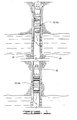
- Frac plugs 10 are schematically shown in FIG. 1 in a set position 15.
- the frac tools shown in FIG. 1 are shown after having been lowered into a well 20 with a setting tool of any type known in the art.
- Well 20 comprises a wellbore 25 having a casing 30 set therein.
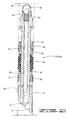
- FIG. 2 a cross-section of the frac plug 10 is shown in an unset position 32.
- the tool shown in FIG. 2 is referred to as a frac plug since it will be utilized to seal the wellbore to prevent flow past the frac plug.
- the frac plug disposed herein may be deployed in wellbores having casings or other such annular structure or geometry in which the tool may be set.
- the overall downhole tool structure is like that typically referred to as a packer, which typically has at least one means for allowing fluid communication through the tool.
- Frac plug 10 thus may be said to comprise a packer 34 having a ball cage or cap 36 extending from the upper end thereof.
- a sealing ball 38 is disposed or housed in ball cage 36.
- Packer 34 comprises a mandrel 40 having an upper end 42, a lower end 44, and an inner surface 46 defining a longitudinal central flow passage 48.
- Mandrel 48 defines a ball seat 50.
- Ball seat 50 is preferably defined at the upper end of mandrel 40.
- Packer 34 includes spacer rings 52 secured to mandrel 40 with pins 54.
- Spacer ring 52 provides an abutment which serves to axially retain slip segments 56 which are positioned circumferentially about mandrel 40.
- Slip segments 56 may utilize ceramic buttons 57 as described in detail in U.S. Pat. No. 5,984,007 the details of which are incorporated herein by reference.
- Slip retaining bands 58 serve to radially retain slips 56 in an initial circumferential position about mandrel 40 as well as slip wedge 60.
- Bands 58 are made of a steel wire, a plastic material, or a composite material having the requisite characteristics of having sufficient strength to hold the slips in place prior to actually setting the tool and to be easily drillable when the tool is to be removed from the wellbore.
- bands 58 are an inexpensive and easily installed about slip segments 56.
- Slip wedge 60 is initially positioned in a slidable relationship to, and partially underneath slip segment 56.
- Slip wedge 60 is shown pinned into place by pins 62.
- Located below slip wedge 60 is at least one packer element, and as shown in FIG. 2, a packer element assembly 64 consisting of three expandable packer elements 66 disposed about packer mandrel 40.
- Packer shoes 68 are disposed at the upper and lower ends of seal assembly 64 and provide axial support thereto.
- the particular packer seal or element arrangement shown in FIG. 2 is merely representative as there are several packer element arrangements known and used within the art.
- a mule shoe 70 is secured to mandrel 40 by radially oriented pins 72.
- Mule shoe 70 extends below the lower end 44 of packer 40 and has a lower end 74, which comprises lower end 14 of tool 10.
- the lower most portion of the tool need not be a mule shoe but could be any type of section which serves to terminate the structure of the tool or serves to be a connector for connecting the tool with other tools, a valve, tubing or other downhole equipment.
- inner surface 46 defines a first diameter 76, a second diameter 78 displaced radially inwardly therefrom, and a shoulder 80 which is defined by and extends between first and second diameters 76 and 78.
- a spring 82 is disposed in mandrel 40. Spring 82 has a lower end 84 and an upper end 86. Lower end 84 engages shoulder 80. Sealing ball 38 rests on the upper end 86 of spring 80.
- Ball cage or ball cap 36 comprises a body portion 88 having an upper end cap 90 connected thereto, and has a plurality of ports 92 therethrough.
- a plurality of ceramic buttons 93 are disposed at or near the lower end 74 of tool 10 and at the lower end 44 of mandrel 40. As will be described in more detail hereinbelow, the ceramic buttons are designed to engage and grip tools positioned in the well therebelow to prevent spinning when the tools are being drilled out.
- Frac plug 10 may be lowered into the wellbore utilizing a setting tool of a type known in the art. As is depicted schematically in FIG. 1, one, two or several frac plugs or tools may be set in the hole. As the frac plug is lowered into the hole, flow therethrough will be allowed since the spring 80 will prevent sealing ball 38 from engaging ball seat 50, while cage 36 prevents ball 80 from moving away from ball seat 50 any further than upper cap 90 will allow.
- a setting tool of a type known in the art can be utilized to move the frac plug from its unset position 32 to the set position 15 as depicted in FIGS. 1 and 3.
- slip segments 56 and sealing element 66 engage casing 30. Fluid may be displaced downward through openings 92 in ball cage 36 and thus into and through longitudinal central flow passage, or opening 48. It may be desirable or necessary in certain circumstances to displace fluid through openings 92 and through frac plug 10. For example, once frac plug 10 has been set it may be desirable to lower a tool into the well, such as a perforating tool, on a wire line. In deviated wells it may be necessary to move the perforating tool to the desired location with fluid flow into the well. If a sealing ball has already seated and could not be removed therefrom, or if a bridge plug was utilized, such fluid flow would not be possible and the perforating or other tool would have to be lowered by other means.
- a tool such as a perforating tool
- Cage 36 thus comprises a retaining means for sealing ball 38, and carries sealing ball 38 with and as part of frac plug 10, and also comprises a means for preventing ball 38 from moving upwardly past a predetermined distance away from ball seat 50.
- any means known in the art may be used to do so.
- the drill has gone through a portion of the frac plug, namely the slips and the sealing element, at least a portion of the frac plug 10, namely the lower end portion which in the embodiment shown will include the mule shoe 70, will fall into or will be pushed into the well by the drill bit. Assuming there are no other tools therebelow, that portion of the frac plug may be left in the hole. However, as shown in FIG. 1, there may be one or more tools below the frac plug.
- ceramic buttons 93 in the upper frac plug 10A will engage the upper end of lower frac plug 10B such that the portion of tool 10A will not spin as it is drilled from the well.
- the ceramic buttons may be utilized with any downhole tool such that spinning relative to the tool therebelow is prevented.
Landscapes
- Geology (AREA)
- Life Sciences & Earth Sciences (AREA)
- Engineering & Computer Science (AREA)
- Mining & Mineral Resources (AREA)
- Environmental & Geological Engineering (AREA)
- Fluid Mechanics (AREA)
- Physics & Mathematics (AREA)
- General Life Sciences & Earth Sciences (AREA)
- Geochemistry & Mineralogy (AREA)
- Consolidation Of Soil By Introduction Of Solidifying Substances Into Soil (AREA)
- Spinning Or Twisting Of Yarns (AREA)
- Taps Or Cocks (AREA)
- Earth Drilling (AREA)
Abstract
Description
- This invention relates generally to downhole apparatus for use in oil and gas wellbores and, more particularly, to a downhole valved packer or frac plug.
- In the drilling or reworking of oil wells, a great variety of downhole tools are used. For example, but not by way of limitation, it is often desirable to seal tubing or other pipe in the casing of the well, such as when it is desired to pump cement or other slurry down the tubing and force the slurry out into a formation. It thus becomes necessary to seal the tubing with respect to the well casing and to prevent the fluid pressure of the slurry from lifting the tubing out of the well. Downhole tools referred to as packers and bridge plugs are designed for these general purposes and are well known in the art of producing oil and gas.
- The EZ Drill SV® squeeze packer, for example includes a set ring housing, upper slip wedge, lower slip wedge, and lower slip support made of soft cast iron. These components are mounted on a mandrel made of medium hardness cast iron. The EZ Drill® squeeze packer is similarly constructed. The Halliburton EZ Drill® bridge plug is also similar, except that it does not provide for fluid flow therethrough.
- All of the above-mentioned packers are disclosed in Halliburton Services-Sales and Service Catalog No 43, pages 2561-2562, and the bridge plug is disclosed in the same catalog on pages 2556-2557.
- The EZ Drill® packer and bridge plug and the EZ Drill SV® packer are designed for fast removal from the well bore by either rotary or cable tool drilling methods. Many of the components in these drillable packing devices are locked together to prevent their spinning while being drilled, and the harder slips are grooved so that they will be broken up in small pieces. Typically, standard "tri-cone" rotary drill bits are used which are rotated at speeds of about 75 to about 120 rpm. A load of about 5,000 to about 7,000 pounds of weight is applied to the bit for initial drilling and increased as necessary to drill out the remainder of the packer or bridge plug, depending upon its size. Drill collars may be used as required for weight and bit stabilization.
- Such drillable devices have worked well and provide improved operating performance at relatively high temperatures and pressures. The packers and bridge plugs mentioned above are designed to withstand pressures of about 10,000 psi (700 Kg/cm2) and temperatures of about 425°F. (220°C.) after being set in the well bore. Such pressures and temperatures require using the cast iron components previously discussed.
- However, drilling out iron components requires certain techniques. Ideally, the operator employs variations in rotary speed and bit weight to help break up the metal parts and reestablish bit penetration should bit penetration cease while drilling. A phenomenon known as "bit tracking" can occur, wherein the drill bit stays on one path and no longer cuts into the downhole tool. When this happens, it is necessary to pick up the bit above the drilling surface and rapidly recontact the bit with the packer or plug and apply weight while continuing rotation. This aids in breaking up the established bit pattern and helps to reestablish bit penetration. If this procedure is used, there are rarely problems. However, operators may not apply these techniques or even recognize when bit tracking has occurred. The result is that drilling times are greatly increased because the bit merely wears against the surface of the downhole tool rather than cutting into it to break it up.
- In order to overcome the above long standing problems, we have introduced to the industry a line of drillable packers and bridge plugs currently marketed under the trademark FAS DRILL®. The FAS DRILL® line of tools consists of a majority of the components being made of non-metallic engineering grade plastics to greatly improve the drillability of such downhole tools. The FAS DRILL® line of tools has been very successful and a number of US patents have been issued including US Pat No 5,271,468 to Streich et al, US Pat No 5,224,540 to Streich et al, US Pat No 5,390,737 to Jacobi et al, US Pat No 5,540,279, to Branch et al, US Pat No 5,701,959 to Hushbeck et al, US Pat No 5,839,515 to Yuan et al, and US Pat No 5,984,007 to Yuan et al. Reference should be made to these patents for further details.
- The tools described in all of the above references typically make use of metallic or non-metallic slip-elements, or slips, that are initially retained in close proximity to the mandrel but are forced outwardly away from the mandrel of the tool to engage a casing previously installed within the wellbore in which operations are to be conducted upon the tool being set. Thus, upon the tool being positioned at the desired depth, the slips are forced outwardly against the wellbore to secure the packer, or bridge plug as the case may be, so that the tool will not move relative to the casing when for example operations are being conducted for tests, to stimulate production of the well, or to plug all or a portion of the well.
- The FAS DRILL® line of tools includes a frac plug which is well known in the industry. A frac plug is essentially a downhole packer with a ball seat for receiving a sealing ball. When the packer is set and the sealing ball engages the ball seat, the casing or other pipe in which the frac plug is set is sealed. Fluid, such as a slurry, can be pumped into the well after the sealing ball engages the seat and forced into a formation above the frac plug. Prior to the seating of the ball, however, flow through the frac plug is allowed.
- One way to seal the frac plug is to drop the sealing ball from the surface after the packer is set. Although ultimately the ball will reach the ball seat and the frac plug will perform its desired function, it takes time for the sealing ball to reach the ball seat, and as the ball is pumped downwardly a substantial amount of fluid can be lost through the frac plug.
- The ball may also be run into the well with the packer. Fluid loss and lost time to get the ball seated can still be a problem, however, especially in deviated wells. Some wells are deviated to such an extent that even though the ball is run into the well with the packer, the sealing ball can drift away from the packer as it is lowered into the well through the deviated portions thereof. As is well known, some wells deviate such that they become horizontal or at some portions may even angle slightly upwardly. In those cases, the sealing ball can be separated from the packer a great distance in the well. Thus, a large amount of fluid and time is taken to get the sealing ball moved to the ball seat, so that the frac plug seals the well to prevent flow therethrough. Thus, while standard frac plugs work well, there is a need for a frac plug which will allow for flow therethrough until it is set in the well and the sealing ball engages the ball seat, but that can be set with a minimal amount of fluid loss and loss of time. The present invention meets that need.
- Another object of the present invention is to provide a downhole tool that will not spin as it is drilled out. When the drillable tools described herein are drilled out, the lower portion of the tool being drilled out will be displaced downwardly in the well once the upper portion of the tool is drilled through. If there is another tool in the well therebelow, the portion of the partially drilled tool will be displaced downwardly in the well and will engage the tool therebelow. As the drill is lowered into the well and engages the portion of the tool that has dropped in the well, that portion of the tool sometimes has a tendency to spin and thus can take longer than is desired to drill out. Thus, there is a need for a downhole tool which will not spin when an undrilled portion of that tool engages another tool in the well as it is being drilled out of the well.
- In one aspect, the present invention provides a downhole apparatus for use in a well, the apparatus comprising: a mandrel having an upper end and a lower end, the mandrel defining a longitudinal central opening for allowing flow therethrough, the mandrel defining a ball seat; a sealing element disposed about said mandrel for sealingly engaging the well; an upper end cap disposed above said ball seat; and a sealing ball trapped between said upper end cap and said ball seat for sealingly engaging said ball seat.
- The invention also provides a downhole apparatus for use in a well, the apparatus comprising: a mandrel having an upper end and a lower end; a slip means disposed on the mandrel for grippingly engaging the well when set into position, said downhole apparatus being an upper downhole apparatus and being comprised of a drillable material wherein at least a portion of said upper downhole apparatus will be displaced downwardly in said well when a drill lowered into said well drills into said downhole apparatus; at least one gripping member disposed in said at least a portion of said upper downhole apparatus for engaging a lower downhole apparatus disposed in said well, wherein said at least one gripping member will engage and grip said lower downhole apparatus to prevent said at least a portion of said upper apparatus from spinning when engaged by a spinning drill bit lowered into said well to drill out said upper downhole apparatus.
- A preferred tool of the invention is in the form of a frac plug which comprises a packer having a ball seat defined therein and a sealing ball for engaging the ball seat.
- The packer has an upper end, a lower end and a longitudinal flow passage therethrough. The frac plug of the present invention also has a ball cage disposed at the upper end of the packer. The sealing ball is disposed in the ball cage and thus is prevented from moving past a predetermined distance away from the ball seat. The packer includes a packer mandrel having an upper and lower end, and has an inner surface that defines the longitudinal flow passage. The ball seat is defined by the mandrel, and more particularly by the inner surface thereof.
- A spring may be disposed in the mandrel and has an upper end that engages the sealing ball. The spring has a spring force such that it will keep the sealing ball from engaging the ball seat until a predetermined flow in the well is achieved. Once the predetermined flow rate is reached, the sealing ball will compress the spring and will engage the ball seat to close the longitudinal flow passage. Flow downwardly through the longitudinal flow passage is prevented when the sealing ball engages the ball seat. The present invention may be used with or without the spring.
- The packer includes slips and a sealing element disposed about the mandrel such that when it is set in the wellbore and when the sealing ball is engaged with the ball seat, no flow past the frac plug is allowed. A slurry or other fluid may thus be directed into the formation above the frac plug. The ball cage has a plurality of flow ports therein so that fluid may pass therethrough into the longitudinal central opening thus allowing for fluid flow through the frac plug when the packer is set but the sealing ball has not engaged the ball seat. Fluid can flow through the frac plug so long as the flow rate is below the rate which will overcome the spring force and cause the sealing ball to engage the ball seat. Thus, one object of the present invention is to provide a frac plug which allows for flow therethrough but which alleviates the amount of fluid loss and loss of time normally required for seating a ball on the ball seat of a frac plug. Additional objects and advantages of the invention will become apparent as the following detailed description of a preferred embodiment is read in conjunction with the drawings which illustrate such preferred embodiment:
- FIG 1 schematically shows two downhole tools of the present invention positioned in a wellbore.
- FIG 2 shows a cross-section of an embodiment of frac plug of the present invention.
- FIG 3 is a cross-sectional view of the frac plug of Fig 2 in the set position with the slips and the sealing element expanded to engage casing or other pipe in the wellbore.
- FIG 4 shows a lower end of the frac plug of Fig 2 engaging the upper end of a second tool.
-
- In the description that follows, like parts are marked throughout the specification and drawings with the same reference numerals, respectively. The drawings are not necessarily to scale and the proportions of certain parts have been exaggerated to better illustrate details and features of the invention. In the following description, the terms "upper," "upward," "lower," "below," "downhole" and the like as used herein shall mean in relation to the bottom or furthest extent of the surrounding wellbore even though the well or portions of it may be deviated or horizontal. The terms "inwardly" and "outwardly" are directions toward and away from, respectively, the geometric center of a referenced object. Where components of relatively well known designs are employed, their structure and operation will not be described in detail.
- Referring now to the drawings, and more specifically to FIG. 1, the downhole tool or frac plug of the present invention is shown and designated by the numeral 10. Frac plug 10 has an
upper end 12 and a lower end 14. In FIG. 1, two frac plugs 10 are shown and may be referred to herein as an upper downhole tool or frac plug 10A and a lower downhole tool or frac plug 10B. Frac plugs 10 are schematically shown in FIG. 1 in a set position 15. The frac tools shown in FIG. 1 are shown after having been lowered into a well 20 with a setting tool of any type known in the art. Well 20 comprises awellbore 25 having acasing 30 set therein. - Referring now to FIG. 2, a cross-section of the frac plug 10 is shown in an unset position 32. The tool shown in FIG. 2 is referred to as a frac plug since it will be utilized to seal the wellbore to prevent flow past the frac plug. The frac plug disposed herein may be deployed in wellbores having casings or other such annular structure or geometry in which the tool may be set. As is apparent, the overall downhole tool structure is like that typically referred to as a packer, which typically has at least one means for allowing fluid communication through the tool. Frac plug 10 thus may be said to comprise a packer 34 having a ball cage or
cap 36 extending from the upper end thereof. A sealingball 38 is disposed or housed inball cage 36. Packer 34 comprises amandrel 40 having anupper end 42, alower end 44, and aninner surface 46 defining a longitudinalcentral flow passage 48.Mandrel 48 defines aball seat 50.Ball seat 50 is preferably defined at the upper end ofmandrel 40. - Packer 34 includes spacer rings 52 secured to mandrel 40 with
pins 54.Spacer ring 52 provides an abutment which serves to axially retainslip segments 56 which are positioned circumferentially aboutmandrel 40. Slipsegments 56 may utilizeceramic buttons 57 as described in detail in U.S. Pat. No. 5,984,007 the details of which are incorporated herein by reference. Slip retainingbands 58 serve to radially retain slips 56 in an initial circumferential position aboutmandrel 40 as well asslip wedge 60.Bands 58 are made of a steel wire, a plastic material, or a composite material having the requisite characteristics of having sufficient strength to hold the slips in place prior to actually setting the tool and to be easily drillable when the tool is to be removed from the wellbore. Preferably,bands 58 are an inexpensive and easily installed aboutslip segments 56. Slipwedge 60 is initially positioned in a slidable relationship to, and partially underneathslip segment 56. Slipwedge 60 is shown pinned into place by pins 62. Located belowslip wedge 60 is at least one packer element, and as shown in FIG. 2, apacker element assembly 64 consisting of threeexpandable packer elements 66 disposed aboutpacker mandrel 40. Packer shoes 68 are disposed at the upper and lower ends ofseal assembly 64 and provide axial support thereto. The particular packer seal or element arrangement shown in FIG. 2 is merely representative as there are several packer element arrangements known and used within the art. - Located below a
lower slip wedge 60 are a plurality ofslip segments 56. Amule shoe 70 is secured to mandrel 40 by radially oriented pins 72.Mule shoe 70 extends below thelower end 44 ofpacker 40 and has alower end 74, which comprises lower end 14 of tool 10. The lower most portion of the tool need not be a mule shoe but could be any type of section which serves to terminate the structure of the tool or serves to be a connector for connecting the tool with other tools, a valve, tubing or other downhole equipment. - Referring now back to the upper end of FIG. 2,
inner surface 46 defines afirst diameter 76, asecond diameter 78 displaced radially inwardly therefrom, and ashoulder 80 which is defined by and extends between first andsecond diameters spring 82 is disposed inmandrel 40.Spring 82 has alower end 84 and anupper end 86.Lower end 84 engagesshoulder 80. Sealingball 38 rests on theupper end 86 ofspring 80. - Ball cage or
ball cap 36 comprises abody portion 88 having anupper end cap 90 connected thereto, and has a plurality ofports 92 therethrough. Referring now to the lower end of FIG. 2, a plurality ofceramic buttons 93 are disposed at or near thelower end 74 of tool 10 and at thelower end 44 ofmandrel 40. As will be described in more detail hereinbelow, the ceramic buttons are designed to engage and grip tools positioned in the well therebelow to prevent spinning when the tools are being drilled out. - The operation of frac plug 10 is as follows. Frac plug 10 may be lowered into the wellbore utilizing a setting tool of a type known in the art. As is depicted schematically in FIG. 1, one, two or several frac plugs or tools may be set in the hole. As the frac plug is lowered into the hole, flow therethrough will be allowed since the
spring 80 will prevent sealingball 38 from engagingball seat 50, whilecage 36 preventsball 80 from moving away fromball seat 50 any further thanupper cap 90 will allow. Once frac plug 10 has been lowered to a desired position in the well, a setting tool of a type known in the art can be utilized to move the frac plug from its unset position 32 to the set position 15 as depicted in FIGS. 1 and 3. In set position 15slip segments 56 and sealingelement 66 engagecasing 30. Fluid may be displaced downward throughopenings 92 inball cage 36 and thus into and through longitudinal central flow passage, oropening 48. It may be desirable or necessary in certain circumstances to displace fluid throughopenings 92 and through frac plug 10. For example, once frac plug 10 has been set it may be desirable to lower a tool into the well, such as a perforating tool, on a wire line. In deviated wells it may be necessary to move the perforating tool to the desired location with fluid flow into the well. If a sealing ball has already seated and could not be removed therefrom, or if a bridge plug was utilized, such fluid flow would not be possible and the perforating or other tool would have to be lowered by other means. - When it is desired to seat sealing
ball 38, fluid is displaced into the well at a predetermined flow rate which will overcome a spring force of thespring 82. The flow of fluid at the predetermined rate or higher will cause sealingball 38 to move downwardly such that it engagesball seat 50. Whenball 38 is engaged withball seat 50 and the packer is in its set position, fluid flow past frac plug 10 is prevented. Thus, a slurry or other fluid may be displaced into the well and forced out into a formation above frac plug 10. The position shown in FIG. 3 may be referred to as a closed position 94 since the flow passage is closed and no flow through frac plug 10 is permitted. The position shown in FIG. 2 may therefore be referred to as an open position 96 since fluid flow through the frac plug is permitted when theball 38 has not engagedseat 50. As is apparent,ball 38 is trapped incage 36 and is thus prevented from moving upwardly relative to the ball seat past a predetermined distance, which is determined by the length of theball cage 36. The spring acts to keep the ball off of the ball seat such that flow is permitted until the predetermined flow rate is reached.Cage 36 thus comprises a retaining means for sealingball 38, and carries sealingball 38 with and as part of frac plug 10, and also comprises a means for preventingball 38 from moving upwardly past a predetermined distance away fromball seat 50. - When it is desired to drill frac plug 10 out of the well, any means known in the art may be used to do so. Once the drill has gone through a portion of the frac plug, namely the slips and the sealing element, at least a portion of the frac plug 10, namely the lower end portion which in the embodiment shown will include the
mule shoe 70, will fall into or will be pushed into the well by the drill bit. Assuming there are no other tools therebelow, that portion of the frac plug may be left in the hole. However, as shown in FIG. 1, there may be one or more tools below the frac plug. Thus, in the embodiment shown,ceramic buttons 93 in the upper frac plug 10A will engage the upper end of lower frac plug 10B such that the portion of tool 10A will not spin as it is drilled from the well. Although frac plugs are utilized in the foregoing description, the ceramic buttons may be utilized with any downhole tool such that spinning relative to the tool therebelow is prevented. - Although the invention has been described with reference to a specific embodiment, the foregoing description is not intended to be construed in a limiting sense. Various modifications as well as alternative applications will be suggested to persons skilled in the art by the foregoing specification and illustrations.
Claims (9)
- A downhole apparatus for use in a well, the apparatus comprising: a mandrel having an upper end and a lower end; a slip means disposed on the mandrel for grippingly engaging the well when set into position, said downhole apparatus being an upper downhole apparatus and being comprised of a drillable material wherein at least a portion of said upper downhole apparatus will be displaced downwardly in said well when a drill lowered into said well drills into said downhole apparatus; at least one gripping member disposed in said at least a portion of said upper downhole apparatus for engaging a lower downhole apparatus disposed in said well, wherein said at least one gripping member will engage and grip said lower downhole apparatus to prevent said at least a portion of said upper apparatus from spinning when engaged by a spinning drill bit lowered in to said well to drill out said upper downhole apparatus.
- Apparatus according to claim 1, wherein at least one gripping member comprises at least one ceramic button disposed in said at least a portion of said upper downhole apparatus, said at least one ceramic button preferably comprising a plurality of ceramic buttons.
- Apparatus according to claim 1 or 2, wherein said at least one gripping member will cut into an outer surface of said lower downhole apparatus, so that said at least a portion of said upper downhole apparatus is prevented from spinning relative thereto.
- Apparatus according to claim 1, 2 or 3, wherein said upper downhole apparatus comprises a downhole frac plug, said plug preferably comprising a sealing element disposed about said mandrel for engaging said well; and a sealing ball operably associated with said frac plug so that it moves therewith in said well.
- A method for drilling out of a wellbore a first downhole tool located above a second downhole tool, comprising the steps of: positioning at least one gripping member on the first downhole tool; drilling through the first downhole tool until at least a portion of the first downhole tool falls down the wellbore or is pushed down the wellbore by the drill, thus engaging the second downhole tool; and drilling through the portion of the first downhole tool engaging the second downhole tool; whereby the or each gripping member prevents the portion of the first downhole tool that engages the second downhole tool from spinning relative thereto when the portion of the first downhole tool is engaged by the drill.
- The method of claim 5 wherein the or each gripping member comprises at least one ceramic button.
- The method of claim 6 wherein the or each ceramic button comprises a plurality of ceramic buttons.
- The method of claim 5 wherein the or each gripping member cuts into an outer surface of the second downhole tool to prevent the portion of the first downhole tool from spinning relative to the second downhole tool. when the portion of the first downhole tool is engaged by the drill.
- The method of claim 5 wherein the first downhole tool is a frac plug.
Applications Claiming Priority (3)
| Application Number | Priority Date | Filing Date | Title |
|---|---|---|---|
| US614897 | 2000-07-12 | ||
| US09/614,897 US6394180B1 (en) | 2000-07-12 | 2000-07-12 | Frac plug with caged ball |
| EP01306019A EP1172521B1 (en) | 2000-07-12 | 2001-07-12 | Downhole packer with caged ball valve |
Related Parent Applications (1)
| Application Number | Title | Priority Date | Filing Date |
|---|---|---|---|
| EP01306019A Division EP1172521B1 (en) | 2000-07-12 | 2001-07-12 | Downhole packer with caged ball valve |
Publications (2)
| Publication Number | Publication Date |
|---|---|
| EP1384850A2 true EP1384850A2 (en) | 2004-01-28 |
| EP1384850A3 EP1384850A3 (en) | 2006-05-10 |
Family
ID=24463161
Family Applications (2)
| Application Number | Title | Priority Date | Filing Date |
|---|---|---|---|
| EP03078179A Withdrawn EP1384850A3 (en) | 2000-07-12 | 2001-07-12 | Downhole packer with anti rotating device |
| EP01306019A Expired - Lifetime EP1172521B1 (en) | 2000-07-12 | 2001-07-12 | Downhole packer with caged ball valve |
Family Applications After (1)
| Application Number | Title | Priority Date | Filing Date |
|---|---|---|---|
| EP01306019A Expired - Lifetime EP1172521B1 (en) | 2000-07-12 | 2001-07-12 | Downhole packer with caged ball valve |
Country Status (6)
| Country | Link |
|---|---|
| US (2) | US6394180B1 (en) |
| EP (2) | EP1384850A3 (en) |
| CA (1) | CA2352905C (en) |
| DE (1) | DE60106529T2 (en) |
| DK (1) | DK1172521T3 (en) |
| NO (1) | NO20013332L (en) |
Cited By (5)
| Publication number | Priority date | Publication date | Assignee | Title |
|---|---|---|---|---|
| GB2445678A (en) * | 2007-01-15 | 2008-07-16 | Weatherford Lamb | A convertible seal |
| GB2449566A (en) * | 2005-06-14 | 2008-11-26 | Weatherford Lamb | Method and apparatus for friction reduction in a downhole tool |
| WO2010004250A1 (en) * | 2008-07-09 | 2010-01-14 | Halliburton Energy Services, Inc. | Downhole tool with multiple material retaining ring |
| WO2014099691A1 (en) * | 2012-12-19 | 2014-06-26 | CNPC USA Corp. | Millable bridge plug system |
| WO2014099689A1 (en) * | 2012-12-20 | 2014-06-26 | CNPC USA Corp. | Millable bridge plug system |
Families Citing this family (186)
| Publication number | Priority date | Publication date | Assignee | Title |
|---|---|---|---|---|
| US7255178B2 (en) | 2000-06-30 | 2007-08-14 | Bj Services Company | Drillable bridge plug |
| US6578633B2 (en) | 2000-06-30 | 2003-06-17 | Bj Services Company | Drillable bridge plug |
| US7600572B2 (en) * | 2000-06-30 | 2009-10-13 | Bj Services Company | Drillable bridge plug |
| US6712153B2 (en) * | 2001-06-27 | 2004-03-30 | Weatherford/Lamb, Inc. | Resin impregnated continuous fiber plug with non-metallic element system |
| US7387170B2 (en) * | 2002-04-05 | 2008-06-17 | Baker Hughes Incorporated | Expandable packer with mounted exterior slips and seal |
| US6769491B2 (en) * | 2002-06-07 | 2004-08-03 | Weatherford/Lamb, Inc. | Anchoring and sealing system for a downhole tool |
| US9101978B2 (en) | 2002-12-08 | 2015-08-11 | Baker Hughes Incorporated | Nanomatrix powder metal compact |
| US8403037B2 (en) | 2009-12-08 | 2013-03-26 | Baker Hughes Incorporated | Dissolvable tool and method |
| US9682425B2 (en) | 2009-12-08 | 2017-06-20 | Baker Hughes Incorporated | Coated metallic powder and method of making the same |
| US9079246B2 (en) | 2009-12-08 | 2015-07-14 | Baker Hughes Incorporated | Method of making a nanomatrix powder metal compact |
| US8327931B2 (en) | 2009-12-08 | 2012-12-11 | Baker Hughes Incorporated | Multi-component disappearing tripping ball and method for making the same |
| US9109429B2 (en) | 2002-12-08 | 2015-08-18 | Baker Hughes Incorporated | Engineered powder compact composite material |
| US6926086B2 (en) * | 2003-05-09 | 2005-08-09 | Halliburton Energy Services, Inc. | Method for removing a tool from a well |
| US20090107684A1 (en) | 2007-10-31 | 2009-04-30 | Cooke Jr Claude E | Applications of degradable polymers for delayed mechanical changes in wells |
| US20040231845A1 (en) | 2003-05-15 | 2004-11-25 | Cooke Claude E. | Applications of degradable polymers in wells |
| US20050061520A1 (en) * | 2003-09-24 | 2005-03-24 | Surjaatmadja Jim B. | Fluid inflatabe packer and method |
| NO321976B1 (en) * | 2003-11-21 | 2006-07-31 | Tco As | Device for a borehole pressure test plug |
| US7044230B2 (en) * | 2004-01-27 | 2006-05-16 | Halliburton Energy Services, Inc. | Method for removing a tool from a well |
| US7168494B2 (en) * | 2004-03-18 | 2007-01-30 | Halliburton Energy Services, Inc. | Dissolvable downhole tools |
| US7163066B2 (en) * | 2004-05-07 | 2007-01-16 | Bj Services Company | Gravity valve for a downhole tool |
| US20070051521A1 (en) * | 2005-09-08 | 2007-03-08 | Eagle Downhole Solutions, Llc | Retrievable frac packer |
| WO2007058864A1 (en) * | 2005-11-10 | 2007-05-24 | Bj Services Company | Self centralizing non-rotational slip and cone system for downhole tools |
| US20070284114A1 (en) * | 2006-06-08 | 2007-12-13 | Halliburton Energy Services, Inc. | Method for removing a consumable downhole tool |
| US20080257549A1 (en) | 2006-06-08 | 2008-10-23 | Halliburton Energy Services, Inc. | Consumable Downhole Tools |
| US7591318B2 (en) * | 2006-07-20 | 2009-09-22 | Halliburton Energy Services, Inc. | Method for removing a sealing plug from a well |
| US7373973B2 (en) * | 2006-09-13 | 2008-05-20 | Halliburton Energy Services, Inc. | Packer element retaining system |
| US7757756B2 (en) * | 2006-09-14 | 2010-07-20 | Gerald Bullard | Bridge plug and setting tool |
| US7559364B2 (en) * | 2006-09-14 | 2009-07-14 | Gerald Bullard | Bridge plug and setting tool |
| US20080202764A1 (en) * | 2007-02-22 | 2008-08-28 | Halliburton Energy Services, Inc. | Consumable downhole tools |
| DE602007013625D1 (en) * | 2007-05-07 | 2011-05-12 | Jan Noord | SEALING DEVICE AND METHOD FOR SEALING A PIPING |
| US20090038790A1 (en) * | 2007-08-09 | 2009-02-12 | Halliburton Energy Services, Inc. | Downhole tool with slip elements having a friction surface |
| US7740079B2 (en) * | 2007-08-16 | 2010-06-22 | Halliburton Energy Services, Inc. | Fracturing plug convertible to a bridge plug |
| US20090084516A1 (en) * | 2007-09-27 | 2009-04-02 | Fothergill John D | Cast Slip with Preset Carbide Buttons |
| US8327926B2 (en) | 2008-03-26 | 2012-12-11 | Robertson Intellectual Properties, LLC | Method for removing a consumable downhole tool |
| US8235102B1 (en) | 2008-03-26 | 2012-08-07 | Robertson Intellectual Properties, LLC | Consumable downhole tool |
| US20110232918A1 (en) * | 2008-07-02 | 2011-09-29 | Jameson Steve D | Method and apparatus to remove shifting balls from frac sleeves in oil and gas wells |
| US7958940B2 (en) * | 2008-07-02 | 2011-06-14 | Jameson Steve D | Method and apparatus to remove composite frac plugs from casings in oil and gas wells |
| US8678081B1 (en) | 2008-08-15 | 2014-03-25 | Exelis, Inc. | Combination anvil and coupler for bridge and fracture plugs |
| US8267177B1 (en) | 2008-08-15 | 2012-09-18 | Exelis Inc. | Means for creating field configurable bridge, fracture or soluble insert plugs |
| US8893780B2 (en) | 2008-10-27 | 2014-11-25 | Donald Roy Greenlee | Downhole apparatus with packer cup and slip |
| US8113276B2 (en) | 2008-10-27 | 2012-02-14 | Donald Roy Greenlee | Downhole apparatus with packer cup and slip |
| US9217319B2 (en) | 2012-05-18 | 2015-12-22 | Frazier Technologies, L.L.C. | High-molecular-weight polyglycolides for hydrocarbon recovery |
| US9506309B2 (en) | 2008-12-23 | 2016-11-29 | Frazier Ball Invention, LLC | Downhole tools having non-toxic degradable elements |
| US9587475B2 (en) | 2008-12-23 | 2017-03-07 | Frazier Ball Invention, LLC | Downhole tools having non-toxic degradable elements and their methods of use |
| US8899317B2 (en) | 2008-12-23 | 2014-12-02 | W. Lynn Frazier | Decomposable pumpdown ball for downhole plugs |
| US8496052B2 (en) | 2008-12-23 | 2013-07-30 | Magnum Oil Tools International, Ltd. | Bottom set down hole tool |
| US8079413B2 (en) | 2008-12-23 | 2011-12-20 | W. Lynn Frazier | Bottom set downhole plug |
| US9260935B2 (en) | 2009-02-11 | 2016-02-16 | Halliburton Energy Services, Inc. | Degradable balls for use in subterranean applications |
| US8047279B2 (en) * | 2009-02-18 | 2011-11-01 | Halliburton Energy Services Inc. | Slip segments for downhole tool |
| CA2757863C (en) | 2009-04-17 | 2016-02-16 | Exxonmobil Upstream Research Company | Systems and methods of diverting fluids in a wellbore using destructible plugs |
| US9109428B2 (en) | 2009-04-21 | 2015-08-18 | W. Lynn Frazier | Configurable bridge plugs and methods for using same |
| US9181772B2 (en) | 2009-04-21 | 2015-11-10 | W. Lynn Frazier | Decomposable impediments for downhole plugs |
| US9062522B2 (en) | 2009-04-21 | 2015-06-23 | W. Lynn Frazier | Configurable inserts for downhole plugs |
| US9562415B2 (en) | 2009-04-21 | 2017-02-07 | Magnum Oil Tools International, Ltd. | Configurable inserts for downhole plugs |
| US9163477B2 (en) | 2009-04-21 | 2015-10-20 | W. Lynn Frazier | Configurable downhole tools and methods for using same |
| US9127527B2 (en) | 2009-04-21 | 2015-09-08 | W. Lynn Frazier | Decomposable impediments for downhole tools and methods for using same |
| US8408290B2 (en) | 2009-10-05 | 2013-04-02 | Halliburton Energy Services, Inc. | Interchangeable drillable tool |
| US8191625B2 (en) | 2009-10-05 | 2012-06-05 | Halliburton Energy Services Inc. | Multiple layer extrusion limiter |
| US8573295B2 (en) | 2010-11-16 | 2013-11-05 | Baker Hughes Incorporated | Plug and method of unplugging a seat |
| US8528633B2 (en) | 2009-12-08 | 2013-09-10 | Baker Hughes Incorporated | Dissolvable tool and method |
| US9243475B2 (en) | 2009-12-08 | 2016-01-26 | Baker Hughes Incorporated | Extruded powder metal compact |
| US10240419B2 (en) | 2009-12-08 | 2019-03-26 | Baker Hughes, A Ge Company, Llc | Downhole flow inhibition tool and method of unplugging a seat |
| US8425651B2 (en) | 2010-07-30 | 2013-04-23 | Baker Hughes Incorporated | Nanomatrix metal composite |
| US9227243B2 (en) | 2009-12-08 | 2016-01-05 | Baker Hughes Incorporated | Method of making a powder metal compact |
| US9127515B2 (en) | 2010-10-27 | 2015-09-08 | Baker Hughes Incorporated | Nanomatrix carbon composite |
| US8215386B2 (en) | 2010-01-06 | 2012-07-10 | Halliburton Energy Services Inc. | Downhole tool releasing mechanism |
| US8424610B2 (en) | 2010-03-05 | 2013-04-23 | Baker Hughes Incorporated | Flow control arrangement and method |
| US8839869B2 (en) * | 2010-03-24 | 2014-09-23 | Halliburton Energy Services, Inc. | Composite reconfigurable tool |
| WO2012011994A1 (en) | 2010-07-22 | 2012-01-26 | Exxonmobil Upstrem Research Company | System and method for stimulating a multi-zone well |
| US9068447B2 (en) | 2010-07-22 | 2015-06-30 | Exxonmobil Upstream Research Company | Methods for stimulating multi-zone wells |
| US8776884B2 (en) | 2010-08-09 | 2014-07-15 | Baker Hughes Incorporated | Formation treatment system and method |
| US8403036B2 (en) | 2010-09-14 | 2013-03-26 | Halliburton Energy Services, Inc. | Single piece packer extrusion limiter ring |
| US9090955B2 (en) | 2010-10-27 | 2015-07-28 | Baker Hughes Incorporated | Nanomatrix powder metal composite |
| US8579023B1 (en) | 2010-10-29 | 2013-11-12 | Exelis Inc. | Composite downhole tool with ratchet locking mechanism |
| US8631876B2 (en) | 2011-04-28 | 2014-01-21 | Baker Hughes Incorporated | Method of making and using a functionally gradient composite tool |
| US8770276B1 (en) | 2011-04-28 | 2014-07-08 | Exelis, Inc. | Downhole tool with cones and slips |
| US9080098B2 (en) | 2011-04-28 | 2015-07-14 | Baker Hughes Incorporated | Functionally gradient composite article |
| US9139928B2 (en) | 2011-06-17 | 2015-09-22 | Baker Hughes Incorporated | Corrodible downhole article and method of removing the article from downhole environment |
| US8875799B2 (en) | 2011-07-08 | 2014-11-04 | Halliburton Energy Services, Inc. | Covered retaining shoe configurations for use in a downhole tool |
| US9707739B2 (en) | 2011-07-22 | 2017-07-18 | Baker Hughes Incorporated | Intermetallic metallic composite, method of manufacture thereof and articles comprising the same |
| US8783365B2 (en) | 2011-07-28 | 2014-07-22 | Baker Hughes Incorporated | Selective hydraulic fracturing tool and method thereof |
| USD694280S1 (en) | 2011-07-29 | 2013-11-26 | W. Lynn Frazier | Configurable insert for a downhole plug |
| USD673182S1 (en) * | 2011-07-29 | 2012-12-25 | Magnum Oil Tools International, Ltd. | Long range composite downhole plug |
| USD673183S1 (en) * | 2011-07-29 | 2012-12-25 | Magnum Oil Tools International, Ltd. | Compact composite downhole plug |
| US9833838B2 (en) | 2011-07-29 | 2017-12-05 | Baker Hughes, A Ge Company, Llc | Method of controlling the corrosion rate of alloy particles, alloy particle with controlled corrosion rate, and articles comprising the particle |
| USD703713S1 (en) | 2011-07-29 | 2014-04-29 | W. Lynn Frazier | Configurable caged ball insert for a downhole tool |
| US9643250B2 (en) | 2011-07-29 | 2017-05-09 | Baker Hughes Incorporated | Method of controlling the corrosion rate of alloy particles, alloy particle with controlled corrosion rate, and articles comprising the particle |
| USD694281S1 (en) | 2011-07-29 | 2013-11-26 | W. Lynn Frazier | Lower set insert with a lower ball seat for a downhole plug |
| USD698370S1 (en) | 2011-07-29 | 2014-01-28 | W. Lynn Frazier | Lower set caged ball insert for a downhole plug |
| US9057242B2 (en) | 2011-08-05 | 2015-06-16 | Baker Hughes Incorporated | Method of controlling corrosion rate in downhole article, and downhole article having controlled corrosion rate |
| US9033055B2 (en) | 2011-08-17 | 2015-05-19 | Baker Hughes Incorporated | Selectively degradable passage restriction and method |
| US9777551B2 (en) | 2011-08-22 | 2017-10-03 | Downhole Technology, Llc | Downhole system for isolating sections of a wellbore |
| MX364053B (en) | 2011-08-22 | 2019-04-09 | Downhole Tech Llc | Downhole tool and method of use. |
| US10316617B2 (en) | 2011-08-22 | 2019-06-11 | Downhole Technology, Llc | Downhole tool and system, and method of use |
| US10036221B2 (en) | 2011-08-22 | 2018-07-31 | Downhole Technology, Llc | Downhole tool and method of use |
| US10246967B2 (en) | 2011-08-22 | 2019-04-02 | Downhole Technology, Llc | Downhole system for use in a wellbore and method for the same |
| US9567827B2 (en) | 2013-07-15 | 2017-02-14 | Downhole Technology, Llc | Downhole tool and method of use |
| US10570694B2 (en) | 2011-08-22 | 2020-02-25 | The Wellboss Company, Llc | Downhole tool and method of use |
| US9896899B2 (en) | 2013-08-12 | 2018-02-20 | Downhole Technology, Llc | Downhole tool with rounded mandrel |
| US9856547B2 (en) | 2011-08-30 | 2018-01-02 | Bakers Hughes, A Ge Company, Llc | Nanostructured powder metal compact |
| US9109269B2 (en) | 2011-08-30 | 2015-08-18 | Baker Hughes Incorporated | Magnesium alloy powder metal compact |
| US9090956B2 (en) | 2011-08-30 | 2015-07-28 | Baker Hughes Incorporated | Aluminum alloy powder metal compact |
| US9643144B2 (en) | 2011-09-02 | 2017-05-09 | Baker Hughes Incorporated | Method to generate and disperse nanostructures in a composite material |
| US9187990B2 (en) | 2011-09-03 | 2015-11-17 | Baker Hughes Incorporated | Method of using a degradable shaped charge and perforating gun system |
| US9347119B2 (en) | 2011-09-03 | 2016-05-24 | Baker Hughes Incorporated | Degradable high shock impedance material |
| US9133695B2 (en) | 2011-09-03 | 2015-09-15 | Baker Hughes Incorporated | Degradable shaped charge and perforating gun system |
| US8887818B1 (en) | 2011-11-02 | 2014-11-18 | Diamondback Industries, Inc. | Composite frac plug |
| US9284812B2 (en) | 2011-11-21 | 2016-03-15 | Baker Hughes Incorporated | System for increasing swelling efficiency |
| US20130146307A1 (en) * | 2011-12-08 | 2013-06-13 | Baker Hughes Incorporated | Treatment plug and method of anchoring a treatment plug and then removing a portion thereof |
| US9033060B2 (en) | 2012-01-25 | 2015-05-19 | Baker Hughes Incorporated | Tubular anchoring system and method |
| US9080403B2 (en) * | 2012-01-25 | 2015-07-14 | Baker Hughes Incorporated | Tubular anchoring system and method |
| US9309733B2 (en) * | 2012-01-25 | 2016-04-12 | Baker Hughes Incorporated | Tubular anchoring system and method |
| US9284803B2 (en) | 2012-01-25 | 2016-03-15 | Baker Hughes Incorporated | One-way flowable anchoring system and method of treating and producing a well |
| US9010416B2 (en) * | 2012-01-25 | 2015-04-21 | Baker Hughes Incorporated | Tubular anchoring system and a seat for use in the same |
| US9068428B2 (en) | 2012-02-13 | 2015-06-30 | Baker Hughes Incorporated | Selectively corrodible downhole article and method of use |
| US8590616B1 (en) | 2012-02-22 | 2013-11-26 | Tony D. McClinton | Caged ball fractionation plug |
| US9759034B2 (en) | 2012-04-20 | 2017-09-12 | Baker Hughes Incorporated | Frac plug body |
| US9605508B2 (en) | 2012-05-08 | 2017-03-28 | Baker Hughes Incorporated | Disintegrable and conformable metallic seal, and method of making the same |
| US8997859B1 (en) | 2012-05-11 | 2015-04-07 | Exelis, Inc. | Downhole tool with fluted anvil |
| US8910722B2 (en) * | 2012-05-15 | 2014-12-16 | Baker Hughes Incorporated | Slip-deployed anti-extrusion backup ring |
| US9157288B2 (en) | 2012-07-19 | 2015-10-13 | General Plastics & Composites, L.P. | Downhole tool system and method related thereto |
| US9080416B2 (en) * | 2012-08-13 | 2015-07-14 | Baker Hughes Incorporated | Setting tool, anchoring and sealing device and system |
| US9260930B2 (en) | 2012-08-30 | 2016-02-16 | Halliburton Energy Services, Inc. | Pressure testing valve and method of using the same |
| US9085968B2 (en) | 2012-12-06 | 2015-07-21 | Baker Hughes Incorporated | Expandable tubular and method of making same |
| US9334710B2 (en) | 2013-01-16 | 2016-05-10 | Halliburton Energy Services, Inc. | Interruptible pressure testing valve |
| US9260940B2 (en) | 2013-01-22 | 2016-02-16 | Halliburton Energy Services, Inc. | Pressure testing valve and method of using the same |
| US9279310B2 (en) | 2013-01-22 | 2016-03-08 | Halliburton Energy Services, Inc. | Pressure testing valve and method of using the same |
| US9175533B2 (en) | 2013-03-15 | 2015-11-03 | Halliburton Energy Services, Inc. | Drillable slip |
| US9187970B2 (en) | 2013-07-25 | 2015-11-17 | Halliburton Energy Services, Inc. | Wellbore isolation devices and methods of use to prevent pump offs |
| US9816339B2 (en) | 2013-09-03 | 2017-11-14 | Baker Hughes, A Ge Company, Llc | Plug reception assembly and method of reducing restriction in a borehole |
| WO2015038115A1 (en) * | 2013-09-11 | 2015-03-19 | Halliburton Energy Services, Inc. | Downhole tool with magnetic bypass seat |
| US11649691B2 (en) | 2013-11-22 | 2023-05-16 | Target Completions, LLC | IPacker bridge plug with slips |
| WO2015077722A1 (en) * | 2013-11-22 | 2015-05-28 | Target Completions, LLC | Packer bridge plug with slips |
| CA2930256C (en) * | 2014-01-14 | 2018-08-21 | Halliburton Energy Services, Inc. | Isolation devices containing a transforming matrix and a galvanically-coupled reinforcement area |
| US10689740B2 (en) | 2014-04-18 | 2020-06-23 | Terves, LLCq | Galvanically-active in situ formed particles for controlled rate dissolving tools |
| US11167343B2 (en) | 2014-02-21 | 2021-11-09 | Terves, Llc | Galvanically-active in situ formed particles for controlled rate dissolving tools |
| US10150713B2 (en) | 2014-02-21 | 2018-12-11 | Terves, Inc. | Fluid activated disintegrating metal system |
| WO2017031419A1 (en) * | 2015-08-19 | 2017-02-23 | Peak Completion Technologies, Inc. | Shortened tubing baffle with large sealable bore |
| WO2016044597A1 (en) * | 2014-09-17 | 2016-03-24 | Target Completions, LLC | Packer bridge plug with slips |
| US9910026B2 (en) | 2015-01-21 | 2018-03-06 | Baker Hughes, A Ge Company, Llc | High temperature tracers for downhole detection of produced water |
| US10378303B2 (en) | 2015-03-05 | 2019-08-13 | Baker Hughes, A Ge Company, Llc | Downhole tool and method of forming the same |
| WO2016168782A1 (en) | 2015-04-17 | 2016-10-20 | Downhole Technology, Llc | Tool and system for downhole operations and methods for the same |
| US9845658B1 (en) | 2015-04-17 | 2017-12-19 | Albany International Corp. | Lightweight, easily drillable or millable slip for composite frac, bridge and drop ball plugs |
| US9835003B2 (en) | 2015-04-18 | 2017-12-05 | Tercel Oilfield Products Usa Llc | Frac plug |
| US10000991B2 (en) | 2015-04-18 | 2018-06-19 | Tercel Oilfield Products Usa Llc | Frac plug |
| US20180016864A1 (en) * | 2015-04-23 | 2018-01-18 | Baker Hughes, A Ge Company, Llc | Borehole plug with spiral cut slip and integrated sealing element |
| US10221637B2 (en) | 2015-08-11 | 2019-03-05 | Baker Hughes, A Ge Company, Llc | Methods of manufacturing dissolvable tools via liquid-solid state molding |
| US10246971B2 (en) | 2015-09-24 | 2019-04-02 | Baker Hughes, A Ge Company, Llc | Flow activated valve |
| US10016810B2 (en) | 2015-12-14 | 2018-07-10 | Baker Hughes, A Ge Company, Llc | Methods of manufacturing degradable tools using a galvanic carrier and tools manufactured thereof |
| CN108350727A (en) | 2016-07-05 | 2018-07-31 | 井下技术有限责任公司 | material composition and its use |
| WO2018017065A1 (en) | 2016-07-19 | 2018-01-25 | Halliburton Energy Services, Inc. | Composite permanent packer spacer system |
| US11293247B2 (en) | 2016-09-12 | 2022-04-05 | Baker Hughes, A Ge Company, Llc | Frac plug and method for fracturing a formation |
| US11492866B2 (en) | 2016-09-12 | 2022-11-08 | Baker Hughes Holdings Llc | Downhole tools containing ductile cementing materials |
| CA3000323C (en) | 2016-11-17 | 2021-01-05 | Downhole Technology, Llc | Downhole tool and method of use |
| US10519745B2 (en) * | 2017-04-12 | 2019-12-31 | Baker Hughes, A Ge Company, Llc | Magnetic flow valve for borehole use |
| AU2018299708B2 (en) | 2017-07-12 | 2024-02-01 | Parker-Hannifin Corporation | Captured ball valve mechanism |
| CA3012511A1 (en) | 2017-07-27 | 2019-01-27 | Terves Inc. | Degradable metal matrix composite |
| US10428616B2 (en) | 2017-11-27 | 2019-10-01 | Forum Us, Inc. | FRAC plug having reduced length and reduced setting force |
| US10648275B2 (en) | 2018-01-03 | 2020-05-12 | Forum Us, Inc. | Ball energized frac plug |
| US10704354B2 (en) | 2018-03-27 | 2020-07-07 | Saudi Arabian Oil Company | Zonal isolation of a subterranean wellbore |
| AU2018418333B2 (en) | 2018-04-12 | 2021-03-04 | The Wellboss Company, Llc | Downhole tool with bottom composite slip |
| CA3081968C (en) | 2018-04-23 | 2022-07-19 | The Wellboss Company, Llc | Downhole tool with tethered ball |
| US10626697B2 (en) | 2018-08-31 | 2020-04-21 | Forum Us, Inc. | Frac plug with bi-directional gripping elements |
| US10280706B1 (en) | 2018-08-31 | 2019-05-07 | Harvey Sharp, III | Hydraulic setting tool apparatus and method |
| US10808479B2 (en) | 2018-08-31 | 2020-10-20 | Forum Us, Inc. | Setting tool having a ball carrying assembly |
| US10961796B2 (en) | 2018-09-12 | 2021-03-30 | The Wellboss Company, Llc | Setting tool assembly |
| US11434717B2 (en) | 2018-10-26 | 2022-09-06 | Solgix, Inc | Method and apparatus for providing a plug with a deformable expandable continuous ring creating a fluid barrier |
| US20220136360A1 (en) * | 2019-04-24 | 2022-05-05 | Westfield Engineering and Technology Ltd | Wellbore plug |
| US10808491B1 (en) | 2019-05-31 | 2020-10-20 | Forum Us, Inc. | Plug apparatus and methods for oil and gas wellbores |
| AU2020366213B2 (en) | 2019-10-16 | 2023-05-25 | The Wellboss Company, Llc | Downhole tool and method of use |
| CA3154248A1 (en) | 2019-10-16 | 2021-04-22 | Gabriel Slup | Downhole tool and method of use |
| US11180972B2 (en) * | 2020-02-05 | 2021-11-23 | Stanley Keeling | Downhole tool system and methods related thereto |
| US11891877B1 (en) | 2020-03-16 | 2024-02-06 | Longbow Completion Services, LLC | Hydraulic fracturing plug |
| WO2021188239A1 (en) * | 2020-03-18 | 2021-09-23 | Halliburton Energy Services, Inc. | Isolation device with inner mandrel removed after setting |
| US11319770B2 (en) | 2020-06-24 | 2022-05-03 | Weatherford Technology Holdings, Llc | Downhole tool with a retained object |
| WO2022031549A1 (en) | 2020-08-01 | 2022-02-10 | Lonestar Completion Tools, LLC | Frac plug with collapsible plug body having integral wedge and slip elements |
| US11377920B2 (en) | 2020-09-03 | 2022-07-05 | Halliburton Energy Services, Inc. | Anchoring downhole tool housing and body to inner diameter of tubing string |
| US11933132B1 (en) | 2020-10-14 | 2024-03-19 | Longbow Completion Services, LLC | Frac plug and method of controlling fluid flow in plug and perforation systems |
| US11746616B2 (en) | 2020-12-24 | 2023-09-05 | Baker Hughes Oilfield Operations Llc | Frac plug with rod plug |
| US11761297B2 (en) | 2021-03-11 | 2023-09-19 | Solgix, Inc | Methods and apparatus for providing a plug activated by cup and untethered object |
| US20220341283A1 (en) * | 2021-04-26 | 2022-10-27 | Gregoire Max Jacob | Method and apparatus for fluid-activated shifting tool to actuate a plug assembly |
| US11608704B2 (en) | 2021-04-26 | 2023-03-21 | Solgix, Inc | Method and apparatus for a joint-locking plug |
| US12018545B2 (en) | 2021-12-29 | 2024-06-25 | Halliburton Energy Services, Inc. | Single slip frac tool |
| US12031404B2 (en) | 2021-12-29 | 2024-07-09 | Halliburton Energy Services, Inc. | Single slip frac tool |
| CN115306343B (en) * | 2022-08-25 | 2023-03-28 | 西安荣达石油工程有限公司 | Vertical pipe flow double sealer |
| WO2024144871A1 (en) * | 2022-12-30 | 2024-07-04 | Vertice Oil Tools Inc. | Methods and systems for a frac plug |
Citations (5)
| Publication number | Priority date | Publication date | Assignee | Title |
|---|---|---|---|---|
| US2762436A (en) * | 1949-04-22 | 1956-09-11 | Cicero C Brown | Methods of lowering pipe within a well bore |
| US3642064A (en) * | 1970-02-19 | 1972-02-15 | Gearhart Owen Industries | Apparatus for sealingly blocking a conduit |
| US4784226A (en) * | 1987-05-22 | 1988-11-15 | Arrow Oil Tools, Inc. | Drillable bridge plug |
| US4858687A (en) * | 1988-11-02 | 1989-08-22 | Halliburton Company | Non-rotating plug set |
| GB2337064A (en) * | 1998-05-08 | 1999-11-10 | Baker Hughes Inc | Removable nonmetallic bridge plug or packer |
Family Cites Families (19)
| Publication number | Priority date | Publication date | Assignee | Title |
|---|---|---|---|---|
| US2010947A (en) * | 1932-12-22 | 1935-08-13 | William J Dunlap | Sand and gas separator |
| US3372649A (en) * | 1966-04-25 | 1968-03-12 | Jack C. Webber | Well swabs |
| US3861414A (en) * | 1972-10-04 | 1975-01-21 | Ii William Donald Peterson | Bi-directional flow stop valve |
| US4583593A (en) * | 1985-02-20 | 1986-04-22 | Halliburton Company | Hydraulically activated liner setting device |
| US4664188A (en) * | 1986-02-07 | 1987-05-12 | Halliburton Company | Retrievable well packer |
| US4834184A (en) * | 1988-09-22 | 1989-05-30 | Halliburton Company | Drillable, testing, treat, squeeze packer |
| US5271568A (en) | 1988-12-29 | 1993-12-21 | Stevie Charles R | Spreader device |
| US5224540A (en) | 1990-04-26 | 1993-07-06 | Halliburton Company | Downhole tool apparatus with non-metallic components and methods of drilling thereof |
| US5390737A (en) | 1990-04-26 | 1995-02-21 | Halliburton Company | Downhole tool with sliding valve |
| US5271468A (en) | 1990-04-26 | 1993-12-21 | Halliburton Company | Downhole tool apparatus with non-metallic components and methods of drilling thereof |
| US5246069A (en) * | 1990-05-02 | 1993-09-21 | Weatherford-Petco, Inc. | Self-aligning well apparatuses and anti-rotation device for well apparatuses |
| US5526884A (en) * | 1995-05-05 | 1996-06-18 | Baker Hughes Incorporated | Downhole tool release mechanism |
| US5540279A (en) | 1995-05-16 | 1996-07-30 | Halliburton Company | Downhole tool apparatus with non-metallic packer element retaining shoes |
| US5845711A (en) * | 1995-06-02 | 1998-12-08 | Halliburton Company | Coiled tubing apparatus |
| US5701959A (en) | 1996-03-29 | 1997-12-30 | Halliburton Company | Downhole tool apparatus and method of limiting packer element extrusion |
| US5839515A (en) | 1997-07-07 | 1998-11-24 | Halliburton Energy Services, Inc. | Slip retaining system for downhole tools |
| US5984007A (en) | 1998-01-09 | 1999-11-16 | Halliburton Energy Services, Inc. | Chip resistant buttons for downhole tools having slip elements |
| US6325148B1 (en) * | 1999-12-22 | 2001-12-04 | Weatherford/Lamb, Inc. | Tools and methods for use with expandable tubulars |
| US6220360B1 (en) * | 2000-03-09 | 2001-04-24 | Halliburton Energy Services, Inc. | Downhole ball drop tool |
-
2000
- 2000-07-12 US US09/614,897 patent/US6394180B1/en not_active Expired - Lifetime
-
2001
- 2001-07-05 NO NO20013332A patent/NO20013332L/en unknown
- 2001-07-11 CA CA002352905A patent/CA2352905C/en not_active Expired - Fee Related
- 2001-07-12 EP EP03078179A patent/EP1384850A3/en not_active Withdrawn
- 2001-07-12 DK DK01306019T patent/DK1172521T3/en active
- 2001-07-12 DE DE60106529T patent/DE60106529T2/en not_active Expired - Fee Related
- 2001-07-12 EP EP01306019A patent/EP1172521B1/en not_active Expired - Lifetime
-
2002
- 2002-03-23 US US10/104,547 patent/US6491116B2/en not_active Expired - Lifetime
Patent Citations (5)
| Publication number | Priority date | Publication date | Assignee | Title |
|---|---|---|---|---|
| US2762436A (en) * | 1949-04-22 | 1956-09-11 | Cicero C Brown | Methods of lowering pipe within a well bore |
| US3642064A (en) * | 1970-02-19 | 1972-02-15 | Gearhart Owen Industries | Apparatus for sealingly blocking a conduit |
| US4784226A (en) * | 1987-05-22 | 1988-11-15 | Arrow Oil Tools, Inc. | Drillable bridge plug |
| US4858687A (en) * | 1988-11-02 | 1989-08-22 | Halliburton Company | Non-rotating plug set |
| GB2337064A (en) * | 1998-05-08 | 1999-11-10 | Baker Hughes Inc | Removable nonmetallic bridge plug or packer |
Cited By (8)
| Publication number | Priority date | Publication date | Assignee | Title |
|---|---|---|---|---|
| GB2449566A (en) * | 2005-06-14 | 2008-11-26 | Weatherford Lamb | Method and apparatus for friction reduction in a downhole tool |
| GB2445678A (en) * | 2007-01-15 | 2008-07-16 | Weatherford Lamb | A convertible seal |
| US7510018B2 (en) | 2007-01-15 | 2009-03-31 | Weatherford/Lamb, Inc. | Convertible seal |
| US7896091B2 (en) * | 2007-01-15 | 2011-03-01 | Weatherford/Lamb, Inc. | Convertible seal |
| WO2010004250A1 (en) * | 2008-07-09 | 2010-01-14 | Halliburton Energy Services, Inc. | Downhole tool with multiple material retaining ring |
| US7779906B2 (en) | 2008-07-09 | 2010-08-24 | Halliburton Energy Services, Inc. | Downhole tool with multiple material retaining ring |
| WO2014099691A1 (en) * | 2012-12-19 | 2014-06-26 | CNPC USA Corp. | Millable bridge plug system |
| WO2014099689A1 (en) * | 2012-12-20 | 2014-06-26 | CNPC USA Corp. | Millable bridge plug system |
Also Published As
| Publication number | Publication date |
|---|---|
| NO20013332D0 (en) | 2001-07-05 |
| EP1172521A3 (en) | 2002-08-07 |
| EP1384850A3 (en) | 2006-05-10 |
| EP1172521A2 (en) | 2002-01-16 |
| NO20013332L (en) | 2002-01-14 |
| US20020096365A1 (en) | 2002-07-25 |
| DE60106529D1 (en) | 2004-11-25 |
| US6394180B1 (en) | 2002-05-28 |
| CA2352905A1 (en) | 2002-01-12 |
| US6491116B2 (en) | 2002-12-10 |
| EP1172521B1 (en) | 2004-10-20 |
| DE60106529T2 (en) | 2005-03-24 |
| CA2352905C (en) | 2009-06-02 |
| DK1172521T3 (en) | 2005-02-21 |
Similar Documents
| Publication | Publication Date | Title |
|---|---|---|
| US6491116B2 (en) | Frac plug with caged ball | |
| CA2924287C (en) | Retrievable downhole tool | |
| CA2176669C (en) | Downhole tool apparatus with non-metallic packer element retaining shoes | |
| US6220349B1 (en) | Low pressure, high temperature composite bridge plug | |
| US5390737A (en) | Downhole tool with sliding valve | |
| US6378606B1 (en) | High temperature high pressure retrievable packer with barrel slip | |
| EP0519757B1 (en) | Downhole tool apparatus | |
| US5224540A (en) | Downhole tool apparatus with non-metallic components and methods of drilling thereof | |
| US8047279B2 (en) | Slip segments for downhole tool | |
| US6695050B2 (en) | Expandable retaining shoe | |
| US6695051B2 (en) | Expandable retaining shoe | |
| US20090038790A1 (en) | Downhole tool with slip elements having a friction surface | |
| US7779906B2 (en) | Downhole tool with multiple material retaining ring | |
| EP1094195B1 (en) | Packer with pressure equalizing valve | |
| EP0454466A2 (en) | Drillable well bore packing apparatus | |
| US10400535B1 (en) | Retrievable downhole tool | |
| WO2019050512A1 (en) | Frac plug setting tool with triggered ball release capability |
Legal Events
| Date | Code | Title | Description |
|---|---|---|---|
| PUAI | Public reference made under article 153(3) epc to a published international application that has entered the european phase |
Free format text: ORIGINAL CODE: 0009012 |
|
| STAA | Information on the status of an ep patent application or granted ep patent |
Free format text: STATUS: THE APPLICATION HAS BEEN PUBLISHED |
|
| AC | Divisional application: reference to earlier application |
Ref document number: 1172521 Country of ref document: EP Kind code of ref document: P |
|
| AK | Designated contracting states |
Kind code of ref document: A2 Designated state(s): DE DK FR GB IT NL |
|
| PUAL | Search report despatched |
Free format text: ORIGINAL CODE: 0009013 |
|
| AK | Designated contracting states |
Kind code of ref document: A3 Designated state(s): DE DK FR GB IT NL |
|
| AKX | Designation fees paid | ||
| REG | Reference to a national code |
Ref country code: DE Ref legal event code: 8566 |
|
| STAA | Information on the status of an ep patent application or granted ep patent |
Free format text: STATUS: THE APPLICATION IS DEEMED TO BE WITHDRAWN |
|
| 18D | Application deemed to be withdrawn |
Effective date: 20070201 |