EP1384664A1 - Apparatus for automatically and continuously forming envelopes containing filter bags for infusion products - Google Patents
Apparatus for automatically and continuously forming envelopes containing filter bags for infusion products Download PDFInfo
- Publication number
- EP1384664A1 EP1384664A1 EP03425472A EP03425472A EP1384664A1 EP 1384664 A1 EP1384664 A1 EP 1384664A1 EP 03425472 A EP03425472 A EP 03425472A EP 03425472 A EP03425472 A EP 03425472A EP 1384664 A1 EP1384664 A1 EP 1384664A1
- Authority
- EP
- European Patent Office
- Prior art keywords
- wheel
- filter bags
- web
- designed
- filter bag
- Prior art date
- Legal status (The legal status is an assumption and is not a legal conclusion. Google has not performed a legal analysis and makes no representation as to the accuracy of the status listed.)
- Granted
Links
Images


Classifications
-
- B—PERFORMING OPERATIONS; TRANSPORTING
- B65—CONVEYING; PACKING; STORING; HANDLING THIN OR FILAMENTARY MATERIAL
- B65B—MACHINES, APPARATUS OR DEVICES FOR, OR METHODS OF, PACKAGING ARTICLES OR MATERIALS; UNPACKING
- B65B9/00—Enclosing successive articles, or quantities of material, e.g. liquids or semiliquids, in flat, folded, or tubular webs of flexible sheet material; Subdividing filled flexible tubes to form packages
- B65B9/06—Enclosing successive articles, or quantities of material, in a longitudinally-folded web, or in a web folded into a tube about the articles or quantities of material placed upon it
-
- B—PERFORMING OPERATIONS; TRANSPORTING
- B65—CONVEYING; PACKING; STORING; HANDLING THIN OR FILAMENTARY MATERIAL
- B65B—MACHINES, APPARATUS OR DEVICES FOR, OR METHODS OF, PACKAGING ARTICLES OR MATERIALS; UNPACKING
- B65B29/00—Packaging of materials presenting special problems
- B65B29/02—Packaging of substances, e.g. tea, which are intended to be infused in the package
- B65B29/028—Packaging of substances, e.g. tea, which are intended to be infused in the package packaging infusion material into filter bags
Definitions
- the present invention relates to the automatic production of filter bags, preferably of filter paper, containing products such as tea, camomile and similar herbs designed to be immersed in a liquid in order to make infusions for various uses, for example, as beverages or for diverse medicinal purposes.
- the invention relates to an apparatus used in a continuous production process for automatically forming envelopes in which the filter bags containing the infusion product are accommodated, and which may if necessary, be sealed, for purposes of hygiene and in order to maintain the flavour and other characteristic properties of the infusion and/or to protect the filter bags themselves.
- the preparation of the envelopes and the insertion of the filter bags into them are performed, as is known, by special devices or units which: process webs of envelope paper; fold them onto themselves; associate them with filter bags received from a filter bag making machine; and seal the paper webs to form a continuous succession of chambers, each containing a filter bag, which are then separated from each other and sent to a further packaging unit.
- the filter bags and the envelope paper web are fed along separate feed paths and the bags are associated with the web by intermittent, synchronised reciprocating movements at an area where their two paths intersect.
- This type of process cycle requires filter bag making machines and devices or machine stations which wrap the filter bags in the envelopes which are extremely complex and whose maximum production speed is limited also by the type of feed paths followed by the bags and paper web and by the intermittent, reciprocating motion of the components.
- the aim of the present invention is to overcome the above mentioned disadvantages by providing an apparatus in which the envelopes are formed and the filter bags associated with them according to continuous relative feed movements along feed paths which, in particular at the area where the filter bags are associated with the envelopes, are substantially parallel and run in the same direction.
- an apparatus for automatically and continuously forming envelopes to contain filter bags for an infusion product characterised in that it comprises means for forming the envelopes, designed to make on a web of packaging material moving along a predetermined feed path a longitudinal fold line delimiting two adjacent flaps defining an interposed opening through which the web can be laterally accessed by the filter bags; manipulating means designed to receive the filter bags in succession, to turn them so that they lie in substantially the same plane as the web flaps and to move the filter bags along a feed path having at least one end section that is substantially centred relative to the web flaps, the filter bags moving along this end section in the same direction as the paper web, the manipulating means being designed to release the filter bags in such a way as to place them between the web flaps.
- An apparatus according to the invention can operate at much higher production speeds than the maximum speeds permitted by prior art devices used for the same purpose.
- This feature besides being advantageous in itself, is also such as not to have a negative retroactive effect on the filter bag making machine, which means that the apparatus can operate in line in conjunction with the filter bag making machine to create a fully automatic installation working at very high production speeds.
- this geometrical and kinematic arrangement makes it possible to construct machines extending principally in a single plane, that is to say, in a vertical plane, which means that the machines occupy a small amount of space, especially in the direction orthogonal to said plane.
- the numeral 1 denotes in its entirety a filter bag containing an infusion product, such as tea, camomile, or other herbal teas, having a containment chamber 2 consisting of two separate pouches 3, each containing a charge 19 of the infusion product.
- the filter bag 1 is contained inside an overwrapping or envelope 51, which encloses the filter bag 1 and protects its contents in terms, for example, of hygiene, flavour, aroma and other characteristic properties.
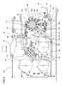
- the filter bag 1 - which forms the subject matter of a prior patent application filed by the Applicant (IT BO2002A000013) - is made from heat-sealable paper; has a portion 7 of thread which is wound around the outside of the containment chamber 2 and which is longer than the outline of the chamber, the excess length 8 of the thread being gathered and held between faces 9a, 9b of a pick-up tag 6; and is made by a machine, labelled 100, illustrated in its entirety in Figure 3.
- the machine 100 essentially comprises a structure including the following, arranged in suitable operating sequence, in a line extending from left to right in Figure 3 in which the production process is performed: a unit for preparing and feeding the materials used to make the filter bags 1, labelled 53 as a whole; an assembly for metering the infusion product, labelled 54 as a whole; a forming unit 55, a dividing unit 56 and a cutting unit 57.
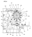
- the machine 100 Downstream of the cutting unit 57 and at a lower level - as shown in more detail in Figure 4 - the machine 100 comprises an apparatus 200 which forms the specific subject-matter of the present invention and which in turn comprises the following, arranged in operating sequence: means, labelled 123, 148 e 128, for manipulating the filter bags 1; means, labelled 60, 129 and 131, for forming the envelopes; the apparatus 200 being followed, finally, by a cartoning unit, labelled 61 as a whole.
- the envelope forming means 60 use a web 126 of packaging material - for example a heat-sealable paper - that is unwound from a roll 175 and fed along a straight, horizontal path 174.
- the web 126 moves through a series of folding transfer rollers 176 that make a longitudinal fold line 177 along the middle of it which divides the web 126 into two flaps 127 placed side by side and defining an interposed opening. This opening is accessible from the top down, that is to say, from the side of the web 126 and transversely to the feed path 174.
- the filter bag 1 manipulating means which, in a vertical plane of the machine 100, are located between the cutting unit 57 above and the packaging material web 126 below, comprise a pair of wheels 123, 128 which revolve in opposite directions about respective horizontal axes 124 and 178 and which are associated with the cutting unit 57 and with the packaging material web 126, respectively.
- the first wheel 123 is equipped with a series of operating units 148 designed: to retain the filter bags 1; to turn the placement plane of each about an axis 121 radial to the first wheel 123 and passing through each operating unit 148; and to transport the filter bags 1 along a first, circular arc shaped section 62a of their feed path along which the filter bags 1 move in a clockwise direction, with reference to Figure 4.
- the second wheel 128 is equipped with grippers and is located tangentially to the feed path 174 followed by the web 126 of packaging material.
- the second wheel 128 is designed: to receive the filter bags 1 one after the other from the first wheel 123; to transport them along a second circular arc shaped section 62b of their feed path; to place them between the flaps 127 of the web 126; and, on reaching an end section 62c that is centred relative to the flaps 127 and where the feed path of the filter bags 1 is substantially tangent to the feed path 174 of the web 126 and where the filter bags 1 move in the same direction as the web 126, to release them onto the web 126 itself.
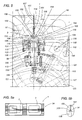
- Figures 5 and 6 show that the operating units 148 essentially comprise a folding unit 63 and a turning unit 58.
- the units 63 and 48 are designed to operate on the filter bags 1 which the first wheel 123 receives from the cutting unit 57 in an initial condition such that the filter bags 1 - as shown in the illustration in Figure 5a - has the shape of a length of flattened tube 34.
- the flattened tube 34 lies in a horizontal plane parallel to the axis of rotation 124 of the first wheel 123 and in such a way that the two pouches 3 of its containment chamber 2 are positioned one after the other, in line with each other and above one of the operating units 148 which in the meantime is passing by immediately downstream of the cutting unit 57.
- the folding units 63 and the turning units 58 are preferably combined in pairs to form a plurality of identical operating units 148, distributed at regular intervals around the edge of the first wheel 123.
- each operating unit 148 associated with the first wheel 123 essentially comprises: a device, labelled 105 as a whole, for clamping the lengths of tube 34; a system of grippers 106, pivotably mounted around horizontal axes 110; and revolving heads 149 that unitarily mount the clamping device 105 and the system of grippers 106 and that are driven rotationally about axes of rotation 121 which are radial relative to the first wheel 123.
- the device 105 for clamping the lengths of tube 34 comprises a pair of folding blades 107; a folding counterblade 108 and a pair of elastically opposing pressers 109 mounted on each side of the folding counterblade 108 in such a way that they can swing about the fixed axes 110 of the head 149 and designed to press against the sides of the counterblade 108 by elastic reaction.
- the folding blades 107 - see Figure 5b in particular - consist of two parallel thin flexible plates mounted on a revolving wheel 151 outside the first wheel 123.
- the folding counterblade 108 has a tapering end 150 and is mounted radially on the first wheel 123.
- the first wheel 123 also mounts the pressers 109 which press, by elastic reaction, against the tapering end 150 of the counterblade 108.
- the revolving wheel 151 mounting the folding blades 107 and the first wheel 123 are coupled in rolling relationship of relative primitive circles 152, 153, so that their phase-correlated rotation causes the folding blades 107 and the counterblade 108 to mesh with each other; this meshing occurring at the sealed join 5 between two contiguous pouches 3 of the interposed length of tube 34 constituting the filter bag 1. Thanks to this meshing, the sealed joins 5 of the lengths of tube fed in succession to the clamping device 105 are folded between the blades 107 and the counterblade 108 which confer the typical V shape at the bottom end 14 of the filter bag 1.
- the pressers 109 placed in elastically compliant contact against the sides of the counterblade 108, enable the folding blades 107 to move freely between them during the step of meshing with the counterblade 108.
- the blades 107 As the wheel 151 continues to rotate, the blades 107, having completed their folding action, are disengaged from the counterblade 108 and released from the lateral pressure exerted on them by the pressers 109, which now hold the filter bag 1 by the V-shaped fold.
- the grippers 106 - see also Figure 6 - include a pair of levers 116 which are rotatably coupled at one end to fixed pins 117, centred in the same axes of rotation 110 as the pressers 109 and which, at their opposite ends, have arms 118 designed to suitably interact with the lengths of tube 34 constituting the filter bags 1.
- the levers 116 are mounted crosswise and each is therefore connected to the pin 117 of the presser 109 on the side opposite to that where it operates.
- the levers 116 act in conjunction with the counterblade 108, with the pressers 109 and with suitably wide, fixed independent backs 154, in such manner as to support the lengths of tube 34 in the gripper 106 mounting wheel 123 in a substantially horizontal position and at three essentially aligned points.
- the bottom of the tube length constituting the filter bag is held by the counterblade 108 and by the pressers 109 while the pouches 3 of the containment chamber 2 are folded onto each other in a vertical position so that they lie in planes parallel to the axis of rotation 124 of the first gripper 106 mounting wheel 123.
- the filter bag 1 already held securely at the V-shaped fold at the bottom end 14, is also held by the top end 15 of the containment chamber 2 and kept in a position such that it lies in the same plane as a meridian plane of the gripper 106 mounting wheel 123, meaning by "meridian plane” a radial plane of the mounting wheel 123 containing the axis of rotation 124 of the wheel 123 itself.
- the opening and closing movement of the gripper 106 levers 116 is accomplished by an actuating device comprising two articulated pinions 114 also rotatably mounted on the pins 117 of the pressers 109.
- the pinions 114 are attached to the respective levers 116 and mesh with an interposed rack 113.
- a rod 112 slidable in a radial guide in the gripper 106 mounting wheel 123 imparts rotational drive simultaneously on the levers 116 in phase with the angle of rotation travelled by the gripper 106 mounting wheel 123, the sliding motion of the rod 112 being imparted by an actuating element 115, consisting of a cam 155 that comes into contact with the end of the rod 112 furthest away from the levers 116.
- Figure 5 shows that the operating units 148 comprise a platform 156 fixed to a tubular upright 119 supported by the first gripper 106 mounting wheel 123.
- the platform 156 supports the clamping device 105 and the grippers 106.
- the upright 119 which houses the rod 112 that actuates the rack 113 and the pinions 114 acting on the pressers 109 of the clamping device 105 and on the levers 116 of the grippers 106, is mounted in such a way that it can rotate about a radial axis 121 of the gripper 106 mounting wheel 123.
- the upright 119 is rotationally driven by actuator means 120 comprising linkages 122, equipped with ball joints, driven in coordinated phase with the angle of rotation described by the first gripper 106 mounting wheel 123.
- the linkages 122 impart to the platform 156 a rotational movement about the radial axis 121, which passes through the related operating unit 148, in such a way that the filter bags 1 are turned through 90° relative to the positions they had prior to being turned. Following this rotation, the filter bags 1 lie in planes parallel to the parallel planes 157 of the gripper 106 mounting wheel 123, meaning by "parallel planes" the planes transversal to the axis of rotation 124 of the first wheel 123 ( Figure 4).
- the operating units 148 are advantageously structured to enable the filter bags 1 to be folded and turned as they move, while the first gripper 106 mounting wheel 123 rotates continuously.
- the gripper 106 mounting wheel 123 is peripherally associated with a sealing unit 173 and a unit 59 for trimming the top ends 15 of the filter bags 1.
- the sealing unit 173 seals together the pouches 3 of the containment chambers 2 of the filter bags 1.
- the trimming unit 59 cuts the corners of the filter bag 1 top ends 15, conferring on the top end 15 of each filter bag 1 its characteristic trapezium shape.
- the apparatus 200 is equipped, as mentioned above, with a second gripper wheel 128 which is smaller in radius than the first wheel 123 and which rotates in the opposite direction.
- the peripheral speed of the second gripper wheel 128 is identical to the peripheral speed of the first gripper wheel 123. Further, the grippers on it are synchronised with the grippers 106 on the first wheel 123 so that the filter bags 1 are transferred from the operating units 148 on the first wheel 123 to the grippers on the second wheel 128 which pick them up by their top ends 15 protruding from the arms 118 of the grippers 106 on the first wheel 123 ( Figure 4).
- the filter bags 1 move in an anti-clockwise direction along the second section 62b of their feed path, and then, on reaching the end section 62c where their feed path is tangent to the feed path 174 of the web 126, the filter bags 1 are released by the grippers of the second wheel 128 between the flaps 127 of the envelope 51 paper web 126 at the desired minimum speed.
- the spacing of the filter bags 1 placed on the web 126 of envelope paper can be easily controlled by simply coordinating the feed speed of the web 126 of envelope paper with the peripheral speed of the second gripper wheel 128.
- the envelope forming means 60 comprise not only a heat-sealable paper feed station 125 equipped with a roll 175, but also a heat-sealing station 129 and a cutting unit 131.
- the heat-sealing station 129 seals the web 126 of envelope paper lengthways along the open top flaps 127 and then seals the flaps 127 to each other crossways in such a way as to form a continuous flattened tube 130 divided into a succession of separate chambers, each accommodating a filter bag 1.
- the cutting unit 131 then cuts the flattened tube 130 into lengths and sends the filter bags 1, each now wrapped in an envelope 51, to a cartoning unit 61 located downstream which places a collective packaging container 52 along the outfeed path of the filter bags, feeding it in such a way as to fill it according to predetermined filling patterns.
- the filter bags 1 fed downstream of the cutting unit 57 are turned in such a way that each filter bag 1 lies in a plane parallel to the first wheel 123. After being turned in this way, the filter bags 1 keep this position to the end of the production cycle, which, besides the formation of the envelopes 51, also includes cartoning the filter bags 1 wrapped in the envelopes 51.
Abstract
Description
- The present invention relates to the automatic production of filter bags, preferably of filter paper, containing products such as tea, camomile and similar herbs designed to be immersed in a liquid in order to make infusions for various uses, for example, as beverages or for diverse medicinal purposes.
- More specifically, the invention relates to an apparatus used in a continuous production process for automatically forming envelopes in which the filter bags containing the infusion product are accommodated, and which may if necessary, be sealed, for purposes of hygiene and in order to maintain the flavour and other characteristic properties of the infusion and/or to protect the filter bags themselves.
- In the automatic production of filter bags for infusion products, the preparation of the envelopes and the insertion of the filter bags into them are performed, as is known, by special devices or units which: process webs of envelope paper; fold them onto themselves; associate them with filter bags received from a filter bag making machine; and seal the paper webs to form a continuous succession of chambers, each containing a filter bag, which are then separated from each other and sent to a further packaging unit.
- In the process outlined above, the filter bags and the envelope paper web are fed along separate feed paths and the bags are associated with the web by intermittent, synchronised reciprocating movements at an area where their two paths intersect.
- This type of process cycle requires filter bag making machines and devices or machine stations which wrap the filter bags in the envelopes which are extremely complex and whose maximum production speed is limited also by the type of feed paths followed by the bags and paper web and by the intermittent, reciprocating motion of the components.
- The aim of the present invention is to overcome the above mentioned disadvantages by providing an apparatus in which the envelopes are formed and the filter bags associated with them according to continuous relative feed movements along feed paths which, in particular at the area where the filter bags are associated with the envelopes, are substantially parallel and run in the same direction.
- In accordance with the invention, the above aim is achieved by an apparatus for automatically and continuously forming envelopes to contain filter bags for an infusion product, characterised in that it comprises means for forming the envelopes, designed to make on a web of packaging material moving along a predetermined feed path a longitudinal fold line delimiting two adjacent flaps defining an interposed opening through which the web can be laterally accessed by the filter bags; manipulating means designed to receive the filter bags in succession, to turn them so that they lie in substantially the same plane as the web flaps and to move the filter bags along a feed path having at least one end section that is substantially centred relative to the web flaps, the filter bags moving along this end section in the same direction as the paper web, the manipulating means being designed to release the filter bags in such a way as to place them between the web flaps.
- An apparatus according to the invention can operate at much higher production speeds than the maximum speeds permitted by prior art devices used for the same purpose. This feature, besides being advantageous in itself, is also such as not to have a negative retroactive effect on the filter bag making machine, which means that the apparatus can operate in line in conjunction with the filter bag making machine to create a fully automatic installation working at very high production speeds.
- Thanks to the novel geometrical and kinematic arrangement of the feed paths of the filter bags and of the web of envelope material, and their continuous feed motion, the mechanical structure of the apparatus is much simpler, more reliable and economical than conventional apparatus used for the same purpose.
- Further, this geometrical and kinematic arrangement makes it possible to construct machines extending principally in a single plane, that is to say, in a vertical plane, which means that the machines occupy a small amount of space, especially in the direction orthogonal to said plane.
- The technical characteristics of the invention, with reference to the above aims, are clearly described in the claims below and its advantages are apparent from the detailed description which follows, with reference to the accompanying drawings which illustrate a preferred embodiment of the invention provided merely by way of example without restricting the scope of the inventive concept, and in which:
- Figures 1 and 2 are, respectively, front and side elevation views of a filter bag containing an infusion product and wrapped in an envelope;
- Figure 3 is a schematic, front assembly view of a filter bag making machine, shown in elevation, incorporating an apparatus according to the invention;
- Figure 4 is a partial front view illustrating an enlargement of a part of the apparatus of Figure 3 in greater detail;
- Figure 5 is a partial front view of a detail from Figure 4;
- Figure 5a is a plan view from above of a first detail from Figure 5;
- Figure 5b is a scaled-up view of another detail from Figure 5;
- Figure 6 is a side view of the detail of Figure 5.
- In Figures 1 and 2, the
numeral 1 denotes in its entirety a filter bag containing an infusion product, such as tea, camomile, or other herbal teas, having acontainment chamber 2 consisting of twoseparate pouches 3, each containing acharge 19 of the infusion product. Thefilter bag 1 is contained inside an overwrapping orenvelope 51, which encloses thefilter bag 1 and protects its contents in terms, for example, of hygiene, flavour, aroma and other characteristic properties. - The filter bag 1 - which forms the subject matter of a prior patent application filed by the Applicant (IT BO2002A000013) - is made from heat-sealable paper; has a
portion 7 of thread which is wound around the outside of thecontainment chamber 2 and which is longer than the outline of the chamber, theexcess length 8 of the thread being gathered and held betweenfaces up tag 6; and is made by a machine, labelled 100, illustrated in its entirety in Figure 3. - The
machine 100 essentially comprises a structure including the following, arranged in suitable operating sequence, in a line extending from left to right in Figure 3 in which the production process is performed: a unit for preparing and feeding the materials used to make thefilter bags 1, labelled 53 as a whole; an assembly for metering the infusion product, labelled 54 as a whole; a formingunit 55, a dividingunit 56 and acutting unit 57. - Downstream of the
cutting unit 57 and at a lower level - as shown in more detail in Figure 4 - themachine 100 comprises anapparatus 200 which forms the specific subject-matter of the present invention and which in turn comprises the following, arranged in operating sequence: means, labelled 123, 148e 128, for manipulating thefilter bags 1; means, labelled 60, 129 and 131, for forming the envelopes; theapparatus 200 being followed, finally, by a cartoning unit, labelled 61 as a whole. - As described in more detail below, the envelope forming means 60 use a
web 126 of packaging material - for example a heat-sealable paper - that is unwound from aroll 175 and fed along a straight,horizontal path 174. As it is unwound from theroll 175, theweb 126 moves through a series offolding transfer rollers 176 that make alongitudinal fold line 177 along the middle of it which divides theweb 126 into twoflaps 127 placed side by side and defining an interposed opening. This opening is accessible from the top down, that is to say, from the side of theweb 126 and transversely to thefeed path 174. - Looking in more detail with reference to Figure 4, the
filter bag 1 manipulating means, which, in a vertical plane of themachine 100, are located between thecutting unit 57 above and thepackaging material web 126 below, comprise a pair ofwheels horizontal axes cutting unit 57 and with thepackaging material web 126, respectively. - The
first wheel 123, the one with the larger diameter of the two, is equipped with a series ofoperating units 148 designed: to retain thefilter bags 1; to turn the placement plane of each about anaxis 121 radial to thefirst wheel 123 and passing through eachoperating unit 148; and to transport thefilter bags 1 along a first, circular arcshaped section 62a of their feed path along which thefilter bags 1 move in a clockwise direction, with reference to Figure 4. - The
second wheel 128 is equipped with grippers and is located tangentially to thefeed path 174 followed by theweb 126 of packaging material. Thesecond wheel 128 is designed: to receive thefilter bags 1 one after the other from thefirst wheel 123; to transport them along a second circular arcshaped section 62b of their feed path; to place them between theflaps 127 of theweb 126; and, on reaching anend section 62c that is centred relative to theflaps 127 and where the feed path of thefilter bags 1 is substantially tangent to thefeed path 174 of theweb 126 and where thefilter bags 1 move in the same direction as theweb 126, to release them onto theweb 126 itself. - Looking in more detail at the
operating units 148 of thefirst wheel 123, Figures 5 and 6 show that theoperating units 148 essentially comprise afolding unit 63 and aturning unit 58. - The
units 63 and 48 are designed to operate on thefilter bags 1 which thefirst wheel 123 receives from thecutting unit 57 in an initial condition such that the filter bags 1 - as shown in the illustration in Figure 5a - has the shape of a length offlattened tube 34. Theflattened tube 34 lies in a horizontal plane parallel to the axis ofrotation 124 of thefirst wheel 123 and in such a way that the twopouches 3 of itscontainment chamber 2 are positioned one after the other, in line with each other and above one of theoperating units 148 which in the meantime is passing by immediately downstream of thecutting unit 57. - The
folding units 63 and theturning units 58 are preferably combined in pairs to form a plurality ofidentical operating units 148, distributed at regular intervals around the edge of thefirst wheel 123. - As is more clearly discernible from Figures 5 and 6, each
operating unit 148 associated with thefirst wheel 123 essentially comprises: a device, labelled 105 as a whole, for clamping the lengths oftube 34; a system ofgrippers 106, pivotably mounted aroundhorizontal axes 110; and revolvingheads 149 that unitarily mount theclamping device 105 and the system ofgrippers 106 and that are driven rotationally about axes ofrotation 121 which are radial relative to thefirst wheel 123. - The
device 105 for clamping the lengths oftube 34 comprises a pair offolding blades 107; afolding counterblade 108 and a pair of elastically opposingpressers 109 mounted on each side of thefolding counterblade 108 in such a way that they can swing about thefixed axes 110 of thehead 149 and designed to press against the sides of thecounterblade 108 by elastic reaction. - The folding blades 107 - see Figure 5b in particular - consist of two parallel thin flexible plates mounted on a revolving
wheel 151 outside thefirst wheel 123. Thefolding counterblade 108 has a taperingend 150 and is mounted radially on thefirst wheel 123. - The
first wheel 123 also mounts thepressers 109 which press, by elastic reaction, against the taperingend 150 of thecounterblade 108. - The revolving
wheel 151 mounting thefolding blades 107 and thefirst wheel 123 are coupled in rolling relationship of relativeprimitive circles folding blades 107 and thecounterblade 108 to mesh with each other; this meshing occurring at thesealed join 5 between twocontiguous pouches 3 of the interposed length oftube 34 constituting thefilter bag 1. Thanks to this meshing, the sealed joins 5 of the lengths of tube fed in succession to theclamping device 105 are folded between theblades 107 and thecounterblade 108 which confer the typical V shape at thebottom end 14 of thefilter bag 1. - As can also be discerned from Figure 5, the
pressers 109, placed in elastically compliant contact against the sides of thecounterblade 108, enable thefolding blades 107 to move freely between them during the step of meshing with thecounterblade 108. As thewheel 151 continues to rotate, theblades 107, having completed their folding action, are disengaged from thecounterblade 108 and released from the lateral pressure exerted on them by thepressers 109, which now hold thefilter bag 1 by the V-shaped fold. - The grippers 106 - see also Figure 6 - include a pair of
levers 116 which are rotatably coupled at one end to fixedpins 117, centred in the same axes ofrotation 110 as thepressers 109 and which, at their opposite ends, havearms 118 designed to suitably interact with the lengths oftube 34 constituting thefilter bags 1. - The
levers 116 are mounted crosswise and each is therefore connected to thepin 117 of thepresser 109 on the side opposite to that where it operates. Thelevers 116 act in conjunction with thecounterblade 108, with thepressers 109 and with suitably wide, fixedindependent backs 154, in such manner as to support the lengths oftube 34 in thegripper 106mounting wheel 123 in a substantially horizontal position and at three essentially aligned points. - When the
levers 116 are tightened, the bottom of the tube length constituting the filter bag is held by thecounterblade 108 and by thepressers 109 while thepouches 3 of thecontainment chamber 2 are folded onto each other in a vertical position so that they lie in planes parallel to the axis ofrotation 124 of thefirst gripper 106mounting wheel 123. - In other words, the
filter bag 1, already held securely at the V-shaped fold at thebottom end 14, is also held by thetop end 15 of thecontainment chamber 2 and kept in a position such that it lies in the same plane as a meridian plane of thegripper 106mounting wheel 123, meaning by "meridian plane" a radial plane of themounting wheel 123 containing the axis ofrotation 124 of thewheel 123 itself. - The opening and closing movement of the
gripper 106levers 116 is accomplished by an actuating device comprising two articulatedpinions 114 also rotatably mounted on thepins 117 of thepressers 109. - The
pinions 114 are attached to therespective levers 116 and mesh with an interposedrack 113. - A
rod 112 slidable in a radial guide in thegripper 106mounting wheel 123 imparts rotational drive simultaneously on thelevers 116 in phase with the angle of rotation travelled by thegripper 106mounting wheel 123, the sliding motion of therod 112 being imparted by an actuatingelement 115, consisting of acam 155 that comes into contact with the end of therod 112 furthest away from thelevers 116. - As to the rotation of the
filter bags 1 about theirlongitudinal axes 50, that is to say, about aradial axis 121 of the firstgripper mounting wheel 123, Figure 5 shows that theoperating units 148 comprise aplatform 156 fixed to a tubular upright 119 supported by thefirst gripper 106mounting wheel 123. - The
platform 156 supports theclamping device 105 and thegrippers 106. - The upright 119, which houses the
rod 112 that actuates therack 113 and thepinions 114 acting on thepressers 109 of theclamping device 105 and on thelevers 116 of thegrippers 106, is mounted in such a way that it can rotate about aradial axis 121 of thegripper 106mounting wheel 123. - The upright 119 is rotationally driven by actuator means 120 comprising
linkages 122, equipped with ball joints, driven in coordinated phase with the angle of rotation described by thefirst gripper 106mounting wheel 123. - The
linkages 122 impart to the platform 156 a rotational movement about theradial axis 121, which passes through therelated operating unit 148, in such a way that thefilter bags 1 are turned through 90° relative to the positions they had prior to being turned. Following this rotation, thefilter bags 1 lie in planes parallel to theparallel planes 157 of thegripper 106mounting wheel 123, meaning by "parallel planes" the planes transversal to the axis ofrotation 124 of the first wheel 123 (Figure 4). - It should be noticed that the
operating units 148 are advantageously structured to enable thefilter bags 1 to be folded and turned as they move, while thefirst gripper 106mounting wheel 123 rotates continuously. - The
gripper 106mounting wheel 123 is peripherally associated with asealing unit 173 and aunit 59 for trimming thetop ends 15 of thefilter bags 1. - The
sealing unit 173 seals together thepouches 3 of thecontainment chambers 2 of thefilter bags 1. Thetrimming unit 59 cuts the corners of thefilter bag 1top ends 15, conferring on thetop end 15 of eachfilter bag 1 its characteristic trapezium shape. - It should be noticed that the sealing of the
top ends 15 and the trimming of thecorners 23 are performed on the portions of thefilter bag 1top ends 15 which - as shown in Figure 6 - protrude from thearms 118 of thelevers 116 and project radially from the edge of thefirst wheel 123. These operations, since they are performed after thefilter bags 1 have been turned so that they lie in planes parallel to a parallel plane of thefirst wheel 123, occur quickly and easily and do not require thegripper 106mounting wheel 123 to be slowed down or stopped. - Between the
first gripper 106mounting wheel 123 and the envelope forming means, labelled 60 in their entirety, theapparatus 200 is equipped, as mentioned above, with asecond gripper wheel 128 which is smaller in radius than thefirst wheel 123 and which rotates in the opposite direction. - The peripheral speed of the
second gripper wheel 128 is identical to the peripheral speed of thefirst gripper wheel 123. Further, the grippers on it are synchronised with thegrippers 106 on thefirst wheel 123 so that thefilter bags 1 are transferred from the operatingunits 148 on thefirst wheel 123 to the grippers on thesecond wheel 128 which pick them up by their top ends 15 protruding from thearms 118 of thegrippers 106 on the first wheel 123 (Figure 4). Held in this way, thefilter bags 1 move in an anti-clockwise direction along thesecond section 62b of their feed path, and then, on reaching theend section 62c where their feed path is tangent to thefeed path 174 of theweb 126, thefilter bags 1 are released by the grippers of thesecond wheel 128 between theflaps 127 of theenvelope 51paper web 126 at the desired minimum speed. - It should be noticed that the spacing of the
filter bags 1 placed on theweb 126 of envelope paper can be easily controlled by simply coordinating the feed speed of theweb 126 of envelope paper with the peripheral speed of thesecond gripper wheel 128. - The envelope forming means 60 comprise not only a heat-sealable paper feed station 125 equipped with a
roll 175, but also a heat-sealingstation 129 and acutting unit 131. - The heat-sealing
station 129 seals theweb 126 of envelope paper lengthways along the opentop flaps 127 and then seals theflaps 127 to each other crossways in such a way as to form a continuous flattenedtube 130 divided into a succession of separate chambers, each accommodating afilter bag 1. - The
cutting unit 131 then cuts the flattenedtube 130 into lengths and sends thefilter bags 1, each now wrapped in anenvelope 51, to acartoning unit 61 located downstream which places acollective packaging container 52 along the outfeed path of the filter bags, feeding it in such a way as to fill it according to predetermined filling patterns. - The invention described above optimises the entire production cycle, thereby fully achieving the above mentioned aims. In the optimised production cycle embodied by the apparatus according to the invention, the
filter bags 1 fed downstream of the cuttingunit 57 are turned in such a way that eachfilter bag 1 lies in a plane parallel to thefirst wheel 123. After being turned in this way, thefilter bags 1 keep this position to the end of the production cycle, which, besides the formation of theenvelopes 51, also includes cartoning thefilter bags 1 wrapped in theenvelopes 51. - It will be understood that the invention described may be useful in many industrial applications and may be modified and adapted in several ways without thereby departing from the scope of the inventive concept. Moreover, all the details of the invention may be substituted by technically equivalent elements.
Claims (20)
- An apparatus for automatically and continuously forming envelopes (51) to contain filter bags (1) for an infusion product, characterised in that it comprises means (60; 129, 131) for forming the envelopes, designed to make on a web (126) of packaging material moving along a predetermined feed path (174) a longitudinal fold line delimiting two adjacent flaps (127) defining an interposed opening through which the web (126) can be laterally accessed by the filter bags (1); manipulating means (123, 148, 128) designed to receive the filter bags (1) in succession, to turn them so that they lie in substantially the same plane as the flaps (127) of the web (126) and to move the filter bags (1) along a feed path (62a, 62b, 62c) having at least one end section (62c) that is substantially centred relative to the web flaps (127), the filter bags (1) moving along this end section (62c) in the same direction as the paper web (126), the manipulating means being designed to release the filter bags (1) in such a way as to place them between the flaps (127) of the web (126).
- The apparatus according to claim 1, characterised in that the means for manipulating the filter bags (1) comprise a first wheel (123) which rotates about a horizontal axis of rotation (124) and which is equipped with operating units (148) designed to retain the filter bags (1); to turn the placement plane of each about an axis (121) radial to the first wheel (123) and to transport the filter bags (1) along a first, arc shaped section (62a) of their feed path; the manipulating means also comprising a second gripper wheel (128) peripherally associated with the first wheel (123), rotating in the opposite direction and tangential to the feed path (174) of the web of packaging material, the second gripper wheel (128) being designed to receive the filter bags (1) one after the other from the first wheel (123), to transport them along a second arc shaped section (62b) of their feed path, to place them between the flaps (127) of the web (126) and to release them onto the web (126) itself.
- The machine according to claim 1 or 2, characterised in that the web (126) of packaging material has on it a layer of glue to be thermally activated, the means for forming the envelopes (51) including a heat-sealing station (129) where the web (126) of envelope material passing through with the filter bags (1) placed between its flaps (127) is sealed in such a way as to form a continuous flattened tube (130) divided into a succession of separate chambers, each accommodating a filter bag (1).
- The machine according to claim 3, characterised in that the envelope (51) forming means comprise a cutting unit (131) designed to cut the flattened tube (130) into successive lengths corresponding to the envelopes (51).
- The apparatus according to any of the foregoing claims, characterised in that the filter bags (1) have containment chambers (2) each consisting of two contiguous pouches (3) located one after the other, the operating units (148) of the first wheel (123) being equipped with a unit (63) for folding the pouches (3) of the filter bags (1) and with a unit (58) for turning the filter bags (1), these two units being combined with each other, the folding unit (63) being designed to fold the containment chamber (2) until the pouches (3) are mutually superposed, and the turning unit (58) being designed to turn the filter bags (1) about their longitudinal axes (50) so as to rotate the plane in which each filter bag (1) lies relative to the axis of rotation (124) of the first revolving wheel (123).
- The apparatus according to claim 5, characterised in that the folding unit (63) comprises a device (105) for clamping the infusion product containment chamber (2) of the filter bag (1) and a system of grippers (106), pivotably mounted around horizontal axes (110), the clamping device (105) being designed to hold the containment chamber (2) by the sealed join (5) connecting its two contiguous pouches (3), the system of grippers (106) being designed to fold the containment chamber (2) pouches (3), initially lying flat, one after the other, onto each other until the pouches (3) are mutually superposed.
- The apparatus according to claim 6, characterised in that the clamping device (105), while it holds the filter bag (1), also makes a fold in the bottom sealed join (5) which connects the pouches (3).
- The apparatus according to claim 7, characterised in that the clamping and folding device (105) comprises a pair of folding blades (107) and a folding counterblade (108) on opposite sides of the filter bag (1) and pressing against each other in such a way as to make a fold in the bottom sealed join (5) between two pouches (3); pressers (109) being provided, one on each side of the folding counterblade (108), which elastically oppose each other to allow the folding blades (107) to pass freely between them and the counterblade (108) when the folding blades (107) and the counterblade (108) move towards each other, and, instead, to securely hold the bottom fold in the filter bag (1) by pressing it against the counterblade (108) when the folding blades (107) move away from the counterblade (108).
- The apparatus according to claim 8, characterised in that the folding blades 107 and the counterblade (108) are mounted on a revolving wheel (151) and on the first gripper wheel (123), which are coupled in rolling relationship of relative primitive circles (152, 153) in such a way that the folding blades (107) and the counterblade (108) mesh with each other.
- The apparatus according to claim 8, characterised in that the pressers (109) are mounted in such a way that they can swing about respective horizontal axes (110).
- The apparatus according to claim 6, characterised in that each gripper (106) includes a pair of levers (116) which are rotatably mounted on fixed pins (117), the levers (116) opening and closing in such a way as to make the pouches (3) of the filter bag (1) rotate about the common sealed join (5) until they are mutually superposed.
- The apparatus according to claim 11, characterised in that the levers (116) are mounted crosswise.
- The apparatus according to claim 11, characterised in that the levers (116) have specially shaped ends (118) designed to interact with each other and to grip the filter bag (1) close to its top end (15) as soon as the pouches (3) of the filter bag (1) are folded onto each other.
- The apparatus according to any of the foregoing claims from 5 to 13, characterised in that the folding unit (63) comprises a device (111) for actuating the levers (116) equipped with a rack (113) mounted on a slidable rod (112) and rotatable pinions (114) which mesh with the rack (113) and which are attached to the levers (116), the sliding motion imparted on the rod (112) by an actuating element (115) in a first direction of rotation of the levers (116) causing the filter bag (1) to be folded in such a way as to superpose the pouches (3) of the containment chamber (2), and to be held by its top end (15), the sliding motion in the opposite direction placing the levers (116) in a condition in which they are ready to receive a filter bag (1) with the containment chamber (2) pouches (3) positioned in line.
- The apparatus according to claim 14, characterised in that the actuating element (115) comprises a cam (155) associated with the slidable rod (112).
- The apparatus according to claim 5, characterised in that the turning unit (58) comprises a head (149) that revolves about an axis (121) radial to the first gripper mounting wheel (123), means (120) for rotationally actuating the head (149) in synchrony with the rotation of the first wheel (123) causing the folding unit (58) to rotate in such a way as to turn the filter bag (1) so that the plane which it finally lies in is transversal to the axis of rotation (124) of the first wheel (123).
- The apparatus according to claim 16, characterised in that the means (120) for rotationally actuating the head (149) comprise linkages (122) driven by mechanical cams in synchrony with the rotation of the first gripper wheel (123).
- The apparatus according to claim 2, characterised in that it comprises a unit (59), which is associated with the edge of the first wheel (123) and which is designed to trim the top end (15) of the filter bag (1) projecting radially from the edge of the first wheel (123).
- The apparatus according to claim 18, characterised in that the second gripper wheel (128) is designed to grip the filter bags (1) by their top ends (15) projecting radially from the edge of the first wheel (123).
- The apparatus according to claim 2, characterised in that it comprises a unit (173), which is associated with the edge of the first wheel (123) and which is designed to seal the top end (15) of the filter bag (1) projecting radially from the edge of the first wheel (123).
Applications Claiming Priority (2)
| Application Number | Priority Date | Filing Date | Title |
|---|---|---|---|
| ITBO20020479 | 2002-07-23 | ||
| IT2002BO000479A ITBO20020479A1 (en) | 2002-07-23 | 2002-07-23 | APPARATUS FOR FORMING AUTOMATICALLY, WITH A CONTINUOUS PROCESS, COVERS FOR CONTAINING FILTER BAGS CONTAINING A SUBSTANCE IN THEIR TIME |
Publications (2)
| Publication Number | Publication Date |
|---|---|
| EP1384664A1 true EP1384664A1 (en) | 2004-01-28 |
| EP1384664B1 EP1384664B1 (en) | 2006-01-04 |
Family
ID=11440324
Family Applications (1)
| Application Number | Title | Priority Date | Filing Date |
|---|---|---|---|
| EP03425472A Expired - Lifetime EP1384664B1 (en) | 2002-07-23 | 2003-07-15 | Apparatus for automatically and continuously forming envelopes containing filter bags for infusion products |
Country Status (7)
| Country | Link |
|---|---|
| US (1) | US6837024B1 (en) |
| EP (1) | EP1384664B1 (en) |
| CN (1) | CN1301881C (en) |
| AT (1) | ATE314965T1 (en) |
| DE (1) | DE60303112T2 (en) |
| ES (1) | ES2255665T3 (en) |
| IT (1) | ITBO20020479A1 (en) |
Cited By (8)
| Publication number | Priority date | Publication date | Assignee | Title |
|---|---|---|---|---|
| WO2013117310A1 (en) | 2012-02-06 | 2013-08-15 | Tecnomeccanica S.R.L. | Compacting and transfer device of groups of filter bags containing infusion substances |
| CN105691730A (en) * | 2016-04-21 | 2016-06-22 | 瑞安市瑞志机械有限公司 | Bag-in-bag packing equipment |
| CN105691777A (en) * | 2016-04-21 | 2016-06-22 | 瑞安市瑞志机械有限公司 | Bag-in-bag packaging equipment |
| ITUB20161017A1 (en) * | 2016-02-24 | 2017-08-24 | Ima Spa | MACHINE FOR FORMING BAGS-FILTERS FOR INFUSION PRODUCTS. |
| IT201700074573A1 (en) * | 2017-07-04 | 2019-01-04 | Ima Spa | MACHINE FOR BAGS FORMATION - FILTER FOR INFUSION PRODUCTS. |
| EP3733384A1 (en) * | 2019-05-02 | 2020-11-04 | Teepack Spezialmaschinen GmbH & Co. KG | Device and method for transporting finished and filled tubular pieces |
| IT202000004321A1 (en) * | 2020-03-02 | 2021-09-02 | Ima Spa | MACHINE FOR FORMING BAGS WITH INFUSION OR EXTRACTION PRODUCTS. |
| US11708184B2 (en) | 2020-08-31 | 2023-07-25 | Teepack Spezialmaschinen Gmbh & Co. Kg | Device for manufacturing a pouch accommodated in a wrapping |
Families Citing this family (8)
| Publication number | Priority date | Publication date | Assignee | Title |
|---|---|---|---|---|
| ITBO20060094A1 (en) * | 2006-02-10 | 2007-08-11 | Tecnomeccanica Srl | METHOD AND A HIGH SPEED PACKAGING LINE OF ENVELOPES FILTER CONTAINING AN INFUSION SUBSTANCE |
| US20080078770A1 (en) * | 2006-10-02 | 2008-04-03 | Eric Thomas | Insulated package insert apparatus and method |
| IT1394271B1 (en) * | 2009-05-25 | 2012-06-06 | Ima Flavour S R L Ora Ima Ind S R L | COMPRESSION GROUP - ENGRAVING - ROLLER CUTTING |
| WO2016029987A1 (en) * | 2014-08-28 | 2016-03-03 | Azionaria Costruzioni Macchine Automatiche | Apparatus for producing packages of infusion products |
| ITUA20164461A1 (en) * | 2016-06-17 | 2017-12-17 | I M A Industria Macch Automatiche S P A In Sigla Ima S P A | DOSING DEVICE FOR FEEDING INFUSION PRODUCTS. |
| IT201600101450A1 (en) * | 2016-10-10 | 2018-04-10 | Gima Tt S P A | MACHINE AND METHOD FOR REALIZING ARTICLES IN CAPSULE |
| IT201600128479A1 (en) * | 2016-12-20 | 2018-06-20 | Ima Spa | MACHINE FOR BAGS FORMATION - FILTER FOR INFUSION PRODUCTS. |
| IT201700123953A1 (en) * | 2017-10-31 | 2019-05-01 | Ima Spa | Filter bag forming machine for infusion products. |
Citations (2)
| Publication number | Priority date | Publication date | Assignee | Title |
|---|---|---|---|---|
| US4078356A (en) * | 1976-11-03 | 1978-03-14 | Morning Treat Coffee Company, Inc. | Packaging method and apparatus for ground coffee or the like |
| WO1999065772A1 (en) * | 1998-06-19 | 1999-12-23 | Tetley Gb Limited | Method and apparatus for packaging discrete articles |
Family Cites Families (11)
| Publication number | Priority date | Publication date | Assignee | Title |
|---|---|---|---|---|
| US2362459A (en) * | 1942-02-07 | 1944-11-14 | Nat Urn Bag Co Inc | Infusion package and the manufacture thereof |
| US4261680A (en) * | 1979-06-06 | 1981-04-14 | Carnley F Paul | Apparatus for orienting articles having an enlarged end |
| IT1202155B (en) * | 1985-06-28 | 1989-02-02 | Ima Spa | IMPROVEMENT OF MACHINES FOR THE PRODUCTION OF BAGS-FILTER FOR INFUSION PRODUCTS AND THEIR SINGLE PACKAGING IN AN EXTERNAL ENCLOSURE |
| IT1207631B (en) * | 1987-03-09 | 1989-05-25 | Cestind Centro Studi Ind | EQUIPMENT FOR THE PACKAGING OF SINGLE-PURPOSE FILTER BAGS IN BAGS IN CONTINUOUS PACKAGING MACHINES FOR FILTER BAGS |
| NL9500496A (en) * | 1995-03-13 | 1996-10-01 | Food Processing Systems | Device for directing eggs to a second conveyor with the tip to one side. |
| IT1282482B1 (en) * | 1995-04-04 | 1998-03-23 | Tecnomeccanica Srl | METHOD FOR FOLDING A TUBULAR SHEET OF PAPER-FILTER WITH AN ELONGATED SHAPE CONTAINING AN INFUSION PRODUCT. ARRANGED THERE |
| IT1293236B1 (en) * | 1997-07-09 | 1999-02-16 | Gd Spa | METHOD AND UNIT FEEDING OF COLLARS FOR RIGID CIGARETTES PACKAGES TO A CONTINUOUS PACKAGING LINE. |
| DE19827133A1 (en) * | 1998-06-18 | 1999-12-23 | Volkswagen Ag | Powertrain management for a motor vehicle |
| IT1305534B1 (en) * | 1998-09-18 | 2001-05-09 | Ima Spa | MACHINE PERFECTED FOR THE PACKAGING OF FILTER BAGS CONTAINING AN INFUSION PRODUCT PROVIDED WITH A TAKE-OFF LABEL |
| PT1122169E (en) * | 2000-01-31 | 2004-04-30 | Tetra Laval Holdings & Finance | DEVICE FOR ADJUSTING THE CROSS POSITION OF A TAPE OF PACKING MATERIAL |
| IT1320887B1 (en) * | 2000-02-22 | 2003-12-10 | Ima Spa | METHOD FOR PACKAGING BAGS - FILTER FOR INFUSION PRODUCTS IN RELATED CLOSED OVER-WRAPS AND RELEVANT IMPLEMENTING MACHINE |
-
2002
- 2002-07-23 IT IT2002BO000479A patent/ITBO20020479A1/en unknown
-
2003
- 2003-07-15 DE DE60303112T patent/DE60303112T2/en not_active Expired - Lifetime
- 2003-07-15 EP EP03425472A patent/EP1384664B1/en not_active Expired - Lifetime
- 2003-07-15 ES ES03425472T patent/ES2255665T3/en not_active Expired - Lifetime
- 2003-07-15 AT AT03425472T patent/ATE314965T1/en not_active IP Right Cessation
- 2003-07-22 CN CNB03132861XA patent/CN1301881C/en not_active Expired - Fee Related
- 2003-07-22 US US10/624,197 patent/US6837024B1/en not_active Expired - Fee Related
Patent Citations (2)
| Publication number | Priority date | Publication date | Assignee | Title |
|---|---|---|---|---|
| US4078356A (en) * | 1976-11-03 | 1978-03-14 | Morning Treat Coffee Company, Inc. | Packaging method and apparatus for ground coffee or the like |
| WO1999065772A1 (en) * | 1998-06-19 | 1999-12-23 | Tetley Gb Limited | Method and apparatus for packaging discrete articles |
Cited By (18)
| Publication number | Priority date | Publication date | Assignee | Title |
|---|---|---|---|---|
| WO2013117310A1 (en) | 2012-02-06 | 2013-08-15 | Tecnomeccanica S.R.L. | Compacting and transfer device of groups of filter bags containing infusion substances |
| JP2019509945A (en) * | 2016-02-24 | 2019-04-11 | イ.エンメ.ア.インドゥストリア マッキーネ アウトマティケ ソチエタ ペル アツィオニ | Machine forming filter bag for extraction products |
| ITUB20161017A1 (en) * | 2016-02-24 | 2017-08-24 | Ima Spa | MACHINE FOR FORMING BAGS-FILTERS FOR INFUSION PRODUCTS. |
| WO2017145044A1 (en) * | 2016-02-24 | 2017-08-31 | I.M.A. Industria Macchine Automatiche S.P.A. | Machine for forming filter bags for infusion products. |
| US10793347B2 (en) | 2016-02-24 | 2020-10-06 | I.M.A. Industria Macchine Automatiche S.P.A. | Machine for forming filter bags for infusion products |
| CN105691730A (en) * | 2016-04-21 | 2016-06-22 | 瑞安市瑞志机械有限公司 | Bag-in-bag packing equipment |
| CN105691777A (en) * | 2016-04-21 | 2016-06-22 | 瑞安市瑞志机械有限公司 | Bag-in-bag packaging equipment |
| CN105691730B (en) * | 2016-04-21 | 2018-02-16 | 浙江瑞志机械有限公司 | Bag in bag packaging facilities |
| CN105691777B (en) * | 2016-04-21 | 2018-02-16 | 浙江瑞志机械有限公司 | A kind of bag in bag packaging facilities |
| WO2019007924A1 (en) * | 2017-07-04 | 2019-01-10 | I.M.A. Industria Macchine Automatiche S.P.A. | Machine for making filter bags for infusion products |
| IT201700074573A1 (en) * | 2017-07-04 | 2019-01-04 | Ima Spa | MACHINE FOR BAGS FORMATION - FILTER FOR INFUSION PRODUCTS. |
| US11186395B2 (en) | 2017-07-04 | 2021-11-30 | I.M.A. Industria Macchine Automatiche S.P.A. | Machine for making filter bags for infusion products |
| EP3733384A1 (en) * | 2019-05-02 | 2020-11-04 | Teepack Spezialmaschinen GmbH & Co. KG | Device and method for transporting finished and filled tubular pieces |
| US11299304B2 (en) | 2019-05-02 | 2022-04-12 | Teepack Spezialmaschinen Gmbh & Co. Kg | Device and method for transporting ready-cut and filled hose pieces |
| US11685561B2 (en) | 2019-05-02 | 2023-06-27 | Teepack Spezialmaschinen Gmbh & Co. Kg | Device and method for making a pouch provided with a wrapping and containing a brewable material |
| IT202000004321A1 (en) * | 2020-03-02 | 2021-09-02 | Ima Spa | MACHINE FOR FORMING BAGS WITH INFUSION OR EXTRACTION PRODUCTS. |
| WO2021176321A1 (en) * | 2020-03-02 | 2021-09-10 | I.M.A. Industria Macchine Automatiche S.P.A. | Machine for forming bags with infusion or extraction products |
| US11708184B2 (en) | 2020-08-31 | 2023-07-25 | Teepack Spezialmaschinen Gmbh & Co. Kg | Device for manufacturing a pouch accommodated in a wrapping |
Also Published As
| Publication number | Publication date |
|---|---|
| DE60303112T2 (en) | 2006-08-03 |
| EP1384664B1 (en) | 2006-01-04 |
| ITBO20020479A0 (en) | 2002-07-23 |
| CN1301881C (en) | 2007-02-28 |
| CN1483647A (en) | 2004-03-24 |
| DE60303112D1 (en) | 2006-03-30 |
| ATE314965T1 (en) | 2006-02-15 |
| US6837024B1 (en) | 2005-01-04 |
| ES2255665T3 (en) | 2006-07-01 |
| ITBO20020479A1 (en) | 2004-01-23 |
Similar Documents
| Publication | Publication Date | Title |
|---|---|---|
| EP1384664B1 (en) | Apparatus for automatically and continuously forming envelopes containing filter bags for infusion products | |
| EP1384665B1 (en) | Machine for making an infusion bag with a gathered thread attached to the tag | |
| EP2681119B1 (en) | Machine for producing filter bags with products for infusion and with an outer wrapper envelope | |
| EP2483163B1 (en) | Method and machine for packing infusion products into capsules | |
| JP5684721B2 (en) | Apparatus for manufacturing filter bags for soaking products and packaging the filter bags with outer packaging | |
| EP2483160B1 (en) | Machine for packing infusion products into capsules and featuring sealing unit | |
| AU2001294403B8 (en) | Method and device for packaging a food product, such as a candy, as well as a packaged candy | |
| EP1818264B1 (en) | A method and line for the high-speed packaging of filter bags containing an infusion product. | |
| CN111295338B (en) | Machine for forming filter bags for infusion products | |
| JP5432219B2 (en) | Method and apparatus for producing small packets | |
| WO2011039707A1 (en) | Machine for packing infusion products into capsules | |
| EP3222533A1 (en) | Packaging machine and wrapping method for the production of a pack of tobacco articles | |
| EP1384666B1 (en) | An apparatus for preparing and feeding the materials used to make a filter bag for infusion products. | |
| EP3222536B1 (en) | Packaging machine and wrapping method for the production of a pack of tobacco articles | |
| EP3222535B1 (en) | Packaging machine and wrapping method for the production of a pack of tobacco articles | |
| EP3222534B1 (en) | Packaging machine and wrapping method for the production of a pack of tobacco articles | |
| EP3222537B1 (en) | Packaging machine and wrapping method for the production of a pack of tobacco articles | |
| SU411002A1 (en) | ||
| EP3649051A1 (en) | Machine for making filter bags for infusion products | |
| MXPA99010547A (en) | An apparatus for applying drinking straws |
Legal Events
| Date | Code | Title | Description |
|---|---|---|---|
| PUAI | Public reference made under article 153(3) epc to a published international application that has entered the european phase |
Free format text: ORIGINAL CODE: 0009012 |
|
| AK | Designated contracting states |
Kind code of ref document: A1 Designated state(s): AT BE BG CH CY CZ DE DK EE ES FI FR GB GR HU IE IT LI LU MC NL PT RO SE SI SK TR |
|
| AX | Request for extension of the european patent |
Extension state: AL LT LV MK |
|
| 17P | Request for examination filed |
Effective date: 20031223 |
|
| 17Q | First examination report despatched |
Effective date: 20040504 |
|
| AKX | Designation fees paid |
Designated state(s): AT BE BG CH CY CZ DE DK EE ES FI FR GB GR HU IE IT LI LU MC NL PT RO SE SI SK TR |
|
| GRAP | Despatch of communication of intention to grant a patent |
Free format text: ORIGINAL CODE: EPIDOSNIGR1 |
|
| GRAS | Grant fee paid |
Free format text: ORIGINAL CODE: EPIDOSNIGR3 |
|
| GRAA | (expected) grant |
Free format text: ORIGINAL CODE: 0009210 |
|
| AK | Designated contracting states |
Kind code of ref document: B1 Designated state(s): AT BE BG CH CY CZ DE DK EE ES FI FR GB GR HU IE IT LI LU MC NL PT RO SE SI SK TR |
|
| PG25 | Lapsed in a contracting state [announced via postgrant information from national office to epo] |
Ref country code: AT Free format text: LAPSE BECAUSE OF FAILURE TO SUBMIT A TRANSLATION OF THE DESCRIPTION OR TO PAY THE FEE WITHIN THE PRESCRIBED TIME-LIMIT Effective date: 20060104 Ref country code: SI Free format text: LAPSE BECAUSE OF FAILURE TO SUBMIT A TRANSLATION OF THE DESCRIPTION OR TO PAY THE FEE WITHIN THE PRESCRIBED TIME-LIMIT Effective date: 20060104 Ref country code: FI Free format text: LAPSE BECAUSE OF FAILURE TO SUBMIT A TRANSLATION OF THE DESCRIPTION OR TO PAY THE FEE WITHIN THE PRESCRIBED TIME-LIMIT Effective date: 20060104 Ref country code: NL Free format text: LAPSE BECAUSE OF FAILURE TO SUBMIT A TRANSLATION OF THE DESCRIPTION OR TO PAY THE FEE WITHIN THE PRESCRIBED TIME-LIMIT Effective date: 20060104 Ref country code: RO Free format text: LAPSE BECAUSE OF FAILURE TO SUBMIT A TRANSLATION OF THE DESCRIPTION OR TO PAY THE FEE WITHIN THE PRESCRIBED TIME-LIMIT Effective date: 20060104 Ref country code: BE Free format text: LAPSE BECAUSE OF FAILURE TO SUBMIT A TRANSLATION OF THE DESCRIPTION OR TO PAY THE FEE WITHIN THE PRESCRIBED TIME-LIMIT Effective date: 20060104 Ref country code: SK Free format text: LAPSE BECAUSE OF FAILURE TO SUBMIT A TRANSLATION OF THE DESCRIPTION OR TO PAY THE FEE WITHIN THE PRESCRIBED TIME-LIMIT Effective date: 20060104 |
|
| REG | Reference to a national code |
Ref country code: GB Ref legal event code: FG4D |
|
| REG | Reference to a national code |
Ref country code: CH Ref legal event code: EP |
|
| REG | Reference to a national code |
Ref country code: IE Ref legal event code: FG4D |
|
| REG | Reference to a national code |
Ref country code: CH Ref legal event code: NV Representative=s name: ISLER & PEDRAZZINI AG |
|
| REF | Corresponds to: |
Ref document number: 60303112 Country of ref document: DE Date of ref document: 20060330 Kind code of ref document: P |
|
| PG25 | Lapsed in a contracting state [announced via postgrant information from national office to epo] |
Ref country code: BG Free format text: LAPSE BECAUSE OF FAILURE TO SUBMIT A TRANSLATION OF THE DESCRIPTION OR TO PAY THE FEE WITHIN THE PRESCRIBED TIME-LIMIT Effective date: 20060404 Ref country code: DK Free format text: LAPSE BECAUSE OF FAILURE TO SUBMIT A TRANSLATION OF THE DESCRIPTION OR TO PAY THE FEE WITHIN THE PRESCRIBED TIME-LIMIT Effective date: 20060404 Ref country code: SE Free format text: LAPSE BECAUSE OF FAILURE TO SUBMIT A TRANSLATION OF THE DESCRIPTION OR TO PAY THE FEE WITHIN THE PRESCRIBED TIME-LIMIT Effective date: 20060404 |
|
| PG25 | Lapsed in a contracting state [announced via postgrant information from national office to epo] |
Ref country code: PT Free format text: LAPSE BECAUSE OF FAILURE TO SUBMIT A TRANSLATION OF THE DESCRIPTION OR TO PAY THE FEE WITHIN THE PRESCRIBED TIME-LIMIT Effective date: 20060605 |
|
| REG | Reference to a national code |
Ref country code: ES Ref legal event code: FG2A Ref document number: 2255665 Country of ref document: ES Kind code of ref document: T3 |
|
| NLV1 | Nl: lapsed or annulled due to failure to fulfill the requirements of art. 29p and 29m of the patents act | ||
| PG25 | Lapsed in a contracting state [announced via postgrant information from national office to epo] |
Ref country code: IE Free format text: LAPSE BECAUSE OF NON-PAYMENT OF DUE FEES Effective date: 20060717 |
|
| PG25 | Lapsed in a contracting state [announced via postgrant information from national office to epo] |
Ref country code: MC Free format text: LAPSE BECAUSE OF NON-PAYMENT OF DUE FEES Effective date: 20060731 |
|
| PLBE | No opposition filed within time limit |
Free format text: ORIGINAL CODE: 0009261 |
|
| STAA | Information on the status of an ep patent application or granted ep patent |
Free format text: STATUS: NO OPPOSITION FILED WITHIN TIME LIMIT |
|
| 26N | No opposition filed |
Effective date: 20061005 |
|
| EN | Fr: translation not filed | ||
| PGFP | Annual fee paid to national office [announced via postgrant information from national office to epo] |
Ref country code: ES Payment date: 20070824 Year of fee payment: 5 |
|
| REG | Reference to a national code |
Ref country code: CH Ref legal event code: PCAR Free format text: ISLER & PEDRAZZINI AG;POSTFACH 1772;8027 ZUERICH (CH) |
|
| REG | Reference to a national code |
Ref country code: CH Ref legal event code: PL |
|
| PG25 | Lapsed in a contracting state [announced via postgrant information from national office to epo] |
Ref country code: CZ Free format text: LAPSE BECAUSE OF FAILURE TO SUBMIT A TRANSLATION OF THE DESCRIPTION OR TO PAY THE FEE WITHIN THE PRESCRIBED TIME-LIMIT Effective date: 20060104 Ref country code: FR Free format text: LAPSE BECAUSE OF FAILURE TO SUBMIT A TRANSLATION OF THE DESCRIPTION OR TO PAY THE FEE WITHIN THE PRESCRIBED TIME-LIMIT Effective date: 20070223 Ref country code: GR Free format text: LAPSE BECAUSE OF FAILURE TO SUBMIT A TRANSLATION OF THE DESCRIPTION OR TO PAY THE FEE WITHIN THE PRESCRIBED TIME-LIMIT Effective date: 20060405 Ref country code: LI Free format text: LAPSE BECAUSE OF NON-PAYMENT OF DUE FEES Effective date: 20070731 Ref country code: CH Free format text: LAPSE BECAUSE OF NON-PAYMENT OF DUE FEES Effective date: 20070731 |
|
| PG25 | Lapsed in a contracting state [announced via postgrant information from national office to epo] |
Ref country code: EE Free format text: LAPSE BECAUSE OF FAILURE TO SUBMIT A TRANSLATION OF THE DESCRIPTION OR TO PAY THE FEE WITHIN THE PRESCRIBED TIME-LIMIT Effective date: 20060104 |
|
| PG25 | Lapsed in a contracting state [announced via postgrant information from national office to epo] |
Ref country code: LU Free format text: LAPSE BECAUSE OF NON-PAYMENT OF DUE FEES Effective date: 20060715 Ref country code: HU Free format text: LAPSE BECAUSE OF FAILURE TO SUBMIT A TRANSLATION OF THE DESCRIPTION OR TO PAY THE FEE WITHIN THE PRESCRIBED TIME-LIMIT Effective date: 20060705 Ref country code: TR Free format text: LAPSE BECAUSE OF FAILURE TO SUBMIT A TRANSLATION OF THE DESCRIPTION OR TO PAY THE FEE WITHIN THE PRESCRIBED TIME-LIMIT Effective date: 20060104 |
|
| PG25 | Lapsed in a contracting state [announced via postgrant information from national office to epo] |
Ref country code: FR Free format text: LAPSE BECAUSE OF FAILURE TO SUBMIT A TRANSLATION OF THE DESCRIPTION OR TO PAY THE FEE WITHIN THE PRESCRIBED TIME-LIMIT Effective date: 20060104 Ref country code: CY Free format text: LAPSE BECAUSE OF FAILURE TO SUBMIT A TRANSLATION OF THE DESCRIPTION OR TO PAY THE FEE WITHIN THE PRESCRIBED TIME-LIMIT Effective date: 20060104 |
|
| REG | Reference to a national code |
Ref country code: ES Ref legal event code: FD2A Effective date: 20080716 |
|
| PG25 | Lapsed in a contracting state [announced via postgrant information from national office to epo] |
Ref country code: ES Free format text: LAPSE BECAUSE OF NON-PAYMENT OF DUE FEES Effective date: 20080716 |
|
| PGFP | Annual fee paid to national office [announced via postgrant information from national office to epo] |
Ref country code: GB Payment date: 20120725 Year of fee payment: 10 |
|
| PGFP | Annual fee paid to national office [announced via postgrant information from national office to epo] |
Ref country code: IT Payment date: 20120723 Year of fee payment: 10 Ref country code: DE Payment date: 20120727 Year of fee payment: 10 |
|
| GBPC | Gb: european patent ceased through non-payment of renewal fee |
Effective date: 20130715 |
|
| REG | Reference to a national code |
Ref country code: DE Ref legal event code: R119 Ref document number: 60303112 Country of ref document: DE Effective date: 20140201 |
|
| PG25 | Lapsed in a contracting state [announced via postgrant information from national office to epo] |
Ref country code: DE Free format text: LAPSE BECAUSE OF NON-PAYMENT OF DUE FEES Effective date: 20140201 Ref country code: GB Free format text: LAPSE BECAUSE OF NON-PAYMENT OF DUE FEES Effective date: 20130715 |
|
| PG25 | Lapsed in a contracting state [announced via postgrant information from national office to epo] |
Ref country code: IT Free format text: LAPSE BECAUSE OF NON-PAYMENT OF DUE FEES Effective date: 20130715 |