EP1384621A2 - Sleeper bunk restraint system - Google Patents
Sleeper bunk restraint system Download PDFInfo
- Publication number
- EP1384621A2 EP1384621A2 EP03254207A EP03254207A EP1384621A2 EP 1384621 A2 EP1384621 A2 EP 1384621A2 EP 03254207 A EP03254207 A EP 03254207A EP 03254207 A EP03254207 A EP 03254207A EP 1384621 A2 EP1384621 A2 EP 1384621A2
- Authority
- EP
- European Patent Office
- Prior art keywords
- bunk
- movable portion
- vehicle
- restraining
- retractors
- Prior art date
- Legal status (The legal status is an assumption and is not a legal conclusion. Google has not performed a legal analysis and makes no representation as to the accuracy of the status listed.)
- Withdrawn
Links
Images



Classifications
-
- B—PERFORMING OPERATIONS; TRANSPORTING
- B60—VEHICLES IN GENERAL
- B60P—VEHICLES ADAPTED FOR LOAD TRANSPORTATION OR TO TRANSPORT, TO CARRY, OR TO COMPRISE SPECIAL LOADS OR OBJECTS
- B60P3/00—Vehicles adapted to transport, to carry or to comprise special loads or objects
- B60P3/32—Vehicles adapted to transport, to carry or to comprise special loads or objects comprising living accommodation for people, e.g. caravans, camping, or like vehicles
- B60P3/36—Auxiliary arrangements; Arrangements of living accommodation; Details
- B60P3/38—Sleeping arrangements, e.g. living or sleeping accommodation on the roof of the vehicle
- B60P3/39—Sleeping arrangements, e.g. living or sleeping accommodation on the roof of the vehicle expansible, collapsible or repositionable elements adapted to support a bed, e.g. wall portions
-
- B—PERFORMING OPERATIONS; TRANSPORTING
- B62—LAND VEHICLES FOR TRAVELLING OTHERWISE THAN ON RAILS
- B62D—MOTOR VEHICLES; TRAILERS
- B62D33/00—Superstructures for load-carrying vehicles
- B62D33/06—Drivers' cabs
- B62D33/0612—Cabins with living accommodation, especially for long distance road vehicles, i.e. sleeping, cooking, or other facilities
Definitions
- the present invention relates generally to restraint systems for sleeping bunk arrangements, and more specifically to restraint systems for sleeping bunk arrangements carried by a motor vehicle.
- a variety of bunks have been provided for use in motor vehicles, such as in the cabs of trucks.
- the commonly owned U.S. patents 5,375,879 and 5,536,042 both disclose bunks having different types of restraint systems.
- Other bunks having nets extending upwardly from the front of the bunk are disclosed in the U.S. Patents 3,695,698; 6,405,391; 6,367,839; and 5,529,341.
- a seat belt harness assembly for securing a person in a prone position atop a conventional vehicle seat is disclosed in the U.S. Patent 6,217,069.
- the U.S. Patent 4.943,105 discloses an automobile pet seat having a U shape for positioning atop a vehicle seat with a forward wall extending upwardly to limit forward movement of the pet.
- a sleeper bunk configured to be carried by a motor vehicle and usable without direct occupant restraints. It is further desirable to provide such a bunk with suitable indirect occupant restraints operable to maintain an occupant in the bunk when the vehicle is in motion and/or in the event of sudden vehicle deceleration.
- a bunk having a movable portion that is movable toward the remainder of the bunk to provide an occupant restraint barrier.
- the bunk may take any of a variety of forms, and may be implemented, for example, as a two-piece bunk having a stationary main portion and a movable portion movable relative to the stationary portion.
- the bunk may be implemented as a unitary flexible bunk having a movable portion that is bendable relative to a fixed or stationary portion.
- a bunk restraint mechanism may be included for maintaining the movable portion of the bunk in an occupant restraining position.
- the bunk restraining mechanism may be attached at one end to the bunk and at an opposite end to a suitable structural component of the vehicle, such as, a rear wall or ceiling, for example.
- the bunk restraint mechanism may alternatively be configured for attachment to a suitable vehicle structure or structures in a manner that cradles the bunk therein to thereby maintain the movable portion of the bunk in the occupant-restraining position.
- the bunk restraining mechanism may or may not include a curtain configured to extend over or adjacent to the bunk.
- the tractor portion 11 typically includes a sleeper cab 12 located behind the driver for a person or persons to occupy when the truck is in motion or at rest.
- Sleeper cabs have a variety of couches or bunks provided therein. Shown in FIG. 2, for example, is a bunk 13 mounted within cab 12. Bunk 13 includes a main or stationary portion 14 having an upwardly facing surface 15 upon which a person 16 may rest. Stationary portion 14 typically is a mattress and is fixed by conventional means to frame 17 which is, in turn, secured to the truck frame. It will be appreciated that although the bunk 13 is illustrated herein as being mounted within the sleeper cab 12 of a truck 10, the bunk 13 may alternatively be provided in, or carried by, a variety of motor vehicles.
- Bunk 13 further includes a movable portion 18 that serves as a barrier or berm restricting movement of an occupant of the bunk 13 in the direction of movable portion 18.
- movable portion 18 is pivotally mounted by conventional means, such as a hinge 19 extending between and connecting movable portion 18 with the stationary main portion 14.
- end wall 20 of stationary portion 14 along with end wall 21 of movable portion 18 may be produced from an inflexible material thereby allowing for the mounting of hinge 19 to walls 20 and 21.
- the structure of the walls 20 and 21 may alternatively be flexible or somewhat flexible, and that the coupling between the walls may be flexible to provide a hinge or pivotal type of movement of movable portion 18 relative to the stationary portion 14.
- the connection providing the movement of the movable portion 18 may take various forms which will permit the movable portion 18 to be raised to provide a barrier adjacent to the stationary portion 14.
- the upwardly facing surface 24 of movable portion 18 is illustratively parallel and aligned with the upwardly facing surface 15 of the stationary portion 14.
- the usable width or occupant-supporting surface of the bunk is composed of surfaces 15 and 24 with the width 22 extending from the rear 25 of the bunk to the front 26 of the bunk.
- the bunk is provided with a maximum width of upwardly supporting surface and may be used not only as a bunk but as a chair or couch.
- surface 24 extends generally upwardly away from surface 15, and in one embodiment is arranged substantially perpendicular to surface 15.
- the usable width 23 of the bunk extending from the rear 25 of the bunk to surface 24 is less than width 22 with movable portion 18 providing a barrier to movement of the occupant on surface 15 in the direction of the longitudinal axis 26 (FIG. 1) of the vehicle.
- Surfaces 15 and 24 extend generally horizontal and parallel with axis 26 when the movable portion 18 is in the downward position. The normal direction of travel of the vehicle is shown by arrow 27 along axis 26.
- a restraint 30 extendable upwardly from the movable portion 18 over the stationary or main portion 14.
- Restraint 30 may take a variety of configurations, and in the illustrated embodiment shown in FIG. 4, three webs or straps 31 a, 32a and 33a are coupled to a flexible, solid fabric curtain 34.
- the three straps of an alternate restraint 30' are coupled to a curtain 60 formed from a net-like material.
- curtain 34 or curtain 60 may alternatively be formed of other suitable flexible, or at least partially flexible, material or materials including, but not limited to, any solid or net-like composition of leather, vinyl, fabric, and/or any combination thereof.
- the distal end 35 of the restraint 30 is releasably connectable to the vehicle, e.g., the rear wall 36 of the cab, via any number of known fastening mechanisms.
- the distal end 35 of restraint 30 is illustrated as including a rod 37 extending across the restraint 30, wherein portions of the distal end 35 and rod 37 combinations are configured to engage three spaced apart hook-shaped brackets or connectors 38, 39 and 40 mounted to the rear wall 36 of the vehicle.
- Brackets 38-40 may be identical and thus the following description relative to bracket 40 applies equally to brackets 38 and 39.
- Bracket 40 (FIG. 5) has a mounting wall 41 mounted to the rear cab wall 36. Wall 41 includes a pair of spaced apart and upwardly turned fingers 42 and 43 complimentarily receiving rod 37.
- rod 37 is moved upwardly atop the fingers of each bracket and then moved downwardly into engagement with the fingers of each bracket.
- rod 37 may be moved upwardly over fingers 42 and 43 and then moved downwardly between these fingers and wall 41 into secure engagement with bracket 40.
- Three retractors 45, 46 and 47 receive respectively the proximal ends 48, 49 and 50 of webs or straps 31 a, 32a and 33a with the retractors operable to retract the straps therein thereby collapsing restraint 30 once rod 37 is disengaged from clamps 38-40.
- the retractors may further be spring biased and yieldable to allow extension of the straps therefrom as restraint 30 is pulled upwardly from movable portion 18 and over bunk portion 14, thereby allowing the fastening of rod 37 to clamps 38-40.
- the retractors may be conventional retracting devices, including, for example, automatic locking retractors or inertia locking retractors. Alternatively or additionally, as shown in phantom in FIGS.
- webs 31 b, 32b and 33b may be also be attached to and extend from retractors 45, 46 and 47 respectively, under the bunk 13 and into engagement with corresponding brackets 65a, 65b and 65c mounted to the rear wall 36 of the vehicle, to thereby facilitate securing bunk 13 in the position illustrated in FIGS. 4 and 6.
- retractors 45, 46 and 47 may be mounted to the frame 17 adjacent to the movable portion 18 of bunk 13, wherein such retractors may or may not be further connected to the rear wall 36 or other vehicle structure via webs 31 b, 32b and 33b as just described.
- retractors 45-47 are fixedly mounted to wall 50 of the movable portion 18 of bunk 13, in turn, releasably connected by a quick release mechanism 54 mounted to wall 51.
- Wall 51 is fixedly mounted to the movable portion 18 and extends generally vertically when the movable portion 18 is in the upward position corresponding to FIGS. 2 and 4.
- wall 51 includes channels or holes 67 that removably receive rods 68 fixedly mounted to and extending from board 50.
- the quick release mechanism may include a buckle/tongue combination 54 with, for example, the buckle mounted to wall 51 and the tongue mounted to wall 50.
- buckle 54 may be unlocked and wall 50 may be pulled upwardly along with retractors 45-47 and restraint 30.
- a variety of quick release mechanisms 54 may be utilized along with a variety of restraints 30.
- the solid flexible curtain 34 is replaced with a net-like curtain 60 coupled to straps 31a-33a that are received by retractors 45-47 mounted to the movable portion 18.
- rod 37 mounted to the distal ends of straps 31-33
- three conventional buckles 61-63 are mounted thereto and are releasably lockable with conventional tongues mounted to back wall 36.
- conventional tongues are mounted to the distal ends of straps 31-33 and three conventional buckles 61-63 are mounted to back wall 36.
- FIGS. 7A and 7B another illustrative embodiment of a restraint 30" is illustrated.
- a number of conventional retractors 70a, 70b and 70c are mounted to the rear wall 36, and a corresponding number of webs or straps 78a, 78b and 78c are mounted at one end to these retractors, and define buckle-engaging tongues 71 a, 71 b, and 71 at their opposite ends.
- a corresponding number of conventional buckles 72a, 72b and 72c may be mounted to frame 17 via mounting brackets 76a, 76b or 76c, or may alternatively be attached to the underside wall 50 of the movable portion 18 of the bunk 13 via known means as illustrated in phantom by attachment locations 75a, 75b and 75c.
- mounting brackets 76a, 76b and 76c may represent conventional retractors having retractable webs or straps 74a, 74b, and 74c extending between the respective retractors and buckles 72a, 72b and 72c.
- webs 78a, 78b and 78c are fixed-length webs so that the tongues 71 a, 71 b and 71 c may be engaged with corresponding buckles 72a, 72b and 72c such that the movable portion 18 of bunk 13 is cradled by straps 74a, 74b and 74c and thereby secured in the position illustrated in FIG. 7B.
- mounting brackets 76a, 76b and 76c may represent conventional, fixed-position mounting brackets having fixed-length webs or straps 74a, 74b and 74c respectively connected thereto.
- webs 78a, 78b and 78c are fixed-length or adjustable webs so that the tongues 71 a, 71 b and 71c may be engaged with corresponding buckles 72a, 72b and 72c such that the movable portion 18 of bunk 13 is cradled by straps 74a, 74b and 74c and thereby secured in the position illustrated in FIG. 7B.
- webs or straps 74a, 74b and 74c are attached via conventional means to wall 50 of the movable portion 18 of bunk 13 at 75a, 75b and 75c respectively, and mounting brackets 76a, 76b and 76c may be omitted.
- webs 78a, 78b and 78c are fixed-length or adjustable webs so that the tongues 71 a, 71 b and 71 c may be engaged with corresponding buckles 72a, 72b and 72c such that the movable portion 18 of bunk 13 is secured in the position illustrated in FIG. 7B.
- restraint 30"' may or may not include a quick release mechanism as will be described subsequently.
- restraint 30"' as illustrated in its restraining position in FIG. 8B, includes a number of conventional brackets 80a, 80b and 80c mounted to the rear wall 36.
- brackets 80a, 80b and 80c may be identical to brackets 38, 39 and 40 illustrated and described with respect to FIG. 4, and may therefore be configured to releasably engage rod 88.
- brackets 80a, 80b and 80c need not be identical to brackets 38, 39 and 40, and may instead by any conventional brackets configured to engage rod 88 similarly as described hereinabove.
- bracket 80b is attached to one end of a fixed-length or adjustable web or strap 82b having an opposite end affixed to a buckle-engaging tongue 84.
- a corresponding buckle 86 may be mounted to frame 17 via mounting bracket 95, or may alternatively be mounted directly to wall 50 of the movable portion 18 of bunk 13 at 93b, via web or strap 92.
- first and second retractors 90a and 90c are mounted to frame 17 on either side of mounting bracket 95, wherein retractors 90a and 90c have retractable webs or straps 82a and 82c having first ends attached to retractors 90a and 90c respectively, and opposite second ends extending through corresponding brackets 80a and 80c and attached to tongue 84.
- webs 82a and 82c are variable or fixed length webs, and in either case, the movable portion 18 of bunk 13 is secured in the occupant restraining position illustrated in FIG. 8B by first engaging rod 88 with brackets 80a, 80b and 80c, and then advancing the tongue 84 into engagement with buckle 86.
- tongue 84 may be engaged with buckle 86 before engaging rod 88 with brackets 80a, 80b and 80c.
- structures 90a and 90c may represent conventional, fixed-position mounting brackets, and webs or straps 82a and 82c are likewise fixed-length webs or straps.
- webs or straps 92a and 92c are attached via conventional means to wall 50 of the movable portion 18 of bunk 13 at 93a and 93c respectively, and mounting brackets 90a and 90c may be omitted.
- web or strap 92 may be attached to frame 17 via mounting bracket 95, or alternatively attached directly to wall 50 of the movable portion 18 of bunk 13 at 93b, in which case mounting bracket 95 may be omitted, or alternatively still structure 95 may represent a conventional retractor in which case strap 92 may be fixed or variable length.
- restraint 30"' is in its occupant restraining position when rod 88 is engaged with brackets 80a, 80b and 80c and tongue 84 is engaged with buckle 86, as illustrated in FIG. 8B.
- buckle 86 acts as a quick release mechanism such that buckle 86 may be actuated to release tongue 84 therefrom, which causes tongue 84 to move toward bracket 80b thereby introducing slack into webs or straps 82a and 82c, thereby lowering the movable portion 18 of bunk 13 to its non-restraining position as illustrated in FIG. 8A.
- FIGS. 9A and 9B yet another illustrative embodiment of a restraint 30"" is illustrated.
- This embodiment is identical in many respects to the restraint 30"' illustrated and described with respect to FIGS. 8A and 8B, and like numbers are therefore used to identify like components. Structural and functional descriptions of such identical components will, however, be omitted here for brevity.
- a curtain 92 is attached at one end 92a to the movable portion 18 of bunk 13.
- Curtain 92 may be a solid, mesh or net-like flexible material as described hereinabove with respect to FIGS. 4 and 6.
- webs or straps 82a and 82c are coupled to curtain 92 prior to being looped through brackets 80a and 80c respectively, whereas webs or straps 82a and 82c after being looped through brackets 80a and 80c, as well as web or strap 82b, travel along curtain 92 on the bunk side thereof for releasable engagement with buckle 86.
- curtain 92 is configured to fold (e.g., in corrugated fashion) adjacent to the movable portion 18 of bunk 13 when the tongue 84 is released from the buckle 86 such that the movable portion 18 moves to its downward, occupant non-restraining position.
- a curtain housing 94 may be positioned adjacent to the movable portion 18 and mounted to frame 17 such that curtain 92 is received within, or adjacent to, housing 94 in its folded or retracted position.
- brackets 80a, 80c may be conventional brackets having through-holes or slots for receiving therethrough webs or straps 82a and 82c respectively
- bracket 80b may be a conventional bracket configured to secure web or strap 82b (either fixed length or adjustable) to wall 36.
- the occupant non-restraining position of bunk 13 and restraint 30"' or 30"" is as illustrated in FIGS. 8A and 9A with the movable portion 18 of bunk 13 in its downward non-restraining position and with webs or straps 82a and 82c extending across bunk 13 as shown.
- Restraint 30"' or 30"" along with bunk 13, may be moved to their occupant restraining positions, in this embodiment, simply by engaging tongue 84 with buckle 86, as substantially illustrated in FIGS. 8A and 8B.
- bunk 13 is shown supported by frame 17 of a vehicle, with the movable portion of bunk 13 in its occupant restraining position as illustrated in FIG. 2.
- a web or strap 102 is connected at one end to a retractor, bracket or other attachment structure 106 affixed or mounted to the movable portion 18 of bunk 13, or is alternatively connected at this end to a retractor, bracket of other attachment structure 108 affixed to frame 17, as described in any one or more of the embodiments illustrated and described herein.
- the opposite end of web or strap 102 is not attached to the rear wall 36 of the vehicle but is instead attached to a retractor, bracket or other suitable attachment mechanism affixed to a ceiling or roof 100 of the vehicle.
- the web or strap 102 and attachment structures 104, 106 and/or 108 in this embodiment are configured to maintain the movable portion 18 of bunk 13 in the occupant restraining position illustrated in FIG. 10.
- bunk 13' is a unitary but flexible structure having a stationary portion 14' defining a top surface 116 and a bunk end 25' abutting wall 36, and a movable portion 110 defining a top surface 116 terminating at an opposite bunk end 26'.
- the bunk 13' is bendable at bend location 112 such that surface 114 extends generally upwardly and away from surface 116 to form an occupant restraining barrier between end 26' and bend location 112.
- bunk 13' may be a conventional flexible mattress, or may instead be a flexible bunk configured to facilitate bending along bending location 112.
Landscapes
- Engineering & Computer Science (AREA)
- Transportation (AREA)
- Mechanical Engineering (AREA)
- Health & Medical Sciences (AREA)
- Public Health (AREA)
- Chemical & Material Sciences (AREA)
- Combustion & Propulsion (AREA)
- Air Bags (AREA)
- Emergency Lowering Means (AREA)
- Vehicle Step Arrangements And Article Storage (AREA)
Abstract
Description
- The present invention relates generally to restraint systems for sleeping bunk arrangements, and more specifically to restraint systems for sleeping bunk arrangements carried by a motor vehicle.
- A variety of bunks have been provided for use in motor vehicles, such as in the cabs of trucks. For example, the commonly owned U.S. patents 5,375,879 and 5,536,042 both disclose bunks having different types of restraint systems. Other bunks having nets extending upwardly from the front of the bunk are disclosed in the U.S. Patents 3,695,698; 6,405,391; 6,367,839; and 5,529,341. A seat belt harness assembly for securing a person in a prone position atop a conventional vehicle seat is disclosed in the U.S. Patent 6,217,069. The U.S. Patent 4.943,105 discloses an automobile pet seat having a U shape for positioning atop a vehicle seat with a forward wall extending upwardly to limit forward movement of the pet.
- It is desirable to provide a sleeper bunk configured to be carried by a motor vehicle and usable without direct occupant restraints. It is further desirable to provide such a bunk with suitable indirect occupant restraints operable to maintain an occupant in the bunk when the vehicle is in motion and/or in the event of sudden vehicle deceleration.
- The present invention comprises one or more of the following features or combinations thereof. A bunk having a movable portion that is movable toward the remainder of the bunk to provide an occupant restraint barrier. The bunk may take any of a variety of forms, and may be implemented, for example, as a two-piece bunk having a stationary main portion and a movable portion movable relative to the stationary portion. As another example, the bunk may be implemented as a unitary flexible bunk having a movable portion that is bendable relative to a fixed or stationary portion. In any case, a bunk restraint mechanism may be included for maintaining the movable portion of the bunk in an occupant restraining position. The bunk restraining mechanism may be attached at one end to the bunk and at an opposite end to a suitable structural component of the vehicle, such as, a rear wall or ceiling, for example. The bunk restraint mechanism may alternatively be configured for attachment to a suitable vehicle structure or structures in a manner that cradles the bunk therein to thereby maintain the movable portion of the bunk in the occupant-restraining position. The bunk restraining mechanism may or may not include a curtain configured to extend over or adjacent to the bunk.
- These and other features of the present invention will become more apparent from the following description of the illustrative embodiments.
-
- FIG. 1 is a side view of a tractor-trailer including a sleeper cab.
- FIG. 2 is an end elevational view of the preferred embodiment of an occupant restraining bunk located in the sleeper cab and configured in an occupant restraining position.
- FIG. 3 is the same view as Fig. 2 only showing the bunk in a fully extended and non-restraining position.
- FIG. 4 is an enlarged perspective view of the bunk of Fig. 2 illustrating one embodiment of a bunk restraining structure.
- FIG. 5 is an enlarged perspective view of one of the restraint mechanisms illustrated in FIG. 4.
- FIG. 6 is an enlarged perspective view of the bunk of FIG. 2 illustrating an alternate embodiment of the bunk restraining structure.
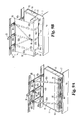
- FIG. 7A is an enlarged perspective view of the bunk of FIG. 2 illustrating another alternate embodiment of the bunk restraining structure with the bunk shown in the fully extended and non-restraining position.
- FIG. 7B is a perspective view of the bunk and bunk restraining structure of FIG. 7A with the bunk in the occupant restraining position.
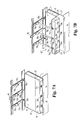
- FIG. 8A is a perspective view of the bunk and bunk restraining structure of FIG. 8B with the bunk shown in the fully extended, non-restraining position and the quick release harness having been released.
- FIG. 8B is an enlarged perspective view of the bunk of FIG. 2 illustrating yet another alternate embodiment of the bunk restraining structure with the bunk in the occupant restraining position.
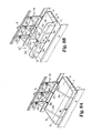
- FIG. 9A is an enlarged perspective view of the bunk of FIG. 2 illustrating a further alternate embodiment of the bunk restraining structure with the bunk shown in the fully extended and non-restraining position.
- FIG. 9B is a perspective view of the bunk and bunk restraining structure of FIG. 9A with the bunk in the occupant restraining position.
- FIG. 10 is an end elevational view of the occupant restraining bunk similar to that of FIG. 2 illustrating an alternate embodiment of a bunk restraining structure.
- FIG. 11 is an end elevational view of an alternate embodiment of an occupant restraining bunk located in the sleeper cab and configured in an occupant restraining position.
-
- For the purposes of promoting an understanding of the principles of the invention, reference will now be made to a number of embodiments illustrated in the drawings and specific language will be used to describe the same. It will nevertheless be understood that no limitation of the scope of the invention is thereby intended.
- Referring now to FIG. 1, there is shown a
truck 10 of the tractor-trailer type. Thetractor portion 11 typically includes asleeper cab 12 located behind the driver for a person or persons to occupy when the truck is in motion or at rest. - Sleeper cabs have a variety of couches or bunks provided therein. Shown in FIG. 2, for example, is a
bunk 13 mounted withincab 12.Bunk 13 includes a main orstationary portion 14 having an upwardly facingsurface 15 upon which aperson 16 may rest.Stationary portion 14 typically is a mattress and is fixed by conventional means toframe 17 which is, in turn, secured to the truck frame. It will be appreciated that although thebunk 13 is illustrated herein as being mounted within thesleeper cab 12 of atruck 10, thebunk 13 may alternatively be provided in, or carried by, a variety of motor vehicles. -
Bunk 13 further includes amovable portion 18 that serves as a barrier or berm restricting movement of an occupant of thebunk 13 in the direction ofmovable portion 18. In the illustrated embodiment,movable portion 18 is pivotally mounted by conventional means, such as ahinge 19 extending between and connectingmovable portion 18 with the stationarymain portion 14. For example,end wall 20 ofstationary portion 14 along withend wall 21 ofmovable portion 18 may be produced from an inflexible material thereby allowing for the mounting ofhinge 19 towalls walls movable portion 18 relative to thestationary portion 14. Furthermore, the connection providing the movement of themovable portion 18 may take various forms which will permit themovable portion 18 to be raised to provide a barrier adjacent to thestationary portion 14. - When the
movable portion 18 is in the downward position shown in FIG. 3, the upwardly facingsurface 24 ofmovable portion 18 is illustratively parallel and aligned with the upwardly facingsurface 15 of thestationary portion 14. Thus, the usable width or occupant-supporting surface of the bunk is composed ofsurfaces width 22 extending from the rear 25 of the bunk to thefront 26 of the bunk. Thus, the bunk is provided with a maximum width of upwardly supporting surface and may be used not only as a bunk but as a chair or couch. - When
movable portion 18 is moved to the upward position shown in FIG. 2,surface 24 extends generally upwardly away fromsurface 15, and in one embodiment is arranged substantially perpendicular tosurface 15. Theusable width 23 of the bunk extending from the rear 25 of the bunk tosurface 24 is less thanwidth 22 withmovable portion 18 providing a barrier to movement of the occupant onsurface 15 in the direction of the longitudinal axis 26 (FIG. 1) of the vehicle.Surfaces axis 26 when themovable portion 18 is in the downward position. The normal direction of travel of the vehicle is shown byarrow 27 alongaxis 26. - Referring now to FIG. 4, one illustrative embodiment of a
restraint 30 is shown extendable upwardly from themovable portion 18 over the stationary ormain portion 14.Restraint 30 may take a variety of configurations, and in the illustrated embodiment shown in FIG. 4, three webs orstraps solid fabric curtain 34. In an alternate embodiment, as illustrated in FIG. 6, the three straps of an alternate restraint 30' are coupled to acurtain 60 formed from a net-like material. It will be appreciated that eithercurtain 34 orcurtain 60 may alternatively be formed of other suitable flexible, or at least partially flexible, material or materials including, but not limited to, any solid or net-like composition of leather, vinyl, fabric, and/or any combination thereof. - The
distal end 35 of therestraint 30 is releasably connectable to the vehicle, e.g., therear wall 36 of the cab, via any number of known fastening mechanisms. In FIG. 4, for example, thedistal end 35 ofrestraint 30 is illustrated as including arod 37 extending across therestraint 30, wherein portions of thedistal end 35 androd 37 combinations are configured to engage three spaced apart hook-shaped brackets orconnectors rear wall 36 of the vehicle. - Brackets 38-40 may be identical and thus the following description relative to
bracket 40 applies equally tobrackets rear cab wall 36. Wall 41 includes a pair of spaced apart and upwardly turnedfingers rod 37. Thus, to releasably connect therestraint 30 to brackets 38-40,rod 37 is moved upwardly atop the fingers of each bracket and then moved downwardly into engagement with the fingers of each bracket. For example, as shown in FIG. 5,rod 37 may be moved upwardly overfingers bracket 40. - Three
retractors straps restraint 30 oncerod 37 is disengaged from clamps 38-40. The retractors may further be spring biased and yieldable to allow extension of the straps therefrom asrestraint 30 is pulled upwardly frommovable portion 18 and overbunk portion 14, thereby allowing the fastening ofrod 37 to clamps 38-40. The retractors may be conventional retracting devices, including, for example, automatic locking retractors or inertia locking retractors. Alternatively or additionally, as shown in phantom in FIGS. 4 and 6,webs retractors bunk 13 and into engagement withcorresponding brackets rear wall 36 of the vehicle, to thereby facilitate securingbunk 13 in the position illustrated in FIGS. 4 and 6. Alternatively still,retractors frame 17 adjacent to themovable portion 18 ofbunk 13, wherein such retractors may or may not be further connected to therear wall 36 or other vehicle structure viawebs - In the embodiment illustrated in FIGS. 4 and 6, retractors 45-47 are fixedly mounted to wall 50 of the
movable portion 18 ofbunk 13, in turn, releasably connected by aquick release mechanism 54 mounted to wall 51.Wall 51 is fixedly mounted to themovable portion 18 and extends generally vertically when themovable portion 18 is in the upward position corresponding to FIGS. 2 and 4. In the embodiment depicted in FIG. 4,wall 51 includes channels or holes 67 that removably receiverods 68 fixedly mounted to and extending fromboard 50. The quick release mechanism may include a buckle/tongue combination 54 with, for example, the buckle mounted to wall 51 and the tongue mounted to wall 50. Thus, a quick release capability is provided wherebybuckle 54 may be unlocked andwall 50 may be pulled upwardly along with retractors 45-47 andrestraint 30. A variety ofquick release mechanisms 54 may be utilized along with a variety ofrestraints 30. - In the embodiment of FIG. 6, the solid
flexible curtain 34 is replaced with a net-like curtain 60 coupled to straps 31a-33a that are received by retractors 45-47 mounted to themovable portion 18. Instead ofrod 37 mounted to the distal ends of straps 31-33, three conventional buckles 61-63 are mounted thereto and are releasably lockable with conventional tongues mounted to backwall 36. Alternatively, conventional tongues are mounted to the distal ends of straps 31-33 and three conventional buckles 61-63 are mounted to backwall 36. - Referring now to FIGS. 7A and 7B, another illustrative embodiment of a
restraint 30" is illustrated. In this embodiment, a number ofconventional retractors rear wall 36, and a corresponding number of webs orstraps tongues conventional buckles brackets underside wall 50 of themovable portion 18 of thebunk 13 via known means as illustrated in phantom byattachment locations brackets straps webs tongues corresponding buckles movable portion 18 ofbunk 13 is cradled bystraps brackets straps webs tongues corresponding buckles movable portion 18 ofbunk 13 is cradled bystraps straps movable portion 18 ofbunk 13 at 75a, 75b and 75c respectively, and mountingbrackets webs tongues corresponding buckles movable portion 18 ofbunk 13 is secured in the position illustrated in FIG. 7B. - Referring now to FIGS. 8A and 8B, another illustrative embodiment of a
restraint 30"' is illustrated.Restraint 30"' may or may not include a quick release mechanism as will be described subsequently. In one embodiment ofrestraint 30"', as illustrated in its restraining position in FIG. 8B, includes a number ofconventional brackets rear wall 36. In this embodiment,brackets brackets rod 88. It will be appreciated, however, thatbrackets brackets rod 88 similarly as described hereinabove. In any case,bracket 80b is attached to one end of a fixed-length or adjustable web orstrap 82b having an opposite end affixed to a buckle-engagingtongue 84. A correspondingbuckle 86 may be mounted to frame 17 via mountingbracket 95, or may alternatively be mounted directly to wall 50 of themovable portion 18 ofbunk 13 at 93b, via web orstrap 92. In one embodiment ofrestraint 30"', first andsecond retractors bracket 95, whereinretractors straps retractors corresponding brackets tongue 84. In this embodiment,webs movable portion 18 ofbunk 13 is secured in the occupant restraining position illustrated in FIG. 8B by first engagingrod 88 withbrackets tongue 84 into engagement withbuckle 86. Alternatively,tongue 84 may be engaged withbuckle 86 before engagingrod 88 withbrackets restraint 30"',structures straps straps 92a and 92c are attached via conventional means to wall 50 of themovable portion 18 ofbunk 13 at 93a and 93c respectively, and mountingbrackets restraint 30"' just described, web orstrap 92 may be attached to frame 17 via mountingbracket 95, or alternatively attached directly to wall 50 of themovable portion 18 ofbunk 13 at 93b, in whichcase mounting bracket 95 may be omitted, or alternatively still structure 95 may represent a conventional retractor in whichcase strap 92 may be fixed or variable length. In any case,restraint 30"' is in its occupant restraining position whenrod 88 is engaged withbrackets tongue 84 is engaged withbuckle 86, as illustrated in FIG. 8B. In this embodiment, buckle 86 acts as a quick release mechanism such thatbuckle 86 may be actuated to releasetongue 84 therefrom, which causestongue 84 to move towardbracket 80b thereby introducing slack into webs orstraps movable portion 18 ofbunk 13 to its non-restraining position as illustrated in FIG. 8A. - Referring now to FIGS. 9A and 9B, yet another illustrative embodiment of a
restraint 30"" is illustrated. This embodiment is identical in many respects to therestraint 30"' illustrated and described with respect to FIGS. 8A and 8B, and like numbers are therefore used to identify like components. Structural and functional descriptions of such identical components will, however, be omitted here for brevity. In this embodiment, acurtain 92 is attached at oneend 92a to themovable portion 18 ofbunk 13.Curtain 92 may be a solid, mesh or net-like flexible material as described hereinabove with respect to FIGS. 4 and 6. In any case, webs orstraps curtain 92 prior to being looped throughbrackets straps brackets strap 82b, travel alongcurtain 92 on the bunk side thereof for releasable engagement withbuckle 86. As most clearly illustrated in FIG. 9A,curtain 92 is configured to fold (e.g., in corrugated fashion) adjacent to themovable portion 18 ofbunk 13 when thetongue 84 is released from thebuckle 86 such that themovable portion 18 moves to its downward, occupant non-restraining position. Optionally, as shown in phantom in FIG. 9A, acurtain housing 94 may be positioned adjacent to themovable portion 18 and mounted to frame 17 such thatcurtain 92 is received within, or adjacent to,housing 94 in its folded or retracted position. - In alternate embodiments of the
restraint 30"' or 30"" illustrated in either of FIGS. 8A and 8B or 9A and 9B,rod 88 may be omitted,brackets straps bracket 80b may be a conventional bracket configured to secure web orstrap 82b (either fixed length or adjustable) towall 36. In this embodiment, the occupant non-restraining position ofbunk 13 andrestraint 30"' or 30"" is as illustrated in FIGS. 8A and 9A with themovable portion 18 ofbunk 13 in its downward non-restraining position and with webs orstraps bunk 13 as shown.Restraint 30"' or 30"", along withbunk 13, may be moved to their occupant restraining positions, in this embodiment, simply by engagingtongue 84 withbuckle 86, as substantially illustrated in FIGS. 8A and 8B. - Referring now to FIG. 10, an alternate embodiment of a bunk restraining structure is illustrated. This embodiment is identical in many respects to the bunk restraining structure illustrated in FIG. 2, and like numbers are therefore used to identify like components. For example,
bunk 13 is shown supported byframe 17 of a vehicle, with the movable portion ofbunk 13 in its occupant restraining position as illustrated in FIG. 2. In this embodiment, a web orstrap 102 is connected at one end to a retractor, bracket orother attachment structure 106 affixed or mounted to themovable portion 18 ofbunk 13, or is alternatively connected at this end to a retractor, bracket ofother attachment structure 108 affixed to frame 17, as described in any one or more of the embodiments illustrated and described herein. Unlike the various embodiments illustrated and described thus far, the opposite end of web orstrap 102 is not attached to therear wall 36 of the vehicle but is instead attached to a retractor, bracket or other suitable attachment mechanism affixed to a ceiling orroof 100 of the vehicle. As in previously described embodiments, the web orstrap 102 andattachment structures movable portion 18 ofbunk 13 in the occupant restraining position illustrated in FIG. 10. - Referring now to FIG. 11, an alternate embodiment of a bunk 13' is illustrated. In this embodiment, bunk 13' is a unitary but flexible structure having a stationary portion 14' defining a
top surface 116 and a bunk end 25' abuttingwall 36, and amovable portion 110 defining atop surface 116 terminating at an opposite bunk end 26'. The bunk 13' is bendable atbend location 112 such that surface 114 extends generally upwardly and away fromsurface 116 to form an occupant restraining barrier between end 26' andbend location 112. Any one or combination of the bunk restraining structures described hereinabove may be used to maintain themovable portion 110 of bunk 13' in the illustrated occupant-restraining position, including any of those that attach to therear wall 36, the ceiling orroof 100 or any other vehicle structure. In this embodiment, bunk 13' may be a conventional flexible mattress, or may instead be a flexible bunk configured to facilitate bending along bendinglocation 112. - While the invention has been illustrated and described in detail in the foregoing drawings and description, the same is to be considered as illustrative and not restrictive in character, it being understood that only illustrative embodiments thereof have been shown and described and that all changes and modifications that come within the spirit of the invention are desired to be protected.
Claims (16)
- A sleeper bunk restraining system, comprising a sleeper bunk configured to be carried by a vehicle and having a top surface defining a length upon which an occupant may rest, said bunk including a stationary portion and a movable portion defined along said length, said movable portion movable relative to said stationary portion to form an occupant restraining barrier; and
means for restraining movement of said movable portion of said bunk relative to said stationary portion of said bunk to thereby maintain said occupant restraining barrier in an occupant restraining position. - The sleeper bunk restraining system of claim 1 wherein said movable portion of said bunk defines a first surface and said stationary portion of said bunk defines a second surface, said movable portion of said bunk movable relative to said stationary portion of said bunk such that said first surface extends generally upwardly and away from said second surface.
- A sleeper bunk restraining system, comprising:a sleeper bunk configured to be carried by a vehicle and having a top surface defining a length upon which an occupant may rest, said bunk including a stationary portion and a movable portion defined along said length, said movable portion movable relative to said stationary portion to form an occupant restraining barrier; anda restraining member configured for releasable connection to the vehicle, said restraining member restraining movement of said movable portion of said bunk relative to said stationary portion of said bunk to thereby maintain said occupant restraining barrier in an occupant restraining position when releasably connected.
- The sleeper bunk restraining system of claim 3 wherein said restraining member includes at least one elongated web having a first end connected to said movable portion of said bunk and a second end configured for releasable connection to the vehicle.
- The sleeper bunk restraining system of claim 3 wherein said restraining member includes:a number of elongated webs each having first ends connected in spaced apart relationship to said movable portion of said bunk; anda curtain connected to each of said number of elongated webs, said curtain defining a connecting end configured for releasable connection to the vehicle.
- The sleeper bunk restraining system of claim 3 wherein said restraining member includes at least one elongated web having a first end configured for connection to the vehicle adjacent to said movable portion of said bunk and a second end configured for releasable connection to the vehicle, said at least one elongated web cradling said movable portion of said bunk therein when said restraining member is releasably connected.
- The sleeper bunk restraining system of claim 3 wherein said restraining system includes:a plurality of retractors mounted to said movable portion of said bunk in spaced apart relationship, each of said plurality of retractors including an elongated web having one end connected to a corresponding retractor and an opposite end defining a tongue; anda corresponding plurality of buckles configured for connection to the vehicle, each of said plurality of buckles configured to releasably engage a tongue of a corresponding one of said plurality of retractors.
- The sleeper bunk restraining system of claim 3 wherein said restraining system includes:a plurality of retractors configured for mounting to the vehicle adjacent to said movable portion of said bunk in spaced apart relationship, each of said plurality of retractors including an elongated web having one end connected to a corresponding retractor and an opposite end defining a tongue; anda corresponding plurality of buckles configured for connection to the vehicle, each of said plurality of buckles configured to releasably engage a tongue of a corresponding one of said plurality of retractors such that one or more of said elongated webs cradle said movable portion of said bunk therein when said buckles engage said tongues.
- The sleeper bunk restraining system of claim 3 wherein said restraining system includes:a plurality of retractors configured for mounting to the vehicle in spaced apart relationship, each of said plurality of retractors including an elongated web having one end connected to a corresponding retractor and an opposite end defining a tongue; anda corresponding plurality of buckles mounted to said movable portion of said bunk in spaced apart relationship, each of said plurality of buckles configured to releasably engage a tongue of a corresponding one of said plurality of retractors.
- The sleeper bunk restraining system of claim 3 wherein said restraining system includes:a plurality of retractors configured for mounting to the vehicle in spaced apart relationship, each of said plurality of retractors including an elongated web having one end connected to a corresponding retractor and an opposite end defining a tongue; anda corresponding plurality of buckles configured for connection to the vehicle adjacent to said movable portion of said bunk, each of said plurality of buckles configured to releasably engage a tongue of a corresponding one of said plurality of retractors such that one or more of said elongated webs cradle said movable portion of said bunk therein when said buckles engage said tongues.
- The sleeper bunk restraining system of claim 3 wherein said restraining system includes:a plurality of retractors configured for mounting to the vehicle adjacent to said movable portion of said bunk, each of said plurality of retractors including a retractable web having one end connected to a corresponding retractor and an opposite end;a buckle attached to an opposite end of a first one of said retractable websa fixed-length web having one end attached to a first bracket configured for mounting to the vehicle and an opposite end attached to a tongue;a second bracket configured for mounting to the vehicle in spaced apart relationship to said first bracket, said second bracket slidingly receiving therethrough a second one of said retractable webs connected at its opposite end to said tongue; anda third bracket configured for mounting to the vehicle in spaced apart relationship to said first and second brackets, said third bracket slidingly receiving therethrough a third one of said retractable webs connected at its opposite end to said tongue, said buckle configured to releasably engage said tongue such that at least said first, second and third retractable webs cradle said movable portion of said bunk therein when said buckle engages said tongue.
- In combination:a motor vehicle defining a direction of travel; anda sleeper bunk carried by said vehicle and having a length extending generally transverse relative to said direction of travel, said bunk having a stationary portion defining an occupant supporting surface and a movable portion defined along said length, said movable portion movable relative to said stationary portion to form an occupant restraining barrier along said length for restraining occupant movement along said direction of travel.
- The combination of claim 12 further including a restraint member mounted at one end to said movable portion of said bunk and releasably connectable at an opposite end to said vehicle, said restraint member restraining movement of said movable portion of said bunk relative to said stationary portion of said bunk when connected at said opposite end to said vehicle.
- The combination of claim 12 further including a restraint member mounted at one end to said vehicle adjacent to said movable portion of said bunk and releasably connectable at an opposite end to said vehicle, said restraint member cradling said movable portion of said bunk therein to thereby restrain movement of said movable portion of said bunk relative to said stationary portion of said bunk when connected at said opposite end to said vehicle.
- The combination of claim 12 further including a restraint member mounted at one end to said vehicle and releasably connectable at an opposite end to said movable portion of said bunk, said restraint member restraining movement of said movable portion of said bunk relative to said stationary portion of said bunk when connected at said opposite end to said movable portion of said bunk.
- The combination of claim 12 further including a restraint member mounted at one end to said vehicle and releasably connectable at an opposite end to said vehicle adjacent to said movable portion of said bunk, said restraint member cradling said movable portion of said bunk therein to thereby restrain movement of said movable portion of said bunk relative to said stationary portion of said bunk when connected at said opposite end to said vehicle.
Applications Claiming Priority (2)
| Application Number | Priority Date | Filing Date | Title |
|---|---|---|---|
| US10/200,394 US7097204B2 (en) | 2002-07-22 | 2002-07-22 | Sleeper bunk restraint system |
| US200394 | 2002-07-22 |
Publications (2)
| Publication Number | Publication Date |
|---|---|
| EP1384621A2 true EP1384621A2 (en) | 2004-01-28 |
| EP1384621A3 EP1384621A3 (en) | 2005-03-23 |
Family
ID=30000070
Family Applications (1)
| Application Number | Title | Priority Date | Filing Date |
|---|---|---|---|
| EP03254207A Withdrawn EP1384621A3 (en) | 2002-07-22 | 2003-07-02 | Sleeper bunk restraint system |
Country Status (3)
| Country | Link |
|---|---|
| US (1) | US7097204B2 (en) |
| EP (1) | EP1384621A3 (en) |
| AU (1) | AU2003208128B2 (en) |
Cited By (3)
| Publication number | Priority date | Publication date | Assignee | Title |
|---|---|---|---|---|
| WO2007069947A1 (en) * | 2005-12-13 | 2007-06-21 | Volvo Lastvagnar Ab | Bunk arrangement with partition device |
| CN102658786A (en) * | 2012-05-03 | 2012-09-12 | 姜冰 | Automobile safety cabin |
| EP4306360A1 (en) * | 2022-07-12 | 2024-01-17 | Volvo Truck Corporation | Lower bunk system for an industrial vehicle |
Families Citing this family (41)
| Publication number | Priority date | Publication date | Assignee | Title |
|---|---|---|---|---|
| US7077430B2 (en) * | 2002-08-21 | 2006-07-18 | Volvo Lastvagnar Ab | Vehicle comprising a seat fitted in the transverse direction of the vehicle |
| US20060103154A1 (en) * | 2003-12-10 | 2006-05-18 | Berry C G | Emergency mobile sleep units |
| US20060002403A1 (en) * | 2004-06-30 | 2006-01-05 | Glenayre Electronics, Inc. | Distributed IP architecture for telecommunications system |
| CN100368232C (en) * | 2004-09-07 | 2008-02-13 | 廖光华 | Protector of vehicle for passenger |
| WO2006055005A1 (en) * | 2004-11-19 | 2006-05-26 | Volvo Trucks North America | Dual berth invertible bunk |
| SE0500509L (en) * | 2005-03-04 | 2006-06-13 | Volvo Lastvagnar Ab | safety net |
| DE102005014997B4 (en) * | 2005-04-01 | 2007-04-12 | Airbus Deutschland Gmbh | Restraint system and blanket with integrated retention function |
| US7631896B2 (en) * | 2005-04-15 | 2009-12-15 | Indiana Mills & Manufacturing, Inc. | Sleeper bunk restraint system for a vehicle |
| DE102006032558A1 (en) * | 2006-07-12 | 2008-01-17 | Autoliv Development Ab | Safety device for heavy goods vehicle driver cabin, has restraint net stretched out in event of vehicle overturning |
| US7552488B2 (en) * | 2006-08-16 | 2009-06-30 | International Truck Intellectual Property Company, Llc | Restraint device for a bed in a motor vehicle |
| US20090058138A1 (en) * | 2007-05-23 | 2009-03-05 | Cech Paul G | Sleeper bed for use in vehicle |
| US20090025616A1 (en) * | 2007-07-23 | 2009-01-29 | Amsafe, Inc. | Air cargo pallets having synthetic cores and associated systems and methods for manufacturing same |
| US7837275B2 (en) * | 2007-09-06 | 2010-11-23 | Evenflo Company, Inc. | Attachment mechanism with interlocked belt retractor |
| US8123279B2 (en) * | 2008-03-31 | 2012-02-28 | Honda Motor Company, Ltd. | Net structures, vehicles including net structures, and methods |
| US7883133B2 (en) * | 2008-04-15 | 2011-02-08 | Ferno-Washington, Inc. | Apparatus and methods for litter support system for vehicles |
| US8992238B2 (en) | 2010-07-12 | 2015-03-31 | Ferno-Washington, Inc. | Mounting system having a mounting plate with mounting studs and electrical contacts |
| US8636154B2 (en) | 2010-07-12 | 2014-01-28 | Ferno-Washington, Inc. | Litter support systems for medical care units and methods of their use |
| US8308223B2 (en) | 2010-08-03 | 2012-11-13 | Honda Motor Company, Ltd. | Net structure for a vehicle |
| US8414046B2 (en) * | 2010-11-19 | 2013-04-09 | Nissan North America, Inc. | Reinforced vehicle structure |
| AU2013203990B2 (en) | 2012-02-14 | 2015-01-22 | Ferno-Washington, Inc. | Quick antenna attachment and methods of their use |
| KR101326041B1 (en) * | 2012-08-20 | 2013-11-07 | (주)에이스 힌지텍 | (a panel for hanging and device for hanging using the same |
| WO2014031109A1 (en) * | 2012-08-22 | 2014-02-27 | Volvo Group North America, Llc | Roll over bunk restraint system and method |
| US9944217B2 (en) | 2013-02-11 | 2018-04-17 | Ferno-Washington, Inc. | Equipment mounting system |
| EP3354246B1 (en) | 2013-02-11 | 2019-10-23 | Ferno-Washington, Inc. | Equipment mounting system |
| US10307313B2 (en) | 2013-02-11 | 2019-06-04 | Ferno-Washington, Inc. | Equipment mounting system |
| NL2011318C2 (en) * | 2013-08-20 | 2015-02-23 | Driessen Aircraft Interior Systems Europ B V | Crew rest area on board of a vehicle, in particular an airplane. |
| US10398203B2 (en) | 2014-02-11 | 2019-09-03 | Ferno-Washington, Inc. | Crash-ready, portable, compartmentalization device |
| US10398207B2 (en) | 2014-02-11 | 2019-09-03 | Ferno-Washington, Inc. | Crash-ready, portable, compartmentalization device |
| US11083265B2 (en) | 2014-02-11 | 2021-08-10 | Ferno-Washington, Inc. | Magnetic pouch attachment mechanism with crash stable locking teeth |
| ES2702295T3 (en) | 2014-07-18 | 2019-02-28 | Ferno Washington | A compartmentalization device, portable prepared for collisions |
| USD844347S1 (en) * | 2017-08-07 | 2019-04-02 | Gerald Bosstick | Inflatable aircraft mattress |
| USD964072S1 (en) | 2019-10-09 | 2022-09-20 | Jetbed, Inc. | Inflatable aircraft bed |
| USD964073S1 (en) | 2019-12-10 | 2022-09-20 | Jetbed, Inc. | Inflatable aircraft bed and carrying case assembly |
| CA3109583C (en) | 2020-02-20 | 2025-09-02 | Jetbed, Inc. | Inflatable bed with air ducts |
| US12310901B2 (en) * | 2020-02-28 | 2025-05-27 | Technologies Cgc Inc. | Coupling systems for releasably coupling equipment to a patient transport systems |
| US11603028B2 (en) * | 2020-05-07 | 2023-03-14 | Ford Global Technologies, Llc | Accessories for vehicles with removable doors |
| USD948247S1 (en) | 2020-10-20 | 2022-04-12 | Jetbed, Inc. | Inflatable aircraft bed |
| USD1015021S1 (en) | 2021-12-08 | 2024-02-20 | Jetbed, Inc. | Inflatable aircraft bed with carrying case and vacuum bag |
| USD1002239S1 (en) | 2022-01-19 | 2023-10-24 | Jetbed, Inc. | Inflatable aircraft bed with vacuum bag |
| US12356960B2 (en) * | 2022-08-04 | 2025-07-15 | Ultimate Pet Bed Llc | Portable pet bed assembly |
| US20250229608A1 (en) * | 2024-01-17 | 2025-07-17 | Darrin Molloy | Protective device for dogs or other animals riding in vehicles with heads protruding therefrom |
Citations (11)
| Publication number | Priority date | Publication date | Assignee | Title |
|---|---|---|---|---|
| US1336943A (en) | 1917-06-04 | 1920-04-13 | Jr Richard T Crane | Safety-spring for berths, &c. |
| US3695698A (en) | 1971-06-01 | 1972-10-03 | Mark Trucks Inc | Restraint device for vehicle cab sleeper bunk |
| US4943105A (en) | 1989-03-27 | 1990-07-24 | Kacar David J | Automobile pet seat and cargo carrier |
| EP0415041A1 (en) | 1989-08-29 | 1991-03-06 | MAN Nutzfahrzeuge Aktiengesellschaft | Sleeping berth in the driver's cab of a commercial vehicle |
| US5375879A (en) | 1993-08-10 | 1994-12-27 | Indiana Mills & Manufacturing, Inc. | Vehicle sleeper restraint |
| US5529341A (en) | 1994-11-21 | 1996-06-25 | Hartigan; Gail J. | Restraining net for passenger vehicles |
| US5536042A (en) | 1995-04-17 | 1996-07-16 | Indiana Mills And Manufacturing, Inc. | Vehicle bunk and occupant restraint system |
| US6217069B1 (en) | 1999-04-12 | 2001-04-17 | Palvannanathan Ganesan | Safety restraint for a horizontal passenger |
| WO2002016172A1 (en) | 2000-08-22 | 2002-02-28 | Volvo Lastvagnar Ab | Safety arrangement for a bed in a vehicle |
| US6367839B1 (en) | 1999-03-05 | 2002-04-09 | Volvo Trucks North America, Inc. | Padded bunk restraint |
| US6405391B1 (en) | 1999-07-15 | 2002-06-18 | Klippan Safety Ab | Bunk arrangement in a truck cab |
Family Cites Families (14)
| Publication number | Priority date | Publication date | Assignee | Title |
|---|---|---|---|---|
| US3648306A (en) * | 1970-06-11 | 1972-03-14 | Seymour Auerbach | Protective and support device for vehicle travel |
| US3887229A (en) * | 1974-02-11 | 1975-06-03 | Travel Products Inc | Convertible seat |
| US4292698A (en) * | 1979-08-22 | 1981-10-06 | J. F. Enterprises, Inc. | Convertible sofa-bed with back restraining mechanism |
| US4368902A (en) * | 1980-11-24 | 1983-01-18 | Paccar Inc. | Combination curtain and restraint system for a vehicle bunk |
| US4487451A (en) * | 1982-02-24 | 1984-12-11 | Fiorini Paul J | Sleeper seat |
| US4509788A (en) * | 1982-12-14 | 1985-04-09 | Jan Ping Shuenn | Safety arrangement in a taxi |
| US4512286A (en) * | 1983-06-20 | 1985-04-23 | Rux Paul R | Pet seat for automobiles |
| DE4438910C1 (en) * | 1994-11-03 | 1996-03-21 | Butz Peter Verwaltung | Restraint device for the hold of motor vehicles, such as. B. for combination cars or large passenger cars |
| DE19544014A1 (en) * | 1995-11-27 | 1997-05-28 | Aguti Prod Entw & Design Gmbh | Folding bench |
| DE19728550B4 (en) * | 1996-07-16 | 2009-02-05 | Volkswagen Ag | Cargo securing device for a cargo space of a motor vehicle |
| US5690355A (en) * | 1996-12-10 | 1997-11-25 | Alliedsignal Inc. | Vehicle sleeper bunk restraint system |
| US6217068B1 (en) * | 1998-09-16 | 2001-04-17 | Pat C. Trainum | Safety belt for a sleeping child/small person in a vehicle |
| US6439636B1 (en) * | 2001-02-07 | 2002-08-27 | Ming C. Kuo | Vehicle electric reclining seats |
| US6428044B1 (en) | 2001-08-23 | 2002-08-06 | Volvo Trucks North America, Inc. | Bunk restraint |
-
2002
- 2002-07-22 US US10/200,394 patent/US7097204B2/en not_active Expired - Lifetime
-
2003
- 2003-07-02 EP EP03254207A patent/EP1384621A3/en not_active Withdrawn
- 2003-07-03 AU AU2003208128A patent/AU2003208128B2/en not_active Ceased
Patent Citations (11)
| Publication number | Priority date | Publication date | Assignee | Title |
|---|---|---|---|---|
| US1336943A (en) | 1917-06-04 | 1920-04-13 | Jr Richard T Crane | Safety-spring for berths, &c. |
| US3695698A (en) | 1971-06-01 | 1972-10-03 | Mark Trucks Inc | Restraint device for vehicle cab sleeper bunk |
| US4943105A (en) | 1989-03-27 | 1990-07-24 | Kacar David J | Automobile pet seat and cargo carrier |
| EP0415041A1 (en) | 1989-08-29 | 1991-03-06 | MAN Nutzfahrzeuge Aktiengesellschaft | Sleeping berth in the driver's cab of a commercial vehicle |
| US5375879A (en) | 1993-08-10 | 1994-12-27 | Indiana Mills & Manufacturing, Inc. | Vehicle sleeper restraint |
| US5529341A (en) | 1994-11-21 | 1996-06-25 | Hartigan; Gail J. | Restraining net for passenger vehicles |
| US5536042A (en) | 1995-04-17 | 1996-07-16 | Indiana Mills And Manufacturing, Inc. | Vehicle bunk and occupant restraint system |
| US6367839B1 (en) | 1999-03-05 | 2002-04-09 | Volvo Trucks North America, Inc. | Padded bunk restraint |
| US6217069B1 (en) | 1999-04-12 | 2001-04-17 | Palvannanathan Ganesan | Safety restraint for a horizontal passenger |
| US6405391B1 (en) | 1999-07-15 | 2002-06-18 | Klippan Safety Ab | Bunk arrangement in a truck cab |
| WO2002016172A1 (en) | 2000-08-22 | 2002-02-28 | Volvo Lastvagnar Ab | Safety arrangement for a bed in a vehicle |
Cited By (4)
| Publication number | Priority date | Publication date | Assignee | Title |
|---|---|---|---|---|
| WO2007069947A1 (en) * | 2005-12-13 | 2007-06-21 | Volvo Lastvagnar Ab | Bunk arrangement with partition device |
| US7823962B2 (en) | 2005-12-13 | 2010-11-02 | Volvo Lastvagnar Ab | Bunk arrangement with partition device |
| CN102658786A (en) * | 2012-05-03 | 2012-09-12 | 姜冰 | Automobile safety cabin |
| EP4306360A1 (en) * | 2022-07-12 | 2024-01-17 | Volvo Truck Corporation | Lower bunk system for an industrial vehicle |
Also Published As
| Publication number | Publication date |
|---|---|
| AU2003208128B2 (en) | 2009-01-29 |
| EP1384621A3 (en) | 2005-03-23 |
| US20040012183A1 (en) | 2004-01-22 |
| US7097204B2 (en) | 2006-08-29 |
| AU2003208128A1 (en) | 2004-02-12 |
Similar Documents
| Publication | Publication Date | Title |
|---|---|---|
| EP1384621A2 (en) | Sleeper bunk restraint system | |
| US6367839B1 (en) | Padded bunk restraint | |
| US5536042A (en) | Vehicle bunk and occupant restraint system | |
| US9840169B2 (en) | Child safety seat | |
| US7770969B2 (en) | Vehicle safety restraint system | |
| US6962382B2 (en) | Barrier system | |
| EP2330947B1 (en) | Baby changing system for automobiles | |
| US8573664B2 (en) | Pet barrier and cover | |
| US5647611A (en) | Vehicle safety belt system | |
| US4889389A (en) | Seat with three point user restraint | |
| US11964602B2 (en) | Support system providing a supporting surface for rest in a vehicle | |
| EP0888936A2 (en) | Vehicle occupant restraint having an adjustable web tether | |
| US9010863B2 (en) | Bus seating system | |
| CN213473061U (en) | Seat belt assembly | |
| EP1557327A1 (en) | Buckle assembly | |
| CA2352757C (en) | Automotive seat belt restraint assembly | |
| US7150471B2 (en) | Cushioned restraint system | |
| CN102883924B (en) | Belt system in transport facility | |
| US20150191148A1 (en) | Sleeper Berth Restraint | |
| JP2000255355A (en) | Simple separator | |
| EP1147946B1 (en) | A safety net arrangement for a bunk in a truck cab | |
| GB2402370A (en) | Buckle head and strap arrangement | |
| CN223515497U (en) | Pet cage | |
| JPS5833549A (en) | Seat fixing type seat belt device | |
| JPS5833004Y2 (en) | Seat belt attachment device for buses, etc. |
Legal Events
| Date | Code | Title | Description |
|---|---|---|---|
| PUAI | Public reference made under article 153(3) epc to a published international application that has entered the european phase |
Free format text: ORIGINAL CODE: 0009012 |
|
| AK | Designated contracting states |
Kind code of ref document: A2 Designated state(s): AT BE BG CH CY CZ DE DK EE ES FI FR GB GR HU IE IT LI LU MC NL PT RO SE SI SK TR |
|
| AX | Request for extension of the european patent |
Extension state: AL LT LV MK |
|
| RIN1 | Information on inventor provided before grant (corrected) |
Inventor name: BITTNER, DOUGLAS WAYNE Inventor name: JESSUP, CHRIS P. |
|
| PUAL | Search report despatched |
Free format text: ORIGINAL CODE: 0009013 |
|
| AK | Designated contracting states |
Kind code of ref document: A3 Designated state(s): AT BE BG CH CY CZ DE DK EE ES FI FR GB GR HU IE IT LI LU MC NL PT RO SE SI SK TR |
|
| AX | Request for extension of the european patent |
Extension state: AL LT LV MK |
|
| RBV | Designated contracting states (corrected) |
Designated state(s): AT BE BG CH CY CZ DE DK EE ES FI FR GB GR HU IE IT LI LU MC NL PT RO SE SI SK TR |
|
| 17P | Request for examination filed |
Effective date: 20050711 |
|
| AKX | Designation fees paid |
Designated state(s): DE ES FR GB IT SE |
|
| 17Q | First examination report despatched |
Effective date: 20060329 |
|
| STAA | Information on the status of an ep patent application or granted ep patent |
Free format text: STATUS: THE APPLICATION IS DEEMED TO BE WITHDRAWN |
|
| 18D | Application deemed to be withdrawn |
Effective date: 20111222 |