EP1384319B1 - Variable empfindlichkeitssteuerung für ein innenohrimplantat - Google Patents
Variable empfindlichkeitssteuerung für ein innenohrimplantat Download PDFInfo
- Publication number
- EP1384319B1 EP1384319B1 EP02713943.5A EP02713943A EP1384319B1 EP 1384319 B1 EP1384319 B1 EP 1384319B1 EP 02713943 A EP02713943 A EP 02713943A EP 1384319 B1 EP1384319 B1 EP 1384319B1
- Authority
- EP
- European Patent Office
- Prior art keywords
- amplifier
- gain
- noise floor
- emin
- current estimated
- Prior art date
- Legal status (The legal status is an assumption and is not a legal conclusion. Google has not performed a legal analysis and makes no representation as to the accuracy of the status listed.)
- Expired - Lifetime
Links
Images



Classifications
-
- H—ELECTRICITY
- H04—ELECTRIC COMMUNICATION TECHNIQUE
- H04R—LOUDSPEAKERS, MICROPHONES, GRAMOPHONE PICK-UPS OR LIKE ACOUSTIC ELECTROMECHANICAL TRANSDUCERS; ELECTRIC HEARING AIDS; PUBLIC ADDRESS SYSTEMS
- H04R25/00—Electric hearing aids
- H04R25/60—Mounting or interconnection of hearing aid parts, e.g. inside tips, housings or to ossicles
- H04R25/604—Mounting or interconnection of hearing aid parts, e.g. inside tips, housings or to ossicles of acoustic or vibrational transducers
- H04R25/606—Mounting or interconnection of hearing aid parts, e.g. inside tips, housings or to ossicles of acoustic or vibrational transducers acting directly on the eardrum, the ossicles or the skull, e.g. mastoid, tooth, maxillary or mandibular bone, or mechanically stimulating the cochlea, e.g. at the oval window
-
- H—ELECTRICITY
- H04—ELECTRIC COMMUNICATION TECHNIQUE
- H04R—LOUDSPEAKERS, MICROPHONES, GRAMOPHONE PICK-UPS OR LIKE ACOUSTIC ELECTROMECHANICAL TRANSDUCERS; ELECTRIC HEARING AIDS; PUBLIC ADDRESS SYSTEMS
- H04R25/00—Electric hearing aids
- H04R25/35—Electric hearing aids using translation techniques
- H04R25/356—Amplitude, e.g. amplitude shift or compression
Definitions
- the present invention relates to a method and device for controlling the sensitivity and gain of an amplifier used in a hearing device, such as a hearing aid or cochlear implant.
- cochlear implant systems have been developed. Such systems bypass the hair cells in the cochlea and directly deliver electrical stimulation to the auditory nerve fibres, thereby allowing the brain to perceive a hearing sensation resembling the natural hearing sensation normally delivered to the auditory nerve.
- US Patent 4532930 provides a description of one type of traditional cochlear implant system.
- EP 0 326 905 teaches a hearing aid signal-processing system that estimates the absolute quantity of noise in each of a plurality of frequency bands. The gain of the individual bands are adjusted so as to minimize the effect of upward masking spread. Gain is adjusted based on whether a particular sound event is substantially louder than an ambient signal level by a given amount above an average signal level. In EP 0 326 905 , if a particular sound event is substantially louder than an ambient signal level by a given amount above an average signal level, the amplitude of the sound event less than a threshold is used as the basis for computation of the gain to be applied.
- cochlear implant systems have consisted of essentially two components, an external component commonly referred to as a processor unit and an internal implanted component commonly referred to as a stimulator/receiver unit. Traditionally, both of these components have cooperated together to provide the sound sensation to a user.
- the external component has traditionally consisted of a microphone for detecting sounds, such as speech and environmental sounds, a speech processor that converts the detected sounds, particularly speech, into a coded signal, a power source such as a battery, and an external transmitter coil.
- the coded signal output by the speech processor is transmitted transcutaneously to the implanted stimulator/receiver unit situated within a recess of the temporal bone of the user.
- This transcutaneous transmission occurs via the external transmitter coil which is positioned to communicate with an implanted receiver coil provided with the stimulator/receiver unit.
- This communication serves two essential purposes, firstly to transcutaneously transmit the coded sound signal and secondly to provide power to the implanted stimulator/receiver unit.
- this link has been in the form of an RF link, but other such links have been proposed and implemented with varying degrees of success.
- the implanted stimulator/receiver unit traditionally includes a receiver coil that receives the coded signal and power from the external processor component, and a stimulator that processes the coded signal and outputs a stimulation signal to an intracochlea electrode assembly which applies the electrical stimulation directly to the auditory nerve producing a hearing sensation corresponding to the original detected sound.
- the external componentry has been carried on the body of the user, such as in a pocket of the user's clothing, a belt pouch or in a harness, while the microphone has been mounted on a clip mounted behind the ear or on the lapel of the user.
- the physical dimensions of the speech processor have been able to be reduced allowing for the external componentry to be housed in a small unit capable of being worn behind the ear of the user.
- This unit allows the microphone, power unit and the speech processor to be housed in a single unit capable of being discretely worn behind the ear, with the external transmitter coil still positioned on the side of the user's head to allow for the transmission of the coded sound signal from the speech processor and power to the implanted stimulator unit.
- the processor used feature extraction strategies to identify the speech features present in the signal from the microphone and encode them as patterns of electrical stimulation.
- the features of the speech that were extracted were the fundamental frequency (or voice pitch) and the amplitudes and frequencies of the first and second formants of the speech spectrum.
- Such processing had the advantage that the hardware required to perform the feature extraction could be relatively simple so leading to a relatively low power consumption.
- Strategies that employed this feature extraction philosophy were found to work particularly well when the user was listening to a single voice in a quiet environment, however, when the user was in an environment with background noise the strategy was not nearly as successful. If, for example, two people were speaking at the same time, then two first formants would be mixed. The processor in expecting only one formant provided a single estimate of this formant which was a mixture of the two. The result was a signal which the user could not readily understand.
- a speech processor firstly typically includes a preamplifier and automatic gain control (AGC).
- the preamplifier amplifies the very low signal detected from the microphone to a suitable level that can be handled by the rest of the speech processor.
- the AGC controls the level of the signal so that it does not overload or distort.
- the AGC can have what is known as infinite compression in that the signal is amplified by a fixed gain until the output signal reaches a certain maximum level, at which the gain is reduced to prevent the output signal from exceeding that level. For example, the gain may be controlled in order to ensure that an output signal never exceeds a maximum comfort value for the user.
- AGC automatic gain control
- ASC Automatic Sensitivity Control
- the ASC controls the background noise level by constantly monitoring the signal from the microphone and recording the minimum level to which it drops over a period of several seconds (generally 5-10 seconds). This minimum level is called the noise floor.
- the ASC adjusts the gain so that the noise floor is held below a predetermined breakpoint, usually so that the user's threshold hearing level corresponds approximately to the noise floor.
- the gain sensitivity adjustment may be made manually or by an automatic means such as is described in International Publication No WO 96/13096 .
- the present inventors have recognised the shortcomings of current hearing device sensitivity control techniques and practices in the prior art and accordingly have sought to provide an improved system and method of controlling the sensitivity of hearing devices, such as cochlear implants.
- the present invention resides in an amplifier for providing adaptive operation of an auditory prosthesis, the amplifier operable to receive an input signal and produce an output signal, the amplifier comprising:
- Embodiments of the invention may thus ensure that all input signals which are substantially equal to or above the current estimated noise floor value will be converted to an output signal above or at the hearing threshold value, and accordingly, will be passed to the auditory nerve of a user of an auditory prosthesis incorporating such an amplifier in a perceptible manner. Further, by altering the gain compression ratio, the present invention allows for adaptive operation of the amplifier responsive to varying noise floor levels, while maintaining desired gain characteristics of the amplifier across a range of input signal levels.
- the present invention resides in a method for controlling the gain of an amplifying means of an auditory prosthesis, the amplifying means operable to receive an input signal and produce an output signal, the method comprising the steps of:
- the current estimated noise floor value is preferably derived from the input signal, and may be substantially continuously updated or only periodically updated. Ongoing derivation and updating of the current estimated noise floor value enables the amplifier to adapt to ongoing changes in the current estimated noise floor value.
- the step of determining a current estimated noise floor value may for example be carried out continuously, periodically or repeatedly, and may be carried out simultaneously with one or more other steps of the method of the present invention.
- the step of determining a current estimated noise floor value may comprise continuously monitoring an envelope of an input signal and determining the current estimated noise floor value based on detected minima of that envelope.
- the amplifier gain may vary for differing input signal levels. That is, the amplifier response may be non-linear for changing input signal levels.
- the dynamic range of the amplifier is increased in response to a decrease in the current estimated noise floor value.
- the dynamic range of the amplifier is preferably decreased in response to an increase in the current estimated noise floor value.
- the amplifier response is continuous, monotonic and increasing for all output signal levels between the hearing threshold value and the maximum comfort value.
- the amplifier preferably produces an output signal equal in magnitude to the hearing threshold value when the input signal equals the current estimated noise floor level.
- the gain control means ensures that the amplifier does not produce any output signals which exceed a maximum comfort level, even when the input signal is at high levels.
- the amplifier may produce a constant output signal level for all input signal levels above a maximum input level. That is, the amplifier may be controlled to enter infinite compression when the input signal goes beyond the maximum input level.
- the maximum input level could, for example, be in the range 60-90dB, and could be around 70dB.
- the setting of a maximum output level from the amplifying means serves to ensure that no damage is caused to the auditory prosthesis, such as the electrode array of a cochlear implant, and/or avoids discomfort to the user.
- the amplifier may be controlled to have a substantially zero gain for input signals below the current estimated noise floor value, such that substantially no output signal is produced when input signals at such levels are received by the amplifier.
- the gain of the amplifier may be kept constant for such input signals, for example to allow summation of input signals below the hearing threshold, which can in fact produce an audible stimulus.
- the amplifier may have a gain which is greater than one, equal to one, or less than one in magnitude.
- the gain may be negative.
- the auditory prosthesis can be a hearing aid or a cochlear implant.
- the amplifying means provides linear gain of input signals which are greater in amplitude than the current estimated noise floor value, and are lesser in amplitude than the input signal level at which the amplifier enters infinite compression.
- the slope of the amplifier response in the dynamic range can be adjusted in response to a change in the monitored level of background noise.
- the slope of the amplifier response can be decreased in response to a decrease in the monitored level of background noise.
- the gain can be set to a ratio of about 1:1 across the dynamic range.
- the gain can be set to a ratio of about 2:1 across the dynamic range. Other ratios, both between and outside the above values can be envisaged.
- the input signal level at which the amplifier enters infinite compression is the same irrespective of the slope of the gain of the amplifying means. That is, while a change in current estimated noise floor value causes a change in the level at which an input signal is amplified to produce an output signal at a level equal to the hearing threshold value, the slope of the amplifier response in the dynamic range is controlled by the gain control means such that the input signal level at which the amplifier enters infinite compression remains the same, despite the change in current estimated noise floor value.
- the slope of the amplifier response in the dynamic range can be non-linear.
- the non-linearity of the slope of the amplifier response in the dynamic range can vary in response to changes in the current estimated noise floor value.
- the slope of the amplifier response can be linear at a first ratio to a breakpoint and then be linear at a second ratio different to the first ratio, until infinite compression. It will be appreciated that a second or greater number of breakpoints could also be utilised.
- the slope of the amplifier response is preferably greater for smaller input signal levels, and is reduced for input signal levels above the breakpoint or first breakpoint.
- input signals such as speech received at levels above the breakpoint will be partially compressed, relative to input signals at a level below the breakpoint.
- Such compression can improve understanding of speech for cochlear implant users, which may be attributable to the broad dynamic range of the amplifier provided by such embodiments.
- the position of the breakpoint preferably varies in response to changes in the current estimated noise floor value.
- the first ratio is 1:1 and the second ratio is 2:1. Other ratios both between and outside these ranges of variation can be envisaged.
- the lower the current estimated noise floor value the lower the breakpoint between the first and second ratios.
- more of the input signal is subject to a 2:1 compression than is the case when the higher current estimated noise floor value is at a higher level.
- the region occupied by the 2:1 slope between the threshold and infinite compression decreases.
- the slope has no breakpoint between the two ratios and simply has a linear fixed ratio before reaching infinite compression.
- the amplifier response may extend above the maximum comfort level. This may be particularly useful where a user is having a problem in monitoring the loudness of their own voice.
- the current estimated noise floor value is determined by tracking the lowest signal level observed in the input signal over a preceding period of time, such as a number of seconds. By observing the input signal level over a number of preceding seconds, this determination of the current estimated noise floor value allows for natural breaks in conversation, during which the input signal level is assumed to equal the noise floor. If a new lower level is detected, the current estimated noise floor value is updated to the lower level. However, if for some predetermined period of time, the noise is above the lowest observed, the noise floor estimate is gradually increased.
- the gain control means is implemented using software executed by a microcontroller.
- the present invention can be applied to the complete signal or separately to specific parts of the signal.
- the signal is bandpass filtered, and broken into separate ranges of frequencies, it is envisaged that the present invention could be applied to all frequency bands or separately to bands of high or low frequencies as would be applicable to the desired application.
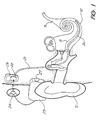
- Known cochlear implants typically consist of two main components, an external component including a speech processor 29, and an internal component including an implanted receiver and stimulator unit 22.
- the external component includes an on-board microphone 27.
- the speech processor 29 is, in this illustration, constructed and arranged so that it can fit behind the outer ear 11. Alternative versions may be worn on the body. Attached to the speech processor 29 is a transmitter coil 24 which transmits electrical signals to the implanted unit 22 via an RF link.
- the implanted component includes a receiver coil 23 for receiving power and data from the transmitter coil 24.
- a cable 21 extends from the implanted receiver and stimulator unit 22 to the cochlea 12 and terminates in an electrode array 20. The signals thus received are applied by the array 20 to the basilar membrane 8 thereby stimulating the auditory nerve 9.
- the operation of such a device is described, for example, in US Patent No. 4,532,930 .
- the sound processor 29 of the cochlear implant can perform an audio spectral analysis of the acoustic signals and outputs channel amplitude levels.
- the sound processor 29 can also sort the outputs in order of magnitude, or flag the spectral maxima as used in the SPEAK strategy developed by Cochlear Ltd.
- FIG. 2 depicts a prior art AGC in use with normal sensitivity control, under two different noise floor conditions.
- the two points on the vertical axis of the graph referred to as T and C correspond to the user's Threshold Level and the user's Comfort level.
- the Threshold level refers to the smallest amount of sound that the user is able to hear and the Comfort level is the upper limit of sound that the user can experience which does not produce an uncomfortably loud sensation.
- a low noise floor level is present, and the response of the AGC is indicated by the left hand locus 21.
- a higher noise floor level is present, with the response of the AGC being indicated by the right hand locus 22.
- the sensitivity has been adjusted so that the threshold level corresponds approximately to the determined noise floor level. Essentially the sensitivity setting determines when the AGC will become active and in both these instances, the AGC becomes active as soon as the sound goes above the noise floor level.
- a linear gain is applied to the input signal between the T and C output levels with the amount of gain being constant in each instance, as can be seen by the gradient of each locus. That is, the higher gain in the first instance is the same for both low input signal levels and high input signal levels, and similarly, the lower gain in the second instance is the same for both low input signal levels and high input signal levels.
- the gain applied to the input signal is relatively higher, to ensure the AGC becomes active as soon as the input sound goes above the noise floor level.
- the gain applied to the input signal is relatively lower, again to ensure that the AGC becomes active as the input sound goes above the noise floor level.
- Figure 3 depicts the gain of an amplifier according to the present invention used in an auditory prosthesis, such as the cochlear implant depicted in Fig. 1 .
- Review of the graph reveals a similar aspect to Fig 2 , in that the amplifier has a linear gain from a relatively low output signal level (threshold T) to a maximum output level at infinite compression C.
- a noise floor estimate is used to determine a lower point through which the slope passes.
- An upper point of the slope is fixed, and defined by the input signal threshold In max at which infinite compression occurs.
- the amplifier according to the present invention applies a differing amount of gain to the input signal, tailored to meet the specific requirements of the sound environment.
- the noise floor estimate is used to set the slope of the AGC response so that the lower end of the AGC response is adjusted to correspond to the determined noise floor.
- the gain control depicted by Figure 3 can be implemented, in one embodiment, using software in a microcontroller (such as is depicted in Figures 4 and 5 ).
- a measurement of the signal amplitude at the output of the gain controlled amplifier is taken where the signal is conveniently high.
- the input signal is then calculated using the known gain set in the amplifier. This is then used to determine the noise floor estimate and as the noise floor varies, the amplifier response is varied in a manner such that input signals at a level equal to the current estimated noise floor value are magnified to an output signal equal to the hearing threshold level T, and the slope of the amplifier response is controlled so that the amplifier response always enters infinite compression at the same point (where the input signal is at, for example, 70dB as in Figure 5 ).
- Tinf is the threshold for infinite compression, corresponding to C.
- Te is the threshold required to result in an audible (T level) stimulation
- x dB is an arbitrary input level
- Emin is the floor noise level
- 70 dB is an example of a fixed input signal threshold at which the amplifier response enters infinite compression.
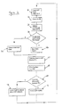
- a level of the output signal is first determined at steps 61 and 62. From that output signal level, the input signal level is then determined by subtracting the gain of the amplifier, at 63. At 64, the determined input level is compared to the lowest level Emin, which is a comparison of the current estimated noise floor value (Emin) with the actual measured input signal level. If the actual input signal level is lower than Emin, the current estimated noise floor level (Emin) is immediately updated to that lower level (at step 65). It can be seen that the "release" time of the current estimated noise floor value (Emin) is essentially zero.
- the current estimated noise floor value (Emin) is raised slightly (at 66).
- the "attack" time of the current estimated noise floor value is slow, typically of the order of five to ten seconds. A slow attack time compensates for those periods in which the input signal level is above the true noise floor, for example when human speech is received by the cochlear implant.
- Output signal level Tx is then calculated as discussed above with reference to Figure 5 (at 67 and 68). Finally, at steps 69 to 71, the adaptive gain is implemented, having a fast attack time (refer to 70), and a relatively slow release time (refer to 71).
- FIG. 7 An alternative gain control method in accordance with the present invention is represented in Figure 7 .
- a point at which the slope of the AGC response changes can be adjusted.
- the slope of the response of the amplifier in this embodiment is linear at a first ratio to a breakpoint and is then linear at a second ratio different to the first ratio until infinite compression commences.
- the position of the breakpoint preferably varies in response to changes in the monitored level of background noise.
- the first ratio is 1:1 and the second ratio is 2:1.
- Other ratios both between and outside these ranges of variation can be envisaged and also it is envisaged that there could be more than one breakpoint between more than two ratios.
- Each of the parallel lines in Figure 7 corresponds to a particular level of the background noise, the noise floor.
- the parallel lines all have a slope of 1:1 in this example, meaning that, on each line no compression is applied when the input signal level is between threshold T and the infinite compression level C.
- Each of these lines intersects either the line indicating levels for which compression of 2:1 is applied, or the horizontal line, which indicates levels at which infinite compression is applied.
- the effective breakpoint varies in response to changes in the estimated level of background noise. Specifically, the breakpoint is increased automatically as the noise floor increases. The breakpoint will remain on the line of 2:1 compression, and approaches the point of infinite compression as the noise floor increases from low values.
- FIG. 8 An example of how this method may be implemented in practice is shown in a block diagram ( Figure 8 ).
- Incoming sounds are detected by a microphone and converted into analog electric signals. These signals are amplified by a pre-amplifier with gain determined by a gain-control signal. The amplified signals pass into an envelope detector. The output of the envelope detector is processed to provide a running estimate of the noise floor level. In addition, the output of the envelope detector is converted into a fast-acting gain-control signal which if applied directly to the gain-controlled preamplifier, would compress the input signal by a ratio of 2:1.
- the estimate of the noise floor is converted into a second gain-control signal which if applied directly to the gain-controlled preamplifier, would cause the background noise to be amplified to a level close to or slightly above the level producing electric stimulation at the T level.
- the rate of change of the gain-control signal derived from the estimated noise floor is much slower than the rate of change of the gain-control signal derived from the envelope detector.
- only one of these two gain-control signals is applied to the pre-amplifier.
- the selected gain-control signal is always that which results in the lower of the two possible pre-amplifier gains.
- the gain-control signal currently applied to the pre-amplifier is passed to the noise-floor estimator.
- the noise-floor estimator may compensate for the particular gain being applied to the microphone signal at all times, so that the estimate refers to the level of noise actually detected by the microphone.
- the noise-floor estimator may obtain its input signal from the microphone via a separate, fixed-gain preamplifier.
- an alternative implementation of the noise-floor estimator may be to generate a signal that tracks the temporal minima in the waveform produced by the envelope detector. For example, when the output of the envelope detector is below the current noise-floor estimate, the noise-floor estimate may be rapidly reduced to equal the envelope level. When the output of the envelope detector is above the current noise-floor estimate, the noise-floor estimate may increase slowly in level.
- the envelope detector may have an attack time, the time taken for the gain to decrease in response to an increase in the background noise level, of less than 5ms and a release time of about 50ms.
- the attack time may be about 10 seconds, while the release time may be near zero.
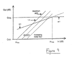
- Figure 9 provides a depiction of the principle of operation of this method. Shown is the relationship between the input (In) and output (Out) signals of the entire AGC scheme for various conditions.
- In min and In max are the minimum and maximum sound pressure levels referred to the microphone input of the speech processor. Typically, In max is about 70 dB SPL, and In min is determined by the electrical noise level internal to the speech-processor circuitry.
- Out T and Out C are the signal levels produced by the AGC circuit that result in electric stimulation at the T-level and C-level, respectively.
- MaximumGain refers to the line on which an input at In min , the internal noise level, produces an output of Out T , causing T-level stimulation.
- the lines labelled 1:1, 2:1, and ⁇ :1 represent linear amplification, 2:1 compression, and infinite compression limiting, respectively.
- the parallel lines represent different linear gains based on the estimated level of the noise floor. These gains reduce, below MaximumGain, for increasing noise-floor levels, represented on the diagram by a shift of the 1:1 line to the right.
- Gain AGC Minimum MaximumGain Gain F Gain L Gain S
- the overall gain, Gain AGC of the entire system at any time is the minimum of the above gain values.
- the implementation of the current embodiment provides that speech or other sounds received at a relatively high level are compressed using a moderate compression ratio, for example 2:1, and short time constants, improving the understanding of speech for users of hearing devices.
- the level of background noise is tracked relatively slowly by the noise-floor estimator, and is used to set the pre-amplifier gain such that the noise will usually be perceived as comparatively soft by device users, avoiding the problem of background noise being perceived to have excessive loudness when a progressive compressor with a fixed compression ratio is used in a hearing device speech processor.
- Excessive sound levels always receive infinite compression, and are converted to electric stimulation at the C-level, so they should never be perceived to have uncomfortable loudness.
- the implementation is efficient and is based on a small number of previously developed signal processing functions.
Landscapes
- Health & Medical Sciences (AREA)
- General Health & Medical Sciences (AREA)
- Otolaryngology (AREA)
- Neurosurgery (AREA)
- Physics & Mathematics (AREA)
- Engineering & Computer Science (AREA)
- Acoustics & Sound (AREA)
- Signal Processing (AREA)
- Control Of Amplification And Gain Control (AREA)
Claims (73)
- Verstärker zur Bereitstellung eines anpassbaren Betriebs einer Gehörprothese, wobei der Verstärker betreibbar ist, ein Eingangssignal zu empfangen und ein Ausgangssignal zu erzeugen, wobei der Verstärker Folgendes umfasst:eine Verstärkungssteuerungseinrichtung; undeine Einrichtung zum Bereitstellen eines aktuellen geschätzten Rauschhintergrundwertes (Emin) des Eingangssignals,wobei in Reaktion auf eine Änderung des aktuellen geschätzten Rauschhintergrundwertes (Emin) die Verstärkungssteuerungseinrichtung betreibbar ist, den Verstärkungsbetrag, der auf das Eingangssignal angewendet wird, zu ändern, undwobei in Reaktion auf eine Änderung des aktuellen geschätzten Rauschhintergrundwerts (Emin) die Verstärkungssteuerungseinrichtung betreibbar ist, ein Verstärkungskompressionsverhältnis des Verstärkers über zumindest einen Teil des dynamischen Bereiches des Verstärkers zu ändern.
- Verstärker nach Anspruch 1, wobei der aktuelle geschätzte Rauschhintergrundwert (Emin) aus dem Eingangssignal abgeleitet wird.
- Verstärker nach Anspruch 1 oder Anspruch 2, wobei der aktuelle geschätzte Rauschhintergrundwert (Emin) im Wesentlichen kontinuierlich aktualisiert wird.
- Verstärker nach Anspruch 1 oder Anspruch 2, wobei der aktuelle geschätzte Rauschhintergrundwert (Emin) periodisch aktualisiert wird.
- Verstärker nach Anspruch 2, wobei der aktuelle geschätzte Rauschhintergrundwert (Emin) aus dem Eingangssignal abgeleitet wird, indem eine Hüllkurve des Eingangssignals überwacht wird und der aktuelle geschätzte Rauschhintergrundwert (Emin) basierend auf erfassten Minima der Hüllkurve bestimmt wird.
- Verstärker nach irgendeinem der Ansprüche 1 bis 5, wobei der Verstärker konfiguriert ist, unendliche Kompression des Eingangssignals über einen maximalen Komfortwert (C) bereitzustellen.
- Verstärker nach irgendeinem der Ansprüche 1 bis 6, wobei ein dynamischer Bereich des Verstärkers in Reaktion auf eine Verringerung des aktuellen geschätzten Rauschhintergrundwerts (Emin) erhöht wird.
- Verstärker nach irgendeinem der Ansprüche 1 bis 7, wobei ein dynamischer Bereich des Verstärkers in Reaktion auf eine Erhöhung des aktuellen geschätzten Rauschhintergrundwerts (Emin) verkleinert wird.
- Verstärker nach irgendeinem der Ansprüche 1 bis 8, wobei die Verstärkerantwort nach der Änderung des Verstärkerkompressionsverhältnisses kontinuierlich, monoton und anwachsend für alle Ausgangssignallevel (Tx) zwischen einem Hörschwellwertbetrag (T) eines Benutzers und einem maximalen Komfortwert (C) des Benutzers ist.
- Verstärker nach irgendeinem der Ansprüche 1 bis 9, wobei der Verstärker ein Ausgangssignal erzeugt, das im Wesentlichen gleich der Größe des HörschwellwertbetragHörschwellwertbetrages (T) eines Benutzers ist, wenn das Eingangssignal im Wesentlichen gleich dem aktuellen geschätzten Rauschhintergrundwertes (Emin) ist.
- Verstärker nach irgendeinem der Ansprüche 1 bis 10, wobei die Verstärkungssteuerungseinrichtung sicherstellt, dass der Verstärker nach dem Ändern des Verstärkungskompressionsverhältnisses keinerlei Ausgangssignale erzeugt, die einen maximalen Komfortlevel (C) eines Benutzers übersteigen.
- Verstärker nach Anspruch 11, wobei der Verstärker einen konstanten Ausgangssignallevel (Tx) für alle Eingangssignallevel (x) oberhalb eines maximalen Eingangslevels erzeugt.
- Verstärker nach Anspruch 12, wobei der maximale Eingangslevel im Bereich 60-90 dB liegt.
- Verstärker nach Anspruch 13, wobei der maximale Eingangslevel im Wesentlichen 70 dB ist.
- Verstärker nach einem der Ansprüche 1 bis 14, wobei die Verstärkungssteuerungseinrichtung den Verstärker so steuert, dass er eine im Wesentlichen Nullverstärkung für Eingangssignale unterhalb des aktuellen geschätzten Rauschhintergrundwerts (Emin) aufweist, so dass im Wesentlichen kein Ausgangssignal produziert wird, wenn Eingangssignale bei solchen Leveln von dem Verstärker empfangen werden.
- Verstärker nach irgendeinem der Ansprüche 1 bis 14, wobei die Verstärkungssteuerungseinrichtung den Verstärker so steuert, dass er eine im Wesentlichen konstante Verstärkung für Eingangssignale unterhalb des aktuellen geschätzten Rauschhintergrundwerts (Emin) aufweist.
- Verstärker nach irgendeinem der Ansprüche 1 bis 16, wobei der Verstärker zur Bereitstellung eines adaptiven Betriebs einer Hörhilfe vorgesehen ist.
- Verstärker nach irgendeinem der Ansprüche 1 bis 16, wobei der Verstärker zur Bereitstellung eines adaptiven Betriebs für ein Gehörschneckenimplantat vorgesehen ist.
- Verstärker nach irgendeinem der Ansprüche 1 bis 18, wobei eine Steigung der Verstärkerantwort im dynamischen Bereich des Verstärkers in Reaktion auf einen Abfall des überwachten Levels des Hintergrundrauschens erniedrigt wird.
- Verstärker nach Anspruch 19, wobei bei einer Wahrnehmung eines moderaten Levels eines Hintergrundrauschens das Verstärkungskompressionsverhältnis des Verstärkers im Wesentlichen auf 1:1 über den dynamischen Bereich eingestellt wird.
- Verstärker nach Anspruch 20, wobei, wenn der Level des Hintergrundrauschens kleiner als der wahrgenommene moderate Level ist, das Verstärkungskompressionsverhältnis im Wesentlichen auf 2:1 über den dynamischen Bereich eingestellt wird.
- Verstärker nach irgendeinem der Ansprüche 1 bis 21, wobei ein Eingangssignallevel, bei dem der Verstärker unendliche Kompression erreicht, derselbe ist, unabhängig von der Steigung der Verstärkung der Verstärkereinrichtung.
- Verstärker nach irgendeinem der Ansprüche 1 bis 22, wobei eine Steigung der Verstärkerantwort im dynamischen Bereich nicht linear ist.
- Verstärker nach Anspruch 23, wobei die Nichtlinearität der Steigung der Verstärkerantwort im dynamischen Bereich in Reaktion auf Änderungen des aktuellen geschätzten Rauschhintergrundwertes (Emin) variiert.
- Verstärker nach Anspruch 23 oder Anspruch 24, wobei mit wachsendem Eingangssignallevel die Steigung der Verstärkerantwort im dynamischen Bereich bei einem ersten Verhältnis linear ist bis zu einem Knickpunkt und dann bei einem zweiten Verhältnis, das unterschiedlich zu dem ersten Verhältnis ist, linear bis zur unendlichen Kompression ist.
- Verstärker nach Anspruch 25, wobei eine Vielzahl von Knickpunkten über den dynamischen Bereich des Verstärkers auftreten.
- Verstärker nach Anspruch 25 oder Anspruch 26, wobei die Steigung der Verstärkerantwort für kleinere Eingangssignallevel größer ist, und reduziert wird für Eingangssignallevel über einem Knickpunkt oder einem ersten Knickpunkt, so dass Eingangssignale, die bei einem Level über dem Knickpunkt empfangen werden, zum Teil komprimiert werden, relativ zu Eingangssignalen bei einem Level unter dem Knickpunkt.
- Verstärker nach irgendeinem der Ansprüche 25 bis 27, wobei eine Position des Knickpunkts in dem dynamischen Bereich in Reaktion auf Änderungen des aktuellen geschätzten Rauschhintergrundwertes (Emin) variiert.
- Verstärker nach Anspruch 25, wobei das erste Verhältnis im Wesentlichen 1:1 ist und das zweite Verhältnis im Wesentlichen 2:1 ist.
- Verstärker nach irgendeinem der Ansprüche 1 bis 29, wobei der Verstärker gesteuert werden kann, ein Ausgangssignal zu erzeugen, das größer als ein maximaler Komfortlevel (C) eines Benutzers ist.
- Verstärker nach irgendeinem der Ansprüche 1 bis 30, wobei der aktuelle geschätzte Rauschhintergrundwert (Emin) bestimmt wird durch Überwachen eines kleinsten Signallevels, das in dem Eingangssignal innerhalb einer vorangegangenen Zeitperiode beobachtet wird.
- Verstärker nach Anspruch 31, wobei die Zeitperiode in der Größenordnung von Sekunden ist, um natürliche Unterbrechungen in der Konversation zu erlauben.
- Verstärker nach Anspruch 31 oder Anspruch 32, wobei, wenn ein beobachteter kleinster Signallevel in der vorangegangenen Zeitperiode kleiner ist als der aktuelle geschätzte Rauschhintergrundwert (Emin), der aktuelle geschätzte Rauschhintergrundwert (Emin) auf den neuen niedrigeren Level geändert wird.
- Verstärker nach irgendeinem der Ansprüche 31 bis 33, wobei, wenn ein beobachtetes niedrigstes Signallevel in der vorangegangenen Zeitperiode größer ist als der aktuelle geschätzte Rauschhintergrundwert (Emin), die aktuelle Rauschhintergrundsschätzung geringfügig in Richtung des beobachteten niedrigsten Signallevels erhöht wird.
- Verstärker nach irgendeinem der Ansprüche 1 bis 34, wobei die Verstärkungssteuerungseinrichtung unter Verwendung von Software, die von einem Mikrocontroller ausgeführt wird, umgesetzt ist.
- Verfahren zum Steuern der Verstärkung einer Verstärkungseinrichtung einer Gehörprothese, wobei die Verstärkungseinrichtung betreibbar ist, ein Eingangssignal zu empfangen und ein Ausgangssignal zu erzeugen, wobei das Verfahren folgende Schritte umfasst:Bestimmen (64, 65, 66) eines aktuellen geschätzten Rauschhintergrundwerts (Emin);in Reaktion auf eine Änderung des aktuellen geschätzten Rauschhintergrundwerts (Emin), Ändern (69, 70, 71) der Verstärkung, die auf das Eingangssignal durch die Verstärkungseinrichtung angewendet wird; undin Reaktion auf die Änderung des aktuellen geschätzten Rauschhintergrundwerts (Emin), Ändern eines Verstärkungskompressionsverhältnisses über mindestens einen Teil eines dynamischen Bereichs der Verstärkungseinrichtung.
- Verfahren nach Anspruch 36, wobei der Schritt des Änderns der Verstärkung die Sicherstellung umfasst, dass alle Eingangssignale, die im Wesentlichen gleich oder über dem aktuellen geschätzten Rauschhintergrundwert (Emin) sind, in ein Ausgangssignal umgewandelt werden, das im Wesentlichen gleich zu oder über einem HörschwellwertbetragHörschwellwertbetrag (T) ist.
- Verfahren nach Anspruch 36 oder Anspruch 37, wobei der Schritt des Änderns der Verstärkung das Beibehalten gewünschter Verstärkungscharakteristiken des Verstärkers über einen Bereich von Eingangssignalleveln umfasst.
- Verfahren nach einem der Ansprüche 36 bis 38, wobei der Schritt des Bestimmens des aktuellen geschätzten Rauschhintergrundwerts (Emin) das Ableiten (61-66) des aktuellen geschätzten Rauschhintergrundwerts (Emin) aus dem Ausgangssignal umfasst.
- Verfahren nach irgendeinem der Ansprüche 36 bis 39, wobei der Schritt des Bestimmens des aktuellen geschätzten Rauschhintergrundwerts (Emin) im Wesentlichen kontinuierlich durchgeführt wird.
- Verfahren nach irgendeinem der Ansprüche 36 bis 39, wobei der Schritt des Bestimmens des aktuellen geschätzten Rauschhintergrundwerts (Emin) periodisch durchgeführt wird.
- Verfahren nach irgendeinem der Ansprüche 36 bis 41, wobei der Verstärker konfiguriert ist, unendliche Kompression des Eingangssignals oberhalb eines maximalen Komfortwertes (C) bereitzustellen.
- Verfahren nach irgendeinem der Ansprüche 36 bis 42, wobei der Schritt des Bestimmens des aktuellen geschätzten Rauschhintergrundwerts (Emin) das Überwachen einer Hüllkurve des Eingangssignals und das Bestimmen des aktuellen geschätzten Rauschhintergrundwerts (Emin) basierend auf erfassten Minima der Hüllkurve umfasst.
- Verfahren nach irgendeinem der Ansprüche 36 bis 43, wobei der Schritt des Änderns der Verstärkung das Anwenden unterschiedlicher Verstärkung für unterschiedliche Eingangssignallevel umfasst, so dass die Verstärkerantwort nicht linear für die Änderung von Eingangssignallevel (x) ist.
- Verfahren nach irgendeinem der Ansprüche 36 bis 44, wobei der Schritt des Änderns der Verstärkung ein Erhöhen des dynamischen Bereichs des Verstärkers in Reaktion auf eine Erniedrigung des aktuellen geschätzten Rauschhintergrundwerts (Emin) umfasst.
- Verfahren nach irgendeinem der Ansprüche 36 bis 45, wobei der Schritt des Änderns der Verstärkung ein Erniedrigen des dynamischen Bereiches des Verstärkers in Reaktion auf eine Erhöhung des aktuellen geschätzten Rauschhintergrundwerts (Emin) umfasst.
- Verfahren nach irgendeinem der Ansprüche 36 bis 46, wobei der Schritt des Änderns der Verstärkung nach der Änderung des Verstärkungskompressionsverhältnisses eine Verstärkerantwort bereitstellt, die kontinuierlich, monoton und anwachsend für alle Ausgangssignallevel (Tx) zwischen einem Hörschwellwertbetrag (T) und einem maximalen Komfortwert (C) ist.
- Verfahren nach irgendeinem der Ansprüche 36 bis 47, wobei der Schritt des Änderns der Verstärkung ein Ändern der Verstärkung umfasst, so dass der Verstärker ein Ausgangssignal (Tx) erzeugt, das im Wesentlichen gleich groß wie ein Hörschwellwertbetrag (T) ist, wenn das Eingangssignal im Wesentlichen gleich dem aktuellen geschätzten Rauschhintergrundwert (Emin) ist.
- Verfahren nach irgendeinem der Ansprüche 36 bis 48, wobei der Schritt des Änderns der Verstärkung das Ändern der Verstärkung umfasst, so dass der Verstärker nach der Änderung des Verstärkungskompressionsverhältnisses keinerlei Ausgangssignale erzeugt, die einen maximalen Komfortlevel (C) überschreiten, selbst wenn das Eingangssignal bei hohen Leveln liegt.
- Verfahren nach Anspruch 49, wobei der Schritt des Änderns der Verstärkung die Änderung der Verstärkung umfasst, so dass der Verstärker ein konstantes Ausgangssignallevel für alle Eingangssignallevel oberhalb einem maximalen Eingangslevel erzeugt.
- Verfahren nach Anspruch 50, wobei der maximale Eingangslevel im Bereich 60-90 dB liegt.
- Verfahren nach Anspruch 51, wobei der maximale Eingangslevel im Wesentlichen 70 dB ist.
- Verfahren nach irgendeinem der Ansprüche 36 bis 52, wobei der Schritt des Änderns der Verstärkung das Ändern der Verstärkung umfasst, so dass der Verstärker im Wesentlichen Nullverstärkung für Eingangssignale unterhalb des aktuellen geschätzten Rauschhintergrundwerts (Emin) hat, so dass im Wesentlichen kein Ausgangssignal erzeugt wird, wenn Eingangssignale bei solchen Leveln von dem Verstärker empfangen werden.
- Verfahren nach irgendeinem der Ansprüche 36 bis 52, wobei der Schritt des Änderns der Verstärkung das Ändern der Verstärkung umfasst, so dass die Verstärkung des Verstärkers für Eingangssignale unterhalb des aktuellen geschätzten Rauschhintergrundwerts (Emin) konstant gehalten wird.
- Verfahren nach irgendeinem der Ansprüche 36 bis 54, wobei die Gehörprothese eine Hörhilfe ist.
- Verfahren nach irgendeinem der Ansprüche 36 bis 54, wobei die Gehörprothese ein Gehörschneckenimplantat ist.
- Verfahren nach irgendeinem der Ansprüche 36 bis 56, wobei der Schritt des Änderns der Verstärkung die Änderung der Verstärkung umfasst, so dass die Verstärkungseinrichtung eine lineare Verstärkung der Eingangssignale bereitstellt, die eine größere Amplitude, als der aktuelle geschätzte Rauschhintergrundwert (Emin) und eine kleinere Amplitude als ein maximaler Eingangssignallevel aufweisen.
- Verfahren nach irgendeinem der Ansprüche 36 bis 57, wobei der Schritt des Änderns der Verstärkung das Ändern der Verstärkung umfasst, so dass eine Steigung der Verstärkerantwort in Reaktion auf eine Erniedrigung des aktuellen geschätzten Rauschhintergrundwerts (Emin) verkleinert wird.
- Verfahren nach irgendeinem der Ansprüche 36 bis 58, wobei der Schritt des Änderns der Verstärkung die Änderung der Verstärkung umfasst, so dass bei einem wahrgenommenen moderaten Level des aktuellen geschätzten Rauschhintergrundwerts (Emin) die Verstärkung auf ein Verhältnis von im Wesentlichen 1:1 1 über einen dynamischen Bereich des Verstärkers eingestellt wird.
- Verfahren nach Anspruch 59, wobei der Schritt des Änderns der Verstärkung die Änderung der Verstärkung umfasst, so dass zu Zeiten, wenn der aktuellen geschätzte Rauschhintergrundwert (Emin) kleiner als der wahrgenommene moderate Level ist, die Verstärkung auf ein Verhältnis von im Wesentlichen 2:1 über den dynamischen Bereich des Verstärkers eingestellt wird.
- Verfahren nach irgendeinem der Ansprüche 36 bis 60, wobei der Schritt des Änderns der Verstärkung das Verändern der Verstärkung umfasst, so dass ein Eingangssignallevel, bei dem der Verstärker unendliche Kompression erreicht, derselbe ist, unabhängig von dem aktuellen geschätzten Rauschhintergrundwert (Emin).
- Verfahren nach irgendeinem der Ansprüche 36 bis 61, wobei der Schritt des Änderns der Verstärkung die Änderung der Verstärkung umfasst, so dass die Steigung der Verstärkerantwort im dynamischen Bereich nichtlinear ist.
- Verfahren nach Anspruch 62, wobei die Nichtlinearität der Steigung der Verstärkerantwort im dynamischen Bereich in Reaktion auf Änderungen des aktuellen geschätzten Rauschhintergrundwerts (Emin) variiert.
- Verfahren nach Anspruch 62 oder Anspruch 63, wobei die Steigung der Verstärkerantwort mit wachsendem Eingangssignallevel bei einem ersten Verhältnis bis zu einem Knickpunkt linear ist und dann bei einem zweiten Verhältnis, das unterschiedlich zum ersten Verhältnis ist, linear ist bis zur unbegrenzten Kompression.
- Verfahren nach Anspruch 64, wobei eine Vielzahl von Knickpunkten in der Verstärkerantwort existiert.
- Verfahren nach irgendeinem der Ansprüche 62 bis 65, wobei die Steigung der Verstärkerantwort für kleinere Eingangssignallevel größer ist und für Eingangssignallevel über dem Knickpunkt oder dem ersten Knickpunkt reduziert wird.
- Verfahren nach irgendeinem der Ansprüche 62 bis 66, wobei die Position des Knickpunkts in Reaktion auf Änderungen des aktuellen geschätzten Rauchhintergrundwerts (Emin) variiert.
- Verfahren nach Anspruch 64, wobei das erste Verhältnis im Wesentlichen 1:1 und das zweite Verhältnis im Wesentlichen 2:1 ist.
- Verfahren nach Anspruch 64, wobei in Reaktion auf eine Erniedrigung des aktuellen geschätzten Rauschhintergrundwerts (Emin) der Knickpunkt im dynamischen Bereich der Verstärkerantwort nach unten bewegt wird.
- Verfahren nach irgendeinem der Ansprüche 36 bis 69, wobei der Schritt der Bestimmung des aktuellen geschätzten Rauschhintergrundwerts (Emin) das Nachführen des niedrigsten Signallevels, das in dem Eingangssignal über eine vorangegangene Zeitperiode beobachtet wurde, umfasst.
- Verfahren nach Anspruch 70, wobei die vorangegangene Zeitperiode in der Größenordnung einer Anzahl von Sekunden ist, um natürliche Unterbrechungen in der Konversation zu erlauben.
- Verfahren nach Anspruch 70 oder Anspruch 71, wobei, wenn (64) der niedrigste Signallevel, der während der vorangegangenen Zeitperiode beobachtet wurde, niedriger ist als der aktuelle geschätzte Rauschhintergrundwert (Emin), der aktuelle geschätzte Rauschhintergrundwert (Emin) auf einen niedrigeren Level aktualisiert wird (65).
- Verfahren nach irgendeinem der Ansprüche 70 bis 72, wobei, wenn (64) der niedrigste Signallevel, der während der vorangegangenen Zeitperiode beobachtet wurde, größer ist als der aktuelle geschätzte Rauschhintergrundwert (Emin) ist, der aktuelle geschätzte Rauschhintergrundwert (Emin) etwas in Richtung des niedrigsten beobachteten Signallevels erhöht wird (66).
Applications Claiming Priority (3)
| Application Number | Priority Date | Filing Date | Title |
|---|---|---|---|
| AUPR438601 | 2001-04-11 | ||
| AUPR4386A AUPR438601A0 (en) | 2001-04-11 | 2001-04-11 | Variable sensitivity control for a cochlear implant |
| PCT/AU2002/000463 WO2002084866A1 (en) | 2001-04-11 | 2002-04-11 | Variable sensitivity control for a cochlear implant |
Publications (3)
| Publication Number | Publication Date |
|---|---|
| EP1384319A1 EP1384319A1 (de) | 2004-01-28 |
| EP1384319A4 EP1384319A4 (de) | 2010-06-02 |
| EP1384319B1 true EP1384319B1 (de) | 2013-09-04 |
Family
ID=3828382
Family Applications (1)
| Application Number | Title | Priority Date | Filing Date |
|---|---|---|---|
| EP02713943.5A Expired - Lifetime EP1384319B1 (de) | 2001-04-11 | 2002-04-11 | Variable empfindlichkeitssteuerung für ein innenohrimplantat |
Country Status (4)
| Country | Link |
|---|---|
| US (1) | US7522960B2 (de) |
| EP (1) | EP1384319B1 (de) |
| AU (1) | AUPR438601A0 (de) |
| WO (1) | WO2002084866A1 (de) |
Families Citing this family (26)
| Publication number | Priority date | Publication date | Assignee | Title |
|---|---|---|---|---|
| ES2360341T3 (es) | 1997-02-11 | 2011-06-03 | Enterprise Ireland (Trading As Bioresearch Ireland) | Cepas probióticas de lactobacillus salivarius y agentes antimicrobianos obtenidos a partir de las mismas. |
| US7155385B2 (en) * | 2002-05-16 | 2006-12-26 | Comerica Bank, As Administrative Agent | Automatic gain control for adjusting gain during non-speech portions |
| US7489901B2 (en) * | 2004-09-30 | 2009-02-10 | Alcatel-Lucent Usa Inc. | Method for dynamically estimating noise floor and rise over thermal (ROT) |
| US8086451B2 (en) * | 2005-04-20 | 2011-12-27 | Qnx Software Systems Co. | System for improving speech intelligibility through high frequency compression |
| US8249861B2 (en) * | 2005-04-20 | 2012-08-21 | Qnx Software Systems Limited | High frequency compression integration |
| US20080069385A1 (en) * | 2006-09-18 | 2008-03-20 | Revitronix | Amplifier and Method of Amplification |
| US9352154B2 (en) | 2007-03-22 | 2016-05-31 | Cochlear Limited | Input selection for an auditory prosthesis |
| US9049524B2 (en) * | 2007-03-26 | 2015-06-02 | Cochlear Limited | Noise reduction in auditory prostheses |
| US8641595B2 (en) * | 2008-01-21 | 2014-02-04 | Cochlear Limited | Automatic gain control for implanted microphone |
| EP2297977A4 (de) * | 2008-05-30 | 2013-03-20 | Cochlear Ltd | Verfahren und vorrichtung zur akustischen verarbeitung |
| US20100318353A1 (en) * | 2009-06-16 | 2010-12-16 | Bizjak Karl M | Compressor augmented array processing |
| US8976981B2 (en) * | 2010-10-07 | 2015-03-10 | Blackberry Limited | Circuit, system and method for isolating a transducer from an amplifier in an electronic device |
| US8787608B2 (en) | 2011-05-24 | 2014-07-22 | Cochlear Limited | Vibration isolation in a bone conduction device |
| US10419861B2 (en) | 2011-05-24 | 2019-09-17 | Cochlear Limited | Convertibility of a bone conduction device |
| WO2012161717A1 (en) | 2011-05-26 | 2012-11-29 | Advanced Bionics Ag | Systems and methods for improving representation by an auditory prosthesis system of audio signals having intermediate sound levels |
| US8762088B2 (en) * | 2012-01-30 | 2014-06-24 | Jds Uniphase Corporation | MoCA quality index measurement system for qualifying home networks |
| KR102037551B1 (ko) | 2012-03-04 | 2019-10-28 | 퀀탄스, 인코포레이티드 | 지연 보정을 갖는 포락선 추적 전력 증폭 시스템 |
| US9049527B2 (en) | 2012-08-28 | 2015-06-02 | Cochlear Limited | Removable attachment of a passive transcutaneous bone conduction device with limited skin deformation |
| US9314624B2 (en) * | 2013-01-17 | 2016-04-19 | Cochlear Limited | Systems and methods for altering the input dynamic range of an auditory device |
| EP2974005B1 (de) | 2013-03-14 | 2018-06-20 | Quantance, Inc. | Et-system mit rauschanpassung |
| US9270239B2 (en) | 2013-03-15 | 2016-02-23 | Quantance, Inc. | Envelope tracking system with internal power amplifier characterization |
| US9992584B2 (en) * | 2015-06-09 | 2018-06-05 | Cochlear Limited | Hearing prostheses for single-sided deafness |
| DE102015211745A1 (de) * | 2015-06-24 | 2016-12-29 | Sivantos Pte. Ltd. | Verfahren zur Kompression der Dynamik in einem Audio-Signal |
| US9782586B2 (en) * | 2015-08-27 | 2017-10-10 | iMEDI PLUS Inc. | Signal processing method in cochlear implant |
| EP3276825B1 (de) | 2016-07-27 | 2021-05-26 | Nxp B.V. | Verstärkungskalibrierungssteuereinheit |
| WO2021058506A1 (en) * | 2019-09-27 | 2021-04-01 | Widex A/S | A method of operating an ear level audio system and an ear level audio system |
Family Cites Families (11)
| Publication number | Priority date | Publication date | Assignee | Title |
|---|---|---|---|---|
| US4532930A (en) * | 1983-04-11 | 1985-08-06 | Commonwealth Of Australia, Dept. Of Science & Technology | Cochlear implant system for an auditory prosthesis |
| US4630305A (en) * | 1985-07-01 | 1986-12-16 | Motorola, Inc. | Automatic gain selector for a noise suppression system |
| US4792977A (en) * | 1986-03-12 | 1988-12-20 | Beltone Electronics Corporation | Hearing aid circuit |
| US4852175A (en) | 1988-02-03 | 1989-07-25 | Siemens Hearing Instr Inc | Hearing aid signal-processing system |
| US5329243A (en) | 1992-09-17 | 1994-07-12 | Motorola, Inc. | Noise adaptive automatic gain control circuit |
| GB2289583B (en) | 1994-05-04 | 1999-06-23 | Gilden Research Ltd | Adaptive audio system |
| GB2292275A (en) | 1994-08-11 | 1996-02-14 | Original Passenger Picture Sho | Control of sound level in dependence on ambient noise |
| AUPM900594A0 (en) * | 1994-10-24 | 1994-11-17 | Cochlear Pty. Limited | Automatic sensitivity control |
| US5907622A (en) * | 1995-09-21 | 1999-05-25 | Dougherty; A. Michael | Automatic noise compensation system for audio reproduction equipment |
| JPH10303665A (ja) | 1997-04-30 | 1998-11-13 | Matsushita Electric Ind Co Ltd | 自動利得制御回路 |
| AU8050998A (en) * | 1997-06-16 | 1999-01-04 | Telefonaktiebolaget Lm Ericsson (Publ) | Method and apparatus for low complexity noise reduction |
-
2001
- 2001-04-11 AU AUPR4386A patent/AUPR438601A0/en not_active Abandoned
-
2002
- 2002-04-11 EP EP02713943.5A patent/EP1384319B1/de not_active Expired - Lifetime
- 2002-04-11 WO PCT/AU2002/000463 patent/WO2002084866A1/en not_active Ceased
- 2002-04-11 US US10/474,631 patent/US7522960B2/en not_active Expired - Lifetime
Also Published As
| Publication number | Publication date |
|---|---|
| AUPR438601A0 (en) | 2001-05-17 |
| WO2002084866A1 (en) | 2002-10-24 |
| EP1384319A1 (de) | 2004-01-28 |
| EP1384319A4 (de) | 2010-06-02 |
| US7522960B2 (en) | 2009-04-21 |
| US20040172242A1 (en) | 2004-09-02 |
Similar Documents
| Publication | Publication Date | Title |
|---|---|---|
| US7522960B2 (en) | Variable sensitivity control for a cochlear implant | |
| US8532317B2 (en) | Programmable auditory prosthesis with trainable automatic adaptation to acoustic conditions | |
| US11596793B2 (en) | Shifting of output in a sense prosthesis | |
| US10463476B2 (en) | Body noise reduction in auditory prostheses | |
| US6970570B2 (en) | Hearing aids based on models of cochlear compression using adaptive compression thresholds | |
| US7978868B2 (en) | Adaptive dynamic range optimization sound processor | |
| US6496734B1 (en) | Auditory prosthesis with automated voice muting using the stapedius muscle reflex | |
| US9553557B2 (en) | Post-filter common-gain determination | |
| EP0253612A2 (de) | Hörgeräte | |
| US10525265B2 (en) | Impulse noise management | |
| CA2486893C (en) | Programmable auditory prosthesis with trainable automatic adaptation to acoustic conditions | |
| JP3868422B2 (ja) | 補聴器および音声信号の処理方法 | |
| US9780747B2 (en) | Feature-based level control using loudness growth functions | |
| US8605925B2 (en) | Acoustic processing method and apparatus | |
| WO2018171858A1 (en) | Bimodal hearing stimulation system | |
| US11589170B2 (en) | Generalized method for providing one or more stimulation coding parameters in a hearing aid system for obtaining a perceivable hearing loudness | |
| AU2002245950B2 (en) | Variable sensitivity control for a cochlear implant | |
| AU2002245950A1 (en) | Variable sensitivity control for a cochlear implant | |
| US10492007B2 (en) | Impulse-aware sound processing | |
| AU2004240216B2 (en) | Programmable Auditory Prosthesis with Trainable Automatic Adaptation to Acoustic Conditions |
Legal Events
| Date | Code | Title | Description |
|---|---|---|---|
| PUAI | Public reference made under article 153(3) epc to a published international application that has entered the european phase |
Free format text: ORIGINAL CODE: 0009012 |
|
| 17P | Request for examination filed |
Effective date: 20031103 |
|
| AK | Designated contracting states |
Kind code of ref document: A1 Designated state(s): AT BE CH CY DE DK ES FI FR GB GR IE IT LI LU MC NL PT SE TR |
|
| AX | Request for extension of the european patent |
Extension state: AL LT LV MK RO SI |
|
| A4 | Supplementary search report drawn up and despatched |
Effective date: 20100506 |
|
| 17Q | First examination report despatched |
Effective date: 20110307 |
|
| GRAP | Despatch of communication of intention to grant a patent |
Free format text: ORIGINAL CODE: EPIDOSNIGR1 |
|
| INTG | Intention to grant announced |
Effective date: 20130405 |
|
| GRAS | Grant fee paid |
Free format text: ORIGINAL CODE: EPIDOSNIGR3 |
|
| GRAA | (expected) grant |
Free format text: ORIGINAL CODE: 0009210 |
|
| AK | Designated contracting states |
Kind code of ref document: B1 Designated state(s): AT BE CH CY DE DK ES FI FR GB GR IE IT LI LU MC NL PT SE TR |
|
| REG | Reference to a national code |
Ref country code: GB Ref legal event code: FG4D |
|
| REG | Reference to a national code |
Ref country code: CH Ref legal event code: EP |
|
| REG | Reference to a national code |
Ref country code: AT Ref legal event code: REF Ref document number: 630970 Country of ref document: AT Kind code of ref document: T Effective date: 20130915 |
|
| REG | Reference to a national code |
Ref country code: IE Ref legal event code: FG4D |
|
| REG | Reference to a national code |
Ref country code: DE Ref legal event code: R096 Ref document number: 60245471 Country of ref document: DE Effective date: 20131031 |
|
| REG | Reference to a national code |
Ref country code: AT Ref legal event code: MK05 Ref document number: 630970 Country of ref document: AT Kind code of ref document: T Effective date: 20130904 |
|
| REG | Reference to a national code |
Ref country code: NL Ref legal event code: VDEP Effective date: 20130904 |
|
| PG25 | Lapsed in a contracting state [announced via postgrant information from national office to epo] |
Ref country code: SE Free format text: LAPSE BECAUSE OF FAILURE TO SUBMIT A TRANSLATION OF THE DESCRIPTION OR TO PAY THE FEE WITHIN THE PRESCRIBED TIME-LIMIT Effective date: 20130904 Ref country code: CY Free format text: LAPSE BECAUSE OF FAILURE TO SUBMIT A TRANSLATION OF THE DESCRIPTION OR TO PAY THE FEE WITHIN THE PRESCRIBED TIME-LIMIT Effective date: 20130619 Ref country code: AT Free format text: LAPSE BECAUSE OF FAILURE TO SUBMIT A TRANSLATION OF THE DESCRIPTION OR TO PAY THE FEE WITHIN THE PRESCRIBED TIME-LIMIT Effective date: 20130904 |
|
| REG | Reference to a national code |
Ref country code: NL Ref legal event code: VDEP Effective date: 20130904 |
|
| PG25 | Lapsed in a contracting state [announced via postgrant information from national office to epo] |
Ref country code: FI Free format text: LAPSE BECAUSE OF FAILURE TO SUBMIT A TRANSLATION OF THE DESCRIPTION OR TO PAY THE FEE WITHIN THE PRESCRIBED TIME-LIMIT Effective date: 20130904 Ref country code: GR Free format text: LAPSE BECAUSE OF FAILURE TO SUBMIT A TRANSLATION OF THE DESCRIPTION OR TO PAY THE FEE WITHIN THE PRESCRIBED TIME-LIMIT Effective date: 20131205 |
|
| PG25 | Lapsed in a contracting state [announced via postgrant information from national office to epo] |
Ref country code: BE Free format text: LAPSE BECAUSE OF FAILURE TO SUBMIT A TRANSLATION OF THE DESCRIPTION OR TO PAY THE FEE WITHIN THE PRESCRIBED TIME-LIMIT Effective date: 20130904 Ref country code: CY Free format text: LAPSE BECAUSE OF FAILURE TO SUBMIT A TRANSLATION OF THE DESCRIPTION OR TO PAY THE FEE WITHIN THE PRESCRIBED TIME-LIMIT Effective date: 20130904 |
|
| PG25 | Lapsed in a contracting state [announced via postgrant information from national office to epo] |
Ref country code: NL Free format text: LAPSE BECAUSE OF FAILURE TO SUBMIT A TRANSLATION OF THE DESCRIPTION OR TO PAY THE FEE WITHIN THE PRESCRIBED TIME-LIMIT Effective date: 20130904 |
|
| PG25 | Lapsed in a contracting state [announced via postgrant information from national office to epo] |
Ref country code: ES Free format text: LAPSE BECAUSE OF FAILURE TO SUBMIT A TRANSLATION OF THE DESCRIPTION OR TO PAY THE FEE WITHIN THE PRESCRIBED TIME-LIMIT Effective date: 20130904 |
|
| REG | Reference to a national code |
Ref country code: DE Ref legal event code: R097 Ref document number: 60245471 Country of ref document: DE |
|
| PG25 | Lapsed in a contracting state [announced via postgrant information from national office to epo] |
Ref country code: PT Free format text: LAPSE BECAUSE OF FAILURE TO SUBMIT A TRANSLATION OF THE DESCRIPTION OR TO PAY THE FEE WITHIN THE PRESCRIBED TIME-LIMIT Effective date: 20140106 |
|
| PLBE | No opposition filed within time limit |
Free format text: ORIGINAL CODE: 0009261 |
|
| STAA | Information on the status of an ep patent application or granted ep patent |
Free format text: STATUS: NO OPPOSITION FILED WITHIN TIME LIMIT |
|
| 26N | No opposition filed |
Effective date: 20140605 |
|
| PG25 | Lapsed in a contracting state [announced via postgrant information from national office to epo] |
Ref country code: IT Free format text: LAPSE BECAUSE OF FAILURE TO SUBMIT A TRANSLATION OF THE DESCRIPTION OR TO PAY THE FEE WITHIN THE PRESCRIBED TIME-LIMIT Effective date: 20130904 |
|
| REG | Reference to a national code |
Ref country code: DE Ref legal event code: R097 Ref document number: 60245471 Country of ref document: DE Effective date: 20140605 |
|
| PG25 | Lapsed in a contracting state [announced via postgrant information from national office to epo] |
Ref country code: DK Free format text: LAPSE BECAUSE OF FAILURE TO SUBMIT A TRANSLATION OF THE DESCRIPTION OR TO PAY THE FEE WITHIN THE PRESCRIBED TIME-LIMIT Effective date: 20130904 |
|
| PG25 | Lapsed in a contracting state [announced via postgrant information from national office to epo] |
Ref country code: LU Free format text: LAPSE BECAUSE OF FAILURE TO SUBMIT A TRANSLATION OF THE DESCRIPTION OR TO PAY THE FEE WITHIN THE PRESCRIBED TIME-LIMIT Effective date: 20140411 Ref country code: MC Free format text: LAPSE BECAUSE OF FAILURE TO SUBMIT A TRANSLATION OF THE DESCRIPTION OR TO PAY THE FEE WITHIN THE PRESCRIBED TIME-LIMIT Effective date: 20130904 |
|
| REG | Reference to a national code |
Ref country code: CH Ref legal event code: PL |
|
| GBPC | Gb: european patent ceased through non-payment of renewal fee |
Effective date: 20140411 |
|
| REG | Reference to a national code |
Ref country code: IE Ref legal event code: MM4A |
|
| PG25 | Lapsed in a contracting state [announced via postgrant information from national office to epo] |
Ref country code: GB Free format text: LAPSE BECAUSE OF NON-PAYMENT OF DUE FEES Effective date: 20140411 Ref country code: CH Free format text: LAPSE BECAUSE OF NON-PAYMENT OF DUE FEES Effective date: 20140430 Ref country code: LI Free format text: LAPSE BECAUSE OF NON-PAYMENT OF DUE FEES Effective date: 20140430 |
|
| REG | Reference to a national code |
Ref country code: FR Ref legal event code: PLFP Year of fee payment: 14 |
|
| PG25 | Lapsed in a contracting state [announced via postgrant information from national office to epo] |
Ref country code: IE Free format text: LAPSE BECAUSE OF NON-PAYMENT OF DUE FEES Effective date: 20140411 |
|
| PGFP | Annual fee paid to national office [announced via postgrant information from national office to epo] |
Ref country code: DE Payment date: 20150408 Year of fee payment: 14 |
|
| PGFP | Annual fee paid to national office [announced via postgrant information from national office to epo] |
Ref country code: FR Payment date: 20150408 Year of fee payment: 14 |
|
| PG25 | Lapsed in a contracting state [announced via postgrant information from national office to epo] |
Ref country code: TR Free format text: LAPSE BECAUSE OF FAILURE TO SUBMIT A TRANSLATION OF THE DESCRIPTION OR TO PAY THE FEE WITHIN THE PRESCRIBED TIME-LIMIT Effective date: 20130904 |
|
| REG | Reference to a national code |
Ref country code: DE Ref legal event code: R119 Ref document number: 60245471 Country of ref document: DE |
|
| REG | Reference to a national code |
Ref country code: FR Ref legal event code: ST Effective date: 20161230 |
|
| PG25 | Lapsed in a contracting state [announced via postgrant information from national office to epo] |
Ref country code: FR Free format text: LAPSE BECAUSE OF NON-PAYMENT OF DUE FEES Effective date: 20160502 Ref country code: DE Free format text: LAPSE BECAUSE OF NON-PAYMENT OF DUE FEES Effective date: 20161101 |