EP1383996B1 - Dispositif d'obturation de conduits d'admission d'air d'un moteur - Google Patents
Dispositif d'obturation de conduits d'admission d'air d'un moteur Download PDFInfo
- Publication number
- EP1383996B1 EP1383996B1 EP02735311A EP02735311A EP1383996B1 EP 1383996 B1 EP1383996 B1 EP 1383996B1 EP 02735311 A EP02735311 A EP 02735311A EP 02735311 A EP02735311 A EP 02735311A EP 1383996 B1 EP1383996 B1 EP 1383996B1
- Authority
- EP
- European Patent Office
- Prior art keywords
- axis
- rotation
- sheath
- closing
- butterfly valve
- Prior art date
- Legal status (The legal status is an assumption and is not a legal conclusion. Google has not performed a legal analysis and makes no representation as to the accuracy of the status listed.)
- Expired - Lifetime
Links
- 238000002485 combustion reaction Methods 0.000 claims abstract description 9
- 239000000463 material Substances 0.000 claims description 11
- 239000004033 plastic Substances 0.000 claims description 8
- 229920003023 plastic Polymers 0.000 claims description 8
- 239000000446 fuel Substances 0.000 description 6
- 230000000694 effects Effects 0.000 description 5
- 239000007789 gas Substances 0.000 description 4
- 229910052751 metal Inorganic materials 0.000 description 4
- 238000000034 method Methods 0.000 description 4
- 239000002184 metal Substances 0.000 description 3
- 239000000203 mixture Substances 0.000 description 3
- 229910000838 Al alloy Inorganic materials 0.000 description 2
- 238000005452 bending Methods 0.000 description 2
- 239000002783 friction material Substances 0.000 description 2
- 239000007800 oxidant agent Substances 0.000 description 2
- 230000001590 oxidative effect Effects 0.000 description 2
- 229920006324 polyoxymethylene Polymers 0.000 description 2
- 239000010959 steel Substances 0.000 description 2
- 229910000851 Alloy steel Inorganic materials 0.000 description 1
- 229920000049 Carbon (fiber) Polymers 0.000 description 1
- 229930040373 Paraformaldehyde Natural products 0.000 description 1
- 239000004952 Polyamide Substances 0.000 description 1
- 229910000831 Steel Inorganic materials 0.000 description 1
- 239000000654 additive Substances 0.000 description 1
- 230000000996 additive effect Effects 0.000 description 1
- 230000002411 adverse Effects 0.000 description 1
- 239000000443 aerosol Substances 0.000 description 1
- 229910045601 alloy Inorganic materials 0.000 description 1
- 239000000956 alloy Substances 0.000 description 1
- 229910052782 aluminium Inorganic materials 0.000 description 1
- XAGFODPZIPBFFR-UHFFFAOYSA-N aluminium Chemical compound [Al] XAGFODPZIPBFFR-UHFFFAOYSA-N 0.000 description 1
- 239000011324 bead Substances 0.000 description 1
- 239000004917 carbon fiber Substances 0.000 description 1
- 230000007547 defect Effects 0.000 description 1
- 239000011521 glass Substances 0.000 description 1
- 239000003365 glass fiber Substances 0.000 description 1
- 238000002844 melting Methods 0.000 description 1
- 230000008018 melting Effects 0.000 description 1
- 238000002156 mixing Methods 0.000 description 1
- 238000000465 moulding Methods 0.000 description 1
- 238000010137 moulding (plastic) Methods 0.000 description 1
- 229920002647 polyamide Polymers 0.000 description 1
- 229920006122 polyamide resin Polymers 0.000 description 1
- -1 polyoxymethylene Polymers 0.000 description 1
- 239000004810 polytetrafluoroethylene Substances 0.000 description 1
- 229920001343 polytetrafluoroethylene Polymers 0.000 description 1
- 239000011347 resin Substances 0.000 description 1
- 229920005989 resin Polymers 0.000 description 1
- 239000000126 substance Substances 0.000 description 1
- 239000000454 talc Substances 0.000 description 1
- 229910052623 talc Inorganic materials 0.000 description 1
- 229920001169 thermoplastic Polymers 0.000 description 1
- 229920001187 thermosetting polymer Polymers 0.000 description 1
- 239000004416 thermosoftening plastic Substances 0.000 description 1
Images




Classifications
-
- F—MECHANICAL ENGINEERING; LIGHTING; HEATING; WEAPONS; BLASTING
- F02—COMBUSTION ENGINES; HOT-GAS OR COMBUSTION-PRODUCT ENGINE PLANTS
- F02B—INTERNAL-COMBUSTION PISTON ENGINES; COMBUSTION ENGINES IN GENERAL
- F02B31/00—Modifying induction systems for imparting a rotation to the charge in the cylinder
- F02B31/08—Modifying induction systems for imparting a rotation to the charge in the cylinder having multiple air inlets
- F02B31/085—Modifying induction systems for imparting a rotation to the charge in the cylinder having multiple air inlets having two inlet valves
-
- F—MECHANICAL ENGINEERING; LIGHTING; HEATING; WEAPONS; BLASTING
- F02—COMBUSTION ENGINES; HOT-GAS OR COMBUSTION-PRODUCT ENGINE PLANTS
- F02D—CONTROLLING COMBUSTION ENGINES
- F02D9/00—Controlling engines by throttling air or fuel-and-air induction conduits or exhaust conduits
- F02D9/08—Throttle valves specially adapted therefor; Arrangements of such valves in conduits
- F02D9/12—Throttle valves specially adapted therefor; Arrangements of such valves in conduits having slidably-mounted valve members; having valve members movable longitudinally of conduit
- F02D9/16—Throttle valves specially adapted therefor; Arrangements of such valves in conduits having slidably-mounted valve members; having valve members movable longitudinally of conduit the members being rotatable
-
- Y—GENERAL TAGGING OF NEW TECHNOLOGICAL DEVELOPMENTS; GENERAL TAGGING OF CROSS-SECTIONAL TECHNOLOGIES SPANNING OVER SEVERAL SECTIONS OF THE IPC; TECHNICAL SUBJECTS COVERED BY FORMER USPC CROSS-REFERENCE ART COLLECTIONS [XRACs] AND DIGESTS
- Y02—TECHNOLOGIES OR APPLICATIONS FOR MITIGATION OR ADAPTATION AGAINST CLIMATE CHANGE
- Y02T—CLIMATE CHANGE MITIGATION TECHNOLOGIES RELATED TO TRANSPORTATION
- Y02T10/00—Road transport of goods or passengers
- Y02T10/10—Internal combustion engine [ICE] based vehicles
- Y02T10/12—Improving ICE efficiencies
Definitions
- the present invention relates to a device for closing air intake ducts of a multi-cylinder internal combustion engine. More particularly, it relates to a closure device for acting on the gas flow circulating between the engine intake manifold (which is formed of a common part or plenum and a distributor consisting of intake manifolds) and its different cylinders.
- the engine intake manifold which is formed of a common part or plenum and a distributor consisting of intake manifolds
- patent application EP 1 083 310 discloses a shutter system for motors comprising more than one intake valve per cylinder which is produced by means of a double manifold (one for each series of intake manifolds) part of which (that relating to a series of intake manifolds) is equipped with a housing comprising a plug for closing the tubes.
- the plug is housed in a bore made in the housing and it comprises shutter elements of a geometry adapted so that in the open position, the flow of air is not disturbed.
- the invention aims to provide a shutter device of simple geometry, while being rigid, and which is able to close completely or partially intake ducts.
- this device can be integrated into the air distributor and thus constitute a single piece of equipment that can be mounted in one operation by the engine manufacturer on the cylinder head thereof.
- the invention relates to a device for closing air intake ducts of a multicylinder internal combustion engine, comprising a plug provided with several shutter elements and a sheath provided on both sides of lateral openings for the passage of air and having a longitudinal recess in which the plug is inserted and rotatable about an axis of rotation, wherein the plug members comprise a plate having a substantially planar functional surface which, when the device is in the open position, is aligned with the lower or upper edge of a corresponding opening of the sleeve and wherein the axis of rotation passes through the plate of at least one shutter member.
- the shutter device makes it possible to completely or partially close at least a portion of the air intake ducts of an internal combustion engine.
- These ducts are the ducts present in each heat engine, resulting in the upper part of each cylinder at the location of an intake valve and from a distributor responsible for distributing the air sucked between all the cylinders.
- thermal engine here is meant an internal combustion engine or combustion engine comprising at least two cylinders in each of which slides a reciprocating piston which is converted into rotational movement by means of a crank-and-crank system. in which the chemical combustion energy of a fuel is transformed into the rotational kinetic energy of a tree.
- the device according to the invention is generally located between the air distributor and the cylinder head, that is to say between the part which distributes between the various cylinders the air used as oxidant by the engine and the cylinder head of the cylinder. this.
- the sleeve comprises on either side lateral openings for the passage of air, and a longitudinal recess for housing the plug and allow its rotational movement about an axis.
- the lateral openings may be of any shape. This form is generally adapted, and most often identical to the shape of the ducts to be closed. Preferably, the shape of the duct to be closed is substantially rectangular. However, whatever their shape, these ducts advantageously have a cut in the corners.
- the shutter elements comprise a plate having a substantially flat functional surface which aligns with the lower edge or the upper edge of a corresponding opening of the sleeve when the device is in the open position, and that according to the it is desired to seal the conduits from the top or the bottom (or only the lower or upper portion thereof).
- substantially planar is meant that at least 80% of the surface, preferably at least 90 % or at least 95% of the surface is flat. This is usually the central portion of the surface, the edges being able to be provided with a cutout in order to disturb the flow as little as possible.
- the shape and size of these elements, as well as the location of their axis of rotation relative to the pipes to be closed, are adapted to the shape and size of the pipes to be closed, as well as to the internal shape of the sheath.
- ribs on the opposite side. at the functional surface.
- the number, the geometry and the disposition of these ribs are adapted so as to increase as much as possible the moment of inertia in bending and torsion of the part.
- all the plates are provided with identical ribs. These ribs are generally perpendicular to them. They are often included in a plane that includes the axis of rotation. A single central rib is generally sufficient to obtain a rigidity in bending and satisfactory twist.
- the height of this rib will be adapted according to the desired rigidity, and the available slot in the case. In the case where the tubes to be closed are cylindrical, this rib will preferably have a height substantially equal to the radius of the duct to be closed.
- the device allows the closure of several air intake ducts and the closing control is simultaneous for all ducts.
- the closure rate achieved is identical for each corresponding conduit for each cylinder.
- the device according to the present invention may be a separate piece that is inserted between the collector and the cylinder head of the engine.
- the device according to the present invention is integrated in the intake manifold.
- the collector can also incorporate a cylinder head cover, which reduces the maximum number of parts to mount on the engine.
- the sheath is molded in one piece with the intake manifold.
- said plug is generally provided at both ends with guide pins.
- the pin is connected to a drive member actuated by a suitable device, and at the other end, the pin is inserted into a housing which is either integrated in the sleeve or is made in a separate room acting as a plug.
- a housing which is either integrated in the sleeve or is made in a separate room acting as a plug.
- at least one of these parts may be formed at least on the surface, a low friction material material. Alternatively, an additional piece of such material can be inserted between the pin and the housing. If necessary, the seal to the outside is improved by means of seals (o-ring type or lip seals for example).
- the plug can be driven in its rotational movement about its axis by any known means.
- the axis may be provided at its end with a pneumatic actuator.
- the angular position of the plug can be measured using any known device, for example by means of a potentiometer.
- the shutter elements may be made of different materials or compositions compatible with the environment of the engine and in particular that of the air intake ducts.
- metal elements can be used. It is thus possible to use shutters made of steel or aluminum alloy.
- shutter elements made of plastic for example a bushel based on thermoplastic or thermosetting resin.
- the shutter elements made of plastic material are preferred.
- the shutter elements are interconnected by connecting elements of circular section whose axis of symmetry coincides with the axis of rotation of the plug and whose outer diameter is made to dimensions and with a tolerance allowing the rotation of the bushel in the sheath. It should be noted that this same requirement of dimensions and tolerance exists for the contour of the shutter elements.
- these connecting elements are provided with recesses in order to reduce the weight of the plug.
- these recesses have the shape of disk portions in a plane perpendicular to the axis of rotation of the plug.
- At least one of these connecting elements is provided with a ring.
- This element whose function is to reduce the noise produced by vibration, is made from a low friction material such as POM (or polyoxymethylene).
- the ring or rings consist of several parts assembled by clipping on the recesses of the connecting elements. In this case, the rings have an outer diameter slightly greater than that of the connecting elements.
- the ring or rings are mounted inside the sheath, to the right of the connecting elements.
- the connecting elements can be, irrespective of the nature of the shutter elements that they connect, made of materials or compositions of various kinds. They may, for example be made of metal, such as steel or light metal such as aluminum or aluminum alloy. They can also advantageously be made of plastic. As a plastic material, it is possible, for example, to use a polyamide resin.
- the plug (ie the assembly of the shutter elements and connecting elements) is made in one piece, and preferably by molding.
- a plastic material such as polyamide, optionally filled with one or more particulates (talc or glass beads for example) or fibrous (glass or carbon fibers for example), is well suited.
- This plastic material may comprise an additive that makes it possible to reduce its coefficient of friction (for example PTFE) but not in quantities that could adversely affect its mechanical strength.
- the device described above is particularly well suited for use in an engine comprising more than one intake valve per cylinder, and in particular, to the engines having two intake valves per cylinder and therefore also two ducts. intake by cylinder.
- the shutter elements can thus be designed and arranged so as to seal either completely one conduit out of two, or partially each duct.
- the intake ducts of the cylinder head are provided with a wall which divides them into two parts of which only one will be closed by the device according to the present invention closes.
- the device according to the present invention allows, by a suitable dimensioning, not to disturb the flow of the part that is not desired to close, even in the closed position.
- the device according to the present invention When the device according to the present invention is intended to partially seal the air intake ducts, it is generally provided with a wall integrally molded with the sleeve and which generally extends a similar wall affixed in the ducts. intake of the cylinder head. Indeed, the plug being driven in a rotational movement about its axis and the closed position involving a non-zero angle of the shutter elements relative to the bottom wall of the pipe, this wall is necessary to effectively obtain the shutter of the part of the duct referred to.
- the sheath comprises an inner wall against which the shutter elements are fitted in the closed position.
- the profile of the edges of this wall and the shutter element are designed to obtain a limited and identical leakage flow for each duct when the device is in the closed position.
- a clearance of 0.1 to 5 mm is advantageously provided between the plates and the walls in each closed pipe, a value of approximately 0.5 mm being suitable.
- the wall is perpendicular to the lateral openings in the sheath.
- the device according to the present invention is particularly suitable for partially closing off the ducts of an engine that is to be completely completely separated from fresh air and recycled exhaust gas.
- the sheath of the device according to the present invention is made by plastic molding, an important element to take into account is obtaining the longitudinal recess within it. Indeed, it is generally used a core for this purpose, it is important to be removed during demolding.
- a simple but expensive technique is to use a kernel fuse (for example based on a metal or alloy with a low melting point, as known to those skilled in the art).
- Another technique is to provide a conical recess. In order to obtain a readily demoldable part, the angle of the conicity is advantageously between 0.1 and 1 °.
- the plug is also conical, the axis of the two cones corresponding to the axis of rotation of the plug when it is inserted into the sleeve.
- the arrangement of the cone axis (and therefore of the axis of rotation) must be adapted so that the length of the cone flow in the unclosed portion thereof is contente from one conduit to the other, and this mainly for reasons of filling homogeneity.
- the length of the adjusting wall in a direction perpendicular to the axis of rotation
- the length of this wall may be variable from one conduit to the other along the sheath. In this case, however, the length of the flow in the unsealed portion will not be the same from one conduit to another, which can lead to problems of filling the engine.
- FIGS. 1 to 9 The present invention is illustrated in a nonlimiting manner by FIGS. 1 to 9.
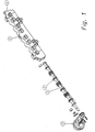
- FIG. 1 shows an exploded view of a device according to a variant of the present invention.
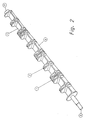
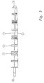
- Figures 2 and 3 show a detailed view of the plug of this device, respectively in perspective and in a section through a plane perpendicular to the shutter elements and passing through their axis of rotation.
- FIGS. 4 to 6 show this device in the open position, seen from the front (FIG. 4) and in section along the planes C1 (FIG. 5) and C8 (FIG. 6) in FIG. 4, the sections having been completed respectively at left, by a cut in the cylinder head, and to the right, by a section in a manifold to which the shutter device is advantageously integrated.
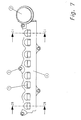
- FIGS. 7 to 9 represent this device in the closed position, respectively viewed from the front (FIG.
- Figure 1 shows a device according to the present invention comprising a plug provided with shutter elements (1) and connecting elements (2).
- This plug is actuable by means of a pneumatic actuator (3), and it is intended to be introduced into a sleeve (4) provided with fixing lugs (5).
- the sheath is provided with openings of the same size as the internal diameter of the tubes to be sealed, and which are aligned therewith.
- the illustrated device is intended to partially seal (on their lower part only) the intake manifolds of a 4-cylinder engine having two intake valves per cylinder. That is why it is provided with 4 times 2 openings.
- Figures 2 and 3 show the details of the bushel from different angles.
- the shutter elements comprise plates which are provided with ribs (6), and that the connecting elements are provided with recesses, some of which (7) are designed to contain anti-vibration elements (rings) as described. previously (not shown).
- one end of the axis of rotation (8) has a shape adapted to be coupled to the actuator (3), and that the other end of the axis of rotation (9) has a suitable shape to be supported by the sheath.
- Figure 3 shows that in accordance with the present invention, the axis of rotation, which passes through the center of the ends (8) and (9), passes through the longitudinal wall of at least one shutter member.
- the plug has a simple shape, balanced, free from unbalance, which is easy to mold in one piece, for example in plastic material.
- a bushel of this form has a moment of inertia in flexion and torsion high, which reduces mechanical stress and vibration problems in service.
- Figures 4 to 6 show that when the device is in the open position, the plates have their upper surface (which is substantially flat) aligned with the lower edge of the openings of the sleeve, the latter being aligned with the bottom wall of the conduits to be closed .
- the flow of air from the collector to the cylinder head is not disturbed.
- Figures 7 to 9 show that when the device is in the closed position, a wall (10) is necessary to obtain the closure of the lower part of the cylinder head ducts that it is desired to close.
- FIGs 4 to 9 also show, in an exaggerated manner, the advantageous variant according to which both the plug and the sheath are tapered.
- the plates and the recess in the plug are of larger size than in sections along the planes C8 (FIGS. 6 and 9).
Landscapes
- Engineering & Computer Science (AREA)
- Chemical & Material Sciences (AREA)
- Combustion & Propulsion (AREA)
- Mechanical Engineering (AREA)
- General Engineering & Computer Science (AREA)
- Characterised By The Charging Evacuation (AREA)
- Control Of Throttle Valves Provided In The Intake System Or In The Exhaust System (AREA)
- Motor Or Generator Cooling System (AREA)
- Lift Valve (AREA)
- Exhaust Gas After Treatment (AREA)
Description
- La présente invention concerne un dispositif d'obturation de conduits d'admission d'air d'un moteur à combustion interne multicylindre. Plus particulièrement, elle concerne un dispositif d'obturation permettant d'agir sur le débit gazeux circulant entre le collecteur d'admission du moteur (qui est formé d'une partie commune ou plenum et d'un répartiteur constitué de tubulures d'admission) et ses différents cylindres.
- Dans ce type de moteurs, on cherche à optimiser la combustion du carburant dans les cylindres en améliorant le mélange du combustible et de l'air utilisé comme comburant pendant la phase d'admission. Dans les moteurs à injection de carburant, le problème est crucial aux bas régimes de fonctionnement, étant donné l'absence de système à carburateur qui réalise un aérosol de carburant dans l'air d'admission. Le problème est généralement résolu en provoquant de la turbulence dans les débits gazeux qui sont introduits dans chaque cylindre du moteur. Une technique souvent utilisée est celle de l'effet "swirl" ou encore de la rotation des gaz dès leur entrée dans le cylindre afin de créer un mouvement tourbillonnaire d'axe parallèle à celui du cylindre, propice à l'amélioration du mélange air - carburant. Pour y parvenir, on peut par exemple, à bas régime, obturer une tubulure d'admission sur deux dans le cas des moteurs à deux tubulures d'admission par cylindre. Une autre technique consiste à générer un effet "tumble", c'est-à-dire un mouvement tourbillonnaire dont l'axe est perpendiculaire à celui du cylindre. Ce genre d'effet peut être obtenu en prévoyant un conduit culasse séparé en deux parties par une paroi et en obturant une des deux parties de ce conduit.
- Des dispositifs capables de générer un effet swirl ou un effet tumble d'intensité variable selon la charge et le régime du moteur, et qui ne perturbent pas l'écoulement de l'air à haut régime (c.à.d. en position ouverte) ont été mis au point. Ainsi, la demande de brevet EP 1 083 310 divulgue un système d'obturation pour moteurs comportant plus d'une soupape d'admission par cylindre qui est réalisé au moyen d'un double collecteur (un pour chaque série de tubulures d'admission) dont une partie (celle relative à une série de tubulures d'admission) est équipée d'un boîtier comprenant un boisseau permettant l'obturation des tubulures. Le boisseau est logé dans un alésage réalisé dans le boîtier et il comporte des éléments obturateurs d'une géométrie adaptée pour que en position ouverte, l'écoulement de l'air ne soit pas perturbé. Un tel boisseau présente toutefois l'inconvénient d'une géométrie compliquée et d'une rigidité faible, qui pourrait mener en service, à des problèmes de vibration. En outre, un système à double collecteur implique le montage d'une pièce supplémentaire, avec les frais de main d'oeuvre et les risques de défaut d'étanchéité associés. Enfin, le type de boisseau décrit dans cette demande ne permet pas l'obturation partielle des conduits d'admission sans perturber l'écoulement de l'air dans la partie non obturée
- Pour remédier à ces défauts, tout en gardant l'avantage d'un écoulement non perturbé en position ouverte, l'invention a pour but de fournir un dispositif d'obturation de géométrie simple, tout en étant rigide, et qui est apte à obturer entièrement ou partiellement des conduits d'admission. En outre, ce dispositif peut être intégré au répartiteur d'air et constituer ainsi une seule pièce d'équipement qui peut être montée en une seule opération par le constructeur du moteur sur la culasse de celui-ci.
- A cet effet, l'invention concerne un dispositif d'obturation de conduits d'admission d'air d'un moteur à combustion interne multicylindre, comprenant un boisseau muni de plusieurs éléments obturateurs ainsi qu'un fourreau muni de part et d'autre d'ouvertures latérales pour le passage de l'air et présentant un évidement longitudinal dans lequel le boisseau est inséré et peut tourner autour d'un axe de rotation, selon lequel les éléments obturateurs comportent une plaque ayant une surface fonctionnelle substantiellement plane qui, lorsque le dispositif est en position ouverte, est alignée avec le bord inférieur ou supérieur d'une ouverture correspondante du fourreau et selon lequel l'axe de rotation traverse la plaque d'au moins un élément obturateur.
- Le dispositif d'obturation selon la présente invention permet de fermer à volonté, totalement ou partiellement, au moins une partie des conduits d'admission d'air d'un moteur à combustion interne. Ces conduits sont les conduits présents dans chaque moteur thermique, aboutissant à la partie supérieure de chaque cylindre à l'endroit d'une soupape d'admission et provenant d'un répartiteur chargé de répartir l'air aspiré entre tous les cylindres.
- Par moteur thermique, on entend désigner ici un moteur à combustion interne ou à explosion comprenant au moins deux cylindres dans chacun desquels coulisse un piston animé d'un mouvement alternatif qui est transformé en mouvement de rotation au moyen d'un système bielle-manivelle et dans lequel l'énergie chimique de combustion d'un carburant est transformée en énergie cinétique de rotation d'un arbre.
- Le dispositif selon l'invention est généralement situé entre le répartiteur d'air et la culasse, c'est-à-dire entre la pièce qui répartit entre les différents cylindres l'air utilisé comme comburant par le moteur et la culasse de celui-ci.
- Selon l'invention, le fourreau comporte de part et d'autre des ouvertures latérales pour le passage de l'air, ainsi qu'un évidement longitudinal pour y loger le boisseau et permettre son mouvement de rotation autour d'un axe. Les ouvertures latérales peuvent être de forme quelconque. Cette forme est généralement adaptée, et le plus souvent identique à la forme des conduits à obturer. De préférence, la forme du conduit à obturer est substantiellement rectangulaire. Toutefois, quelle que soit leur forme, ces conduits présentent avantageusement une découpe dans les coins.
- Selon l'invention, les éléments obturateurs comportent une plaque ayant une surface fonctionnelle substantiellement plane qui s'aligne avec le bord inférieur ou le bord supérieur d'une ouverture correspondante du fourreau lorsque le dispositif est en position ouverte, et ce selon que l'on désire obturer les conduits à partir du haut ou du bas (ou seulement la portion inférieure ou supérieure de ceux-ci).. Par « substantiellement plane», on entend qu'au moins 80% de la surface, de préférence au moins 90%, voire au moins 95% de la surface est plane. Il s'agit généralement de la portion centrale de la surface, les bords pouvant être munis d'une découpe en vue de_perturber le moins possible l'écoulement. La forme et la taille de ces éléments, ainsi que l'emplacement de leur axe de rotation par rapport aux tubulures à obturer, sont adaptés à la forme et à la taille des tubulures à obturer, ainsi qu'à la forme interne du fourreau.
- Afin d'obtenir un boisseau d'une rigidité suffisante pour résister aux efforts mécaniques en service et aux vibrations sans devoir augmenter exagérément l'épaisseur des plaques, il est souvent avantageux de munir celles-ci d'une ou de plusieurs nervures du côté opposé à la surface fonctionnelle. Le nombre, la géométrie et la disposition de ces nervures sont adaptés de manière à augmenter au maximum le moment d'inertie en flexion et en torsion de la pièce. De préférence, toutes les plaques sont munies de nervures identiques. Ces nervures sont généralement perpendiculaires à celles-ci. Elles sont souvent comprises dans un plan qui englobe l'axe de rotation. Une seule nervure centrale suffit généralement à obtenir une rigidité en flexion et torsion satisfaisante. La hauteur de cette nervure sera adaptée en fonction de la rigidité désirée, et de l'emplacement disponible dans le boîtier. Dans le cas où les tubulures à obturer sont cylindriques, cette nervure aura de préférence une hauteur substantiellement égale au rayon du conduit à obturer.
- Selon l'invention, le dispositif permet l'obturation de plusieurs conduits d'admission d'air et la commande de fermeture est simultanée pour tous les conduits. De préférence, le taux d'obturation réalisé est identique pour chaque conduit correspondant pour chaque cylindre.
- Le dispositif selon la présente invention peut être une pièce séparée que l'on vient intercaler entre le collecteur et la culasse du moteur.
- Alternativement, et de manière préférée, le dispositif selon la présente invention est intégré au collecteur d'admission. A noter que dans ce cas, si l'architecture le permet, le collecteur peut également intégrer un couvre-culasse, ce qui permet de réduire au maximum le nombre de pièces à monter sur le moteur. De préférence, le fourreau est moulé d'une seule pièce avec le collecteur d'admission.
- Afin de maintenir le boisseau en place dans le fourreau tout en permettant sa rotation, ledit boisseau est généralement muni en ses deux extrémités de tourillons de guidage. A une extrémité, le tourillon est relié à une organe d'entraînement actionné par un dispositif adéquat, et à l'autre extrémité, le tourillon est inséré dans un logement qui est soit intégré au fourreau, soit réalisé dans une pièce séparée faisant office de bouchon. Pour diminuer les frottements lors de la rotation du tourillon dans le logement, au moins une de ces pièces (tourillon et/ou logement) peut être constituée au moins en surface, d'un matériau à faible coefficient de frottement. Alternativement, une pièce supplémentaire en un tel matériau peut être insérée entre le tourillon et le logement. Si nécessaire, l'étanchéité vers l'extérieur est améliorée au moyen de joints (de type o-ring ou joints à lèvres par exemple).
- Dans le dispositif selon la présente invention, le boisseau peut être entraîné dans son mouvement de rotation autour de son axe par tout moyen connu. Ainsi par exemple, l'axe peut être muni en son bout d'un actionneur pneumatique. En outre, la position angulaire du boisseau peut être mesurée à l'aide de tout dispositif connu, par exemple au moyen d'un potentiomètre.
- Les éléments obturateurs peuvent être réalisés en différentes matières ou compositions compatibles avec l'environnement du moteur et en particulier, celui des conduits d'admission d'air. On peut par exemple utiliser des éléments en métal. On peut ainsi utiliser des volets en acier ou en alliage d'aluminium. On peut encore utiliser des éléments obturateurs en matière plastique, par exemple un boisseau à base de résine thermoplastique ou thermodurcissable. Les éléments obturateurs réalisés en matière plastique sont préférés.
- Les éléments obturateurs sont reliés entre eux par des éléments de liaison de section circulaire dont l'axe de symétrie coïncide avec l'axe de rotation du boisseau et dont le diamètre extérieur est réalisé à des dimensions et avec une tolérance permettant la rotation du boisseau dans le fourreau. A noter que cette même exigence de dimensions et tolérance existe pour le contour des éléments obturateurs. Selon une variante préférée de la présente invention, ces éléments de liaison sont pourvus d'évidements afin de réduire le poids du boisseau. Avantageusement, ces évidements ont la forme de portions de disques dans un plan perpendiculaire à l'axe de rotation du boisseau.
- De manière avantageuse, au moins un de ces éléments de liaison est pourvu d'une bague. Cet élément, dont la fonction est de réduire les bruits produits par les vibrations, est réalisé à partir d'un matériau à faible coefficient de frottement tel que le POM (ou polyoxyméthylène). Selon une variante, la ou les bagues sont constituées de plusieurs pièces assemblées par clippage sur les évidements des éléments de liaison. Dans ce cas, les bagues présentent un diamètre extérieur légèrement supérieur à celui des éléments de liaison. Selon une autre variante, la ou les bagues sont montées à l'intérieur du fourreau, au droit des éléments de liaison.
- Les éléments de liaison peuvent être, indépendamment de la nature des éléments obturateurs qu'ils relient, réalisés en des matières ou compositions de natures diverses. Ils peuvent, par exemple être réalisés en métal, comme par exemple en acier ou en métal léger tel que l'aluminium ou un alliage d'aluminium. Ils peuvent aussi avantageusement être réalisé en matière plastique. Comme matière plastique, on peut par exemple utiliser une résine polyamide.
- Selon une variante particulièrement préférée de la présente invention, le boisseau (c.à.d . l'assemblage des éléments obturateurs et des éléments de liaison) est réalisé d'une seule pièce, et de préférence par moulage. A cet effet, une matière plastique telle que le polyamide, éventuellement chargée avec une ou des matières particulaires (talc ou billes de verre par exemple) ou fibreuses (fibres de verre ou de carbone par exemple), convient bien. Cette matière plastique peut comprendre un additif permettant de réduire son coefficient de friction (PTFE par exemple) mais pas en des quantités susceptibles de nuire à sa résistance mécanique.
- Le dispositif décrit plus haut est particulièrement bien adapté à l'utilisation dans un moteur comprenant plus d'une soupape d'admission par cylindre, et en particulier, aux moteurs ayant deux soupapes d'admission par cylindre et donc également, deux conduits d'admission par cylindre. Les éléments obturateurs peuvent ainsi être conçus et disposés de manière à pouvoir obturer soit entièrement un conduit sur deux, soit partiellement chacun des conduits. Dans le cas d'une obturation partielle des conduits, les conduits d'admission de la culasse sont munis d'une paroi qui les partage en deux parties dont seulement une sera obturée par le dispositif selon la présente invention vient obturer. Dans ce cas, le dispositif selon la présente invention permet, par un dimensionnement adéquat, de ne pas perturber l'écoulement de la partie que l'on ne désire pas obturer, même en position fermée.
- Lorsque le dispositif selon la présente invention est destiné à obturer seulement partiellement les conduits d'admission d'air, il est généralement pourvu d'une paroi moulée d'une pièce avec le fourreau et qui prolonge en général une paroi similaire apposée dans les conduits d'admission de la culasse. En effet, le boisseau étant animé d'un mouvement de rotation autour de son axe et la position fermée impliquant un angle non nul des éléments obturateurs par rapport à la paroi inférieure de la tubulure, cette paroi est nécessaire pour effectivement obtenir l'obturation de la partie du conduit visée. Ainsi, selon cette variante de l'invention, le fourreau comprend une paroi interne contre laquelle les éléments obturateurs viennent s'ajuster en position fermée. Dans ce cas, le profil des bords de cette paroi et de l'élément obturateur sont conçus de manière à obtenir un débit de fuite limité et identique pour chaque conduit lorsque le dispositif est en position fermée. A cette fin, on prévoit avantageusement un jeu de 0.1 à 5 mm entre les plaques et les parois dans chaque conduit obturé, une valeur d'environ 0.5 mm convenant bien. De manière préférée, la paroi est perpendiculaire aux ouvertures latérales dans le fourreau.
- Le dispositif selon la présente invention convient particulièrement pour obturer partiellement les conduits d'un moteur que l'on désire alimenter de façon totalement séparée en air frais et en gaz d'échappement recyclés.
- Lorsque le fourreau du dispositif selon la présente invention est réalisé par moulage en matière plastique, un élément important à prendre en compte est l'obtention de l'évidement longitudinal en son sein. En effet, on utilise généralement un noyau à cette fin, qu'il importe de pouvoir ôter lors du démoulage. Une technique simple, mais coûteuse, est de recourir à un noyau fusible (par exemple à base d'un métal ou d'un alliage à bas point de fusion, tel qu'il est connu de l'homme de l'art). Une autre technique consiste à prévoir un évidement conique. Afin d'obtenir une pièce aisément démoulable, l'angle de la conicité est avantageusement compris entre 0.1 et 1 °. En outre, afin d'obtenir une bonne étanchéité avec le boisseau, on veillera à ce que le boisseau soit également conique, l'axe des deux cônes correspondant avec l'axe de rotation du boisseau lorsque celui-ci est inséré dans le fourreau.
- Dans le cas d'un boisseau conique et de l'obturation, partielle des conduits, on veillera à adapter la disposition de l'axe du cône (et donc, de l'axe de rotation) de manière à ce que la longueur de l'écoulement dans la partie de non obturée de ceux-ci soit contante d'un conduit à l'autre, et ce pour des raisons d'homogénéité de remplissage principalement. Dans ce cas donc, la longueur de la paroi d'ajustage (dans une direction perpendiculaire à l'axe de rotation) sera la même dans chaque conduit. Alternativement, la longueur de cette paroi peut être variable d'un conduit à l'autre tout le long du fourreau. Dans ce cas toutefois, la longueur de l'écoulement dans la partie non obturée ne sera pas la même d'un conduit à l'autre, ce qui peut mener à des problèmes de remplissage du moteur.
- La présente invention est illustrée de manière non limitative par les figures 1 à 9.
- La figure 1 représente une vue éclatée d'un dispositif selon une variante de la présente invention.
Les figures 2 et 3 représentent une vue détaillée du boisseau de ce dispositif, respectivement en perpective et selon une coupe par un plan perpendiculaire aux éléments obturateurs et passant par leur axe de rotation.
Les figures 4 à 6 représentent ce dispositif en position ouverte, respectivement vu de face (figure 4) et en coupe selon les plans marqués C1 (figure 5) et C8 (figure 6) dans la figure 4, les coupes ayant été complétées respectivement à gauche, par une coupe dans la culasse, et à droite, par une coupe dans un collecteur auquel le dispositif obturateur est avantageusement intégré.
Les figures 7 à 9 représentent ce dispositif en position fermée, respectivement vu de face (figure 7) et en coupe selon les plans marqués C1 (figure 8) et C8 (figure 9) dans la figure 7, les coupes ayant été complétées respectivement à gauche, par une coupe dans la culasse, et à droite, par une coupe dans un collecteur auquel le dispositif obturateur est avantageusement intégré. - Dans toutes ces figures, on a utilisé des numéros identiques pour désigner des pièces ou parties de pièces identiques.
- Ainsi, la figure 1 montre un dispositif selon la présente invention comprenant un boisseau muni d'éléments obturateurs (1) et d'éléments de liaison (2). Ce boisseau est actionnable au moyen d'un actionneur pneumatique (3), et il est destiné à être introduit dans un fourreau (4) muni de pattes de fixation (5). Le fourreau est muni d'ouvertures de même taille que le diamètre interne des tubulures à obturer, et qui sont alignées avec celles-ci. Le dispositif illustré est destiné à obturer partiellement (sur leur partie inférieure uniquement) les tubulures d'admission d'un moteur à 4 cylindres ayant deux soupapes d'admission par cylindre. C'est pourquoi il est muni de 4 fois 2 ouvertures.
- Les figures 2 et 3 montrent les détails du boisseau sous différents angles. On voit ainsi que les éléments obturateurs comprennent des plaques qui sont munies de nervures (6), et que les éléments de liaison sont munis d'évidements dont certains (7) sont prévus pour contenir des éléments anti-vibrations (bagues) tels que décrits précédemment (non représentés). On voit également qu'une extrémité de l'axe de rotation (8) présente une forme adaptée pour être accouplée à l'actionneur (3), et que l'autre extrémité de l'axe de rotation (9) présente une forme adaptée pour être supportée par le fourreau . La figure 3 montre bien que conformément à la présente invention, l'axe de rotation, qui passe par le centre des extrémités (8) et (9), traverse la paroi longitudinale d'au moins un élément obturateur. L'avantage est qu'avec de tels éléments obturateurs, qui sont substantiellement centrés sur l'axe de rotation, le boisseau présente une forme simple, équilibrée, exempte de balourds, qui est facile à mouler d'une seule pièce, par exemple en matière plastique. En outre, un boisseau de cette forme présente un moment d'inertie en flexion et en torsion élevé, ce qui permet de réduire les sollicitations mécaniques et les problèmes de vibrations en service.
- Les figures 4 à 6 montrent que lorsque le dispositif est en position ouverte, les plaques ont leur surface supérieure (qui est substantiellement plane) alignée avec le bord inférieur des ouvertures du fourreau, celui-ci étant aligné avec la paroi inférieure des conduits à obturer. Ainsi, l'écoulement de l'air du collecteur vers la culasse (de droite à gauche sur les figures 5 et 6) n'est pas perturbé.
- Les figures 7 à 9 montrent que lorsque le dispositif est en position fermée, une paroi (10) est nécessaire pour obtenir l'obturation de la partie inférieure des conduits culasse que l'on désire obturer.
- Les figures 4 à 9 montrent également, de manière exagérée, la variante avantageuse selon laquelle à la fois le boisseau et le fourreau sont coniques. En effet, il apparaît clairement que dans les coupes selon les plans C1 (figures 5 et 8), les plaques et l'évidement dans le boisseau sont de plus grande dimension que dans coupes selon les plans C8 (figures 6 et 9).
Claims (10)
- Dispositif d'obturation de conduits d'admission d'air d'un moteur à combustion interne multicylindre, comprenant un boisseau muni de plusieurs éléments obturateurs (1) ainsi qu'un fourreau (4) muni de part et d'autre d'ouvertures latérales pour le passage de l'air et présentant un évidement longitudinal dans lequel le boisseau est inséré et peut tourner autour d'un axe de rotation, selon lequel les éléments obturateurs (1) comportent une plaque ayant une surface fonctionnelle substantiellement plane qui, lorsque le dispositif est en position ouverte, est alignée avec le bord inférieur ou supérieur d'une ouverture correspondante du fourreau et selon lequel l'axe de rotation traverse la plaque d'au moins un élément obturateur.
- Dispositif selon la revendication 1, dans lequel les plaques des éléments obturateurs sont munies du côté opposé à la surface fonctionnelle d'une ou de plusieurs nervures (6).
- Dispositif selon l'une quelconque des revendications précédentes, dans lequel les parois longitudinales comprennent une nervure centrale (6) perpendiculaire à celles-ci et située dans un plan qui englobe l'axe de rotation.
- Dispositif selon l'une quelconque des revendications précédentes, dans lequel le fourreau (4) est intégré à un collecteur d'admission.
- Dispositif selon l'une quelconque des revendications précédentes, dans lequel le boisseau comprend des éléments de liaison (2) de section circulaire qui relient les éléments obturateurs (1) entre eux, dont l'axe de symétrie coïncide avec l'axe de rotation, et qui sont munis d'évidements.
- Dispositif selon la revendication 5, dans lequel au moins un évidement (7) est pourvu d'une bague en matériau à faible coefficient de friction.
- Dispositif selon l'une quelconque des revendications précédentes, dans lequel le boisseau est réalisé d'une seule pièce en matière plastique.
- Dispositif selon l'une quelconque des revendications précédentes, dans lequel le fourreau comprend une paroi interne (10) contre laquelle les éléments obturateurs viennent s'ajuster en position fermée du dispositif.
- Dispositif selon la revendication 8, dans lequel le boisseau est conique et son axe de rotation est disposé de manière à obtenir un jeu constant entre les éléments obturateurs (1) et la paroi (10) contre laquelle ils viennent buter pour obturer les (parties de) conduits d'admissions.
- Utilisation d'un dispositif selon la revendication précédente, dans un moteur ayant deux soupapes d'admission par cylindre.
Applications Claiming Priority (3)
| Application Number | Priority Date | Filing Date | Title |
|---|---|---|---|
| FR0106050 | 2001-05-02 | ||
| FR0106050A FR2824360B1 (fr) | 2001-05-02 | 2001-05-02 | Dispositif d'obturation de conduits d'admission d'air d'un moteur |
| PCT/EP2002/004675 WO2002088533A1 (fr) | 2001-05-02 | 2002-04-26 | Dispositif d'obturation de conduits d'admission d'air d'un moteur |
Publications (2)
| Publication Number | Publication Date |
|---|---|
| EP1383996A1 EP1383996A1 (fr) | 2004-01-28 |
| EP1383996B1 true EP1383996B1 (fr) | 2006-08-16 |
Family
ID=8863029
Family Applications (1)
| Application Number | Title | Priority Date | Filing Date |
|---|---|---|---|
| EP02735311A Expired - Lifetime EP1383996B1 (fr) | 2001-05-02 | 2002-04-26 | Dispositif d'obturation de conduits d'admission d'air d'un moteur |
Country Status (6)
| Country | Link |
|---|---|
| EP (1) | EP1383996B1 (fr) |
| JP (1) | JP2004526098A (fr) |
| AT (1) | ATE336646T1 (fr) |
| DE (1) | DE60213963D1 (fr) |
| FR (1) | FR2824360B1 (fr) |
| WO (1) | WO2002088533A1 (fr) |
Families Citing this family (9)
| Publication number | Priority date | Publication date | Assignee | Title |
|---|---|---|---|---|
| US6622696B2 (en) * | 2002-02-04 | 2003-09-23 | Delphi Technologies, Inc. | Throttle valve having a large diameter shaft with integral valve plate |
| DE102004045730B3 (de) * | 2004-09-21 | 2006-03-16 | Pierburg Gmbh | Klappenvorrichtung für ein Luftansaugkanalsystem einer Verbrennungskraftmaschine |
| US7213547B2 (en) | 2004-12-14 | 2007-05-08 | Massachusetts Institute Of Technology | Valve |
| JP2007170279A (ja) * | 2005-12-22 | 2007-07-05 | Aisin Seiki Co Ltd | 内燃機関の吸気装置 |
| JP4623206B2 (ja) | 2008-11-20 | 2011-02-02 | 株式会社デンソー | 内燃機関の吸気装置 |
| FR2957121A1 (fr) * | 2010-03-02 | 2011-09-09 | Mann & Hummel Gmbh | Dispositif d'admission d'air pour moteur a combustion interne |
| DE102011102445A1 (de) * | 2011-05-25 | 2012-11-29 | GM Global Technology Operations LLC (n. d. Gesetzen des Staates Delaware) | Lufteinlassvorrichtung |
| JP5842737B2 (ja) * | 2012-06-11 | 2016-01-13 | アイシン精機株式会社 | 吸気制御装置 |
| EP2772623B1 (fr) * | 2013-02-28 | 2017-08-23 | MAHLE Filter Systems Japan Corporation | Système d'entrée d'air pour moteur à combustion interne |
Family Cites Families (5)
| Publication number | Priority date | Publication date | Assignee | Title |
|---|---|---|---|---|
| DE59107147D1 (de) * | 1990-10-11 | 1996-02-08 | Wolfram Willeke | Brennkraftmaschine mit einem zylindrischen Schieber |
| US5487365A (en) * | 1991-02-21 | 1996-01-30 | Yamaha Hatsudoki Kabushiki Kaisha | Induction system for engine |
| EP0529676B1 (fr) * | 1991-08-30 | 1995-12-13 | Yamaha Hatsudoki Kabushiki Kaisha | Système d'admission pour un moteur à combustion interne |
| FR2774125B1 (fr) * | 1998-01-29 | 2000-03-31 | Peugeot | Dispositif de commande d'ouverture et de fermeture d'au moins un conduit d'air d'une culasse d'un moteur a combustion interne |
| FR2798426B1 (fr) | 1999-09-10 | 2002-09-13 | Renault | Dispositif d'admission variable pour moteur thermique et boisseau pour un tel dispositif |
-
2001
- 2001-05-02 FR FR0106050A patent/FR2824360B1/fr not_active Expired - Fee Related
-
2002
- 2002-04-26 AT AT02735311T patent/ATE336646T1/de not_active IP Right Cessation
- 2002-04-26 DE DE60213963T patent/DE60213963D1/de not_active Expired - Lifetime
- 2002-04-26 EP EP02735311A patent/EP1383996B1/fr not_active Expired - Lifetime
- 2002-04-26 JP JP2002585799A patent/JP2004526098A/ja active Pending
- 2002-04-26 WO PCT/EP2002/004675 patent/WO2002088533A1/fr not_active Ceased
Also Published As
| Publication number | Publication date |
|---|---|
| FR2824360A1 (fr) | 2002-11-08 |
| FR2824360B1 (fr) | 2003-09-12 |
| WO2002088533A1 (fr) | 2002-11-07 |
| ATE336646T1 (de) | 2006-09-15 |
| JP2004526098A (ja) | 2004-08-26 |
| DE60213963D1 (de) | 2006-09-28 |
| EP1383996A1 (fr) | 2004-01-28 |
Similar Documents
| Publication | Publication Date | Title |
|---|---|---|
| EP0701057B1 (fr) | Tubulure d'admission d'air à volets pivotants pour moteur à combustion interne | |
| EP1269007B1 (fr) | Collecteur d'admission d'air a elargissement brusque, pour moteur a combustion interne s exterieurs et pour la difusion de telles sequences | |
| EP1383996A1 (fr) | Dispositif d'obturation de conduits d'admission d'air d'un moteur | |
| FR3070633A1 (fr) | Volet d'obturation pour dispositif de regulation d'un flux d'air pour module de face avant pour vehicule automobile | |
| FR2746446A1 (fr) | Collecteur d'admission d'air, a element escamotable a conduit acoustique, pour moteurs a combustion interne | |
| FR2923886A1 (fr) | Vanne pour circuit d'alimentation en air d'un moteur de vehicule automobile, circuit comportant une telle vanne et procede de commande d'un moteur utilisant un tel circuit | |
| EP1328714B1 (fr) | Dispositif d'obturation de conduits d'admission d'air d'un moteur | |
| EP0625631A1 (fr) | Boisseau rotatif amélioré | |
| EP0577451A1 (fr) | Dispositif de contrôle de l'injection pneumatique d'un mélange carburé dans un moteur à combustion interne à deux temps et utilisation associée | |
| FR2642795A1 (fr) | Dispositif d'admission pour moteur a combustion interne | |
| EP1132667B1 (fr) | Système de réduction de section d'écoulement pour canalisation de fluide | |
| EP1188912A1 (fr) | Dispositif d'admission d'air dans un cylindre de moteur à combustion | |
| EP2850299A1 (fr) | Vanne de circulation de fluide, notamment pour vehicule automobile, et dispositif de conditionnement thermique comprenant une telle vanne | |
| FR2682431A1 (fr) | Collecteur d'admission pour moteur thermique. | |
| EP2850349B1 (fr) | Vanne de circulation de fluide | |
| FR2919682A1 (fr) | Repartiteur d'admission d'un moteur a combustion interne | |
| EP1247957A1 (fr) | Dispositif d'admission d'air dans un cylindre de moteur à combustion | |
| FR2914978A1 (fr) | Vanne quatre voies a obturation simultanee de deux voies | |
| EP3997326B1 (fr) | Répartiteur d'air pour moteurs à combustion thermique | |
| FR2957121A1 (fr) | Dispositif d'admission d'air pour moteur a combustion interne | |
| FR2910065A1 (fr) | Culasse comprenant des conduits d'admission pourvus d'anneaux generateurs de tourbillons. | |
| FR2739897A1 (fr) | Diffuseur annulaire de recyclage de gaz carbures, pour moteur a combustion interne | |
| FR2822499A1 (fr) | Agencement de carburateur | |
| FR2842463A1 (fr) | Aerateur pour vehicule automobile a debit d'air reglable et flux orientable, et vehicule equipe d'un tel aerateur | |
| FR2764940A1 (fr) | Dispositif d'obturation de conduits d'admission d'un moteur a explosion |
Legal Events
| Date | Code | Title | Description |
|---|---|---|---|
| PUAI | Public reference made under article 153(3) epc to a published international application that has entered the european phase |
Free format text: ORIGINAL CODE: 0009012 |
|
| 17P | Request for examination filed |
Effective date: 20031013 |
|
| AK | Designated contracting states |
Kind code of ref document: A1 Designated state(s): AT BE CH CY DE DK ES FI FR GB GR IE IT LI LU MC NL PT SE TR |
|
| AX | Request for extension of the european patent |
Extension state: AL LT LV MK RO SI |
|
| GRAP | Despatch of communication of intention to grant a patent |
Free format text: ORIGINAL CODE: EPIDOSNIGR1 |
|
| GRAS | Grant fee paid |
Free format text: ORIGINAL CODE: EPIDOSNIGR3 |
|
| GRAA | (expected) grant |
Free format text: ORIGINAL CODE: 0009210 |
|
| RAP1 | Party data changed (applicant data changed or rights of an application transferred) |
Owner name: MANN+HUMMEL GMBH |
|
| AK | Designated contracting states |
Kind code of ref document: B1 Designated state(s): AT BE CH CY DE DK ES FI FR GB GR IE IT LI LU MC NL PT SE TR |
|
| PG25 | Lapsed in a contracting state [announced via postgrant information from national office to epo] |
Ref country code: IT Free format text: LAPSE BECAUSE OF FAILURE TO SUBMIT A TRANSLATION OF THE DESCRIPTION OR TO PAY THE FEE WITHIN THE PRESCRIBED TIME-LIMIT;WARNING: LAPSES OF ITALIAN PATENTS WITH EFFECTIVE DATE BEFORE 2007 MAY HAVE OCCURRED AT ANY TIME BEFORE 2007. THE CORRECT EFFECTIVE DATE MAY BE DIFFERENT FROM THE ONE RECORDED. Effective date: 20060816 Ref country code: NL Free format text: LAPSE BECAUSE OF FAILURE TO SUBMIT A TRANSLATION OF THE DESCRIPTION OR TO PAY THE FEE WITHIN THE PRESCRIBED TIME-LIMIT Effective date: 20060816 Ref country code: IE Free format text: LAPSE BECAUSE OF FAILURE TO SUBMIT A TRANSLATION OF THE DESCRIPTION OR TO PAY THE FEE WITHIN THE PRESCRIBED TIME-LIMIT Effective date: 20060816 Ref country code: AT Free format text: LAPSE BECAUSE OF FAILURE TO SUBMIT A TRANSLATION OF THE DESCRIPTION OR TO PAY THE FEE WITHIN THE PRESCRIBED TIME-LIMIT Effective date: 20060816 Ref country code: FI Free format text: LAPSE BECAUSE OF FAILURE TO SUBMIT A TRANSLATION OF THE DESCRIPTION OR TO PAY THE FEE WITHIN THE PRESCRIBED TIME-LIMIT Effective date: 20060816 |
|
| REG | Reference to a national code |
Ref country code: GB Ref legal event code: FG4D Free format text: NOT ENGLISH |
|
| REG | Reference to a national code |
Ref country code: CH Ref legal event code: EP |
|
| REG | Reference to a national code |
Ref country code: IE Ref legal event code: FG4D Free format text: LANGUAGE OF EP DOCUMENT: FRENCH |
|
| REF | Corresponds to: |
Ref document number: 60213963 Country of ref document: DE Date of ref document: 20060928 Kind code of ref document: P |
|
| GBT | Gb: translation of ep patent filed (gb section 77(6)(a)/1977) |
Effective date: 20061018 |
|
| PG25 | Lapsed in a contracting state [announced via postgrant information from national office to epo] |
Ref country code: DK Free format text: LAPSE BECAUSE OF FAILURE TO SUBMIT A TRANSLATION OF THE DESCRIPTION OR TO PAY THE FEE WITHIN THE PRESCRIBED TIME-LIMIT Effective date: 20061116 Ref country code: SE Free format text: LAPSE BECAUSE OF FAILURE TO SUBMIT A TRANSLATION OF THE DESCRIPTION OR TO PAY THE FEE WITHIN THE PRESCRIBED TIME-LIMIT Effective date: 20061116 |
|
| PG25 | Lapsed in a contracting state [announced via postgrant information from national office to epo] |
Ref country code: DE Free format text: LAPSE BECAUSE OF FAILURE TO SUBMIT A TRANSLATION OF THE DESCRIPTION OR TO PAY THE FEE WITHIN THE PRESCRIBED TIME-LIMIT Effective date: 20061117 |
|
| PG25 | Lapsed in a contracting state [announced via postgrant information from national office to epo] |
Ref country code: ES Free format text: LAPSE BECAUSE OF FAILURE TO SUBMIT A TRANSLATION OF THE DESCRIPTION OR TO PAY THE FEE WITHIN THE PRESCRIBED TIME-LIMIT Effective date: 20061127 |
|
| PG25 | Lapsed in a contracting state [announced via postgrant information from national office to epo] |
Ref country code: PT Free format text: LAPSE BECAUSE OF FAILURE TO SUBMIT A TRANSLATION OF THE DESCRIPTION OR TO PAY THE FEE WITHIN THE PRESCRIBED TIME-LIMIT Effective date: 20070116 |
|
| NLV1 | Nl: lapsed or annulled due to failure to fulfill the requirements of art. 29p and 29m of the patents act | ||
| REG | Reference to a national code |
Ref country code: IE Ref legal event code: FD4D |
|
| PLBE | No opposition filed within time limit |
Free format text: ORIGINAL CODE: 0009261 |
|
| STAA | Information on the status of an ep patent application or granted ep patent |
Free format text: STATUS: NO OPPOSITION FILED WITHIN TIME LIMIT |
|
| 26N | No opposition filed |
Effective date: 20070518 |
|
| PGFP | Annual fee paid to national office [announced via postgrant information from national office to epo] |
Ref country code: GB Payment date: 20070426 Year of fee payment: 6 |
|
| REG | Reference to a national code |
Ref country code: CH Ref legal event code: PL |
|
| BERE | Be: lapsed |
Owner name: MANN+HUMMEL G.M.B.H. Effective date: 20070430 |
|
| PG25 | Lapsed in a contracting state [announced via postgrant information from national office to epo] |
Ref country code: CH Free format text: LAPSE BECAUSE OF NON-PAYMENT OF DUE FEES Effective date: 20070430 Ref country code: LI Free format text: LAPSE BECAUSE OF NON-PAYMENT OF DUE FEES Effective date: 20070430 |
|
| PG25 | Lapsed in a contracting state [announced via postgrant information from national office to epo] |
Ref country code: BE Free format text: LAPSE BECAUSE OF NON-PAYMENT OF DUE FEES Effective date: 20070430 |
|
| PG25 | Lapsed in a contracting state [announced via postgrant information from national office to epo] |
Ref country code: GR Free format text: LAPSE BECAUSE OF FAILURE TO SUBMIT A TRANSLATION OF THE DESCRIPTION OR TO PAY THE FEE WITHIN THE PRESCRIBED TIME-LIMIT Effective date: 20061117 |
|
| PGFP | Annual fee paid to national office [announced via postgrant information from national office to epo] |
Ref country code: FR Payment date: 20070416 Year of fee payment: 6 |
|
| GBPC | Gb: european patent ceased through non-payment of renewal fee |
Effective date: 20080426 |
|
| REG | Reference to a national code |
Ref country code: FR Ref legal event code: ST Effective date: 20081231 |
|
| PG25 | Lapsed in a contracting state [announced via postgrant information from national office to epo] |
Ref country code: MC Free format text: LAPSE BECAUSE OF NON-PAYMENT OF DUE FEES Effective date: 20070430 |
|
| PG25 | Lapsed in a contracting state [announced via postgrant information from national office to epo] |
Ref country code: FR Free format text: LAPSE BECAUSE OF NON-PAYMENT OF DUE FEES Effective date: 20080430 |
|
| PG25 | Lapsed in a contracting state [announced via postgrant information from national office to epo] |
Ref country code: GB Free format text: LAPSE BECAUSE OF NON-PAYMENT OF DUE FEES Effective date: 20080426 |
|
| PG25 | Lapsed in a contracting state [announced via postgrant information from national office to epo] |
Ref country code: LU Free format text: LAPSE BECAUSE OF NON-PAYMENT OF DUE FEES Effective date: 20070426 Ref country code: CY Free format text: LAPSE BECAUSE OF FAILURE TO SUBMIT A TRANSLATION OF THE DESCRIPTION OR TO PAY THE FEE WITHIN THE PRESCRIBED TIME-LIMIT Effective date: 20060816 |
|
| PG25 | Lapsed in a contracting state [announced via postgrant information from national office to epo] |
Ref country code: TR Free format text: LAPSE BECAUSE OF FAILURE TO SUBMIT A TRANSLATION OF THE DESCRIPTION OR TO PAY THE FEE WITHIN THE PRESCRIBED TIME-LIMIT Effective date: 20060816 |