EP1383994B1 - Modified otto engine with one cylinder - Google Patents
Modified otto engine with one cylinder Download PDFInfo
- Publication number
- EP1383994B1 EP1383994B1 EP02703025A EP02703025A EP1383994B1 EP 1383994 B1 EP1383994 B1 EP 1383994B1 EP 02703025 A EP02703025 A EP 02703025A EP 02703025 A EP02703025 A EP 02703025A EP 1383994 B1 EP1383994 B1 EP 1383994B1
- Authority
- EP
- European Patent Office
- Prior art keywords
- engine
- cylinder
- cylinder head
- fuel
- fuel nozzle
- Prior art date
- Legal status (The legal status is an assumption and is not a legal conclusion. Google has not performed a legal analysis and makes no representation as to the accuracy of the status listed.)
- Expired - Lifetime
Links
- 239000000446 fuel Substances 0.000 claims abstract description 39
- LFQSCWFLJHTTHZ-UHFFFAOYSA-N Ethanol Chemical compound CCO LFQSCWFLJHTTHZ-UHFFFAOYSA-N 0.000 claims abstract description 30
- 238000000034 method Methods 0.000 claims description 10
- 238000003754 machining Methods 0.000 claims description 3
- 238000005259 measurement Methods 0.000 claims description 3
- 238000012360 testing method Methods 0.000 description 17
- 230000007613 environmental effect Effects 0.000 description 13
- CURLTUGMZLYLDI-UHFFFAOYSA-N Carbon dioxide Chemical compound O=C=O CURLTUGMZLYLDI-UHFFFAOYSA-N 0.000 description 11
- 229910002092 carbon dioxide Inorganic materials 0.000 description 7
- 238000012986 modification Methods 0.000 description 6
- 230000004048 modification Effects 0.000 description 6
- 239000003380 propellant Substances 0.000 description 6
- 229910002091 carbon monoxide Inorganic materials 0.000 description 5
- 239000000243 solution Substances 0.000 description 5
- 239000004215 Carbon black (E152) Substances 0.000 description 3
- UGFAIRIUMAVXCW-UHFFFAOYSA-N Carbon monoxide Chemical compound [O+]#[C-] UGFAIRIUMAVXCW-UHFFFAOYSA-N 0.000 description 3
- 241000183024 Populus tremula Species 0.000 description 3
- QVGXLLKOCUKJST-UHFFFAOYSA-N atomic oxygen Chemical compound [O] QVGXLLKOCUKJST-UHFFFAOYSA-N 0.000 description 3
- 239000001569 carbon dioxide Substances 0.000 description 3
- 238000002485 combustion reaction Methods 0.000 description 3
- 230000006835 compression Effects 0.000 description 3
- 238000007906 compression Methods 0.000 description 3
- 229930195733 hydrocarbon Natural products 0.000 description 3
- 150000002430 hydrocarbons Chemical class 0.000 description 3
- 229910052760 oxygen Inorganic materials 0.000 description 3
- 239000001301 oxygen Substances 0.000 description 3
- 238000011161 development Methods 0.000 description 2
- 239000002551 biofuel Substances 0.000 description 1
- 230000000052 comparative effect Effects 0.000 description 1
- 238000001816 cooling Methods 0.000 description 1
- 238000013461 design Methods 0.000 description 1
- 238000003912 environmental pollution Methods 0.000 description 1
- 238000000227 grinding Methods 0.000 description 1
- 238000002347 injection Methods 0.000 description 1
- 239000007924 injection Substances 0.000 description 1
- 238000002372 labelling Methods 0.000 description 1
- 239000000463 material Substances 0.000 description 1
- 238000003801 milling Methods 0.000 description 1
- 239000000203 mixture Substances 0.000 description 1
- 230000008447 perception Effects 0.000 description 1
Images



Classifications
-
- F—MECHANICAL ENGINEERING; LIGHTING; HEATING; WEAPONS; BLASTING
- F02—COMBUSTION ENGINES; HOT-GAS OR COMBUSTION-PRODUCT ENGINE PLANTS
- F02B—INTERNAL-COMBUSTION PISTON ENGINES; COMBUSTION ENGINES IN GENERAL
- F02B69/00—Internal-combustion engines convertible into other combustion-engine type, not provided for in F02B11/00; Internal-combustion engines of different types characterised by constructions facilitating use of same main engine-parts in different types
-
- F—MECHANICAL ENGINEERING; LIGHTING; HEATING; WEAPONS; BLASTING
- F02—COMBUSTION ENGINES; HOT-GAS OR COMBUSTION-PRODUCT ENGINE PLANTS
- F02B—INTERNAL-COMBUSTION PISTON ENGINES; COMBUSTION ENGINES IN GENERAL
- F02B75/00—Other engines
- F02B75/04—Engines with variable distances between pistons at top dead-centre positions and cylinder heads
- F02B75/044—Engines with variable distances between pistons at top dead-centre positions and cylinder heads by means of an adjustable piston length
-
- F—MECHANICAL ENGINEERING; LIGHTING; HEATING; WEAPONS; BLASTING
- F02—COMBUSTION ENGINES; HOT-GAS OR COMBUSTION-PRODUCT ENGINE PLANTS
- F02D—CONTROLLING COMBUSTION ENGINES
- F02D15/00—Varying compression ratio
- F02D15/04—Varying compression ratio by alteration of volume of compression space without changing piston stroke
Definitions
- the present invention relates to a method for modifying a petrol-driven, single-cylinder Otto engine, which engine comprises an engine block with a cylinder, a cylinder head, a piston disposed movably inside the cylinder, a valve arranged by the cylinder, a carburettor with a fuel nozzle and an air filter arrangement.
- ethanol which is a bio-fuel with combustion products that are on the whole environmentally friendly and which is priced at roughly the level of normal petrol.
- major manufacturers of single-cylinder Otto engines that are used in lawnmowers state that it is not possible to modify their single-cylinder Otto engines for ethanol operation, in spite of the fact that it has been known for over 100 years that Otto engines can de facto be powered by means of ethanol by using a relatively high compression ratio. Difficulties in cold starting are a general problem with ethanol as a fuel, however. It appears that this problem has contributed to the fact that development with regard to ethanol operation has led to increasingly sophisticated and thus expensive solutions.
- a modified single-cylinder Otto engine is obtained with which it is possible to use an environmentally friendly propellant
- a propellant known by the designation E85 which contains 85% ethanol and 15% petrol, is particularly suitable.
- E85 which contains 85% ethanol and 15% petrol.
- Tests have shown that a drastic reduction in the CO emission can be obtained. Measurements have confirmed that it is possible to obtain a CO emission as low as 0.1 % in operation under load.
- the cost reduction is very large compared with using so-called environmental petrol, since the price of E85 is approx. 1/3 that of environmental petrol.
- the modified engine achieves higher efficiency, resulting in a further reduction in the fuel cost.
- Fig. 1 shows a single-cylinder Otto engine with an overhead valve according to the invention in cross-section.
- An engine of this kind occurs extremely commonly mainly in manual lawnmowers, the engine power normally being approx. 3 - 5.5 hp (DIN). They are also common in so-called ride-on lawnmowers 1 , but the power is somewhat greater there, approx. 8-9 hp (DIN).
- the engine comprises an engine block 1 with a cylinder 2.
- Located on top of the engine block 1 is a cylinder head 3.
- the cylinder head 3 is provided with cooling fins 3C and an opening 3E for a spark plug.
- the cylinder head 3 is provided with through holes 3D to screw the cylinder head 3 with its downward facing surface 3B to the cylinder head 1.
- valves 5, 5' In the cylinder head 3 are two valve ducts 3F, located inside which are valves 5, 5'.
- the valves 5, 5' are provided with a valve cone 5B that is intended to interact with a valve seat 5C in the cylinder head 3.
- Each valve 5 is provided with a flat surface 5A at its end.
- a movable piston 4, which is provided at the top with an essentially flat surface 4A, is located inside the cylinder space 2.
- the engine also has a cup-type carburettor 6, with a fuel nozzle 7 and a pump mechanism 9.
- the engine is provided with an air filter 8.
- the play S2 between the valve end 5A and the upper surface 4A of the piston in its upper position is extremely small, preferably approx. 0.4 - 0.6 mm.
- Another important aspect is that the opening 7A of the nozzle is sufficiently great to permit an adequate fuel inflow.
- the engine is equipped with a pump mechanism 9 to be able to force fuel into the carburettor on start-up.
- the distance (S1) is measured between the valve end (5A) and the piston top (4A). This distance (S1) is also equal to the depth (B) in the cylinder head (3) minus the distance (A) that the valve end (5A) projects from the cylinder wall.
- a part of the material in the cylinder head 3 must now be cut so that the play S1 between the piston top 4A and the lower end 5A of the valve is reduced to a modified play S2 of between 0.4 - 1 mm (see Fig. 1).
- the cylinder head 3 is machined by means of suitable cutting machining (e.g. milling or grinding) so that a greater part of the distance S1 is cut. More often than not, cutting of approx.
- Fig.3 shows a detailed view of a carburettor according to the invention.
- the carburettor 6 is provided with a removable (via screw threads) fuel nozzle 7 in a known manner.
- the carburettor 6 is also provided with a pump mechanism 9, a so-called "primer system” 9.
- Fig. 3A shows a detailed view of a fuel nozzle 7 for the carburettor 6. It is shown here that the diameter d, opening 7A in the fuel nozzle has been enlarged from approx. 0.6 mm - approx. 0.7 mm, i.e. an increase in the sectional area of more than 30%, for an engine with a power of approx. 4-5 hp. In engines of a somewhat higher power, e.g.
- the diameter d is normally approx. 0.75 mm.
- the diameter of the existing opening 7A is enlarged by approx. 5-20%, more preferredly approx. 10-15%, which is applicable in principle regardless of the engine's power within the above-mentioned ranges.
- the engine is tested in operation using a number of different fuel nozzles that are provided with different-sized openings.
- a set consisting of a number of fuel nozzles with openings of different sizes When the optimum fuel nozzle opening has thus been checked, a corresponding drill is used to enlarge the existing opening 7A to the desired size.
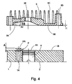
- Fig. 4 shows a so-called side valve engine, in an engine of this kind the valves 5, 5' are arranged in ducts 1A, 1'A in the engine block 1 adjacent to the piston 4.
- the principles of modification are the same as described above.
- the valve end 5'A does not move towards the upper surface 4A of the piston but towards a surface 3A inside the cylinder head 3.
- it is important to optimize modification of the cylinder head 3 so that the remaining play S2 between the valve top 5'A and the opposing surface 3A remains approx. 0.5 mm.
- a single-cylinder Otto engine provided with a supporting valve according to the invention, one starts out however by removing the cylinder head 3.
- the cylinder head 3 and engine block 1 are cleaned of residues of the old gasket 10.
- the valves are then positioned in their most extreme position, i.e. so that the valve 5' is in its most open position a set distance A from the cylinder wall in the cylinder head 3. In this position, it is measured (for example using a sliding calliper or dial test indicator) how great distance A is. The depth B in the top is then measured. Cutting, levelling and checking then takes place in the same way as above.
- Fig. 5 shows an air filter 8 intended to be used in a carburettor 6 that is provided with a non-removable fuel nozzle.
- the air filter 8 is provided with a choke element 8B that is provided with choke openings 8A.
- the choke openings are eight in number according to the practical example shown and consist of circular holes with a diameter of 4 mm. The total opening area through these holes is thus approx. 100 mm 2 .
- the area for the fastening screw that penetrates the centre hole (8C) in the choke element (8B) must be deducted here. It is also clear from the figure that the choke element (8B) is cup-shaped, with outer wall parts that are converging, so that the shape of a truncated cone is formed. This shape facilitates a simple, secure and tight fitting of the choke element (8B). It should be made clear that this form of modification is only a necessary alternative when the carburettor 6 is provided with a fixed non-modifiable fuel nozzle.
- Test 1 was carried out using Aspen environmental petrol in a new lawnmower.
- Tests 2 and 3 were carried out on a used lawnmower modified according to the invention.
- the propellant used in tests 2 and 3 is so-called E85, containing 85% ethanol and 15% petrol.
- Test 1 Type of fuel Emission Aspen environmental petrol Carbon monoxide (CO percent by vol.) Hydrocarbon (HC ppm) Carbon dioxide (CO 2 percent by vol.) Oxygen (O 2 percent by vol.) Idling speed 0.5 800 7.0 10.1 Working speed No-load engine 3.0 248 8.3 6.4 Working speed Engine under load 3.4 138 8.4 6.2
- Test 2 Type of fuel Emission Ethanol 85% Adjustable nozzle, adjusted to low running Carbon monoxide (CO percent by vol.) Hydrocarbon (HC ppm) Carbon dioxide (CO 2 percent by vol.) Oxygen (O 2 percent by vol.) Idling speed Working speed No-load engine 0.1 787 6.0 122 Working speed Engine under load 0.1 603 9.0 8.2 Test 3 Type of fuel Emission Ethanol 85% Adjustable nozzle, adjusted to steady running Carbon monoxide (CO percent by vol.) Hydrocarbon (HC ppm) Carbon dioxide (CO 2 percent by vol.) Oxygen (O 2 percent by vol.) Idling speed 1.8 183
- the invention is not restricted to what has been described above, but can be varied within the scope of the following claims.
- the invention can also be applied in application areas other than lawnmowers, for example other garden machinery and/or agricultural machinery.
- the existing play S1 between critical points in the engine can be measured in ways other than those described above, for example by means of laser meters or other existing measuring devices.
- the cylinder head it is also conceivable for the cylinder head to be cut by more than 100% of S1 and to use a thicker cylinder head gasket instead as compensation.
Landscapes
- Engineering & Computer Science (AREA)
- Chemical & Material Sciences (AREA)
- Combustion & Propulsion (AREA)
- Mechanical Engineering (AREA)
- General Engineering & Computer Science (AREA)
- Cylinder Crankcases Of Internal Combustion Engines (AREA)
- Developing Agents For Electrophotography (AREA)
- Apparatus For Radiation Diagnosis (AREA)
- Permanent Magnet Type Synchronous Machine (AREA)
Abstract
Description
- The present invention relates to a method for modifying a petrol-driven, single-cylinder Otto engine, which engine comprises an engine block with a cylinder, a cylinder head, a piston disposed movably inside the cylinder, a valve arranged by the cylinder, a carburettor with a fuel nozzle and an air filter arrangement.
- It is generally known that single-cylinder, petrol-driven Otto engines are major environmental culprits. Lawnmowers equipped with such engines come chiefly to mind here. Many different measures have been taken to try to reduce/eliminate the environmental pollution above all from lawnmowers. Amongst other things, lawnmowers have been developed that are operated electrically, either using a flex or rechargeable batteries. Battery-driven lawnmowers have a limitation on their operating time, however, that frequently provides insufficient capacity, and they are also still relatively expensive. Although flex-operated lawnmowers indeed do not have these disadvantages, the flex signifies a practical problem and also a safety risk. It can be stated that this trend in development with regard to lawnmowers has not solved the environmental problems, since the majority of users still want to use fuel-powered lawnmowers.
- To compensate for the environmental problem of fuel-driven lawnmowers to a certain extent, many large-scale users, e.g. local authorities, have gone over to using so-called environmental petrol, which is very expensive (approx. 2 euro/l). It is perceived that this extreme additional cost deters many potential users from buying this propellant.
- An alternative fuel that could solve both the environmental and cost problems is ethanol, which is a bio-fuel with combustion products that are on the whole environmentally friendly and which is priced at roughly the level of normal petrol. However, major manufacturers of single-cylinder Otto engines that are used in lawnmowers state that it is not possible to modify their single-cylinder Otto engines for ethanol operation, in spite of the fact that it has been known for over 100 years that Otto engines can de facto be powered by means of ethanol by using a relatively high compression ratio. Difficulties in cold starting are a general problem with ethanol as a fuel, however. It appears that this problem has contributed to the fact that development with regard to ethanol operation has led to increasingly sophisticated and thus expensive solutions. A sophisticated solution of this kind is previously known for example from
US 4,522,173 , in which direct injection is used and the piston in the engine is formed in a special manner with the aim of optimizing combustion.US 5,063,883 shows another sophisticated solution, a compensating piston mechanism being provided in connection with the combustion space, which compensating piston mechanism provides the possibility of varying the compression ratio, with the aim of being able to use a fuel like ethanol. Furthermore, reference can be made toWO 82/02576 - It has proved somewhat surprisingly to be the case that, contrary to the perception of current manufacturers, it is possible to convert a petrol-driven, single-cylinder Otto engine cost-effectively to satisfactorily functioning ethanol operation, which method is characterized by the following stages:
- a) measurement of the existing minimum play (S1) between the end (5A) of the valve in its extreme position in the open state and the surface (4A; 3A) facing said end (5A) of the valve,
- b) removal of the cylinder head (3),
- c) machining of the cylinder head (3), its surface (3B) facing the engine block (1) being cut and levelled by 40-100% of the existing minimum play (S1) to obtain a considerably smaller modified play (S2) between said valve end (5A) and said opposing surface (4A; 3A),
- d) checking that said modified play (S2) does not fall below a certain set value (SB),
- e) fitting of the cylinder head (3),
- f) adjustment of the fuel/air admixture so that an increase in the fuel flow in relation to the air flow is achieved,
- Thanks to the method described above, a modified single-cylinder Otto engine is obtained with which it is possible to use an environmentally friendly propellant A propellant known by the designation E85, which contains 85% ethanol and 15% petrol, is particularly suitable. Tests have shown that a drastic reduction in the CO emission can be obtained. Measurements have confirmed that it is possible to obtain a CO emission as low as 0.1 % in operation under load. In addition to the environmental advantage, the cost reduction is very large compared with using so-called environmental petrol, since the price of E85 is approx. 1/3 that of environmental petrol. Moreover, it has proved to be the case that the modified engine achieves higher efficiency, resulting in a further reduction in the fuel cost.
-
- Fig. 1
- shows a preferred modified single-cylinder Otto engine according to the invention in cross-section,
- Fig. 2
- shows an engine according to Fig. 1 in cross-section before modification,
- Fig. 3
- shows a carburettor for the engine according to Fig. 1 in cross-section,
- Fig. 3A
- shows a nozzle forming part of a carburettor according to Fig. 3,
- Fig. 4
- shows an alternative modified single-cylinder Otto engine according to the invention in cross-section, and
- Fig. 5
- shows a preferred air filter forming part of an engine according to Fig. 4.
- Fig. 1 shows a single-cylinder Otto engine with an overhead valve according to the invention in cross-section. An engine of this kind occurs extremely commonly mainly in manual lawnmowers, the engine power normally being approx. 3 - 5.5 hp (DIN). They are also common in so-called ride-on lawnmowers1, but the power is somewhat greater there, approx. 8-9 hp (DIN). The engine comprises an
engine block 1 with acylinder 2. Located on top of theengine block 1 is acylinder head 3. Thecylinder head 3 is provided withcooling fins 3C and an opening 3E for a spark plug. Furthermore, thecylinder head 3 is provided with throughholes 3D to screw thecylinder head 3 with its downward facingsurface 3B to thecylinder head 1. In thecylinder head 3 are two valve ducts 3F, located inside which arevalves 5, 5'. Thevalves 5, 5' are provided with a valve cone 5B that is intended to interact with avalve seat 5C in thecylinder head 3. Eachvalve 5 is provided with aflat surface 5A at its end. Situated between thecylinder head 3 and theengine block 1 is agasket 10. Amovable piston 4, which is provided at the top with an essentiallyflat surface 4A, is located inside thecylinder space 2. The engine also has a cup-type carburettor 6, with afuel nozzle 7 and apump mechanism 9. In addition, the engine is provided with anair filter 8. One important aspect of an engine according to the invention is that the play S2 between thevalve end 5A and theupper surface 4A of the piston in its upper position is extremely small, preferably approx. 0.4 - 0.6 mm. Another important aspect is that theopening 7A of the nozzle is sufficiently great to permit an adequate fuel inflow. Finally, it is a great advantage that the engine is equipped with apump mechanism 9 to be able to force fuel into the carburettor on start-up. - In connection with the modification of a single-cylinder Otto engine provided with an overhead valve according to the invention (see Fig. 2), one starts by laying the engine bare of necessary components such as the plastic cap and tank. The spark plug is then removed so that the spark plug opening (3E) is exposed. Then the engine is turned so that the valves are placed in their most extreme position, i.e. so that both valves (5, 5') are in their most open position a set distance (A) from the cylinder wall in the cylinder head (3). At the same time, it is ensured that the piston (4) is located in its upper extreme position, which according to the example shown here means that the piston top (4A) is on a level with the upper surface (1B) of the engine block (1). In this position the distance (S1) is measured between the valve end (5A) and the piston top (4A). This distance (S1) is also equal to the depth (B) in the cylinder head (3) minus the distance (A) that the valve end (5A) projects from the cylinder wall.
- The minimum distance S1 between the
end 5A of the valve and thelower surface 3B of the cylinder head is normally approx. 2-3 mm, i.e. B - A = S1, which is approx. 2-3 mm. With the aim of obtaining the optimum compression ratio to be able to use ethanol as a propellant, a part of the material in thecylinder head 3 must now be cut so that the play S1 between thepiston top 4A and thelower end 5A of the valve is reduced to a modified play S2 of between 0.4 - 1 mm (see Fig. 1). Thus thecylinder head 3 is machined by means of suitable cutting machining (e.g. milling or grinding) so that a greater part of the distance S1 is cut. More often than not, cutting of approx. 2-3 mm is required to have a remaining gap S2 between the valve ends 5A, 5A' and thepiston top 4A. When thecylinder head 3 has been machined down and levelled, it is held against theengine block 1 and the engine is turned round to check that novalve end 5A, 5'A strikes against thepiston top 4A. If this check turns out well, i.e. the play lies within the preferred range, the cylinder head is fitted to theengine block 1 with anew gasket 10. - Fig.3 shows a detailed view of a carburettor according to the invention. The
carburettor 6 is provided with a removable (via screw threads)fuel nozzle 7 in a known manner. Thecarburettor 6 is also provided with apump mechanism 9, a so-called "primer system" 9. Fig. 3A shows a detailed view of afuel nozzle 7 for thecarburettor 6. It is shown here that the diameter d, opening 7A in the fuel nozzle has been enlarged from approx. 0.6 mm - approx. 0.7 mm, i.e. an increase in the sectional area of more than 30%, for an engine with a power of approx. 4-5 hp. In engines of a somewhat higher power, e.g. 8-9 hp, the diameter d is normally approx. 0.75 mm. The diameter of the existingopening 7A is enlarged by approx. 5-20%, more preferredly approx. 10-15%, which is applicable in principle regardless of the engine's power within the above-mentioned ranges. To ascertain the optimum enlargement, the engine is tested in operation using a number of different fuel nozzles that are provided with different-sized openings. Thus when modifying the engine it is necessary to be equipped with a set consisting of a number of fuel nozzles with openings of different sizes. When the optimum fuel nozzle opening has thus been checked, a corresponding drill is used to enlarge the existingopening 7A to the desired size. - Fig. 4 shows a so-called side valve engine, in an engine of this kind the
valves 5, 5' are arranged inducts 1A, 1'A in theengine block 1 adjacent to thepiston 4. The principles of modification are the same as described above. In this case, however, the valve end 5'A does not move towards theupper surface 4A of the piston but towards asurface 3A inside thecylinder head 3. In the same way, however, it is important to optimize modification of thecylinder head 3 so that the remaining play S2 between the valve top 5'A and the opposingsurface 3A remains approx. 0.5 mm. In connection with modification of a single-cylinder Otto engine provided with a supporting valve according to the invention, one starts out however by removing thecylinder head 3. Following removal of thecylinder head 3, thecylinder head 3 andengine block 1 are cleaned of residues of theold gasket 10. The valves are then positioned in their most extreme position, i.e. so that the valve 5' is in its most open position a set distance A from the cylinder wall in thecylinder head 3. In this position, it is measured (for example using a sliding calliper or dial test indicator) how great distance A is. The depth B in the top is then measured. Cutting, levelling and checking then takes place in the same way as above. - Fig. 5 shows an
air filter 8 intended to be used in acarburettor 6 that is provided with a non-removable fuel nozzle. To be able to optimize the fuel/air mixture, theair filter 8 is provided with achoke element 8B that is provided withchoke openings 8A. The choke openings are eight in number according to the practical example shown and consist of circular holes with a diameter of 4 mm. The total opening area through these holes is thus approx. 100 mm2. This means a drastic reduction in the inlet area for feed air, since according to the original design (for petrol operation) the entire intake channel is open in principle for the flow of air, i.e. in the present case where the diameter is 34 mm an open area of between 800-900 mm2. The area for the fastening screw that penetrates the centre hole (8C) in the choke element (8B) must be deducted here. It is also clear from the figure that the choke element (8B) is cup-shaped, with outer wall parts that are converging, so that the shape of a truncated cone is formed. This shape facilitates a simple, secure and tight fitting of the choke element (8B). It should be made clear that this form of modification is only a necessary alternative when thecarburettor 6 is provided with a fixed non-modifiable fuel nozzle. - In comparative tests that have been carried out, surprisingly good results have been able to be demonstrated with the invention with regard to environmental effects. The results of three different tests carried out are shown below.
Test 1 was carried out using Aspen environmental petrol in a new lawnmower.Tests tests Test 1Type of fuel Emission Aspen environmental petrol Carbon monoxide (CO percent by vol.) Hydrocarbon (HC ppm) Carbon dioxide (CO2 percent by vol.) Oxygen (O2 percent by vol.) Idling speed 0.5 800 7.0 10.1 Working speed No-load engine 3.0 248 8.3 6.4 Working speed Engine under load 3.4 138 8.4 6.2 Test 2Type of fuel Emission Ethanol 85% Adjustable nozzle, adjusted to low running Carbon monoxide (CO percent by vol.) Hydrocarbon (HC ppm) Carbon dioxide (CO2 percent by vol.) Oxygen (O2 percent by vol.) Idling speed Working speed No-load engine 0.1 787 6.0 122 Working speed Engine under load 0.1 603 9.0 8.2 Test 3Type of fuel Emission Ethanol 85% Adjustable nozzle, adjusted to steady running Carbon monoxide (CO percent by vol.) Hydrocarbon (HC ppm) Carbon dioxide (CO2 percent by vol.) Oxygen (O2 percent by vol.) Idling speed 1.8 183 8.4 7.6 Working speed No-load engine 2.3 168 9.0 5.9 Working speed Engine under load 0.1 140 9.0 8.0 - The results show that a modified engine according to the invention under load, using E85 as a propellant, has exceptionally a much lower CO emission than
test 1. The CO emission for an engine under load was only 0.1 % CO, while a lawnmower operated using Aspen environmental petrol emitted 3.4 % CO when under load. The other values regarding emissions are roughly comparable. The test thus shows that an engine modified according to the invention facilitates a drastic reduction in the environmentally harmful CO emission. We have chosen to focus on the emission levels for an engine under load, since a lawnmower operates de facto under load during the greater period of its operation. However, it can be noted that the CO emission is otherwise also good with regard to an engine modified according to an embodiment of the invention. - It has also proved to be the case that an engine converted in accordance with the invention can meet the high requirements that apply to obtain environmental labelling according to the Swan standard, ISO 14024. In a test carried out according to test cycle G1 in ISO 8178, by the certified testing institute MTC, the following very good exhaust values were measured for a Briggs & Stratton Intek Edge 55 OHV (without catalyzer) that had been modified according to an embodiment of the invention.
Briggs & Stratton Intek Edge 55 OHV (without catalyzer) CO HC CO2 NOX BF (g/kWh) (g/kWh) (g/kWh) (g/kWh) (g/kWh) Test 110.42 2.28 891 7.73 437.5 Test 210.27 1.98 906 7.90 443.9 Mean 10.34 2.13 898 7.82 440.7 - The invention is not restricted to what has been described above, but can be varied within the scope of the following claims. Thus it is perceived inter alia that the invention can also be applied in application areas other than lawnmowers, for example other garden machinery and/or agricultural machinery. Furthermore, it is perceived that the existing play S1 between critical points in the engine can be measured in ways other than those described above, for example by means of laser meters or other existing measuring devices. In certain extreme cases it is also conceivable for the cylinder head to be cut by more than 100% of S1 and to use a thicker cylinder head gasket instead as compensation.
Claims (6)
- Method for modifying a petrol-driven, single-cylinder Otto engine, which engine comprises an engine block (1) with a cylinder (2), a cylinder head (3), a piston (4) disposed movably inside the cylinder, two valves (5, 5') arranged by the cylinder, a carburettor (6) with a fuel nozzle (7) and an air filter arrangement (8), characterized in that the method comprises the following stages:a) measurement of the existing minimum play (S1) between the end (5A) of the valve in its extreme position in the open state and the surface (4A; 3A) facing said end (5A) of the valve,b) removal of the cylinder head (3),c) machining of the cylinder head (3), its surface (3B) facing the engine block (1) being cut and levelled by 40-100% of the existing minimum play (S1) to obtain a considerably smaller modified play (S2) between said valve end (5A) and said opposing surface (4A; 3A),d) checking that said modified play (S2) does not fall below a certain set value (SB),e) fitting of the cylinder head (3),f) adjustment of the fuel/air admixture so that an increase in the fuel flow in relation to the air flow is achieved,following which the engine has been modified for operation by means of a fuel mainly containing ethanol.
- Method according to claim 1, characterized in that it is ensured that said carburettor (6) is provided with a pump mechanism (9) to be able to force fuel into said carburettor (6).
- Method according to claim 1, characterized in that the checking according to stage d) is carried out by placing the cylinder head on top of the engine block without a gasket to ensure that none of said valve ends (5A, 5A') strike said opposing surface (4A; 3A,), following which the cylinder head (3) is fitted with a cylinder head gasket (10).
- Method according to claim 1, characterized in that said carburettor (6) is provided with a removable fuel nozzle and stage f) comprises the following steps:1) removal of the fuel nozzle (7),2) enlargement of the opening (6A) in the fuel nozzle (7) by 5-20%, preferably 8-15%, more preferredly approx. 10%,3) fitting of the enlarged fuel nozzle (7).
- Method according to claim 4, characterized in that between stages 1) and 2) a set of prefabricated fuel nozzles with different-sized openings is used to check the optimum opening size for the current engine before the opening (7A) in the engine's own fuel nozzle (7) is finally enlarged.
- Method according to claim 1, characterized in that the carburettor is provided with a fixed non-modifiable fuel nozzle, stage f) being achieved by said air filter (8) being provided with a choke element (8A, 8B) that reduces the existing inlet area for feed air by 70-95%, preferably 80-95%, more preferredly approx. 85-90%.
Priority Applications (1)
| Application Number | Priority Date | Filing Date | Title |
|---|---|---|---|
| EP07106894A EP1808587A3 (en) | 2001-03-13 | 2002-03-12 | Modified single-cylinder otto engine |
Applications Claiming Priority (3)
| Application Number | Priority Date | Filing Date | Title |
|---|---|---|---|
| SE0100867A SE519535C2 (en) | 2001-03-13 | 2001-03-13 | Modified single-cylinder ottomotor |
| SE0100867 | 2001-03-13 | ||
| PCT/SE2002/000439 WO2002073015A1 (en) | 2001-03-13 | 2002-03-12 | Modified otto engine with one cylinder |
Related Child Applications (1)
| Application Number | Title | Priority Date | Filing Date |
|---|---|---|---|
| EP07106894A Division EP1808587A3 (en) | 2001-03-13 | 2002-03-12 | Modified single-cylinder otto engine |
Publications (2)
| Publication Number | Publication Date |
|---|---|
| EP1383994A1 EP1383994A1 (en) | 2004-01-28 |
| EP1383994B1 true EP1383994B1 (en) | 2007-08-15 |
Family
ID=20283338
Family Applications (2)
| Application Number | Title | Priority Date | Filing Date |
|---|---|---|---|
| EP07106894A Withdrawn EP1808587A3 (en) | 2001-03-13 | 2002-03-12 | Modified single-cylinder otto engine |
| EP02703025A Expired - Lifetime EP1383994B1 (en) | 2001-03-13 | 2002-03-12 | Modified otto engine with one cylinder |
Family Applications Before (1)
| Application Number | Title | Priority Date | Filing Date |
|---|---|---|---|
| EP07106894A Withdrawn EP1808587A3 (en) | 2001-03-13 | 2002-03-12 | Modified single-cylinder otto engine |
Country Status (5)
| Country | Link |
|---|---|
| EP (2) | EP1808587A3 (en) |
| AT (1) | ATE370320T1 (en) |
| DE (1) | DE60221816T2 (en) |
| SE (1) | SE519535C2 (en) |
| WO (1) | WO2002073015A1 (en) |
Families Citing this family (2)
| Publication number | Priority date | Publication date | Assignee | Title |
|---|---|---|---|---|
| US7905469B2 (en) | 2007-05-25 | 2011-03-15 | Briggs and Statton Corporation | Gaseous fuel mixing device |
| US8196901B2 (en) | 2009-01-09 | 2012-06-12 | Briggs & Stratton Corporation | System and method for converting an engine to an alternate fuel |
Family Cites Families (16)
| Publication number | Priority date | Publication date | Assignee | Title |
|---|---|---|---|---|
| US871134A (en) * | 1906-03-13 | 1907-11-19 | Joseph Gabriel Pierre Marie Monnier | Carbureter. |
| US1885331A (en) * | 1929-11-05 | 1932-11-01 | Collins Douglas | Automatic choke |
| US2737170A (en) * | 1951-01-18 | 1956-03-06 | Gen Motors Corp | High compression combustion chambers |
| US2725865A (en) * | 1952-05-28 | 1955-12-06 | Gen Motors Corp | Combustion chamber |
| US3089685A (en) * | 1960-05-09 | 1963-05-14 | Acf Ind Inc | Carburetor |
| FR2071298A5 (en) * | 1969-12-23 | 1971-09-17 | Sibe | |
| US4216744A (en) * | 1976-03-08 | 1980-08-12 | Agence Nationale De Valorisation De La Recherche (Anvar) | Engine whose fuel is a product other than a petroleum product |
| BE873331A (en) * | 1978-01-16 | 1979-07-05 | Engelhard Min & Chem | COMBUSTION CONTROL DEVICE FOR AN INTERNAL COMBUSTION ENGINE USING FUELS WITH A VARIABLE PROPORTION OF PARTLY OXIDIZED HYDROCARBONS |
| US4235828A (en) * | 1979-06-20 | 1980-11-25 | Howes Leslie D | Fuel economizer employing improved turbulent mixing of fuel and air |
| AU6707281A (en) * | 1981-01-21 | 1982-08-16 | Norman Stinson Ritchie | Fuel efficient variable capacity internal combustion engine, with microprocessor engine control |
| JPS57203851A (en) * | 1981-06-06 | 1982-12-14 | Daihatsu Motor Co Ltd | Internal-combustion engine capable of using various kinds of fuel |
| JPS60176820A (en) * | 1984-02-23 | 1985-09-10 | Honda Motor Co Ltd | Vehicles and internal combustion engines that can use multiple types of fuel |
| US4826517A (en) * | 1988-04-29 | 1989-05-02 | Bendix Electronics Limited | Disposable air cleaner with one piece housing |
| US5063883A (en) * | 1989-01-19 | 1991-11-12 | Dingess Billy E | Detonation control device for an internal combustion engine |
| US6120007A (en) * | 1996-02-13 | 2000-09-19 | Grant; Barry | Carburetor with color-coded interchangeable components |
| US5868117A (en) * | 1997-10-29 | 1999-02-09 | Chrysler Corporation | Method of determining ethanol thresholds in a flexible fueled vehicle |
-
2001
- 2001-03-13 SE SE0100867A patent/SE519535C2/en not_active IP Right Cessation
-
2002
- 2002-03-12 DE DE60221816T patent/DE60221816T2/en not_active Expired - Fee Related
- 2002-03-12 EP EP07106894A patent/EP1808587A3/en not_active Withdrawn
- 2002-03-12 AT AT02703025T patent/ATE370320T1/en not_active IP Right Cessation
- 2002-03-12 EP EP02703025A patent/EP1383994B1/en not_active Expired - Lifetime
- 2002-03-12 WO PCT/SE2002/000439 patent/WO2002073015A1/en not_active Ceased
Also Published As
| Publication number | Publication date |
|---|---|
| ATE370320T1 (en) | 2007-09-15 |
| SE0100867L (en) | 2002-09-14 |
| WO2002073015A1 (en) | 2002-09-19 |
| SE519535C2 (en) | 2003-03-11 |
| SE0100867D0 (en) | 2001-03-13 |
| EP1383994A1 (en) | 2004-01-28 |
| EP1808587A2 (en) | 2007-07-18 |
| EP1808587A3 (en) | 2007-10-03 |
| DE60221816D1 (en) | 2007-09-27 |
| DE60221816T2 (en) | 2008-05-08 |
Similar Documents
| Publication | Publication Date | Title |
|---|---|---|
| EP0957245B1 (en) | Engine using liquid and/or gaseous fuel and method of operating the same | |
| CA2027875C (en) | Combustion system for dual fuel engine | |
| EP2025903B1 (en) | Internal combustion engine | |
| KR100581593B1 (en) | Ignition plugs for internal combustion engine | |
| EP0146549A1 (en) | Ignition-assisted fuel combustion system. | |
| WO2009114264A1 (en) | Pre-chamber | |
| US7628130B2 (en) | Ignition spark plug | |
| BRPI0713716A2 (en) | multiple fuel internal combustion engine | |
| EP1174608A3 (en) | Dual fuel compression Ignition Engine | |
| US5752481A (en) | Injection valve assembly for an internal combustion engine | |
| WO2003089785A3 (en) | Improved two-valve high squish flow i.c. engine | |
| KR100584015B1 (en) | Engine conversion | |
| EP1808587A2 (en) | Modified single-cylinder otto engine | |
| US7284524B2 (en) | Cylinder head assemblies | |
| Phatak et al. | Investigation of a spark-assisted diesel engine | |
| WO1999040302A8 (en) | Barrier divided combustion chamber for fuel injected two-stroke engine | |
| US6394056B1 (en) | Internal combustion engine | |
| US5230313A (en) | Gas engine cylinder head, and a method of retrofitting the head with a precombustion chamber unit | |
| Kubesh | Development of a throttleless natural gas engine | |
| GB1581689A (en) | Internal combustion engine | |
| EP1702155B1 (en) | Method of optimizing fuel injection timing in a locomotive engine | |
| EP1314870B1 (en) | Enhanced two-stroke endothermic engine | |
| CN121047689B (en) | Engine control methods and engines | |
| WO1985001318A1 (en) | Piston having fuel diverting barrier means | |
| Knaus et al. | A New High-Performance Four-Stroke Engine for All-Position Use in Hand-Held Power Tools |
Legal Events
| Date | Code | Title | Description |
|---|---|---|---|
| PUAI | Public reference made under article 153(3) epc to a published international application that has entered the european phase |
Free format text: ORIGINAL CODE: 0009012 |
|
| 17P | Request for examination filed |
Effective date: 20030918 |
|
| AK | Designated contracting states |
Kind code of ref document: A1 Designated state(s): AT BE CH CY DE DK ES FI FR GB GR IE IT LI LU MC NL PT SE TR |
|
| AX | Request for extension of the european patent |
Extension state: AL LT LV MK RO SI |
|
| RAP1 | Party data changed (applicant data changed or rights of an application transferred) |
Owner name: GGP SWEDEN AB |
|
| 17Q | First examination report despatched |
Effective date: 20061107 |
|
| GRAP | Despatch of communication of intention to grant a patent |
Free format text: ORIGINAL CODE: EPIDOSNIGR1 |
|
| RIC1 | Information provided on ipc code assigned before grant |
Ipc: F02B 75/04 20060101AFI20070418BHEP |
|
| GRAS | Grant fee paid |
Free format text: ORIGINAL CODE: EPIDOSNIGR3 |
|
| GRAA | (expected) grant |
Free format text: ORIGINAL CODE: 0009210 |
|
| RIN1 | Information on inventor provided before grant (corrected) |
Inventor name: ERIKSSON, GOERAN |
|
| 111Z | Information provided on other rights and legal means of execution |
Free format text: ATBECHCYDEDKESFIFRGBGRIEITLUMCNLPTSETR Effective date: 20070702 |
|
| AK | Designated contracting states |
Kind code of ref document: B1 Designated state(s): AT BE CH CY DE DK ES FI FR GB GR IE IT LI LU MC NL PT SE TR |
|
| REG | Reference to a national code |
Ref country code: GB Ref legal event code: FG4D |
|
| REG | Reference to a national code |
Ref country code: CH Ref legal event code: EP |
|
| REG | Reference to a national code |
Ref country code: IE Ref legal event code: FG4D |
|
| REF | Corresponds to: |
Ref document number: 60221816 Country of ref document: DE Date of ref document: 20070927 Kind code of ref document: P |
|
| REG | Reference to a national code |
Ref country code: SE Ref legal event code: TRGR |
|
| PG25 | Lapsed in a contracting state [announced via postgrant information from national office to epo] |
Ref country code: ES Free format text: LAPSE BECAUSE OF FAILURE TO SUBMIT A TRANSLATION OF THE DESCRIPTION OR TO PAY THE FEE WITHIN THE PRESCRIBED TIME-LIMIT Effective date: 20071126 Ref country code: FI Free format text: LAPSE BECAUSE OF FAILURE TO SUBMIT A TRANSLATION OF THE DESCRIPTION OR TO PAY THE FEE WITHIN THE PRESCRIBED TIME-LIMIT Effective date: 20070815 |
|
| PG25 | Lapsed in a contracting state [announced via postgrant information from national office to epo] |
Ref country code: AT Free format text: LAPSE BECAUSE OF FAILURE TO SUBMIT A TRANSLATION OF THE DESCRIPTION OR TO PAY THE FEE WITHIN THE PRESCRIBED TIME-LIMIT Effective date: 20070815 Ref country code: CH Free format text: LAPSE BECAUSE OF FAILURE TO SUBMIT A TRANSLATION OF THE DESCRIPTION OR TO PAY THE FEE WITHIN THE PRESCRIBED TIME-LIMIT Effective date: 20070815 Ref country code: LI Free format text: LAPSE BECAUSE OF FAILURE TO SUBMIT A TRANSLATION OF THE DESCRIPTION OR TO PAY THE FEE WITHIN THE PRESCRIBED TIME-LIMIT Effective date: 20070815 |
|
| REG | Reference to a national code |
Ref country code: CH Ref legal event code: PL |
|
| ET | Fr: translation filed | ||
| PG25 | Lapsed in a contracting state [announced via postgrant information from national office to epo] |
Ref country code: BE Free format text: LAPSE BECAUSE OF FAILURE TO SUBMIT A TRANSLATION OF THE DESCRIPTION OR TO PAY THE FEE WITHIN THE PRESCRIBED TIME-LIMIT Effective date: 20070815 |
|
| PG25 | Lapsed in a contracting state [announced via postgrant information from national office to epo] |
Ref country code: DK Free format text: LAPSE BECAUSE OF FAILURE TO SUBMIT A TRANSLATION OF THE DESCRIPTION OR TO PAY THE FEE WITHIN THE PRESCRIBED TIME-LIMIT Effective date: 20070815 Ref country code: GR Free format text: LAPSE BECAUSE OF FAILURE TO SUBMIT A TRANSLATION OF THE DESCRIPTION OR TO PAY THE FEE WITHIN THE PRESCRIBED TIME-LIMIT Effective date: 20071116 |
|
| PG25 | Lapsed in a contracting state [announced via postgrant information from national office to epo] |
Ref country code: PT Free format text: LAPSE BECAUSE OF FAILURE TO SUBMIT A TRANSLATION OF THE DESCRIPTION OR TO PAY THE FEE WITHIN THE PRESCRIBED TIME-LIMIT Effective date: 20080115 |
|
| PGFP | Annual fee paid to national office [announced via postgrant information from national office to epo] |
Ref country code: GB Payment date: 20080317 Year of fee payment: 7 Ref country code: NL Payment date: 20080325 Year of fee payment: 7 Ref country code: SE Payment date: 20080326 Year of fee payment: 7 |
|
| PLBE | No opposition filed within time limit |
Free format text: ORIGINAL CODE: 0009261 |
|
| STAA | Information on the status of an ep patent application or granted ep patent |
Free format text: STATUS: NO OPPOSITION FILED WITHIN TIME LIMIT |
|
| 26N | No opposition filed |
Effective date: 20080516 |
|
| PGFP | Annual fee paid to national office [announced via postgrant information from national office to epo] |
Ref country code: DE Payment date: 20080325 Year of fee payment: 7 Ref country code: FR Payment date: 20080229 Year of fee payment: 7 |
|
| PGFP | Annual fee paid to national office [announced via postgrant information from national office to epo] |
Ref country code: BE Payment date: 20080320 Year of fee payment: 7 |
|
| PGFP | Annual fee paid to national office [announced via postgrant information from national office to epo] |
Ref country code: IT Payment date: 20080329 Year of fee payment: 7 |
|
| PG25 | Lapsed in a contracting state [announced via postgrant information from national office to epo] |
Ref country code: MC Free format text: LAPSE BECAUSE OF NON-PAYMENT OF DUE FEES Effective date: 20080331 |
|
| PG25 | Lapsed in a contracting state [announced via postgrant information from national office to epo] |
Ref country code: IE Free format text: LAPSE BECAUSE OF NON-PAYMENT OF DUE FEES Effective date: 20080312 |
|
| PG25 | Lapsed in a contracting state [announced via postgrant information from national office to epo] |
Ref country code: CY Free format text: LAPSE BECAUSE OF FAILURE TO SUBMIT A TRANSLATION OF THE DESCRIPTION OR TO PAY THE FEE WITHIN THE PRESCRIBED TIME-LIMIT Effective date: 20070815 |
|
| BERE | Be: lapsed |
Owner name: GGP SWEDEN A.B. Effective date: 20090331 |
|
| EUG | Se: european patent has lapsed | ||
| GBPC | Gb: european patent ceased through non-payment of renewal fee |
Effective date: 20090312 |
|
| NLV4 | Nl: lapsed or anulled due to non-payment of the annual fee |
Effective date: 20091001 |
|
| REG | Reference to a national code |
Ref country code: FR Ref legal event code: ST Effective date: 20091130 |
|
| PG25 | Lapsed in a contracting state [announced via postgrant information from national office to epo] |
Ref country code: DE Free format text: LAPSE BECAUSE OF NON-PAYMENT OF DUE FEES Effective date: 20091001 |
|
| PG25 | Lapsed in a contracting state [announced via postgrant information from national office to epo] |
Ref country code: NL Free format text: LAPSE BECAUSE OF NON-PAYMENT OF DUE FEES Effective date: 20091001 |
|
| PG25 | Lapsed in a contracting state [announced via postgrant information from national office to epo] |
Ref country code: FR Free format text: LAPSE BECAUSE OF NON-PAYMENT OF DUE FEES Effective date: 20091123 Ref country code: GB Free format text: LAPSE BECAUSE OF NON-PAYMENT OF DUE FEES Effective date: 20090312 |
|
| PG25 | Lapsed in a contracting state [announced via postgrant information from national office to epo] |
Ref country code: LU Free format text: LAPSE BECAUSE OF NON-PAYMENT OF DUE FEES Effective date: 20080312 |
|
| PG25 | Lapsed in a contracting state [announced via postgrant information from national office to epo] |
Ref country code: TR Free format text: LAPSE BECAUSE OF FAILURE TO SUBMIT A TRANSLATION OF THE DESCRIPTION OR TO PAY THE FEE WITHIN THE PRESCRIBED TIME-LIMIT Effective date: 20070815 |
|
| PG25 | Lapsed in a contracting state [announced via postgrant information from national office to epo] |
Ref country code: IT Free format text: LAPSE BECAUSE OF NON-PAYMENT OF DUE FEES Effective date: 20090312 |
|
| PG25 | Lapsed in a contracting state [announced via postgrant information from national office to epo] |
Ref country code: SE Free format text: LAPSE BECAUSE OF NON-PAYMENT OF DUE FEES Effective date: 20090313 |