Technical Field
The present invention relates to an electrode for the use in a fuel cell and to a
fuel cell using the electrode.
Background Art
In general, a fuel cell includes a positive electrode, a negative electrode, and an
electrolyte (electrolytic solution) disposed therebetween. The fuel cell generates power
by feeding oxygen (or air) as an oxidizer to the positive electrode and hydrogen as a
fuel to the negative electrode, which induce an electrochemical reaction.
In the electrochemical reaction at each electrode, a reaction represented by the
following formula (1) occurs at the negative electrode, while a reaction represented by
the following formula (2) occurs at the positive electrode:
H2 → 2H+ + 2e-
1/2O2 + 2H+ +2e- → H2O
Fuel cells are classified into various types depending on the types of the electrolytes.
Typically, the fuel cells are roughly classified into an alkali type, a solid polymer
electrolyte type, a phosphoric acid type, a fused carbonate type, and a solid electrolyte
type. Among them, the solid polymer fuel cell is noted at present, since such cell can
generate power as high as 1 A/cm2 or more at normal temperature and normal pressure.
The solid polymer fuel cell includes an ion exchange membrane such as a perfluorosulfonic
acid film as an electrolyte, and respective electrodes, i.e., negative and positive
electrodes, adhered to both surfaces of the ion exchange film. Each electrode comprises
a mixture of a polymer solid electrolyte and carbon substances carrying a catalytic material.
In such a construction, hydrogen gas fed to the negative electrode reaches the
catalyst through pores of the electrode, and is converted to hydrogen ions by removing
electrons with the aid of the catalyst. The hydrogen ions reach the positive electrode
through the electrolytes within the electrodes and the solid polymer electrolyte membrane
between the electrodes. Then, oxygen fed to the positive electrode is reacted with
electrons flowed via an external circuit to produce water, as represented by the above-described
equations.
The electrons removed from hydrogen are evolved to the external circuit through
a catalyst carrier within the electrodes, and flow into the positive electrode via the external
circuit. As a result, the electrons flow from the negative electrode to the positive
electrode in the external circuit to generate power.
In order to improve the properties of the solid polymer fuel cell, a catalytic material
having high catalytic activity should be used. Also, the electrode should have improved
properties. In other words, hydrogen gas and oxygen gas for use in the electrode
reactions should be well-diffused in the electrodes, and hydrogen ions and electrons
generated by the electrode reactions should be highly conductive. Accordingly, the
electrodes have a porous structure including a number of pores. In the porous structure,
the solid polymer electrolyte is combined with the carbon substances carrying the catalytic
material. The solid polymer electrolyte becomes a hydrogen ion conductive channel,
and the carbon substances become an electron conductive channel. The pores function
as feed and discharge channels of oxygen gas, hydrogen gas and purified water. In
view of the above, a fine structure of each electrode, an improved production method,
and a controlled solid polymer electrolyte amount in each electrode are important factors
for improving the properties.
The amount and the dispersibility of the catalytic material carried vary dependent
on the properties and the fine structure of the carbon substances. Therefore, catalytic
activity is significantly different. Conductivities of the reaction gas, hydrogen ions
and electrons vary depending on the structures of the carbon substances, i.e., pore distribution.
Thus, the fuel cell properties may be changed greatly. For example, when the
carbon substances have a large average particle size and the electrodes have small specific
surface areas, the amount of the catalytic material carried is decreased and the dispersibility
is lowered, whereby the fuel cell properties tend to be decreased. On the
other hand, when the carbon substances have a very small average particle size, the
pores have very small, and the electrodes have very large specific surface areas, the
amount of the catalytic material carried is increased. However, the catalytic efficiency
is decreased since the conductivities of the reaction gas and the like are significantly
decreased and the solid polymer electrolyte cannot be penetrated into the pores. It may
be difficult to improve the fuel cell properties.
In summary, the properties of a fuel cell, especially a solid polymer fuel cell,
cannot be sufficiently improved without optimizing the structure and the shape of the
carbon substances.
Hitherto, almost no review has been made on the correlation of the fine structures
of the carbon substances in a solid polymer fuel cell electrode with the properties
of the fuel cell. At present, optimum properties cannot be yet provided, although various
solid polymer fuel cells have been produced using various carbon substances including
active carbon.
Disclosure of the Invention
An object of the present invention is to provide a fuel cell electrode showing
high catalyst activity by carrying a catalytic material with high dispersibility, having
excellent gas diffusion, and having high hydrogen ion conductivity and electron mobility.
Another object of the present invention is to provide a method of producing the
fuel cell electrode.
Still another object of the present invention is to provide a fuel cell comprising
the fuel cell electrode.
Still another object of the present invention is to provide a method of producing
the fuel cell comprising the fuel cell electrode.
A first aspect of the present invention is a solid polymer electrolyte - catalyst
combined fuel cell electrode comprising a solid polymer electrolyte and carbon particles
carrying a catalytic material, wherein the carbon particles are monolayer carbon nano-hom
aggregates in which monolayer carbon nano-horns are aggregated spherically.
A second aspect of the present invention is a solid polymer fuel cell, which comprises
two electrodes at both surfaces of the solid polymer electrode films, wherein at
least one of the electrodes includes a catalytic layer comprising a solid polymer electrolyte
and carbon particles carrying a catalytic material, the catalytic layer being formed
on one side of a gas diffusion layer, and wherein the carbon particles are monolayer
carbon nano-horn aggregates in which monolayer carbon nano-horns are aggregated
spherically.
A third aspect of the present invention is a method of producing a solid polymer
fuel cell with any one of the above-mentioned solid polymer electrolyte - catalyst combined
fuel cell electrodes, which comprises the step of forming and pressing the solid
polymer electrolyte - catalyst combined fuel cell electrode including the monolayer carbon
nano-hom aggregates to a solid polymer electrode film to produce an electrode-electrolyte
integrated matter.
A fourth aspect of the present invention is a method of producing a solid polymer
fuel cell electrode, which comprises the steps of: mixing monolayer carbon nano-horn
aggregates with an organic compound solution or a mixed solution including at
least one of the gold and platinum group metals or an alloy thereof, adding a reducing
agent to produce catalyst particles of the gold and platinum group metals or an alloy
thereof, whereby the carbon particles of the monolayer carbon nano-hom aggregates
carry the catalyst particles, adding a colloid dispersion of a polymer electrolyte to the
carbon particles so that the colloids are adsorbed on the carbon particles and the colloid
dispersion becomes a paste, and applying, heating and drying the paste on a carbon paper.
A fifth aspect of the present invention is a method of producing a solid polymer
fuel cell, which comprises the steps of: mixing monolayer carbon nano-horn aggregates
with an organic compound solution or a mixed solution including at least one of the
gold and platinum group metals or an alloy thereof, adding a reducing agent to produce
catalyst particles of gold and platinum group metals or an alloy thereof, whereby the
carbon particles of the monolayer carbon nano-horn aggregates carry the catalyst particles,
adding a colloid dispersion of a polymer electrolyte to the carbon particles so that
the colloids are adsorbed on the carbon particles and the colloid dispersion becomes a
paste, applying, heating and drying the paste on a carbon paper, and forming and pressing
the carbon paper to at least one surface of a solid polymer electrolyte sheet to produce
a single cell.
A sixth aspect of the present invention is a fuel cell electrode, which comprises
carbon substances carrying at least a catalytic material, wherein the carbon substances
are aggregates including at least one type of carbon molecules in which six-member
rings including carbon atoms constitute a rotational form and at least one end of the
rotational form is closed.
A seventh aspect of the present invention is a fuel cell electrode, which comprises
carbon substances carrying at least a catalytic material, wherein the carbon substances
are aggregates including at least one type of carbon molecules in a spherical
form in which six-member rings including carbon atoms constitute a rotational form.
An eighth aspect of the present invention is a fuel cell comprising any one of the
above-mentioned fuel cell electrodes.
A ninth aspect of the present invention is a solid polymer fuel cell electrode,
wherein the carbon substances and the solid polymer electrolyte form a combined matter.
A tenth aspect of the present invention is a solid polymer fuel cell comprising
the solid polymer fuel cell electrode.
An eleventh aspect of the present invention is a solid polymer fuel cell, which
comprises two electrodes at both surfaces of the solid polymer electrode films, wherein
at least one of the electrodes includes a catalytic layer comprising a solid polymer electrolyte
and carbon substances carrying a solid polymer electrolyte, the catalytic layer
being formed on one side of a gas diffusion layer, and wherein the carbon substances in
the catalytic layer are aggregates including at least one type of carbon molecules in
which six-member rings including carbon atoms constitute a rotational form and at least
one end of the rotational form is closed.
A twelfth aspect of the present invention is a solid polymer fuel cell, which
comprises two electrodes at both surfaces of the solid polymer electrode films, wherein
at least one of the electrodes includes a catalytic layer comprising a solid polymer electrolyte
and carbon substances carrying a solid polymer electrolyte, the catalytic layer
being formed on one side of a gas diffusion layer, and wherein the carbon substances in
the catalytic layer are aggregates including at least one type of carbon molecules in a
spherical form in which six-member rings including carbon atoms constitute a rotational
form.
A thirteenth aspect of the present invention is a fuel cell electrode, which comprises
carbon substances carrying at least a catalytic material, wherein the carbon substances
are carbon nano-horn aggregates.
A fourteenth aspect of the present invention is any one of the above-mentioned
solid polymer fuel cell electrodes, wherein the carbon substances and the solid polymer
electrolyte form a combined matter.
A fifteenth aspect of the present invention is a fuel cell comprising any one of
the above-mentioned fuel cell electrodes.
A sixteenth aspect of the present invention is a solid polymer fuel cell comprising
the solid polymer fuel cell electrode.
A seventeenth aspect of the present invention is a solid polymer fuel cell, which
comprises electrodes at both surfaces of the solid polymer electrode films, wherein at
least one of the electrodes includes a catalytic layer comprising a solid polymer electrolyte
and carbon substances carrying a catalytic material, the catalytic layer being formed
on one side of a gas diffusion layer, and wherein the carbon substances in the catalytic
layer are carbon nano-horn aggregates.
An eighteenth aspect of the present invention is a carbon nano-horn aggregate
for use in a fuel cell.
A nineteenth aspect of the present invention is a carbon nano-horn aggregate for
use in an electrode material of a fuel cell.
A twentieth aspect of the present invention is a carbon nano-horn aggregate for
use in a solid polymer fuel cell.
A twenty-first aspect of the present invention is a carbon nano-hom aggregate
for use in an electrode material of a solid polymer fuel cell.
A twenty-second aspect of the present invention is a method of producing a solid
polymer fuel cell with a solid polymer electrolyte - catalyst combined fuel cell electrode,
which comprises the step of forming and pressing the solid polymer electrolyte-catalyst
combined fuel cell electrode including the monolayer carbon nano-horn aggregates
to a solid polymer electrode film to produce an electrode - electrolyte integrated
matter.
Brief Description of the Drawings
Fig. 1 is a conceptual view of an example of a monolayer carbon nano-horn aggregate
used in a solid polymer electrolyte - catalyst combined electrode according to
the present invention.
Fig. 2 is a basic structure of an example of a solid polymer electrolyte - catalyst
combined electrode comprising monolayer carbon nano-hom aggregates according to
the present invention.
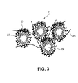
Fig. 3 is a conceptual view of an example of carbon nano-horn aggregates used
in a fuel cell electrode according to the present invention.
Best Mode for Carrying Out the Invention
Referring to the figures, the fuel cell electrode and the fuel cell comprising the
same according to the present invention will be described below in detail.
According to the present invention, a fuel cell electrode comprises carbon substances
carrying at least a catalytic material, wherein the carbon substances are aggregates
including at least one type of carbon molecules in which six-member rings including
carbon atoms constitute a rotational form and at least one end of the rotational form
is closed.
The term "six-member rings including carbon atoms constitute a rotational form"
herein means a structure that six-member rings including carbon atoms are disposed
along a surface of a rotational form. In other words, the flat surfaces of the six-member
rings are disposed along a surface constituting the rotational form. The term "rotational
form" herein means not only a complete cylinder or cone, but also irregular shapes with
non-uniform diameters, bent shapes, distorted shapes, and shapes with convexoconcave
sides. The rotational form has a section that is not only a complete circle, but also an
ellipse or different shapes with respect to the area of the section. The six-member rings
including carbon atoms are disposed not only on a regular basis, but also on an irregular
basis. In addition, the six-member rings are arranged not only perpendicularly, or at a
predetermined angle to the axes, but also irregularly. In some cases, the six-member
rings are arranged spirally to the axes.
At least one end of the carbon molecules may be closed. The carbon molecules
may be closed in any shape, i.e., in cone shape. It is also contemplated that carbon five-member
or seven-member rings are positioned at at least one end of the carbon molecules,
and the end may be or may not be closed. Other shapes may also be contemplated.
At least one type of carbon molecules is aggregated to form aggregates. Only
carbon molecules having the same shape may be aggregated. The carbon molecules
having different shapes, for example, different rotational forms, may be aggregated.
Any other substances may be aggregated with the carbon molecules. The carbon molecules
are aggregated by attracting each other with any force that can be applied to the
molecules such as van der Waals forces. The carbon molecules may be aggregated
spherically. The term "spherical" herein means not only a complete sphere, but also an
ellipse, a donut-like shape and others. When the carbon molecules are aggregated
spherically, a center part of the structure is not apparent. The center part may be hollow,
or be almost filled with the carbon molecules. Alternatively, a carbon nano-tube may be
rolled like a ball to form the center part.
Preferably, the carbon molecules are aggregated spherically and radially. The
term "radially" herein means that the ends of the carbon molecules extend outwardly so
that the axis directions of the carbon molecules constitute the radius of the sphere.
When the ends are closed, the carbon molecules are aggregated such that the closed
ends extend outwardly. When the ends are closed in cone shapes, the carbon molecules
are aggregated such that the apexes of the cone shapes extend outwardly.
The above-mentioned aggregates having specific structures have very large specific
surface areas. When the aggregates are used as the carbon substances of the fuel
cell electrodes, the fuel cell properties can be improved significantly, as described later.
Typically, when the fuel cell electrodes are made of carbon substances, the catalytic
material is adsorbed on the surfaces of the carbon substances. When the carbon
substances have a small average particle size so that the electrodes have large specific
surface areas, the amount of the catalytic material is increased. Advantageously, improved
fuel cell properties are expected.
However, in the solid polymer electrolyte - catalyst combined fuel cell electrode,
the solid polymer electrolyte that conducts the hydrogen ions unfavorably cannot penetrate
into too small pores.
Even if the hydrogen ions are generated by the electrode reaction within the very
small pores, they are not conducted to the solid polymer electrolyte in the electrode. As
a result, the hydrogen ions cannot reach the positive electrode, and thus the fuel cell
properties cannot be improved.
The electrode reaction in the fuel cell proceeds successfully as long as three
phases of the electrode (carbon substances), the catalyst and the electrolyte coexist. It is
very difficult to have the three phases coexist. As described above, the carbon particles
and the fuel cell properties have not been optimized. The optimum structure of the fuel
cell electrode has not been achieved simply by controlling the particle sizes or the surface
areas of the carbon substances.
In other words, very large specific surface areas alone cannot realize coexistence
of the three phases, i.e., the electrode, the catalyst and the electrolyte. Thus, it is impossible
to improve the fuel cell properties.
Through intense studies, the present inventor has found that coexistence of the
three phases can be achieved when the above-mentioned fuel cell electrode includes the
aggregates of the carbon molecules, whereby the catalytic efficiency can be improved
significantly. When the aggregates according to the present invention are used as the
carbon substances of the fuel cell electrode, the conditions are most suitable for achieving
the above-described three phase coexistence. The conditions are as follows: sizes
and shapes of sites on which the catalytic material is carried, the amount and the dispersibility
of the catalytic material carried, sizes and shapes of sites into which the electrolyte
penetrates, and the amount and the dispersibility of the penetrating electrolyte.
Thus, a fuel cell electrode having a suitable structure can be provided.
According to the present invention, the fuel cell electrode including the carbon
particles carrying at least a catalytic material contains the carbon nano-hom aggregates
used as the carbon particles.
Recently, a monolayer carbon nano-hom structure where monolayer carbon
nano-horns are aggregated spherically has been found by the present inventors as disclosed
in Japanese Unexamined Patent Application Publication No.2001-64004. The
monolayer carbon nano-horn is a new carbon modification comprising only carbon atoms.
The Publication describes that the monolayer carbon nano-horn structure is used
in various fields in which active carbon, carbon fibers, active carbon fibers, fullerenes,
and carbon nano-tubes are used. An example of application includes catalyst carrying
materials. However, as described above, very large specific surface areas cannot realize
coexistence of the three phases, i.e., the electrode, the catalyst and the electrolyte. Thus,
it is impossible to improve the fuel cell properties.
Through intense studies, the present inventor has found that coexistence of the
three phases can be achieved when the fuel cell electrode includes the carbon nano-horn
aggregates, whereby the catalytic efficiency can be improved significantly. When the
carbon nano-horn aggregates are used as the carbon particles of the fuel cell electrode,
the conditions are most suitable for achieving the above-described three phase coexistence.
The conditions are: sizes and shapes of sites on which the catalytic material is
carried, the amount and the dispersibility of the catalytic material carried, sizes and
shapes of sites into which the electrolyte penetrates, and the amount and the dispersibility
of the penetrating electrolyte. Thus, a fuel cell electrode having a suitable structure
can be provided.
The carbon nano-homs are aggregated by attracting each other with any force
that can be applied to the carbon nano-horns such as van der Waals forces. The carbon
nano-homs may be aggregated spherically. The term "spherical" herein means not only
a complete sphere, but also an ellipse, a donut-like shape and others. The carbon nano-homs
have tube shapes like carbon nano-tubes, and an axial length of about 10 to 80
nm, or about 30 to 50 nm.
Referring to Fig. 1, carbon nano-homs 5 are aggregated radially by van der
Waals forces. When the carbon nano-horn aggregate 10 is nearly spherical, its radius
direction is nearly perpendicular with each axial direction of the carbon nano-horns 5
having tube shapes. The ends of the carbon nano-horns 5 extend outwardly and radially
to form the carbon nano-horn aggregate 10. Thus, the aggregate has a specific structure
and therefore has a very large specific surface area. The catalytic material and the electrolyte
can be formed integrally using suitable amounts or types with suitable dispersibility.
In Fig. 1, the catalytic material 7 and the solid polymer electrolyte 9 are disposed
only on a part of the carbon nano-horn aggregate 10. In an actual construction, they are
entirely disposed over the carbon nano-horn aggregates 10.
The structure, especially the center part of the structure, of the carbon nano-hom
aggregate 10 is not apparent and is not especially limited. The center part may be hollow,
or almost filled with the carbon molecules. Alternatively, the carbon nano-tube
may be rolled like a ball to form the center part.
Plural sets of the above-mentioned aggregates or the carbon nano-horns aggregates
10 may form secondary aggregates. Plural sets of the secondary aggregates in the
solid electrolyte constitute the electrode. The catalytic material 7 can also be efficiently
carried into the insides of the secondary aggregates. The solid polymer electrolyte 9 can
also penetrate into the insides of the secondary aggregates. Thus, excellent catalytic
efficiency can be provided. The catalytic efficiency in this case is as high as in the case
that the independently-dispersed aggregates are integrated with the solid polymer electrolyte
9. The aggregates herein mean the carbon nano-horn aggregates 10 as well as
the above-mentioned aggregated carbon molecules.
Some of the carbon molecules or carbon nano-horns 5 for use in the present invention
may be aggregated and fused. The term "fused" herein means that some of the
carbon molecules or carbon nano-homs 5 are chemically bonded by applying any energy,
or bonded with stronger force than the aggregation. When the independently-dispersed
aggregates are integrated with the solid polymer electrolyte, the catalytic material
is well supported. In this case, the catalytic material is also adequately supported
by the fused carbon molecules or carbon nano-horns 5 so that the catalytic material is
incorporated into the inside of the fused carbon molecules or carbon nano-horns 5.
Thus, the catalytic efficiency can be high.
The carbon molecules or the carbon nano-horns 5 are integrated with the solid
polymer electrolyte 9 by combining them with adequate dispersibility.
The carbon nano-horns 5 having tube shapes like carbon nano-tubes not always
include cylindrical portions with uniform diameters. The cylindrical portions may have
non-uniform diameters and may be bent. In some cases, both cylindrical portions with
uniform and non-uniform diameters may be included.
In the carbon nano-homs 5 having tube shapes like carbon nano-tubes and including
cylindrical portions with uniform systems, the spaces between walls thereof are
greater than those of the nano-horns including the cylindrical portions that have non-uniform
diameters and are bent, when both nano-horns are aggregated at the same
space. Advantageously, the electrolyte with high viscosity can be easily penetrated into
the former carbon nano-horns 5. In the carbon nano-horn aggregates 10 including the
carbon nano-horns 5 that have non-uniform diameters and are bent, the carbon nano-homs
5 tend to be bonded to each other at the bent portions. Advantageously, the electrode
11 having good binding properties can be provided.
The tubes of the carbon nano-horns 5 may have a monolayer or multilayer structure.
"Monolayer" or " multilayer" is a term also used for describing the structure of the
carbon nano-tube. A single layer is a "monolayer", and plural layers are a "multilayer."
In a monolayer structure, the tube has a thickness corresponding to a single carbon
atom. In a multilayer structure, plural tubes having a thickness corresponding to a single
carbon atom are disposed concentrically. Therefore, the multilayer structure becomes
thick.
In the monolayer structure, each of the carbon nano-horns 5 has a small diameter
to increase the surface area. Advantageously, a large amount of a fine catalytic material
7 can be adsorbed with high dispersibility. In the multilayer structure, the tubes of the
carbon nano-horns 5 become dense, which are stronger than those having a monolayer
structure. The monolayer or multilayer can be formed by adjusting the manufacturing
conditions, for example, atmosphere, or temperature.
According to the present invention, one end of each carbon molecule or carbon
nano-hom may be closed in a conical shape. Preferably, the angle between the base
lines is 15 to 40°, but is not especially limited thereto. As shown in Fig. 1, in the carbon
nano-hom aggregate 10, plural conical portions protrude like horns from the center due
to van der Waals forces applied between conical portions.
The same applies to the aggregates including the carbon molecules according to
the present invention. The catalytic material 7 is carried at the conical portions of the
carbon nano-horns 5 in the carbon nano-horn aggregates 10. The catalytic material 7 is
carried at the carbon molecules in the aggregates including the carbon molecules. A
very large amount of catalytic material can be carried in such a spherical three-dimensional
structure. As shown in Fig. 1, the solid polymer electrolyte 9 penetrates
from the outside to the inside of the monolayer carbon nano-horns. The solid polymer
electrolyte 9 can easily penetrate into the monolayer carbon nano-horn aggregate from
the outside, since each of the monolayer carbon nano-homs 5 has a conical shape with a
pointed tip, and a wide space exist at the tip. Therefore, the solid polymer electrolyte 9
always exists on the carbon nano-horns 5 that carry the catalyst material 7. As a result,
the contact area of the catalytic material 7 and the solid polymer electrolyte 9, i.e., the
reacting area, increases. The hydrogen ions generated by the electrode reaction are
effectively conducted to the solid electrolyte, thereby improving the catalytic efficiency.
According to the present invention, the carbon molecules or carbon nano-horns 5
in conical shapes may have enlarged or rounded apexes at their ends. These are different
from the conical closed ends in that the points are rounded. The carbon nano-horn
aggregate 10 has a smooth surface with no angular protrusions. When the carbon nano-horn
aggregate having a smooth surface is used as the electrode, the same degree of
catalyst adsorption effects is provided as when the conical closed aggregate is used. In
addition, flowability and compatibility of the aggregate, or of the carbon nano-horn
aggregate 10 are advantageously improved.
The tips of the aggregates can obtain different shapes by changing the inert gas
atmosphere, the pressure and the temperature.
According to the present invention, the carbon molecules or carbon nano-horns 5
have a length of 10 to 80 nm, or 30 to 50 nm in axial directions. The length is shorter
than that of normal carbon nano-tubes. The reason is not apparent, but it is considered
that the carbon molecules or the carbon nano-horns 5 have shapes that are easily aggregated
due to van der Waals forces. The carbon molecules or the carbon nano-horns have
outside diameters of 1 to 10 nm in directions orthogonal to the axial directions. The
term "outside diameter" herein means that an outside diameter of a rotational form that
constitutes the carbon molecules, or the diameter of a tube of the carbon nano-horn 5 at
the outermost side. Not only a complete circle, but also an ellipse or different shapes
may be contemplated. In these cases, a longer diameter passing the center or around the
center, but not limited thereto, is the "outside diameter."
A distance between the walls of adjacent carbon molecules or adjacent carbon
nano-horns 5 may be 0.3 to 1 nm. The term "distance between walls" herein means the
space between the outside walls of the carbon molecules or the carbon nano-horns 5 that
form the aggregates. The term "adjacent" herein means neighboring, for example, one
carbon molecule is next to the other carbon molecule, or one carbon nano-horn 5 is next
to the other carbon nano-horn 5 in the aggregates. The distance between the walls may
be changed depending on the shapes of the carbon molecules or the carbon nano-horns
5. For example, when conical-shaped carbon nano-horns 5 have non-uniform diameters
and are aggregated such that the apexes extend outwardly, the distances between the
walls of the carbon nano-horns 5 are small at approximate center, but become large as it
proceeds to the outside. The distance between the walls of adjacent carbon nano-homs
5 is herein measured at the root thereof. Accordingly, when many carbon nano-horns 5
aggregate and protrude tightly on the surface, the distance between the walls becomes
very small. When the carbon nano-horns 5 aggregate sparsely, the distance between the
walls becomes large. The distance between the walls is at least 1.54 Angstrom that is a
bond length between carbon and carbon.
The resultant properties are not limited by the size. Various carbon molecules or
carbon nano-horns can be used depending on the types of fuel cell or their purposes.
The aggregates including carbon molecule aggregates or carbon nano-horn aggregates
10 have outside diameters of 10 to 200 nm. As described above, the aggregates
are not always in a spherical shape, and may have different sizes depending on their
shapes. The outside diameters are not limited to the above-specified range.
According to the present invention, the carbon molecules or carbon nano-horns
10 may have aspect ratios of 50 or less. The term "aspect ratio" herein means the ratio
of the diameter orthogonal to the axis to the length in axial direction, i.e., the length in
the axial direction / the outside diameter.
Any types of carbon molecules and any types of carbon nano-homs 5 may be
used in various combinations including the same type, the same shape, different types,
different shapes. Even though they are aggregated in any percentage or in any amount,
the resultant fuel cell electrode can have excellent properties by selecting catalytic material
and a suitable solid electrolyte suitable for the application.
When the aggregates are used as carbon substances to constitute the solid polymer
electrolyte - catalyst combined electrode, there may be provided secondary aggregates
obtained by aggregating a plurality of the aggregates. Pores each having a size of
several nms to tens nms exist between the secondary aggregates. Therefore, the combined
electrode will have a porous structure. The pores effectively contribute to the
channel of the reaction gas such as oxygen and hydrogen. When the secondary aggregates
are formed, the catalytic material can be carried to the inside of the secondary aggregates,
and the solid polymer electrode can penetrate into the inside of the secondary
aggregates, thereby providing excellent catalytic efficiency.
According to the present invention, when the monolayer carbon nano-horn aggregates
having the specific structures, the aggregates including the carbon molecules
and the carbon nano-horn aggregates are used as the carbon substances of the solid
polymer electrolyte - catalyst combined electrode, the catalytic efficiency can be improved.
Furthermore, a pore distribution can be provided naturally so that the reaction
gas can be fed well. There is provided a highly desirable solid polymer fuel cell electrode.
According to the present invention, the carbon molecules or carbon nano-hom
aggregates can generally be produced by a laser ablation method using a solid carbon
single substance such as graphite as target under inert gas atmosphere at room temperature
and at 760 Torr. When the conditions of the laser ablation are changed or an oxidation
treatment after the production is employed, the shape, the diameter or the length of
each carbon molecule or carbon nano-horn, the shape of its tip, the space between the
carbon molecules or the carbon nano-homs, and the pore size between the carbon molecules
or the carbon nano-horns can be controlled freely. Respective carbon nano-horns
in the carbon nano-horn aggregates can be replaced with graphite nano-homs. In this
case, the electroconductivity is improved, whereby the electrode can have further improved
properties. In addition, when the above-mentioned carbon nano-horn aggregates
are carried by the carbon fibers or the carbon nano-fibers, the fine structure of the solid
polymer electrolyte - catalyst combined fuel cell electrode can be controlled. The carbon
nano-horn aggregates are carried, for example, by heating and fusing tips of the
monolayer carbon nano-horns to the carbon fibers or the carbon nano-fibers under vacuum.
At least a part of the carbon molecule aggregates or the carbon nano-horn aggregates
10 has an incomplete part. The term "incomplete part" herein means a broken
structural part. For example, a carbon - carbon bond in a six-member ring is partly broken,
or a carbon atom therein is lost, which constitutes the carbon molecule or the carbon
nano-horn 5. A vacancy or a bond with other kinds of molecules may be formed.
The above-mentioned incomplete part may be large, i.e., a hole in the carbon six-member
ring. Each of them is herein referred to as a "pore". The pore may have, without
being especially limited thereto, a diameter of 0.3 to 5 nm. The pore may have nonlimiting
any shapes. This pore is different from a micropore or a micropore between
carbon nano-horn aggregates upon formation of the electrode using the above-mentioned
carbon nano-hom aggregates 10.
When the aggregates having pores are used as electrode, the catalytic material
such as platinum is preferentially adsorbed. Accordingly, a larger amount of the catalytic
material can be adsorbed. The catalytic material can also be taken from the pores
and be adsorbed, thereby significantly increasing adsorption capacity. Combined aggregates
having pores with different diameters or shapes can be used.
It is also contemplated that the pores are used to weaken van der Waals forces
applied to respective molecules or carbon nano-horns 5. Furthermore, an organic molecule
or a functional group can be connected to a part of the pores.
The carbon nano-horn aggregates 10 having pores can be produced by oxidizing
the carbon molecules or the carbon nano-homs 5. Oxidation is, for example, carried out
by heating under controlled conditions including atmosphere, temperature and time. As
for the pressure, an oxygen partial pressure may be controlled within a range of about 0
to 76 Torr, which depends on the gas type. The temperature can be set relatively low,
such as about 250 to 700°C, or 256 to 600°C or less. The time for oxidation can be
about 0 to 120 minutes. The oxidation conditions described above are controlled to
provide the pores with any sizes on the walls and on the tips of the carbon molecules or
the carbon nano-horns 5. The oxidation may be conducted in a single stage in which the
temperature is kept constant within the above-specified range or in a multistage in
which the temperature is varied within the above-specified range. Or, the temperature
may be varied at any time. Alternatively, the oxidation may be conducted by heating
the carbon nano-horn aggregates 10 in an acid solution having an oxygenation action
such as nitric acid and hydrogen peroxide.
The pores can be formed by dispersing the aggregates in a solvent and irradiating
them with ultrasonic waves. Examples of solvents include inorganic solvents, hydrocarbons,
and organic solvents. The energy of the irradiating ultrasonic waves is not
especially specified, since it is associated with the types or amount of the intended aggregates
and the solvent, and with the irradiation time of the ultrasonic waves.
According to the present invention, foreign matters are mixed into the carbon
molecules or the carbon nano-homs 5. The term "foreign matters" herein means substances
other than the carbon molecules or the carbon nano-horns 5, but does not mean
that carbon atoms are excluded.
Examples of foreign matters include gases such as hydrogen, metals, organometalic
compounds, organic substances, complexes and inorganic solid compounds. These
foreign matters can easily be taken into the carbon molecules or the carbon nano-horns
by oxidizing the carbon nano-horns to provide the pores thereon as described above,
and keeping the temperature so that the foreign matters are vaporized. For example,
hydrogen is occluded within the carbon nano-horn aggregates used as a fuel, whereby
the fuel can be provided efficiently.
According to the present invention, at least part of the aggregates may contain a
functional group or functional groups. The functional group has a hydrophilic group,
and is selected from a carbonyl group, a carboxyl group, a hydroxyl group, an ether
group, an imino group, a nitro group and a sulfone group. By adding such functional
groups, the aggregates or the carbon nano-homs that are inherently hydrophobic can be
changed to be hydrophilic. Therefore, they become dispersible in an aqueous solvent.
If they have small particle diameters, they can be water-soluble. Since they are easily
dispersed in a solution, the electrode is advantageously produced, especially in the step
of carrying the catalyst. Advantageously, if methanol is used as a fuel, the fuel highly
penetrates into the electrode.
The functional group(s) can be introduced into the aggregates by acid-treating
the aggregates with an acid solution having an oxygenation action such as sulfuric acid,
nitric acid, hydrogen peroxide, a sulfuric acid - nitric acid mixed solution, and chloric
acid. The acid treatment is conducted in a liquid phase at a temperature of about 0 to
180°C in a solution system (as long as the solution is liquid), and at a temperature at
which the solvent is liquid in the organic solvent system.
The carbon molecules or the carbon nano-homs for use in the present invention
may be fused. The term "fused" herein means that a plurality of the carbon molecules
or the carbon nano-horns 5 are chemically bonded to decrease the contact resistance on
the surfaces. Or, the contact areas of the carbon molecules, the carbon nano-homs 5 and
the carbon nano-horn aggregates 10 are increased. In other words, the carbon nano-hom
aggregates 10 are not simply mixed, but they are bonded tightly on the surface of
the carbon nano-horns 5. They may be aggregated to constitute the secondary structure,
which can be produced by heating the aggregates according to the present invention
under vacuum. If the contact areas between a plurality of the carbon nano-horn aggregates
10 are small, the carbon nano-hom aggregates 10 resist each other to decrease the
conductivity. However, when the carbon nano-horns 5 are fused, the contact areas between
a plurality of the carbon nano-hom aggregates 10 become large, the particles are
well contacted, and the contact resistance can be decreased. As a result, the resistance
at the electrode can be decreased. The temperature for heating under vacuum is not
especially limited, but may be about 400 to 2000°C.
According to the present invention, the carbon nano-horn aggregates 10 may
have a missing part. The missing part results from deletion or removal of a part of the
carbon nano-horns 5 by applying a physical force. For example, the carbon nano-hom 5
does not have a complete conical-shaped tip, but has a broken tip. Also, the carbon
nano-hom 5 may have a broken root. The missing part also refers to the state that half
of the carbon nano-horn aggregate 10 having a nearly spherical shape is deleted to be a
hemispherical shape.
The aggregate is broken by, for example, physical or mechanical force, i.e., by
ultrasonic wave milling.
The tips of the aggregates including the carbon molecules and the carbon nano-homs
5 are entangled complicatedly with each other like gears without spaces to inhibit
the catalyst material 7 from adsorbing. The presence of the missing parts can promote
the adsorption of the catalyst material 7. In other words, the missing parts can provide
sites for adsorbing the catalytic material 7. By controlling the shape, the size, the number
and the frequency of the incomplete part or the missing part, the preferable structure
can be produced depending on the combination of the catalytic materials 7.
The fuel cell electrode of the present invention contains a mixture of the aggregates
according to the present invention and the carbon nano-tubes as the carbon substances.
The amount of the carbon nano-tubes is not especially limited. The carbon
nano-tubes may be used at any percentage. The carbon nano-tubes may have any
known shape. Carbon nano-tubes having a monolayer, a multilayer, any length and any
diameter can be used depending on the intended use, as required. By mixing the aggregates
according to the present invention with the carbon nano-tubes, the carbon nano-tubes
are entangled around the aggregates. The carbon nano-hom aggregates 10 have a
relatively high contact resistance, which induces a resistance loss. When the carbon
nano-tubes having a high conductivity are disposed around the carbon nano-horn aggregates
10, they advantageously conduct electricity between the carbon nano-horn aggregates.
Accordingly, mixing the carbon nano-tubes can further decrease the electrical
resistance.
The fuel cell electrode of the present invention contains a mixture of the aggregates
according to the present invention and the carbon micropowder as the carbon substances.
As described above, the carbon nano-horn aggregates 10 have a relatively high
contact resistance, which induces a resistance loss. However, mixing conventional carbon
micropowder such as Ketchen black, acetylene black and amorphous carbon, and
any carbon powder currently known such as fullerenes and nano-capsules can further
decrease the electrical resistance. If the carbon nano-horns 5 of the aggregates 10 are
monolayers, and the spaces between the aggregates 10 are very small, the carbon fibers
with large outside diameters may not be penetrated therein. In this case, it is preferable
that the carbon fibers with small outside diameters be used. One or more, or three or
more of the carbon nano-horn aggregates 10, the carbon nano-tubes and the carbon fibers
can be mixed.
According to the present invention, there agglomerates comprising one or more
of the carbon nano-horn aggregates 10, the carbon nano-tubes and the carbon fibers can
be used. The agglomerate comprising the carbon nano-hom aggregates 10 and the carbon
nano-tubes, the carbon nano-horn aggregates 10 and the carbon fibers, or all three is
produced by heating the mixture under vacuum unlike the mixture of the carbon nano-hom
aggregates 10, the carbon nano-tubes and the carbon fibers. Accordingly, respective
substances are fused, whereby the electrical contact resistance between the substances
becomes small.
Several tens of the carbon nano-tubes may be collected due to van der Waals
forces to form a bundle. In the agglomerate of the carbon nano-horn aggregates and the
carbon fibers, the carbon nano-tubes may not form a bundle and be dispersed. Such
agglomerate can be produced by the steps of irradiating the carbon nano-tubes in a solvent
with ultrasonic waves to disperse the carbon nano-tubes into the solvent, and by
adding the carbon nana-horn aggregates to the solvent to remove the solvent.
The same type or several types of any of the aggregates described above may be
used, and may be combined with other substances such as the carbon nano-tubes and the
carbon fibers. In order to provide the preferable electrode, it is possible to select desirable
shapes, percentages and the like of the carbon nano-horns in the aggregates 10
depending on the type of the fuel cell and the catalytic material.
Depending on the intended use of the fuel cell electrode, any type of carbon
molecules and carbon nano-horns 5, or any combination or mixing ratio of the aggregates
can be used.
Examples of the catalytic material 7 include gold and platinum group metals
such as platinum, rhodium, ruthenium, iridium, palladium, osmium, gold (Au), and alloys
thereof. The catalytic material 7 is generally loaded by impregnation. Alternatively,
the catalytic material can be loaded on the nano-horns 5 by evaporating carbon
and the catalytic material at the same time, upon formation of the carbon nano-horn
aggregates 10, for example, by a laser ablation method. By changing the conditions in
the laser ablation method, the average crystal size of the catalytic material 7 can be controlled
with high precision. When the carbon and the catalytic material are evaporated
by laser ablation at the same time, a composite target containing carbon and the catalytic
material is irradiated with the laser, or each of a carbon target and a catalytic material
target is separately irradiated with the laser to evaporate them at the same time.
The fuel cell electrode comprising the electrode shown in Fig. 1 will be described.
As shown in Fig. 2, an electrode - electrolyte integrated matter 13 comprises
solid polymer electrolyte - catalyst combined electrodes 15 and 17 comprising
monolayer carbon nano-horn aggregates formed on both sides of a solid polymer electrolyte
film 19. The electrode - electrolyte integrated matter 13 is produced by forming
and pressing the solid polymer electrolyte - catalyst combined fuel cell electrode including
the monolayer carbon nano-horn aggregates to the solid polymer electrode film 19
using a hot press. The solid polymer fuel cell formed using the electrode - electrolyte
integrated matter 13 can have an excellent catalytic efficiency and improved feeding
properties of the reaction gas. Thus, the solid polymer fuel cell can have an improved
efficiency.
The present invention provides carbon nano-horn aggregates for use in the fuel
cell.
Non-limiting specific examples of the solid polymer fuel cell electrode and the
fuel cell using the same of the present invention will be described below.
(EXAMPLE 1)
A polymer electrolyte colloid dispersion was produced by mixing an alcohol
solution with n-butyl acetate while stirring, so that the content of solid polymer electrolyte
was 0.1 to 0.4 mg/cm3. The alcohol solution was a 5% Nafion solution made by
Aldrich Chemical Co.
Then, 10 g of monolayer carbon nano-hom aggregates 10 were mixed with 500
g of dinitrodiamino platinum nitric acid solution containing 3% platinum while stirring.
As a reducing agent, 60 ml of 98% ethanol were added to the mixture. The solution was
agitated and blended at about 95°C, which is the boiling point of the solution, for 8
hours to load the catalytic material, i.e., platinum particles on the monolayer carbon
nano-horn aggregates. The solution was filtered and dried to provide carbon particles
on which the catalyst was loaded. About 50% of the weight based on the total weight of
the monolayer carbon nano-horn aggregates was platinum loaded. As a comparative,
Denka Black carbon particles were used, and the catalytic material was loaded thereon.
The powder of the monolayer carbon nano-horn aggregates on which the catalyst
was loaded, and the comparative Denka Black powder were added to the polymer electrolyte
colloid dispersion, respectively. The colloids were adsorbed on these carbon
particles.
Each dispersion was treated using an ultrasonic disperser to become a paste. The
paste was applied onto carbon paper, which was a gas diffusion layer, using a screen
printing method. The carbon paper was heated and dried to produce a solid polymer
fuel cell electrode.
The thus-produced two types of electrodes were measured for pore distribution
by a gas adsorption method. The pores were mainly distributed within the range of several
nm to tens nm. The electrode comprising Denka Black had a specific surface area
of about 70 m2/g. The electrode comprising the monolayer carbon nano-horn aggregates
had a specific surface of as high as about 100 to 1500 m2/g. As is apparent from
the results, the solid polymer fuel cell electrode comprising the monolayer carbon nano-hom
aggregates of the present invention having a large specific surface area can carry a
larger amount of the catalytic material. Since pores having a size of several nm to tens
nm mainly disposed between the spherical particles effectively function as channels for
oxygen gas and hydrogen gas, the solid polymer fuel cell electrode of the present invention
offers a very high performance.
(EXAMPLE 2)
Using similar procedures as in EXAMPLE 1, a polymer electrolyte colloid
dispersion was produced by mixing an alcohol solution with n-butyl acetate while
stirring, so that the content of solid polymer electrolyte was 0.1 to 0.4 mg/cm3. The
alcohol solution was a 5% Nafion solution made by Aldrich Chemical Co. Then,
monolayer carbon nano-horn aggregates were produced using a laser ablation apparatus
including two catalyst targets, i.e., platinum and graphite. The platinum target and the
graphite target were irradiated with a carbon dioxide laser at room temperature and at
760 Torr under inert gas atmosphere at the same time. The powder of the monolayer
carbon nano-horn aggregates produced was observed using a transmission electron
microscope to have platinum particles with a size of about 10 nm thereon. Thus, the
carbon particles on which catalysts were loaded were provided. It was verified that
each monolayer carbon nano-horn had a graphite structure. Using is method, the
process for loading the catalysts to the monolayer carbon nano-horn aggregates as in
EXAMPLE 1 can be omitted. The powder of the monolayer carbon nano-horn
aggregates was added to the polymer electrolyte colloid dispersion. Colloids were
adsorbed on these carbon particles. The dispersion was treated using an ultrasonic
disperser to be a paste. The paste was applied onto carbon paper, which was a gas
diffusion layer, using a screen printing method. The carbon paper was heated and dried
to produce a solid polymer fuel cell electrode.
(EXAMPLE 3)
Using similar procedures as in EXAMPLE 1, a polymer electrolyte colloid
dispersion was produced by mixing an alcohol solution with n-butyl acetate while
stirring, so that the content of solid polymer electrolyte was 0.1 to 0.4 mg/cm3. The
alcohol solution was a 5% Nafion solution made by Aldrich Chemical Co. Then,
monolayer carbon nano-horn aggregates were produced by irradiating a single catalyst
target, i.e., mixed platinum and graphite with a carbon dioxide laser at room
mixed platinum and graphite with a carbon dioxide laser at room temperature and at 760
Torr under inert gas atmosphere at the same time. As in EXAMPLE 2, the powder of
the monolayer carbon nano-horn aggregates produced was observed using a transmission
electron microscope to have platinum particles with a size of about 10 nm thereon.
Thus, the carbon particles on which catalysts were carried were provided.
Then, the monolayer carbon nano-hom aggregates were mixed with the carbon
fibers or carbon nano-fibers. The mixture was heated under vacuum. The heated powder
was observed using the transmission electron microscope. Some of the monolayer
carbon nano-horns were fused to the carbon fibers or the carbon nano-fibers. The
monolayer carbon nano-horn aggregates were carried by the carbon fibers or the carbon
nano-fibers. The powder was added to the polymer electrolyte colloid dispersion. The
colloids were adsorbed on these carbon particles. The dispersion was treated using an
ultrasonic disperser to be a paste. The paste was applied onto carbon paper, which was
a gas diffusion layer, using a screen printing method. The carbon paper was heated and
dried to produce a solid polymer fuel cell electrode.
(EXAMPLE 4)
Using similar procedures as in EXAMPLE 1, the solid polymer fuel cell electrodes
comprising the monolayer carbon nano-horn aggregates and Denka Black used as
the carbon particles were produced. The electrodes were hot-pressed to both sides of a
solid polymer electrolyte film, Nafion 115 manufactured by DuPont Corp., at a temperature
of 100 to 200°C and a pressure of 10 to 100 kg/cm2 to produce an electrode-electrolyte
integrated matter. The integrated matter was put into a measuring device for
a single fuel cell as a single cell.
Current-voltage properties of the cell were measured using the feed gas, i.e.,
oxygen and hydrogen (2 atm, 80°C). As a result, the cell comprising Denka Black used
as the carbon particles had a voltage of about 620 mV at a current density of 700
mA/cm2. The cell comprising the monolayer carbon nano-horn aggregates used as the
carbon particles had a high output voltage of more than 700 mV. As is apparent from
the results, high output power can be provided in a high current density range, since the
reaction gas is fully fed. Also, it is apparent that the electrode comprising the
monolayer carbon nano-horn aggregates has enough pores that function as gas channel.
Although Nafion solution made by Aldrich Chemical Co. was used as solid
polymer electrolyte in the EXAMPLES, any solid polymer electrolyte can be used as
long as it includes hydrogen ion exchange groups. Polymers having different molecular
structures, i.e., perfluorovinyl ethers, polymers having different molecular length in side
chains, or copolymers of styrene and vinylbenzene can be used and provide the same
advantages.
In this EXAMPLE, the hydrogen - oxygen fuel cell using the solid polymer electrolyte
film as electrolyte was taken as an example. It is also possible to apply to a fuel
cell using reformed hydrogen that uses methanol, natural gas or naphtha as a fuel, a fuel
cell that uses methanol, or a fuel cell that uses air as an oxidizer.
(EXAMPLE 5)
Using similar procedures as in EXAMPLE 1, a polymer electrolyte colloid
dispersion was produced by mixing an alcohol solution with n-butyl acetate while
stirring, so that the content of solid polymer electrolyte was 0.1 to 0.4 mg/cm3. The
alcohol solution was 5% Nafion solution made by Aldrich Chemical Co. Then,
multilayer carbon nano-horn aggregates were produced by irradiating a single target,
i.e., mixed platinum and graphite with a carbon dioxide laser at room temperature and at
760 Torr under inert gas atmosphere. Using the carbon nano-horn aggregates, a solid
polymer fuel cell electrode was produced as in EXAMPLE 1. The electrode was put
into a measuring device for a single fuel cell as a single cell.
Current-voltage properties of the cell were measured using the feed gas, i.e.,
oxygen and hydrogen (2 atm, 80°C). As a result, the cell comprising the monolayer
carbon nano-horn aggregates used as the carbon particles had a high output voltage of
more than 700 mV. As is apparent from the results, high output power can be provided
in a high current density range, since the reaction gas is fully fed. Also, it is apparent
that the electrode comprising the monolayer carbon nano-horrt aggregates has enough
pores that function as gas channel.
(EXAMPLE 6)
Carbon nano-hom aggregates were produced by irradiating a graphite target with
a CO2 laser at room temperature and at 760 Torr under inert gas atmosphere by a laser
ablation method. Carbon nano-tubes were produced using a catalyst at a high temperature
of 1000°C or more by the laser ablation method. The carbon nano-tubes were observed
using a transmission electron microscope. Each tube had an outside diameter of
30 nm or less, and a length of about 1 to 10 um. About 20 tubes were bundled. 1, 10 or
50% by weight of the carbon nano-tubes were respectively added to the carbon nano-horn
aggregates, and sufficiently mixed in a ball mill. Thus, mixtures of the carbon
nano-horn aggregates and the carbon nano-tubes were produced. Also, carbon powder
comprising the carbon nano-horn aggregates alone, and the carbon powder comprising
the carbon nano-tubes alone were produced. Then, 10 g of the five types of the carbon
powders were respectively mixed with 500 g of dinitrodiamino platinum nitric acid solution
containing 3% platinum as a catalyst while stirring. As a reducing agent, 60 ml
of 98% ethanol were added to each mixture. Each solution was agitated and blended at
about 95°C, which is the boiling point of the solution, for 8 hours to load the catalytic
material, i.e., platinum particles on the carbon particles. The solution was filtered and
dried to provide carbon particles on which the catalyst was loaded. About 50% of the
weight based on the total weight of the monolayer carbon nano-horn aggregates was
platinum loaded.
A polymer electrolyte colloid dispersion was produced by mixing an alcohol
solution with n-butyl acetate while stirring, so that the content of solid polymer electrolyte
was 0.1 to 0.4 mg/cm3. The alcohol solution was a 5% Nafion solution made by
Aldrich Chemical Co. Then, the five types of carbon particles on which the catalyst
was carried were added to the polymer electrolyte colloid dispersion, respectively. The
colloids were adsorbed on these carbon particles. Each dispersion was treated using an
ultrasonic disperser to become a paste. The paste was applied onto carbon paper, which
was a gas diffusion layer, using a screen printing method. The carbon paper was heated
and dried to produce a solid polymer fuel cell electrode.
The thus-produced five types of electrodes were measured for pore distribution
by a gas adsorption method. The pores were mainly distributed within the range of several
nm to tens nm. There were no great differences between the samples. The carbon
powders on which the catalyst was carried were observed using a transmission electron
microscope. In the carbon powders comprising the carbon nano-horn aggregates alone,
and in the carbon particles comprising 1, 10 or 50% by weight of the carbon nano-tubes,
very small platinum catalyst particles each having a diameter of about 2 nm were dispersed
uniformly on the surfaces of the carbon nano-hom aggregates. However, in the
carbon powder comprising the carbon nano-tubes alone, the platinum catalyst particles
were not well dispersed, and carried non-uniformly.
In the case of a solid polymer electrolyte combined electrode 21 as shown in Fig.
3, it was observed that each of the three types of carbon nano-tubes 25 were entangled
around the carbon nano-horn aggregates 23. The electrode comprising the five types of
carbon powders were measured for electrical resistance. The carbon powder comprising
the carbon nano-horn aggregates 23 alone had an electrical resistance of about several
Ωcm. The carbon powders comprising 1, 10 or 50% by weight of the carbon nano-tubes
and the carbon powder comprising the carbon nano-tubes 25 alone had low electrical
resistance values of 0.5 Ωcm or less. Accordingly, mixing the carbon nano-tubes
25 can further decrease the electrical resistance of the solid polymer fuel cell electrode.
(EXAMPLE 7)
Using similar procedures as in EXAMPLE 6, five types of solid polymer fuel
cell electrodes including a powder comprising the carbon nano-horn aggregates alone, a
powder comprising the carbon nano-horn aggregates to which 1, 10 or 50% by weight
of the carbon nano-tubes were respectively added, and a powder comprising the carbon
nano-tubes alone were produced. The electrodes were hot-pressed on both sides of a
solid polymer electrolyte film, Nafion 112 manufactured by DuPont Corp., at a temperature
of 100 to 180°C and a pressure of 10 to 100 kg/cm2 to produce an electrode-electrolyte
integrated matter. The integrated matter was put into a measuring device for
a single fuel cell as a single cell.
Current-voltage properties of the cell were measured using the feed gas, i.e.,
oxygen and hydrogen (1 atm, 80°C). As a result, the powder comprising the carbon
nano-horn aggregates alone had a voltage of about 600 mV at a current density of 600
mA/cm2. By mixing the carbon nano-hom aggregates with 1, 10 or 50% by weight of
the carbon nano-tubes, the powder comprising such aggregates had a high output voltage
of 620 mV, 650 mV or 650 mV. However, the powder comprising the carbon nano-tubes
alone had a decreased voltage of about 500 mV. According to the present invention,
high output voltages can be achieved by mixing the carbon nano-horn aggregates
with the carbon nano-tubes. This is because the electrical resistance of the catalyst electrode
is decreased to inhibit resistance loss of the fuel cell, while a platinum catalyst is
carried uniformly on the surfaces of the carbon nano-horn aggregates. The cell comprising
the catalyst electrode of the carbon nano-tubes alone had a decreased output
voltage, since the platinum catalyst is less dispersed.
(EXAMPLE 8)
1 g of carbon nano-horns and 1 g of acetylene black granular powder manufactured
by Denki Kagaku Kogyo Kabushiki Kaisha were mixed in a ball mill to produce
carbon powder. 1 g of chloroplatinic acid was dissolved in 100 ml of water. While the
liquid temperature was kept at 50°C, 2 g of sodium hydrogen sulfite was added thereto
for reducing the solution. Then, the solution was adjusted to have a pH of 5 with 1N
sodium hydroxide solution, diluted with 350 ml of water. The carbon powder was
added to the solution, and agitated for 30 minutes using a homogenizer. 100 ml of 30%
hydrogen peroxide were added therein at a rate of 10 ml/min to convert the platinum
compound into a platinum oxide colloid and to adsorb it to the carbon powder. While
the liquid temperature was kept at 75°C, the solution was adjusted to have a pH of 5 and
agitated for 12 hours. The solution was boiled for 10 minutes and was allowed to be
cooled. Unnecessary salts were removed by centrifugation and washing. The solution
was allowed to stand at 70°C for 12h and dried to provide a carbon powder on which
the platinum oxide was adsorbed. At normal temperature, hydrogen was used to reduce
the platinum oxide and to precipitate platinum particles on the carbon powder. 1 g of
the catalyst-carrying carbon powder and 18 ml of a 5% Nafion solution made by DuPont
Corp. were mixed to produce a paste. The paste was applied on carbon sheets each
having a size of 1 cm2 manufactured by Toray Industries, Inc. The sheets had been subjected
to a water repellent finishing with PTFE. After the sheets were dried at 120°C
they were hot-pressed on both sides of Nafion 117 manufactured by DuPont Corp., at a
temperature of 150°C and a pressure of 20 kg/cm2 to produce a fuel cell. Current-voltage
properties of the resultant fuel cell were measured using hydrogen gas and oxygen
gas as fuels at 55°C. As a result, the cell had a voltage of 650 mV at a current density
of 600 mA/cm2. The fuel cells comprising acetylene black alone and the carbon
nano-horns alone had voltages of 560 mV and 600 mV, respectively. It was proven that
the cell properties were improved when the carbon nano-horns or acetylene black were
mixed to carry the catalyst. The same result was obtained when the carbon fibers were
replaced with acetylene black.
(EXAMPLE 9)
Using similar procedures as in EXAMPLE 8, 800 mg of carbon nano-horns on
which a platinum catalyst was loaded and 200 mg of Ketchen black on which platinum
was loaded were mixed in a ball mill. The mixture was kneaded with 18 ml of a 5%
Nafion solution to provide a paste. The paste was applied on a carbon sheet, dried and
hot-pressed on Nafion 117 to produce a fuel cell. The cell had a voltage of 630 mV at a
current density of 600 mA/cm2 at 55°C. The fuel cells comprising Ketchen black alone
had a voltage of 530 mV. It was proven that the cell properties were improved when the
carbon nano-horns and the Ketchen black both carrying the catalyst were mixed in advance.
The carbon nano-horn aggregates produced in EXAMPLE 1 and the respective
carbon powders were mixed at a percentage of 50%. The carbon powders on which
platinum was carried were used to produce fuel cells. Each of the fuel cells was measured
for a voltage using hydrogen gas and oxygen gas as fuels at a current density of
600 mA/cm
2 at 25°C. The results are set forth in TABLE 1.
| Carbon | Nano-horn | Acetylene black | Ketchen black |
| Nano-hom | 600 mV | 650 mV | 600 mV |
| Acetylene black | - | 560 mV | - |
| Ketchen black | - | | 520 mV |
The carbon nano-horns on which platinum was loaded and respective carbon
powders were mixed to produce fuel cells. Each of the fuel cells was measured for a
voltage using hydrogen gas and oxygen gas as fuels at a current density of 600 mA/cm
2
at 55°C. The results are set forth in TABLE 2.
| Carbon | Nano-hom | Acetylene black | Ketchen black |
| Nano-horn | 600 mV | 640 mV | 590 mV |
| Acetylene black | - | 560 mV | - |
| Ketchen black | - | - | 520 mV |
As described above, when the carbon nano-horns and respective carbon powders
were mixed to constitute the fuel cells, it was proved that the cell properties were improved
compared with the fuel cell that was constituted with the carbon powder alone or
the carbon nano-hom alone.
(EXAMPLE 10)
Carbon nano-homs for use in a fuel cell electrode were treated in oxygen at
420°C for 10 minutes. It was verified that a BET specific area increased as shown in
TABLE 3. The carbon nano-horns were observed by an electron microscope. As a result,
catalyst metal was efficiently carried on the surfaces of the carbon nano-horn as
compared with those of normal carbons such as acetylene black. The current-voltage
properties of the cell were measured using hydrogen - oxygen fuels (1 atm, 80°C). As a
result, it was verified that the cell had an improved voltage at a current density of 600
mA/cm2.
(EXAMPLE 11)
As in EXAMPLE 10, carbon nano-horns for use in a fuel cell electrode were
treated in oxygen at 500°C for 10 minutes. It was verified that the BET specific area
increased and the cell had an improved voltage at a current density of 600 mA/cm
2 as
shown in TABLE 3.
| | Acetylene black | Carbon nano-hom |
| | | No oxidation | Treated at 420°C | Treated at 500°C |
| Specific surface area | 92 m2/g | 320 m2/g | 1,000 m2/g | 1,500 m2/g |
| Cell voltage | 480 mV | 600 mV | 660 mV | 700 mV |
Carbon nano-horns for use in a fuel cell were introduced into 70% nitric acid
solution, agitated at room temperature, refluxed at 130°C for 5 hours, and neutralized
with a sodium hydroxide solution. The carbon nano-horns were washed several times to
add hydrophilicity. The carbon nano-horns were well dispersed uniformly in a solution
containing a platinum - ruthenium salt as a catalyst. The electrode in which the loaded
catalyst was reduced was observed by an electron microscope. As a result, the catalyst
particles were dispersed finely and uniformly. It was verified that a direct methanol
type fuel cell comprising acid-treated carbon nano-hom electrodes had an improved
voltage at a current density of 200 mA/cm2, compared with those comprising conventional
acetylene black.
(EXAMPLE 13)
As in EXAMPLE 12, carbon nano-homs were introduced into 70% nitric acid
solution and treated to provide hydrophilic carbon nano-horns. The electrodes were
produced using the hydrophilic carbon nano-horns on which a platinum - ruthenium
catalyst was loaded. It was verified that a direct methanol type fuel cell comprising
these electrodes had an improved voltage at a current density of 200 mA/cm
2, compared
with those comprising conventional acetylene black.
| | Acetylene black | Carbon nano-horn |
| | | Nitric acid treatment | Nitric acid treatment |
| Catalyst metal particle size | 5 to 10 nm | 1 to 2 nm | 1 to 2 nm |
| Cell voltage | 1400 mV | 450 mV | 430 mV |
When carbon nano-homs for use in a fuel cell electrode were heated at 1200°C
for 1 hour under vacuum, it was verified by electron microscope that carbon nano-hom
particles were aggregated to form a secondary structure. It was also verified that the
particles between the carbon nano-horns were well contacted in the heat-treated carbon
nano-horns to decrease electrical resistance. A fuel cell electrode was produced using
the heat-treated carbon nano-horns by a normal solution method. It was verified that a
direct methanol type fuel cell comprising the heat-treated carbon nano-hom electrode
had a small electrode resistance and had an improved voltage at a current density of 200
mA/cm
2, as shown in TABLE 5.
| | Untreated carbon nano-hom | Heat-treated carbon nano-hom |
| Electrode resistance | 2 Ω | 1.6 Ω |
| Fuel cell output | 430 mV | 460 mV |
1 g of carbon nano-horns was added to 200 ml of water. Using an ultrasonic
homogenizer (SONIFIER450 manufactured by BRANSON Co., Ltd.), an ultrasonic
treatment was performed at an output of 400 W for 1 hour to disperse the carbon nano-horns
in water. To the carbon nano-horn dispersion, 1 g of chloroplatinic acid and 2 g
of sodium hydrogen sulfite were added and agitated for 1 hour, while the liquid temperature
was kept at 50°C. The resultant solution was adjusted to have a pH of 5 with
1N sodium hydroxide solution, diluted with 300 ml of water. 50 ml of 30% hydrogen
peroxide were added therein to convert the platinum compound into platinum oxide.
The solution was adjusted to have a pH of 5 with 1N sodium hydroxide solution to adsorb
it to the carbon nano-homs. The resultant solution was filtered and washed with
water to remove unnecessary sodium chloride and sodium sulfide. After the solution
was dried at 70°C, carbon nano-horn powder on which platinum oxide was adsorbed
was reduced with hydrogen to carry platinum particles on the carbon nano-horns. To 1
g of the resultant powder, 18 ml of a 5% Nafion solution made by DuPont Corp. was
added and mixed. The mixture was applied on carbon sheets. After the sheets were
dried at 120°C for 10 minutes, the mixture was deposited at a dried weight of 2 mg/cm2.
The sheets were hot-pressed on both sides of Nafion 117 to produce a fuel cell. The
current-voltage properties of the resultant fuel cell were measured using hydrogen gas
and oxygen gas as fuels at 55°C. As a result, the cell had a voltage of 600 mV at a current
density of 600 mA/cm2. The fuel cell had better cell properties compared with the
cell without ultrasonic treatment that had a voltage of 570 mV.
(EXAMPLE 16)
1 g of acetylene black was added to 200 ml of water. Using an ultrasonic homogenizer
(SONIFIER450 manufactured by BRANSON Co., Ltd.), an ultrasonic treatment
was performed at an output of 400 W for 1 hour to disperse the acetylene black in
water. To the acetylene black dispersion, 1 g of chloroplatinic acid and 2 g of sodium
hydrogen sulfite were added and agitated for 1 hour, while the liquid temperature was
kept at 50°C. The resultant solution was adjusted to have a pH of 5 with 1N sodium
hydroxide solution, diluted with 300 ml of water. 50 ml of 30% hydrogen peroxide were
added to convert the platinum compound into platinum oxide. The solution was adjusted
to have a pH of 5 with 1N sodium hydroxide solution to adsorb it to the acetylene
black. The resultant solution was filtered and washed with water to remove unnecessary
sodium chloride and sodium sulfide. After the solution was dried at 70°C, acetylene
black powder on which platinum oxide was adsorbed was reduced with hydrogen at
normal temperature to carry platinum particles on the acetylene black. To 1 g of the
resultant powder, 18 ml of a 5% Nafion solution made by DuPont Corp. was added and
mixed. The mixture was applied on carbon sheets. After the sheets were dried at 120°C
for 10 minutes, the mixture was deposited at a dried weight of 2 mg/cm2. The sheets
were hot-pressed on both sides of Nation 117 to produce a fuel cell. The current-voltage
properties of the resultant fuel cell were measured using hydrogen gas and oxygen
gas as fuels at 55°C. As a result, the cell had a voltage of 500 mV at a current density
of 600 mA/cm2. The fuel cell had better cell properties compared with the cell
without ultrasonic treatment that had a voltage of 570 mV.
Advantageously, according to the present invention, by milling the carbon powder
using the ultrasonic homogenizer before carrying the catalyst, defects or missing
parts are produced on the carbon surfaces, and the aggregated carbon powder is dispersed.
The defects or the missing parts of the carbon surfaces capture the catalyst to
inhibit the growth of the catalyst. Accordingly, the catalyst can have a larger specific
surface area. By dispersing the aggregated carbon powder, the solution that forms the
catalyst can be penetrated into the parts that were not penetrated when the carbon was
aggregated. Thus, the larger amount of the catalyst can be loaded uniformly. Increases
in the amount and the specific surface area of the catalyst can improve the cell properties.
(EXAMPLE 17)
Carbon nano-horn aggregates were produced by irradiating a graphite target with
a CO2 laser at room temperature at 300 Torr or more of He, and at 300 Torr or more of
N2 using the laser ablation method. The produced carbon nano-horn aggregates were
observed by an electron microscope. Tips of the carbon nano-horns had shapes where
the apexes of the conical part were rounded.
Using similar procedures as in EXAMPLE 2, a solid polymer fuel cell electrode
was produced using the carbon nano-horn aggregates. The electrode was put in a
measuring device for a single fuel cell as a single cell.
The current-voltage properties of the cell were measured using the feed gas, i.e.,
oxygen and hydrogen (2 atm, 80°C). As a result, the cell had a high output voltage of
more than 700 mV.
(EXAMPLE 18)
Carbon nano-horn aggregates were produced by irradiating a graphite target with
a CO2 laser at room temperature at 150 to 700 Torr of Ar using the laser ablation
method. The produced carbon nano-hom aggregates were observed by an electron microscope.
Tips of the carbon nano-horns had shapes where the apexes of the conical
parts were rounded.
Using similar procedures as in EXAMPLE 17, a solid polymer fuel cell electrode
was produced using the carbon nano-horn aggregates.
The electrode was put in a measuring device for a single fuel cell as a single cell.
The current-voltage properties of the cell were measured using the feed gas, i.e.,
oxygen and hydrogen (2 atm, 80°C). As a result, the cell had a high output voltage of
more than 700 mV.
(EXAMPLE 19)
Carbon nano-horn aggregate powder was produced by irradiating a single target,
i.e., mixed platinum and graphite with a carbon dioxide laser at room temperature at 760
Torr of an inert gas atmosphere. The carbon nano-horn aggregates were treated in oxygen
at 420°C for 10 minutes. It was verified that they had increased specific area pores.
The carbon nano-horn aggregates and ferrocene were added to a glass ampoule, and
were allowed to sit at 150 to 250°C for about 30 hours under reduced pressure.
Thereafter, the content was observed by an electron microscope. It was verified that
ferrocene was entrained into the carbon nano-horns.
Using similar procedures as in EXAMPLE 18, the solid polymer fuel cell electrode
was produced using the carbon nano-horn aggregates. The electrode was put in a
measuring device for a single fuel cell as a single cell.
The current-voltage properties of the cell were measured using the feed gas, i.e.,
oxygen and hydrogen (2 atm, 80°C). As a result, the cell had a high output voltage of
more than 700 mV.
Various modifications and alterations of the respective embodiments will become
apparent without departing from the scope and spirit of this invention, and it
should be understood that this invention is not to be unduly limited to the illustrative
embodiments set forth herein.
As described above, according to the present invention, the carbon nano-horn
aggregates having specific structures are used as the carbon substances of the fuel cell
electrode. Thus, they are provided a fuel cell electrode and a fuel cell comprising the
same that show high catalyst activity and have excellent feeding properties of the reaction
gas.
Also, according to the present invention, the carbon molecule aggregates having
the specific structures are used as the carbon substances of the fuel cell electrode,
whereby excellent fuel cell properties can be provided.