FIELD OF THE INVENTION
The present invention relates generally to quantum algorithms and more precisely
to a quantum gate for carrying out Grover's quantum algorithms with any number
n of qubits and a relative method for carrying out the interference operation of
Grover's quantum algorithms.
BACKGROUND OF THE INVENTION
Quantum algorithms are global random searching algorithms based on the
quantum mechanics principles, laws, and quantum effects. They are used for
controlling a process or for processing data in a database, and more specifically to
control a process and/or including search-of-minima intelligent operations.
In the quantum search, each design variable is represented by a finite linear
superposition of classical initial states, with a sequence of elementary unitary
steps the initial quantum state |i〉 (for the input) is manipulated such that a
measurement of the final state of the system yields the correct output. Usually,
three principle operators, i.e. linear superposition (coherent states), entanglement,
and interference, are used in the quantum search algorithm.
A general description of quantum algorithms is contained in the European patent
applications No. 02425447.6 and No. 02425672.9 in the name of the same
Applicant, whose priority is claimed.
In order to better illustrate the field of application of the present invention, a
detailed description of the Grover's quantum algorithm is presented.
GROVER'S PROBLEM
Grover's problem is so stated:
| Input | A function f: {0,1} n →{0,1} such that ∃x∈{0,1} n :(f(x)=1∧∀y∈{0,1} n :x≠y⇒f(y)=0) |
| Problem | Find x |
In Deutsch-Jozsa's algorithm there are two classes of input functions and it must
be determined what class the input function belongs to. In this case the problem is
in some sense identical in its form, even if it is harder because now we are dealing
with 2 n classes of input functions (each function of the kind described constitutes
a class).
The diagram of the Grover's algorithm is depicted in Figure 1, and the gate
equation is
Operator
Dn is called
diffusion matrix of order
n and it is responsible of
interference in this algorithm. This matrix is defined in this way:
| Dn | |0..0> | |0..1> | ... | |i> | ... | |1..0> | |1..1> |
| |0..0> | -1+1/2 n -1 | 1/2 n -1 | ... | 1/2 n -1 | ... | 1/2 n -1 | 1/2 n -1 |
| |0..1> | 1/2 n -1 | -1+1/2 n -1 | ... | 1/2 n -1 | ... | 1/2 n -1 | 1/2 n -1 |
| ... | ... | ... | ... | ... | ... | ... | ... |
| |i> | 1/2 n -1 | 1/2 n -1 | ... | -1+1/2 n -1 | ... | 1/2 n -1 | 1/2 n -1 |
| ... | ... | ... | ... | ... | ... | ... | ... |
| |1..0> | 1/2 n -1 | 1/2 n -1 | ... | 1/2 n -1 | ... | -1+1/2 n -1 | 1/2 n -1 |
| |1..1> | 1/2 n -1 | 1/2 n -1 | ... | 1/2 n -1 | ... | 1/2 n -1 | -1+1/2 n -1 |
Grover's algorithm may be implemented in routines for searching a desired item
in a set, by representing in vector form each item of the set constituting an input
set of vectors, and applying a Grover's algorithm to this set of vectors: the output
vector represents the desired item.
The implementation of a Grover's algorithm clearly implies the calculation of
several vector products. In fact all qubits must be multiplied by the Hadamard
matrix H, then by the entanglement matrix UF and all qubits but the latter must be
multiplied by matrix Dn .
These multiplications could be carried out via software, but it is quite evident that
the number of qubits of a quantum algorithm is very critical in terms of
computational speed. In fact, referring to the scheme in Figure 1, it must be noted
that the addition of only one qubit doubles the dimensions of matrices, thus the
number of elements (and of products) increases exponentially.
A method of performing the superposition operation of a Grover's or of a
Deutsch-Jozsa's quantum algorithm over an input set of vectors is disclosed in the
European patent application 01830383.4, in the name of the same Applicant. This
method exploits the fact that any rotated vector, obtained performing the
Hadamard rotation H (on an input vector) contemplated by the superposition
operation of these quantum algorithms, can be easily encoded in a binary vector.
Therefore, the successive tensor product of the rotated vectors, for generating
linear superposition vectors, can be carried out by means of logic gates. This fact
allows a noticeable time saving because logic gates are very fast.
However, this is not sufficient to speed up remarkably the running of these
quantum algorithms because the entanglement matrix UF is a 2 n +1 × 2 n +1 square
matrix, which implies a considerable computational weight both in Grover's
algorithm as well as in Deutsch-Jozsa's algorithm.
Differently from other quantum algorithms, in Grover's algorithm it is possible to
iterate h times the entanglement and interference operations until the best solution
is reached. An example of evolution of Grover's algorithm with n=3 is given in
Figure 2a, in which basis vector (Step 0) and superposition (Step 1), entanglement
(Step 2) and interference (Step 3) output vectors are reported in order. Iterating
the entanglement and interference operations produces a better distribution of
probability amplitudes.
Each value is a component on the output vector referred to vectors of a basis of
vectors of n+1 qubits. As it is possible to notice, there are couples of values of
opposite sign, referred to vectors of the basis having in common the first
(leftmost) n qubits: for example, the values 0.625 and -0.625 are referred to
vectors |0110〉 and |0111〉, respectively. Each couple of elements having
opposite sign represents the probability amplitude of a certain element of the
database. For the considered example, the value 0.625 is the probability of the
element associated to vector |011〉 after 3 iterations (h=3).
The algorithm may be iterated as far as a certain quantity to be minimized,
calculated in function of the components of the output vector, is smaller than a
certain pre-established value. For instance, this quantity can be the Shannon
entropy:
where
qk (
h) is the
k-th component of the output vector
Q taken after
h iterations.
The components of the output vector obtained after h=15 iterations are
represented in Figure 2b. From Figure 2b it is clear that the element of the
database to be found is associated to vector |011〉, and after 15 iterations the
Grover's quantum algorithm will find it with a probability of about 0.69.
From the above discussion it is evident that the great number of computations of
Grover's algorithm represents a considerable burder, because multiplications by
the entanglement matrix UF and the interference matrix Dn⊗I might be repeated
many (h) times in order to produce the best result and the process may take
considerable time.
OBJECT AND SUMMARY OF THE INVENTION
It has now been found and is an object of the present invention a quantum gate
and a relative method for executing Grover's quantum algorithms in a very fast
manner.
More precisely, an object of the present invention is a quantum gate for carrying
out a Grover's quantum algorithm using a certain binary function (f) defined on a
space having a vector basis of n qubits, comprising a superposition subsystem
carrying out a superposition operation on components of input vectors for
generating components of superposition vectors on a second vector basis of n+1
qubits, an entanglement subsystem carrying out an entanglement operation on
components of said linear superposition vectors for generating components of
entanglement vectors, and an interference subsystem carrying out an interference
operation on components of said entanglement vectors for generating components
of output vectors.
The quantum gate of this invention is capable of performing the interference
operation of Grover's algorithm in an extremely fast manner by employing:
- an adder being input with signals representing even or odd components of an
entanglement vector and generating a sum signal representing a weighted sum
with a scale factor of the even or odd components;
- an array of adders each being input with a respective signal, representative of
an even or odd component, respectively, of an entanglement vector, and with
the weighted sum signal, and generating a signal representative of an even or
odd component, respectively, of an output vector as the difference between
the weighted sum signal and the signal representing an even or odd
component of an entanglement vector.
Another object of this invention is a method for carrying out an interference
operation of a Grover's quantum algorithm comprising the steps of:
- calculating a weighted sum, with a certain scale factor, of even or odd
components of an entanglement vector;
- generating each even or odd component of an output vector by subtracting
from said weighted sum corresponding even or odd components, respectively,
of an entanglement vector.
The invention is more precisely defined in the annexed claims.
BRIEF DESCRIPTION OF THE DRAWINGS
The particular aspects and advantages of the invention will become more evident
through the following description of several important embodiments and by
referring to the attached drawings, wherein:
DESCRIPTION OF SEVERAL EMBODIMENTS OF THE INVENTION
A quantum gate for fast running quantum algorithm applied over a set of input
vectors is disclosed in the European patent application No. 02425672.9 in the
name of the same Applicant, whose priority is claimed. The quantum gate is
composed of a superposition subsystem carrying out a linear superposition, an
entanglement subsystem carrying out an entanglement operation and an
interference subsystem carrying out an interference operation, according to the
Grover's quantum algorithm.
A hardware quantum gate of this invention for performing Grover's algorithm
with
any number of iterations, is substantially composed of two parts:
- I-a: Entanglement;
- I-b and I-c: Interference.
Part II: (Digital) form performing entropy evaluation, storage of vectors for
iterations and output display. This part provides also the first basis of vectors.
An analog part for a three-qubits quantum gate, is depicted in Figure 3.
A command circuit HB14 generates eight command signals Vc1 ..., Vc8 each
representing a value of the function ƒ(.) to be processed on a respective vector of
the first basis.
The entanglement subsystem, which preferably may be constituted by the
command circuit HB14 and by an array of multiplexers I-a, is input with the
voltage signals O11, ..., O82, representing the sixteen components of a linear
superposition vector, and generates the signals Q1, ..., Q8, representing only the
even or the odd components of an entanglement vector.
Let us suppose that these signals represent the odd components of an
entanglement vector.
It is worth noticing that it is not necessary to calculate all components of the
entanglement or output vectors, because the odd components of any vector are
always opposite to the even components.
Therefore, entanglement and interference operations are carried out only on the
odd components, the other components being calculated by simply inverting the
first ones.
The sections I-b and I-c of a quantum gate shown in Figure 3 allow to carry out
quickly the interference operation of Grover's quantum algorithm. The matrix
D n ⊗I has the following properties:
- odd columns (or rows, because D n ⊗I is symmetric) have nonzero odd
components and even columns have nonzero even components;
- the value of all nonzero components, but the ith component of ith column
(diagonal elements), is 1/2 n -1. The components on the up-left down-right
diagonal of the matrix differ from the other nonzero components by being
decreased by 1;
- being G* an entanglement vector, the output vector of the quantum algorithm
V=(Dn⊗I)G* involves only a weighted sum of components of G*, the value
1/2 n -1 depending only from the number n of qubits.
From the above analysis, the generic element
vi of
V can be written as follows in
function of components
g * /
i of the entanglement vector
G*:
Therefore, in order to calculate a component
vi of the output vector, according to
the method of the invention, it is sufficient to calculate a weighted sum of even
or odd
components of the entanglement vector and
to subtract from the weighted sum the corresponding component
g * /
iof the
entanglement vector.
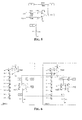
An adder HB25, which may be as detailed in Figure 4, sums these components
with a certain scale factor that depends only on the number n of qubits (which is
0.25 for n=3), generating a signal SQ representing the sum of the odd (or even)
components of the entanglement vector. The reference voltage of this adder is
2.5V, such to make the voltage signal representing the scaled sum SQ range
between [0÷5]Volts, which is the voltage range of the signals in the digital Part II
of the quantum gate.
The hardware structure of such a quantum gate must be designed for a pre-established
number n of qubits and it is usable for handling vectors having a
different number of qubits. In fact the adder of Figure 4 is specifically designed
for a certain number n of qubits (in the considered example n=3).
This lack of flexibility is overcome by realizing a quantum gate composed of a
plurality of interconnected modules.
Each module comprises an adder HB25 having a voltage buffer with an
operational amplifier, and the amplifiers of the voltage buffers of all modules are
connected in parallel. Basically each voltage buffer is composed of an operational
amplifier, a resistor coupling an input of the amplifier to a node at a voltage to be
summed and scaled, and a feedback resistor connected between an input and an
output of the amplifier.
A sample embodiment of such a voltage buffer is that of Figure 5. The resistors
may have different values from that of Figure 5, provided that the circuit operates
as a stand-alone buffer and constitutes a part of a modular adder when the
terminals of the amplifier are connected with corresponding terminals of other
alike buffers.
Preferably, the resistors have a relatively high resistance in order to prevent the
parallel of the resistors of all the buffers to have an excessively small value such
that the operational amplifier will not function correctly.
As it will be evident to the skilled person, different architectures of the voltage
buffer are possible, provided that they have an operational amplifier, a feedback
resistor and another resistor for coupling an input of the amplifier to a node at a
voltage to be summed.
Preferably, the adder HB25 of each module is composed of an auxiliary adder, as
that of Fig. 4, for generating a partial weighted sum SQMX with a certain scale
factor 1/2 m -1 of a certain number of components 2 m of even or odd components of
an entanglement vector, and a voltage buffer, as that depicted in Figure 5, input
with the voltage signal representative of the weighted sum SQMX. This
configuration is particularly convenient, because it allows to generate a weighted
sum SQ of 2 m + k components, by connecting 2 k modules in parallel.
Figure 6 dhows how two adders HB25 for n=3 qubits may be connected to realize
a section I-b suitable for the case of n=4 qubits.
Finally, an array of adders I-c (see Figure 3) generates the signals A1, ..., A8
representative of the odd (or even) components of an output vector, by subtracting
the components Q1, ..., Q8 from the scaled sum SQ.
For example, the adders of section I-c may be realized for example as depicted in
Figure 7.
A basic scheme of a module of a quantum gate of this invention is depicted in the
dashed rectangle of Fig. 8.
Each module substantially comprises an adder HB25 generating the signal SQ,
that can be coupled with the adders of the other modules by connecting in
common the pins W, U and S, an array of adders HB16, ..., HB23 generating
components of an interference vector A, a digital circuit LOGIC and an inverting
circuit INVERT.
Preferably, each module comprises also a subgroup HB13 of the aforementioned
array of multiplexers I-a of the entanglement subsystem. The logic command
signals Vc1 ..., Vc8, encoding the values of the binary function f(.) to be
processed with the Grover's algorithm, are sent to each subgroup of multiplexers
HB13 of the modules through the internal bus BUS.
The digital circuit LOGIC, belonging to the digital Part II of the quantum gate of
this invention, generates odd (or even) components of an output vector IN from
the respective components of the interference vector A and communicates through
the internal bus BUS with a microprocessor unit CPLD.
In order to better understand the functioning of the digital circuit LOGIC, let us
refer to the more detailed diagram of Fig. 9.
The circuit LOGIC comprises an identification circuit SELECTOR that generates a
relative identification bit string R and a comparator COMP that compares the
strings M and R. When the two strings are equal, the comparator switches active
the flag ENABLE, indicating that the microprocessor unit CPLD has selected the
module for exchanging data with it through the internal bus BUS.
The microprocessor unit CPLD performs different types of operations (storing
values, evaluating entropy and stopping iteration) in executing a Grover's
algorithm. For evaluating the entropy S of the interference vector A, the
microprocessor unit CPLD switches active a first logic signal OUT_EN, thus
allowing the A/D converter of the selected module to generate a digital string DA
representative of the components of output vector A, calculated by the selected
module.
An analog/digital converter, which for example may be the commercial device
ADC0808 of National Semiconductor, receives signals representing the
components A1, ..., A8 of the output vector A and produces a corresponding
binary string DA. The microprocessor unit that may be for example the
commercial device XC95288XL of Xilinx, receives this string and calculates the
Shannon entropy. If the Shannon entropy is greater than a pre-established value S,
the microprocessor CLPD commands a new iteration of the Grover's algorithm by
providing a second logic signal WR that makes the D/A converter generate the
analog signals IN, representing components of the last calculated interference
vector, from the digital string DIN output by the microprocessor CPLD.
The inverting circuit INVERT of Fig. 8 is depicted in detail in Fig. 10.
Substantially, it is composed of an array of inverters HB3, ..., HB10, which may
be realized as shown in Figure 11, that generates all the components O11, ..., 082
of a new superposition vector to be processed from the odd components IN1, ...,
IN8.
Basically, the microprocessor unit performs the following functions:
A display may also be connected to the CPLD for displaying results. If the
Shannon entropy is not sufficiently small, the binary string has to be re-converted
in an analog signal by a digital/analog converter in order to feed it back into the
entanglement subsystem I-a. In the embodiment of Figure 8, the digital/analog
converter was the commercial device AD7228 of Analog Devices.