EP1382982A1 - Heating compensated optical device - Google Patents
Heating compensated optical device Download PDFInfo
- Publication number
- EP1382982A1 EP1382982A1 EP02015037A EP02015037A EP1382982A1 EP 1382982 A1 EP1382982 A1 EP 1382982A1 EP 02015037 A EP02015037 A EP 02015037A EP 02015037 A EP02015037 A EP 02015037A EP 1382982 A1 EP1382982 A1 EP 1382982A1
- Authority
- EP
- European Patent Office
- Prior art keywords
- optical device
- supporting element
- partly
- optical
- light beam
- Prior art date
- Legal status (The legal status is an assumption and is not a legal conclusion. Google has not performed a legal analysis and makes no representation as to the accuracy of the status listed.)
- Granted
Links
- 230000003287 optical effect Effects 0.000 title claims abstract description 54
- 238000010438 heat treatment Methods 0.000 title claims description 8
- 239000000463 material Substances 0.000 claims abstract description 12
- 230000003595 spectral effect Effects 0.000 claims abstract description 6
- 230000002238 attenuated effect Effects 0.000 claims abstract description 4
- 230000005540 biological transmission Effects 0.000 claims abstract description 4
- 238000001816 cooling Methods 0.000 claims description 15
- 239000000835 fiber Substances 0.000 claims description 7
- 238000013507 mapping Methods 0.000 claims description 4
- 230000003247 decreasing effect Effects 0.000 claims description 2
- 238000010521 absorption reaction Methods 0.000 claims 1
- 230000017525 heat dissipation Effects 0.000 abstract description 3
- VYPSYNLAJGMNEJ-UHFFFAOYSA-N Silicium dioxide Chemical compound O=[Si]=O VYPSYNLAJGMNEJ-UHFFFAOYSA-N 0.000 description 12
- 229910052681 coesite Inorganic materials 0.000 description 5
- 229910052906 cristobalite Inorganic materials 0.000 description 5
- 239000000377 silicon dioxide Substances 0.000 description 5
- 229910052682 stishovite Inorganic materials 0.000 description 5
- 229910052905 tridymite Inorganic materials 0.000 description 5
- XUIMIQQOPSSXEZ-UHFFFAOYSA-N Silicon Chemical compound [Si] XUIMIQQOPSSXEZ-UHFFFAOYSA-N 0.000 description 2
- 239000004411 aluminium Substances 0.000 description 2
- 229910052782 aluminium Inorganic materials 0.000 description 2
- XAGFODPZIPBFFR-UHFFFAOYSA-N aluminium Chemical compound [Al] XAGFODPZIPBFFR-UHFFFAOYSA-N 0.000 description 2
- 229910052751 metal Inorganic materials 0.000 description 2
- 239000002184 metal Substances 0.000 description 2
- 238000012986 modification Methods 0.000 description 2
- 230000004048 modification Effects 0.000 description 2
- 229910052574 oxide ceramic Inorganic materials 0.000 description 2
- 239000011224 oxide ceramic Substances 0.000 description 2
- 229910052594 sapphire Inorganic materials 0.000 description 2
- 239000010980 sapphire Substances 0.000 description 2
- ZAMOUSCENKQFHK-UHFFFAOYSA-N Chlorine atom Chemical compound [Cl] ZAMOUSCENKQFHK-UHFFFAOYSA-N 0.000 description 1
- 239000011358 absorbing material Substances 0.000 description 1
- 239000000956 alloy Substances 0.000 description 1
- 229910045601 alloy Inorganic materials 0.000 description 1
- 150000001804 chlorine Chemical class 0.000 description 1
- 229910052801 chlorine Inorganic materials 0.000 description 1
- 239000000460 chlorine Substances 0.000 description 1
- 239000011248 coating agent Substances 0.000 description 1
- 238000000576 coating method Methods 0.000 description 1
- 239000013078 crystal Substances 0.000 description 1
- 230000001419 dependent effect Effects 0.000 description 1
- 230000009969 flowable effect Effects 0.000 description 1
- 125000001153 fluoro group Chemical class F* 0.000 description 1
- 238000013021 overheating Methods 0.000 description 1
- 239000000758 substrate Substances 0.000 description 1
Images
Classifications
-
- G—PHYSICS
- G02—OPTICS
- G02B—OPTICAL ELEMENTS, SYSTEMS OR APPARATUS
- G02B5/00—Optical elements other than lenses
- G02B5/20—Filters
- G02B5/205—Neutral density filters
-
- G—PHYSICS
- G02—OPTICS
- G02B—OPTICAL ELEMENTS, SYSTEMS OR APPARATUS
- G02B6/00—Light guides; Structural details of arrangements comprising light guides and other optical elements, e.g. couplings
- G02B6/24—Coupling light guides
- G02B6/26—Optical coupling means
- G02B6/264—Optical coupling means with optical elements between opposed fibre ends which perform a function other than beam splitting
- G02B6/266—Optical coupling means with optical elements between opposed fibre ends which perform a function other than beam splitting the optical element being an attenuator
Definitions
- the invention relates to an optical device dissipating heat.
- Optical devices comprising a supporting element and a partly absorbing element, which is attached on supporting element, are often used e. g. for attenuating the intensity of a light beam.
- An optical attenuator of the mentioned kind is known from the US-A 5,325,459. This attenuator comprises a supporting element coated with a metallic partly absorbing coating.
- the supporting element is provided with a quartz glass (e. g. BK7 available form the company Schott).
- the optical device comprises a supporting element providing a compensation to a local heating in the at least partly absorbing element. Therefore, the maximum temperature caused by partly absorbing the light beam will be reduced. Thus, leads to use the optical device for high power application. Furthermore, damages due to a local heating will be eliminated.
- the run of the temperature curve with respect to a cross section of the supporting element is like a Gaussian distribution with a distinct maximum
- the run of the temperature curve in the inventive supporting element is in a small temperature range without any reasonable maximum.
- the heating of the supporting element is almost uniform. Therefore the temperature gradient between the supporting element and the absorbing element is low.
- the supporting element is made of a crystalline structure, which enables dissipating a large amount of energy.
- the crystalline structure is provided with at least one orientation in the space having a preferred thermal conductivity for detaching the large amount of energy.
- the supporting element is preferably made of mono- or polycrystalline materials such as SiO 2 , modifications of SiO 2 , sapphire, silicium, oxide ceramics as well as chlorine or fluorine salt crystals. All those materials have at least one crystal-line structure also having a high thermal conductivity.
- the heat dissipation of the supporting element will be increased by providing a supporting element with a material having a thermal conductivity ⁇ larger than 2 W/mK.
- a supporting element is made of amorphous material (e. g. quartz glass) having a maximum thermal conductivity of about 1,5 W/mK, the increase of heat dissipation will be enabled.
- the expansion of the supporting element due to the heat is equal or at least partly adapted to the expansion of the absorbing element caused by the absorbed heat. Therefore, the interfacial tension is minimized and the thermal conduction between the absorbing element and the supporting element remain nearly without tension in between.
- the supporting element is made of a material having a high thermal conductivity and a high transmission, in a spectral range of the light beam between 1.2 to 1.7 ⁇ m. Due to this combination of the characteristics the local temperature of the impinging zone will be reduced reciprocal proportional to the thermal conductivity. Thus, a uniform temperature distribution in the optical device will be achieved.
- the supporting element and the absorbing element are substantially independent to the wavelength of an optical signal and therefore useably in a broad field.
- the partly absorbing element comprises at least one layer preferably a metal layer coated on the supporting element with varying or constant thickness.
- Preferable are combined materials of the supporting element and absorbing element having characteristics which assist each other and enable dissipating a large amount of energy.
- the supporting element and the at least partly absorbing element are both positioned preferably identical in position to an optical axis of the elements to optimise the attenuation. Therefore the optical properties are independent or nearly without any influence from the state of polarisation of the incident beam.
- a mapping element is preferably provided on at least one side of the supporting element and at least the partly absorbing element. This enables, for example, if provided on the side of the input beam and the output beam with respect to the optical device to map in a desired way the input beam to the supporting element and the output beam to the output fibre or a transmittive element.
- At least the supporting element is cooled by a cooling device to reduce the temperature of the absorbed energy.
- the cooling device can be solely or additionally provided with a supporting element having a crystalline structure or a structure with a thermal conductivity of at least 2 W/mK. Due to the cooling device which can act actively or passively the dissipation of heat can be increased.
- the cooling device comprises different components as heat pipes, cooling rips, blow nozzles for cooled air or Peltier-coolers, which can be provided in single use or in any combination with respect to the application of the optical device.
- the optical device in any of the inventive embodiments can be, for example, an optical attenuator. Further the optical device can be provided with an at least partly transmitting supporting element and a at least partly reflecting or attenuating absorbing element for the impinging light beam.
- an optical attenuator 11 can be coupled between an emitting source 12, e. g. an input fibre and an output fibre 13.
- a light beam 16 is emitted from the emitting source 12 and is directed to a disk 15 of the optical attenuator 11.
- a first lens 21 or a lens system between the emitting source 12 and the disk 15 to convert the light beam 16 into a parallel light.
- a second lens 25 or a lens system with range to collect the attenuated portion of the light beam 16 is preferably provided and focuses the collected portion as an output beam 19 into the output fibre 13.
- the disk 15 comprises a supporting element 17 having a rectangular cross section and a partly absorbing element 23. At least one side of the disc 15 is coated or evaporated with the at least partly absorbing element 23.
- the at least partly absorbing element 23 comprises preferably at least one metal layer.
- the at least partly absorbing element 23 can be determined with a constant thickness or with increasing, decreasing and/or varying thickness in different directions.
- the shown disc 15 comprising the supporting element 17 and partly absorbing element 21 is not limited to this shape and is described with respect to different shapes and further possibilities for providing the thickness of the partly absorbing material more in detail in the US-A 5,325,459, to which is hereby referred to. It is further understood, that the shape and the cross sections of the partly absorbing element 23 and the supporting element 17 is not limited to the described embodiments.
- the optical device 11 for attenuating the light beams 16 in the spectral range between 1.2 to 1.7 ⁇ m comprises a supporting element 17 made of sapphire which has substantially uniform attenuation over the spectral range.
- the refractive index is approximately 1.74 at the respective wavelength and the thermal conductivity is approximately 25 W/mK.
- the present invention achieves reducing the local overtemperature to below 20 K.
- a further embodiment of the invention is the choice of mono- or polycrystalline structure such as SiO 2 , modifications of SiO 2 , oxide ceramics and chlorine salts and fluor salts.
- the refractive index of SiO 2 is 1.53 at the range of the desired wavelength.
- the thermal conductivity is in the range between 6.8 to 11.3 W/mK.
- the properties of the supporting element 17 made of mono- or polycrystalline structures as silicium or similar substrate has e. g. a refractive index 3,48 and the thermal conductivity in the range of 159 W/mK.
- the common characteristic of the preferred supporting element 17 is thermal conductivity of at least 2W/mK and preferably a high rate of transmission, at least in the spectral range between 1.2 to 1.7 ⁇ m.
- a cooling device 29 can be attached to the optical element 15.
- the cooling device 29 is in direct contact at least with the supporting element 17.
- the cooling device 29 may partly or totally surrounding the optical device 15.
- the cooling device is preferably made of a material with a high thermal conductivity as e. g. aluminium or aluminium based alloy.
- the cooling device 29 may be additionally cooled with a flowable medium as e. g. air.
Landscapes
- Physics & Mathematics (AREA)
- General Physics & Mathematics (AREA)
- Optics & Photonics (AREA)
- Optical Modulation, Optical Deflection, Nonlinear Optics, Optical Demodulation, Optical Logic Elements (AREA)
- Optical Couplings Of Light Guides (AREA)
Abstract
Description
- The invention relates to an optical device dissipating heat.
- Optical devices comprising a supporting element and a partly absorbing element, which is attached on supporting element, are often used e. g. for attenuating the intensity of a light beam. An optical attenuator of the mentioned kind is known from the US-A 5,325,459. This attenuator comprises a supporting element coated with a metallic partly absorbing coating. The supporting element is provided with a quartz glass (e. g. BK7 available form the company Schott).
- When attenuating intensity of a light beam a large amount of energy might have to be dissipated at least out of the zone impinged by the light beam. Local heating would cause remaining deflection, changes of the optical properties or damages at least to the partly absorbing element.
- It is an object of the invention to provide an improved optical device subject to local heating. This object is solved by the independent claims and preferred embodiments are shown by the dependent claims.
- According to the invention, the optical device comprises a supporting element providing a compensation to a local heating in the at least partly absorbing element. Therefore, the maximum temperature caused by partly absorbing the light beam will be reduced. Thus, leads to use the optical device for high power application. Furthermore, damages due to a local heating will be eliminated.
- Different to prior art, wherein the run of the temperature curve with respect to a cross section of the supporting element is like a Gaussian distribution with a distinct maximum, the run of the temperature curve in the inventive supporting element is in a small temperature range without any reasonable maximum. The heating of the supporting element is almost uniform. Therefore the temperature gradient between the supporting element and the absorbing element is low.
- In a preferred embodiment of the invention the supporting element is made of a crystalline structure, which enables dissipating a large amount of energy. The crystalline structure is provided with at least one orientation in the space having a preferred thermal conductivity for detaching the large amount of energy. Thus, the local heating at least in the zone of the optical device impinged by the optical light beam will be reduced.
- For example, the supporting element is preferably made of mono- or polycrystalline materials such as SiO2, modifications of SiO2, sapphire, silicium, oxide ceramics as well as chlorine or fluorine salt crystals. All those materials have at least one crystal-line structure also having a high thermal conductivity.
- In a preferred embodiment or according to the invention the heat dissipation of the supporting element will be increased by providing a supporting element with a material having a thermal conductivity λ larger than 2 W/mK. Different to the optical device of the prior art, wherein the supporting element is made of amorphous material (e. g. quartz glass) having a maximum thermal conductivity of about 1,5 W/mK, the increase of heat dissipation will be enabled.
- Further to a preferred embodiment the expansion of the supporting element due to the heat is equal or at least partly adapted to the expansion of the absorbing element caused by the absorbed heat. Therefore, the interfacial tension is minimized and the thermal conduction between the absorbing element and the supporting element remain nearly without tension in between.
- In a further embodiment the supporting element is made of a material having a high thermal conductivity and a high transmission, in a spectral range of the light beam between 1.2 to 1.7 µm. Due to this combination of the characteristics the local temperature of the impinging zone will be reduced reciprocal proportional to the thermal conductivity. Thus, a uniform temperature distribution in the optical device will be achieved.
- In a further preferred embodiment the supporting element and the absorbing element are substantially independent to the wavelength of an optical signal and therefore useably in a broad field.
- In an other preferred embodiment the partly absorbing element comprises at least one layer preferably a metal layer coated on the supporting element with varying or constant thickness. Preferable are combined materials of the supporting element and absorbing element having characteristics which assist each other and enable dissipating a large amount of energy.
- In a preferred embodiment the supporting element and the at least partly absorbing element are both positioned preferably identical in position to an optical axis of the elements to optimise the attenuation. Therefore the optical properties are independent or nearly without any influence from the state of polarisation of the incident beam.
- A mapping element is preferably provided on at least one side of the supporting element and at least the partly absorbing element. This enables, for example, if provided on the side of the input beam and the output beam with respect to the optical device to map in a desired way the input beam to the supporting element and the output beam to the output fibre or a transmittive element.
- Further according to a preferred embodiment or according to the invention at least the supporting element is cooled by a cooling device to reduce the temperature of the absorbed energy. The cooling device can be solely or additionally provided with a supporting element having a crystalline structure or a structure with a thermal conductivity of at least 2 W/mK. Due to the cooling device which can act actively or passively the dissipation of heat can be increased.
- According to a preferred embodiment the cooling device comprises different components as heat pipes, cooling rips, blow nozzles for cooled air or Peltier-coolers, which can be provided in single use or in any combination with respect to the application of the optical device.
- The optical device in any of the inventive embodiments can be, for example, an optical attenuator. Further the optical device can be provided with an at least partly transmitting supporting element and a at least partly reflecting or attenuating absorbing element for the impinging light beam.
- Other objects and many of the attendant advantages of the present invention will be readily appreciated and become better understood by reference to the following detailed description when considered in connection with the accompanied drawing. Features, that are substantially or functionally equal or similar will be preferred to the same reference sign.
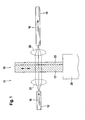
- Figure 1
- shows a schematic view of a preferred embodiment of an optical device according to the present invention.
- The invention shall now be illustrated with respect to the preferred embodiment of an optical attenuator. However, it is clear, that the principals of the invention can be applied to further optical devices and is not limited to attenuating devices.
- In Figure 1 an
optical attenuator 11 can be coupled between anemitting source 12, e. g. an input fibre and anoutput fibre 13. Alight beam 16 is emitted from theemitting source 12 and is directed to adisk 15 of theoptical attenuator 11. Preferably is provided afirst lens 21 or a lens system between theemitting source 12 and thedisk 15 to convert thelight beam 16 into a parallel light. Asecond lens 25 or a lens system with range to collect the attenuated portion of thelight beam 16 is preferably provided and focuses the collected portion as anoutput beam 19 into theoutput fibre 13. - The
disk 15 comprises a supportingelement 17 having a rectangular cross section and a partly absorbingelement 23. At least one side of thedisc 15 is coated or evaporated with the at least partly absorbingelement 23. The at least partly absorbingelement 23 comprises preferably at least one metal layer. The at least partly absorbingelement 23 can be determined with a constant thickness or with increasing, decreasing and/or varying thickness in different directions. - The shown
disc 15 comprising the supportingelement 17 and partly absorbingelement 21 is not limited to this shape and is described with respect to different shapes and further possibilities for providing the thickness of the partly absorbing material more in detail in the US-A 5,325,459, to which is hereby referred to. It is further understood, that the shape and the cross sections of the partly absorbingelement 23 and the supportingelement 17 is not limited to the described embodiments. - According to an exemplary embodiment of the invention the
optical device 11 for attenuating thelight beams 16 in the spectral range between 1.2 to 1.7 µm comprises a supportingelement 17 made of sapphire which has substantially uniform attenuation over the spectral range. The refractive index is approximately 1.74 at the respective wavelength and the thermal conductivity is approximately 25 W/mK. Different to prior art, where in the light beam with a power of 2 Watt causes a local overtemperature of 300 K, the present invention achieves reducing the local overtemperature to below 20 K. Thus, changes of the optical properties of the filter will be minimized as well as damaging or destroying the supporting and absorbingelement - A further embodiment of the invention is the choice of mono- or polycrystalline structure such as SiO2, modifications of SiO2, oxide ceramics and chlorine salts and fluor salts. For example, the refractive index of SiO2 is 1.53 at the range of the desired wavelength. The thermal conductivity is in the range between 6.8 to 11.3 W/mK. The properties of the supporting
element 17 made of mono- or polycrystalline structures as silicium or similar substrate has e. g. a refractive index 3,48 and the thermal conductivity in the range of 159 W/mK. - The common characteristic of the preferred supporting
element 17 is thermal conductivity of at least 2W/mK and preferably a high rate of transmission, at least in the spectral range between 1.2 to 1.7 µm. - A cooling
device 29 can be attached to theoptical element 15. Thecooling device 29 is in direct contact at least with the supportingelement 17. Thecooling device 29 may partly or totally surrounding theoptical device 15. According to one embodiment the cooling device is preferably made of a material with a high thermal conductivity as e. g. aluminium or aluminium based alloy. Thecooling device 29 may be additionally cooled with a flowable medium as e. g. air.
Claims (15)
- An optical device comprising:a structure with a supporting element (17) for supporting at least on one side of the supporting element (17) an at least partly absorbing element (23),wherein the at least partly absorbing element (23) is adapted to receive an optical signal andthe supporting element (17) is adapted to provide a compensation to a local heating in the at least partly absorbing element (23) resulting from absorption of the optical signal resulting.
- The optical device of claim 1, wherein the supporting element (17) is provided with a material having a crystalline structure, preferably having a monocrystal-or polycrystalline structure.
- The optical device of claim 1 or any one of the above claims, wherein the supporting element (17) is provided with a material having a thermal conductivity of at least 2 W/mK.
- The optical device of claim 1 or any one of the above claims, wherein the expansion due to heat of the at least partly supporting element (17) is equal or almost equal to that of the absorbing element (23).
- The optical device of claim 1 or any one of the above claims, wherein the supporting element (17) is made of a material having a high thermal conductivity and a high transmission in the spectral range between the wave length of 1.2 to 1.7 µm.
- The optical device of claim 1 or any one of the above claims, wherein the supporting element (17) and the absorbing element (23) are substantially independent from the wavelength of an optical signal.
- The optical device of claim 1 or any one of the above claims, wherein the at least partly absorbing element (23) comprises at least one layer coated or evaporated on the supporting element (17) with constant, with an increasing, decreasing or varying thickness.
- The optical device of claim 1 or any one of the above claims, wherein the supporting element (17) is provided with a transmittive material and the absorbing element (23) is adapted for attenuating, reflecting or partly reflecting the light beam (16).
- The optical device of claim 1 or any one of the above claims, wherein the optical axis of the supporting element (17) or the at least partly absorbing element (23) or both are identical positioned to an optical axis of the impinging beam.
- The optical device according to claim 1 or any of the above claims, further comprising at least one mapping element arranged for mapping the emitted light beam to the supporting element and the at least partly absorbing element or the output light beam form the supporting element and the at least partly absorbing element to a transmittive element or for mapping the input and output light beam to and from the supporting element and the at least partly absorbing element.
- The optical device according to claim 1 or any of the above claims, wherein the emitted light beam is emitted from an optical input fiber or the attenuated light beam is at least partly coupled into an output fiber or the emitted light beam is at least partly coupled into an output fiber.
- The optical device of claim 1 or any one of the above claims, further comprising a cooling device (29) adapted for cooling the at least partly absorbing element (23) and/or the supporting element (17).
- The optical device of claim 12, wherein the cooling device (19) comprises at least one of: cooling rips, heat pipes, slow nozzles for cooled air, or Peltier coolers.
- The optical device of claim 12, wherein the cooling device (29) is actively or passively cooled.
- The optical device of claim 1 or any one of the above claims being an attenuating device for attenuating the optical power of the light beam (16).
Priority Applications (3)
| Application Number | Priority Date | Filing Date | Title |
|---|---|---|---|
| EP02015037A EP1382982B1 (en) | 2002-07-05 | 2002-07-05 | Heating compensated optical device |
| DE60201527T DE60201527T2 (en) | 2002-07-05 | 2002-07-05 | Heat-compensated optical device |
| US10/455,890 US6950595B2 (en) | 2002-07-05 | 2003-06-06 | Optical attenuator with heat compensation |
Applications Claiming Priority (1)
| Application Number | Priority Date | Filing Date | Title |
|---|---|---|---|
| EP02015037A EP1382982B1 (en) | 2002-07-05 | 2002-07-05 | Heating compensated optical device |
Publications (2)
| Publication Number | Publication Date |
|---|---|
| EP1382982A1 true EP1382982A1 (en) | 2004-01-21 |
| EP1382982B1 EP1382982B1 (en) | 2004-10-06 |
Family
ID=29762611
Family Applications (1)
| Application Number | Title | Priority Date | Filing Date |
|---|---|---|---|
| EP02015037A Expired - Lifetime EP1382982B1 (en) | 2002-07-05 | 2002-07-05 | Heating compensated optical device |
Country Status (3)
| Country | Link |
|---|---|
| US (1) | US6950595B2 (en) |
| EP (1) | EP1382982B1 (en) |
| DE (1) | DE60201527T2 (en) |
Families Citing this family (1)
| Publication number | Priority date | Publication date | Assignee | Title |
|---|---|---|---|---|
| US20220317349A1 (en) * | 2019-08-14 | 2022-10-06 | Nippon Telegraph And Telephone Corporation | Mode Equalization Filter |
Citations (10)
| Publication number | Priority date | Publication date | Assignee | Title |
|---|---|---|---|---|
| EP0165015A2 (en) * | 1984-06-06 | 1985-12-18 | Nec Corporation | Light attenuation element |
| JPS61133682A (en) * | 1984-12-03 | 1986-06-20 | Mitsubishi Electric Corp | Laser light attenuator |
| US5325459A (en) * | 1992-02-25 | 1994-06-28 | Hewlett-Packard Company | Optical attenuator used with optical fibers and compensation means |
| US5335245A (en) * | 1992-03-02 | 1994-08-02 | L'air Liquide, Societe Anonyme Pour L'etude Et L'exploitation Des Procedes Georges Claude | Power laser with uncoated diamond window |
| JPH0829252A (en) * | 1994-07-19 | 1996-02-02 | Miyachi Technos Corp | Laser output detector |
| JPH08201604A (en) * | 1995-01-31 | 1996-08-09 | Nippondenso Co Ltd | Laser light attenuator |
| US5726797A (en) * | 1995-07-25 | 1998-03-10 | The United States Of America As Represented By The Secretary Of Commerce | Infrared neutral-density filter having copper alloy film |
| JPH10101486A (en) * | 1996-09-30 | 1998-04-21 | Mitsubishi Materials Corp | Optical materials for ultraviolet laser light |
| EP0921419A1 (en) * | 1997-12-08 | 1999-06-09 | Commissariat A L'energie Atomique | Light absorbant coating with high absorption |
| EP0994370A2 (en) * | 1998-10-05 | 2000-04-19 | Lucent Technologies Inc. | Optical attenuator structure and method using polymer material |
Family Cites Families (6)
| Publication number | Priority date | Publication date | Assignee | Title |
|---|---|---|---|---|
| US3746429A (en) * | 1971-08-05 | 1973-07-17 | Recognition Systems | Linear variable light attenuator |
| US5144498A (en) * | 1990-02-14 | 1992-09-01 | Hewlett-Packard Company | Variable wavelength light filter and sensor system |
| CA2199996C (en) * | 1997-03-14 | 2002-08-13 | Cindy Xing Qiu | Methods to fabricate dense wavelength division multiplexers |
| US6102715A (en) * | 1998-02-10 | 2000-08-15 | The Great American Gumball Corporation | Personal computer peripheral device adapter |
| US6778337B2 (en) * | 2000-12-12 | 2004-08-17 | The Furukawa Electric Co., Ltd. | Optical attenuator and optical attenuator module |
| JP2002323662A (en) * | 2001-04-24 | 2002-11-08 | Furukawa Electric Co Ltd:The | Optical filter angle adjusting device, angle adjusting method, and optical module |
-
2002
- 2002-07-05 EP EP02015037A patent/EP1382982B1/en not_active Expired - Lifetime
- 2002-07-05 DE DE60201527T patent/DE60201527T2/en not_active Expired - Fee Related
-
2003
- 2003-06-06 US US10/455,890 patent/US6950595B2/en not_active Expired - Fee Related
Patent Citations (10)
| Publication number | Priority date | Publication date | Assignee | Title |
|---|---|---|---|---|
| EP0165015A2 (en) * | 1984-06-06 | 1985-12-18 | Nec Corporation | Light attenuation element |
| JPS61133682A (en) * | 1984-12-03 | 1986-06-20 | Mitsubishi Electric Corp | Laser light attenuator |
| US5325459A (en) * | 1992-02-25 | 1994-06-28 | Hewlett-Packard Company | Optical attenuator used with optical fibers and compensation means |
| US5335245A (en) * | 1992-03-02 | 1994-08-02 | L'air Liquide, Societe Anonyme Pour L'etude Et L'exploitation Des Procedes Georges Claude | Power laser with uncoated diamond window |
| JPH0829252A (en) * | 1994-07-19 | 1996-02-02 | Miyachi Technos Corp | Laser output detector |
| JPH08201604A (en) * | 1995-01-31 | 1996-08-09 | Nippondenso Co Ltd | Laser light attenuator |
| US5726797A (en) * | 1995-07-25 | 1998-03-10 | The United States Of America As Represented By The Secretary Of Commerce | Infrared neutral-density filter having copper alloy film |
| JPH10101486A (en) * | 1996-09-30 | 1998-04-21 | Mitsubishi Materials Corp | Optical materials for ultraviolet laser light |
| EP0921419A1 (en) * | 1997-12-08 | 1999-06-09 | Commissariat A L'energie Atomique | Light absorbant coating with high absorption |
| EP0994370A2 (en) * | 1998-10-05 | 2000-04-19 | Lucent Technologies Inc. | Optical attenuator structure and method using polymer material |
Non-Patent Citations (4)
| Title |
|---|
| PATENT ABSTRACTS OF JAPAN vol. 010, no. 325 (E - 451) 6 November 1986 (1986-11-06) * |
| PATENT ABSTRACTS OF JAPAN vol. 1996, no. 06 28 June 1996 (1996-06-28) * |
| PATENT ABSTRACTS OF JAPAN vol. 1996, no. 12 26 December 1996 (1996-12-26) * |
| PATENT ABSTRACTS OF JAPAN vol. 1998, no. 09 31 July 1998 (1998-07-31) * |
Also Published As
| Publication number | Publication date |
|---|---|
| DE60201527D1 (en) | 2004-11-11 |
| US20040033046A1 (en) | 2004-02-19 |
| EP1382982B1 (en) | 2004-10-06 |
| US6950595B2 (en) | 2005-09-27 |
| DE60201527T2 (en) | 2006-02-02 |
Similar Documents
| Publication | Publication Date | Title |
|---|---|---|
| US6268956B1 (en) | End pumped zig-zag slab laser gain medium | |
| US9933605B2 (en) | Laser-pumped high-radiance incoherent light source | |
| US6256142B1 (en) | End pumped zig-zag slab laser gain medium | |
| US5317585A (en) | Laser reflecting cavity with ASE suppression and heat removal | |
| US6041610A (en) | Optical refrigerator using reflectivity tuned dielectric mirrors | |
| US6215580B1 (en) | Wavelength converter for generating optical harmonics of incident laser light at high efficiency and method for varying wavelength of incident laser light | |
| EP0422418A2 (en) | Integrating laser diode pumped laser apparatus | |
| US11914214B2 (en) | Reflective device | |
| US5335245A (en) | Power laser with uncoated diamond window | |
| US12435931B2 (en) | Radiative heatsink | |
| US7123634B2 (en) | Zig-zag laser amplifier with polarization controlled reflectors | |
| JPH04179180A (en) | Short wavelength laser light source | |
| US6944196B2 (en) | Solid state laser amplifier | |
| US9209588B2 (en) | Disk laser | |
| EP1382982B1 (en) | Heating compensated optical device | |
| US20240084997A1 (en) | Thermal light emitting device | |
| US20110235177A1 (en) | Athermal abirefringent optical components | |
| Godfried et al. | Use of CVD diamond in high-power CO2 lasers and laser diode arrays | |
| JP2007067123A (en) | Laser pulse compressor | |
| WO2021083437A1 (en) | A method and a device for heat removal from a flat nir-mir laser mirror | |
| JPH0728071B2 (en) | Solid-state laser device | |
| Petros et al. | High energy totally conductive cooled, diode pumped, 2μm laser | |
| JPH08179170A (en) | Semiconductor laser module with thermoelectric cooling element | |
| KR20240144166A (en) | Germanium AOD system with parallel and perpendicular orientations | |
| Siegmund | Coronagraphic and low-emissivity astronomical reflector (CLEAR): heat trap design |
Legal Events
| Date | Code | Title | Description |
|---|---|---|---|
| PUAI | Public reference made under article 153(3) epc to a published international application that has entered the european phase |
Free format text: ORIGINAL CODE: 0009012 |
|
| 17P | Request for examination filed |
Effective date: 20030411 |
|
| AK | Designated contracting states |
Kind code of ref document: A1 Designated state(s): AT BE BG CH CY CZ DE DK EE ES FI FR GB GR IE IT LI LU MC NL PT SE SK TR |
|
| AX | Request for extension of the european patent |
Extension state: AL LT LV MK RO SI |
|
| GRAP | Despatch of communication of intention to grant a patent |
Free format text: ORIGINAL CODE: EPIDOSNIGR1 |
|
| GRAS | Grant fee paid |
Free format text: ORIGINAL CODE: EPIDOSNIGR3 |
|
| GRAA | (expected) grant |
Free format text: ORIGINAL CODE: 0009210 |
|
| AK | Designated contracting states |
Kind code of ref document: B1 Designated state(s): DE FR GB |
|
| REG | Reference to a national code |
Ref country code: GB Ref legal event code: FG4D |
|
| AKX | Designation fees paid |
Designated state(s): DE FR GB |
|
| REF | Corresponds to: |
Ref document number: 60201527 Country of ref document: DE Date of ref document: 20041111 Kind code of ref document: P |
|
| PLBE | No opposition filed within time limit |
Free format text: ORIGINAL CODE: 0009261 |
|
| STAA | Information on the status of an ep patent application or granted ep patent |
Free format text: STATUS: NO OPPOSITION FILED WITHIN TIME LIMIT |
|
| ET | Fr: translation filed | ||
| 26N | No opposition filed |
Effective date: 20050707 |
|
| PGFP | Annual fee paid to national office [announced via postgrant information from national office to epo] |
Ref country code: FR Payment date: 20060717 Year of fee payment: 5 |
|
| PGFP | Annual fee paid to national office [announced via postgrant information from national office to epo] |
Ref country code: DE Payment date: 20070831 Year of fee payment: 6 |
|
| REG | Reference to a national code |
Ref country code: FR Ref legal event code: ST Effective date: 20080331 |
|
| PG25 | Lapsed in a contracting state [announced via postgrant information from national office to epo] |
Ref country code: FR Free format text: LAPSE BECAUSE OF NON-PAYMENT OF DUE FEES Effective date: 20070731 |
|
| PGFP | Annual fee paid to national office [announced via postgrant information from national office to epo] |
Ref country code: GB Payment date: 20080709 Year of fee payment: 7 |
|
| PG25 | Lapsed in a contracting state [announced via postgrant information from national office to epo] |
Ref country code: DE Free format text: LAPSE BECAUSE OF NON-PAYMENT OF DUE FEES Effective date: 20090203 |
|
| GBPC | Gb: european patent ceased through non-payment of renewal fee |
Effective date: 20090705 |
|
| PG25 | Lapsed in a contracting state [announced via postgrant information from national office to epo] |
Ref country code: GB Free format text: LAPSE BECAUSE OF NON-PAYMENT OF DUE FEES Effective date: 20090705 |