EP1382917A1 - Air conditioner - Google Patents
Air conditioner Download PDFInfo
- Publication number
- EP1382917A1 EP1382917A1 EP02702856A EP02702856A EP1382917A1 EP 1382917 A1 EP1382917 A1 EP 1382917A1 EP 02702856 A EP02702856 A EP 02702856A EP 02702856 A EP02702856 A EP 02702856A EP 1382917 A1 EP1382917 A1 EP 1382917A1
- Authority
- EP
- European Patent Office
- Prior art keywords
- heat exchanger
- air
- casing
- proximate
- centrifugal fan
- Prior art date
- Legal status (The legal status is an assumption and is not a legal conclusion. Google has not performed a legal analysis and makes no representation as to the accuracy of the status listed.)
- Withdrawn
Links
Images


Classifications
-
- F—MECHANICAL ENGINEERING; LIGHTING; HEATING; WEAPONS; BLASTING
- F24—HEATING; RANGES; VENTILATING
- F24F—AIR-CONDITIONING; AIR-HUMIDIFICATION; VENTILATION; USE OF AIR CURRENTS FOR SCREENING
- F24F1/00—Room units for air-conditioning, e.g. separate or self-contained units or units receiving primary air from a central station
- F24F1/0007—Indoor units, e.g. fan coil units
- F24F1/0018—Indoor units, e.g. fan coil units characterised by fans
- F24F1/0022—Centrifugal or radial fans
-
- F—MECHANICAL ENGINEERING; LIGHTING; HEATING; WEAPONS; BLASTING
- F24—HEATING; RANGES; VENTILATING
- F24F—AIR-CONDITIONING; AIR-HUMIDIFICATION; VENTILATION; USE OF AIR CURRENTS FOR SCREENING
- F24F1/00—Room units for air-conditioning, e.g. separate or self-contained units or units receiving primary air from a central station
- F24F1/0007—Indoor units, e.g. fan coil units
- F24F1/0035—Indoor units, e.g. fan coil units characterised by introduction of outside air to the room
-
- F—MECHANICAL ENGINEERING; LIGHTING; HEATING; WEAPONS; BLASTING
- F24—HEATING; RANGES; VENTILATING
- F24F—AIR-CONDITIONING; AIR-HUMIDIFICATION; VENTILATION; USE OF AIR CURRENTS FOR SCREENING
- F24F1/00—Room units for air-conditioning, e.g. separate or self-contained units or units receiving primary air from a central station
- F24F1/0007—Indoor units, e.g. fan coil units
- F24F1/0041—Indoor units, e.g. fan coil units characterised by exhaustion of inside air from the room
-
- F—MECHANICAL ENGINEERING; LIGHTING; HEATING; WEAPONS; BLASTING
- F24—HEATING; RANGES; VENTILATING
- F24F—AIR-CONDITIONING; AIR-HUMIDIFICATION; VENTILATION; USE OF AIR CURRENTS FOR SCREENING
- F24F1/00—Room units for air-conditioning, e.g. separate or self-contained units or units receiving primary air from a central station
- F24F1/0007—Indoor units, e.g. fan coil units
- F24F1/0043—Indoor units, e.g. fan coil units characterised by mounting arrangements
- F24F1/0047—Indoor units, e.g. fan coil units characterised by mounting arrangements mounted in the ceiling or at the ceiling
-
- F—MECHANICAL ENGINEERING; LIGHTING; HEATING; WEAPONS; BLASTING
- F24—HEATING; RANGES; VENTILATING
- F24F—AIR-CONDITIONING; AIR-HUMIDIFICATION; VENTILATION; USE OF AIR CURRENTS FOR SCREENING
- F24F1/00—Room units for air-conditioning, e.g. separate or self-contained units or units receiving primary air from a central station
- F24F1/0007—Indoor units, e.g. fan coil units
- F24F1/0059—Indoor units, e.g. fan coil units characterised by heat exchangers
- F24F1/0063—Indoor units, e.g. fan coil units characterised by heat exchangers by the mounting or arrangement of the heat exchangers
-
- F—MECHANICAL ENGINEERING; LIGHTING; HEATING; WEAPONS; BLASTING
- F24—HEATING; RANGES; VENTILATING
- F24F—AIR-CONDITIONING; AIR-HUMIDIFICATION; VENTILATION; USE OF AIR CURRENTS FOR SCREENING
- F24F1/00—Room units for air-conditioning, e.g. separate or self-contained units or units receiving primary air from a central station
- F24F1/0007—Indoor units, e.g. fan coil units
- F24F1/0059—Indoor units, e.g. fan coil units characterised by heat exchangers
- F24F1/0067—Indoor units, e.g. fan coil units characterised by heat exchangers by the shape of the heat exchangers or of parts thereof, e.g. of their fins
-
- F—MECHANICAL ENGINEERING; LIGHTING; HEATING; WEAPONS; BLASTING
- F24—HEATING; RANGES; VENTILATING
- F24F—AIR-CONDITIONING; AIR-HUMIDIFICATION; VENTILATION; USE OF AIR CURRENTS FOR SCREENING
- F24F13/00—Details common to, or for air-conditioning, air-humidification, ventilation or use of air currents for screening
- F24F13/02—Ducting arrangements
- F24F13/06—Outlets for directing or distributing air into rooms or spaces, e.g. ceiling air diffuser
- F24F2013/0616—Outlets that have intake openings
Definitions
- the present invention relates to an air conditioner, and more particularly relates to an air conditioner recessed in a ceiling.
- An air conditioner comprises an outdoor unit, which includes a compressor, a fan, and a heat exchanger, and which is installed outdoors; and an indoor unit, which includes a fan and a heat exchanger.
- Types of indoor units include a type attached to a wall, and a type recessed in a ceiling.
- the indoor unit of the ceiling-recessed type principally comprises a casing having an inlet and an outlet on the bottom side, a centrifugal fan disposed inside the casing, and a heat exchanger disposed between the centrifugal fan and the outlet.
- the indoor air is taken in from the inlet into the casing by the centrifugal fan. Further, the air taken in is blown in the horizontal direction.
- the air delivered from the centrifugal fan is heat exchanged in the heat exchanger, which is disposed so that it surrounds the centrifugal fan. Subsequently, that air is supplied from the outlet to the indoor space.
- the ventilation from the outlet of the air conditioner may become uneven because of the shape of the internal ventilation unit.
- a ceiling-recessed indoor unit is disposed in the ceiling, the size of the casing is limited, and a centrifugal fan and a heat exchanger are disposed in that limited casing space. Therefore, it is difficult to prevent the ventilation from becoming uneven. Further, if the ventilation becomes uneven, it leads to the generation of ventilation noise from the part where there is a strong airflow, and also leads to a reduction in cooling and heating performance.
- the object of the present invention is to provide a uniform wind speed distribution at the outlet of an indoor unit in an air conditioner having a centrifugal fan and in addition, to improve heat exchange efficiency without increasing the dimensions of the indoor unit.
- the air conditioner as recited in Claim 1 comprises a casing, a centrifugal fan, and a heat exchanger.
- the casing has an inlet for sucking in air to the inside, and outlets for blowing out air to the outside.
- the centrifugal fan is disposed in the interior of the casing.
- the heat exchanger is provided in the interior of the casing so that it surrounds the centrifugal fan.
- the heat exchanger is disposed so that, among air passageways extending from the centrifugal fan to the outlets via the heat exchanger, the air passageway that extends from the centrifugal fan to the outlet and that opposes the direction of the wind from the centrifugal fan is narrower than the other air passageway.
- a heat exchanger is disposed so that, among the air passageways, the air passageways extending from the centrifugal fan to the outlets opposing the direction of the wind are narrower compared with other air passageways. Consequently, the air resistance of these air passageways increases, the airflow speed is held down, and the speed distribution of the wind blown out from the outlets can be made uniform. Thereby, it is possible to control the ventilation noise as well as to maintain cooling and heating performance.
- the air conditioner according to Claim 2 is the air conditioner as recited in Claim 1, wherein the casing is rectangular shaped.
- the heat exchanger has first, second, and third proximate parts, respectively in the reverse order of the rotational direction of the centrifugal fan, that are more proximate to the sidewalls of the casing than both sides of each of the proximate parts.
- the length of a first portion of the heat exchanger between the first proximate part and the second proximate part is substantially the same as the length of a second portion between the second proximate part and the third proximate part.
- the volume of the air blown out from the outlets becomes even, and the volume of the air that flows through the first and second portions become substantially equal.
- the lengths of the heat exchanger in the first and second portions are substantially equal, the heat exchange efficiencies are substantially identical. Thereby, the heat exchange efficiencies in the air passageways become uniform, cooling and heating efficiencies are improved, and the temperature distribution of the air from the outlets becomes uniform.
- the air conditioner as recited in Claim 3 comprises a casing, a centrifugal fan, and a heat exchanger.
- the rectangular casing has an inlet for sucking in air to the inside, and outlets for blowing out air to the outside.
- the centrifugal fan is disposed in the interior of the casing.
- the heat exchanger is provided in the interior of the casing so that it surrounds the centrifugal fan.
- the heat exchanger has first, second, and third proximate parts, respectively in the reverse order of the rotational direction of the centrifugal fan, that are more proximate to the casing than both sides of each of the proximate parts.
- the first proximate part and the third proximate part of the heat exchanger are positioned in the vicinity of an axis, which passes through the center of the centrifugal fan and is orthogonal to opposing first and second sidewalls of the casing.
- a second proximate part of the heat exchanger is disposed so that it is offset on the first proximate part side of the heat exchanger with respect to an axis, which passes through the center of the centrifugal fan and is orthogonal to opposing third and fourth sidewalls of the casing.
- the outlets comprises first and second outlets provided respectively in the first and second sidewalls of the casing so that they interpose the first proximate part, and third and fourth outlets provided so that they interpose the third proximate part.
- the first outlet and the second outlet are disposed in a first sidewall of the casing so that they interpose a first proximate part.
- the downstream side of the rotational direction of the centrifugal fan is provisionally made the first outlet, and the upstream side is provisionally made the second outlet, then the wind direction of the centrifugal fan opposes the second outlet, which increases the air volume to the second outlet. Conversely, the air volume to the first outlet is smaller than the second outlet. This applies likewise for the third outlet and the fourth outlet.
- the heat exchanger is arranged inclined with respect to the axis that passes through the center of the centrifugal fan and that is orthogonal to the casing sidewall.
- the air resistance in the air passageway extending from the centrifugal fan to the outlets is adjusted so as to make the air volume from each of the outlets uniform.
- the air passageway formed between the first proximate part and the second proximate part is narrower than the air passageway formed between the third proximate part and the second proximate part. Because the narrowed air passageway creates an air resistance to the flow of air blown out from the centrifugal fan, the airflow that passes through the first proximate part and the second proximate part and is blown out from the second outlet is less than the other air passageways, and the speed distribution of the wind blown out from the outlets can be made uniform. Thereby, the ventilation noise can be controlled, and cooling and heating performance can also be maintained.
- the air conditioner as recited in Claim 4 is the air conditioner as recited in Claim 3, wherein the length of a first portion of the heat exchanger between the first proximate part and the second proximate part is substantially the same as the length of a second portion between the second proximate part and a third proximate part.
- the heat exchange efficiencies in the air passageways are substantially identical, the same as in Claim 2. Thereby, the heat exchange efficiencies in the air passageways are made uniform, the cooling and heating efficiencies are improved, and the temperature distribution of the air from each of the outlets is made uniform.
- the air conditioner as recited in Claim 5 is the air conditioner as recited in Claim 2 or Claim 4, wherein the heat exchanger comprises a bent part that is bent in the direction of the interior of the casing in the first portion.
- the second proximate part Because the position of the second proximate part is offset toward the first proximate part side, it is necessary to bend the second proximate part in order to make the length of the heat exchanger in the first and second portions equal. At this point, the heat exchanger in the first portion is bent in a direction toward the interior of the casing. Thereby, the lengths of the heat exchanger are equalized without the need to change the size of the casing, and the configuration is simplified.
- the air conditioner as recited in Claim 6 is the air conditioner as recited in any one claim of Claim 1 to Claim 5, wherein the heat exchanger comprises heat exchanger main bodies and a connecting part that connects the heat exchanger main bodies.
- the number of bending processes per heat exchanger can be reduced. Thereby, the frequency of heat exchanger defects can be controlled.
- the air conditioner as recited in Claim 7 comprises a casing, a centrifugal fan, a heat exchanger, and a coolant supply unit.
- the casing comprises an inlet for sucking in air to the inside, and outlets for blowing out air to the outside and which are disposed rectangularly.
- the centrifugal fan is disposed in the interior of the casing.
- the heat exchanger is provided in the interior of the casing so that it surrounds the centrifugal fan, and is disposed rectangularly on the inner side of the outlets.
- the coolant supply unit is provided at one comer of the heat exchanger, and supplies a coolant to the heat exchanger.
- the heat exchanger comprises an extension part on the downstream side of the rotational direction of the centrifugal fan with respect to the coolant supply unit.
- the heat exchanger is provided with an extension part with respect to the coolant supply unit on the downstream side of the rotational direction of the centrifugal fan.
- the air conditioner as recited in Claim 8 is the air conditioner as recited in Claim 7, wherein the extension part is bent in the direction of the interior of the casing.
- the extension part of the heat exchanger with respect to the coolant supply unit on the downstream side of the rotational direction of the centrifugal fan is a bent part that is bent in the direction toward the interior of the casing.
- FIG. 1 shows an exterior perspective view of the indoor unit 1 of the air conditioner according to the first embodiment of the present invention.
- FIG. 2 is a vertical cross-sectional view and
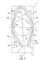
- FIG. 3 is a horizontal cross-sectional view of the indoor unit at a surface that includes the centrifugal fan.
- An indoor unit 1 is a ceiling-recessed type, and comprises a casing 11 that is recessed in a ceiling.
- a turbofan 40 centrifugal fan
- a heat exchanger 30 are provided in the casing 11.
- the indoor unit 1 takes in air placed in the indoor space, air conditions the air, and supplies that air to the indoor space after it has been air-conditioned by the heat exchanger.
- the casing 11 is a case that holds members of the indoor unit 1 therein.
- the casing 11 has an outline shape of a rectangular parallelepiped, and has a bottom plate 12 on the bottom thereof.
- An outlet 20 is formed on the outer side of the long side of the bottom plate 12, and an inlet 21 is provided on the inner side of the outlet 20.
- the outlet 20 is a ventilation port for supplying air that has been air-conditioned by the indoor unit 1 to the indoor space
- the inlet 21 is a ventilation port for taking in air from the indoor space to the indoor unit 1.
- the outlet 20 has a first outlet 20a provided on the downstream side (from the center of the long side) of the rotational direction of the turbofan 40; and a second outlet 20b provided on the upstream side of the rotational direction. Further, on the other long side, the outlet 20 has a third outlet 20c provided at a position opposing the second outlet 20b on the downstream side (from the center of the long side) of the rotational direction of turbofan 40; and a fourth outlet 20d provided at a position opposing the first outlet 20a on the upstream side of the rotational direction.
- the turbofan 40 is positioned substantially at the center of the casing 11.
- the turbofan 40 is provided with vanes at the periphery. By rotating in the direction of the arrow R in FIG. 3, pushes out the air in the interior of the turbofan 40 in the rotational direction, producing an airflow in the interior of the indoor unit 1.
- the heat exchanger 30 is a member that exchanges heat with the ventilating air. Further, the heat exchanger 30 is formed in a substantially rhombic shape so that it surrounds the turbofan 40, and has first, second, and third proximate parts 50a, 50b, and 50c that are proximate to the inner wall of the casing 11 more than both sides of each of the proximate parts 50a, 50b, 50c, respectively.
- the first proximate part 50a is positioned in the vicinity of an axis 14, which passes through the center of the turbofan 40 and is orthogonal to the long side of the casing 11, and is interposed between the first outlet 20a and the second outlet 20b.
- the third proximate part 50c is positioned on the opposite side opposing the first proximate part 50a, and is interposed between the third outlet 20c and the fourth outlet 20d.
- the second proximate part 50b is positioned on an axis 36, which is inclined toward the second outlet 20b side (the first proximate part 50a side) by just a predetermined angle from an axis 15, which passes through the center of the turbofan 40 and is orthogonal to the short side of the casing 11.
- the heat exchanger 30 is connected to a coolant supply unit 31 at the end part of the heat exchanger 30. Further, the coolant supply unit 31 is disposed on the fourth outlet 20d side displaced with respect to the axis 15.
- an air passageway is formed from the turbofan 40 to each of the outlets.
- a first air passageway 35a which extends from the turbofan 40 to the first outlet 20a, is formed between the coolant supply unit 31 and the first proximate part 50a.
- a second air passageway 35b which extends from the turbofan 40 to the second outlet 20b, is formed between the first proximate part 50a and the second proximate part 50b.
- a third air passageway 35c which extends from the turbofan 40 to the third outlet 20c, is formed between the second proximate part 50b and the third proximate part 50c.
- a fourth air passageway 35d which extends from the turbofan 40 to the fourth outlet 20d, is formed between the third proximate part 50c and the coolant supply unit 31.
- portions 30a - 30d of the heat exchanger 30 are disposed corresponding to the air passageways 35a - 35d, respectively.
- the first portion 30a is disposed in the first air passageway 35a between the coolant supply unit 31 and the first proximate part 50a
- the second portion 30b is disposed in the second air passageway 35b between the first proximate part 50a and the second proximate part 50b.
- the third portion 30c is disposed in the third air passageway 35c between the second proximate part 50b and the third proximate part 50c
- the fourth portion 30d is disposed in the fourth air passageway 35d between the third proximate part 50c and the coolant supply unit 31.
- the first portion 30a and third portion 30c are shorter than the second portion 30b and fourth the portion 30d.
- the interior of the indoor unit 1 is ventilated by the rotation of the turbofan 40. Air is taken into the interior of the indoor unit 1 from the inlet 21, which faces the indoor space. The air taken in is then delivered by the turbofan 40 to the surroundings thereof. The air that has been pushed out is heat exchanged by the heat exchanger 30, which is arranged at the circumference of the turbofan 40, and is then supplied from the outlets 20a - 20d to the indoor space.
- the following discusses the wind speed (airflow) of the air passageways 35a - 35d for the case in which the turbofan 40 has rotated.
- the second outlet 20b opposes the direction of the wind from the turbofan 40, and the wind speed of the air from the turbofan 40 increases if there is no heat exchanger 30.
- the third outlet 20c is arranged at a position along the direction of the wind from the turbofan 40, and does not oppose the direction of the wind from the turbofan 40.
- the third outlet 20c is disposed at a position at which the wind speed of the air from the turbofan 40 is slower if there is no heat exchanger 30.
- This is the same for the first outlet 20a and the fourth outlet 20d side of the axis 14. Namely, because of the rotational direction of the turbofan 40, and the arrangement of the outlets 20a, 20d, the wind speed of the air to the fourth outlet 20d is faster compared with the first air passageway 35a if there is no heat exchanger 30.
- the substantially rhombically formed heat exchanger 30 is disposed inclined with respect to the axis 15, and the widths (lengths) of the portions of the heat exchanger 30 in the air passageways 35a - 35d to the outlets 20a - 20d are not equal.
- the widths of the second and fourth portions 30b, 30d are narrower than the widths of the first and third portions 30a, 30c.
- the air resistance when passing through the second and fourth portions 30b, 30d is greater than when passing through the first and third portions 30a, 30c.
- the volume of air (wind speed) that passes through each of the air passageways 35a - 35d and that is blown out from the air outlets 20a - 20d, respectively, are made uniform.
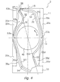
- FIG. 4 is a horizontal cross-sectional view of the indoor unit 2 of the air conditioner according to the second embodiment of the present invention.
- the air resistance of each air passageway varies due to the offset arrangement of the heat exchanger, and the present embodiment aims to make the air volume from the outlets uniform.
- the length (i.e., the heat exchange surface area) of each portion of the heat exchanger, wherein each portion is disposed in an air passageway differs. Accordingly, although the air volume from each outlet has been made uniform, there is a risk that the temperature distribution will become uneven.
- the second embodiment differs from the first embodiment only in the constitution of the heat exchanger; other constitutional aspects are the same.
- a heat exchanger main body 32 is a member that exchanges heat with the air that is ventilated, and is disposed so that it surrounds the turbofan 40, the same as mentioned earlier.
- the heat exchanger 32 comprises a first main body 321, which is disposed on the first and second outlets 20a, 20b side of the axis 15, which passes through the center of the turbofan 40 and is orthogonal to the short side of the casing 11; and a second main body 322, which is disposed on the third and fourth outlets 20c, 20d side, i.e., on the reverse side.
- first main body 321 and the second main body 322 are connected by a connecting member 55 at one end in the direction along the axis 15, and are connected by a coolant supply unit 33 at the other end. Furthermore, the coolant supply unit 33 is disposed so that it is shifted toward the fourth outlet 20d side of the axis 15.
- the heat exchanger 32 has first, second, and third proximate parts 53a, 53b and 53c that are more proximate to the inner wall of the casing 11 than both sides of each of the proximate parts 53a, 53b, 53c.
- the first proximate part 53a is positioned in the vicinity of the axis 14, and is interposed between the first outlet 20a and the second outlet 20b.
- the third proximate part 53c is positioned on the reverse side of and opposing the first proximate part 53a, and is interposed between the third outlet 20c and the fourth outlet 20d.
- the second proximate part 53b is positioned in the vicinity of the axis 37, which is inclined toward the second outlet 20b side of the axis 15 by a predetermined angle.
- the first air passageway 35a which extends from the turbofan 40 to the first outlet 20a, is formed between the coolant supply unit 33 and the first proximate part 53a.
- the second air passageway 35b which extends from the turbofan 40 to the second outlet 20b, is formed between the first proximate part 53a and the second proximate part 53b.
- the third air passageway 35c which extends from the turbofan 40 to the third outlet 20c, is formed between the second proximate part 53b and the third proximate part 53c.
- the fourth air passageway 35d which extends from the turbofan 40 to the fourth outlet 20d, is formed between the third proximate part 53c and the coolant supply unit 33.
- a first portion 32a is disposed in the first air passageway 35a.
- a second portion 32b is disposed in the second air passageway 35b.
- a third portion 32c is disposed in the third air passageway 35c.
- a fourth portion 32d is disposed in the fourth air passageway 35d.
- a bent part 54 is formed in the first and third portions 32a, 32c of the heat exchanger 32, such that the bent part 54 bulges toward the outer side of the casing 11, and a bent part 52 is formed in the second and fourth portions 32b, 32d such that the bent part 52 bulges toward the inner side of the casing 11.
- the lengths of the heat exchanger in the four portions 32a-32d are substantially equal, and the heat exchange surface of each area is accordingly substantially equal.
- the basic operation of the indoor unit 2 is the same as the operation of the first embodiment.
- examining the second outlet 20b and the third outlet 20c side of the axis 14 shows that the wind speed of the air to the second outlet 20b is faster compared with the wind speed of the air to the third outlet 20c if there is no heat exchanger.
- the wind speed of the air to the fourth outlet 20d is faster compared with the wind speed of the air to the first outlet 20a.
- the second proximate part 53b in the present embodiment is disposed inclined with respect to the axis 15, and the flow of air (wind speed) that blows out from each of the outlets 20a - 20d is uniform. Further, bending the heat exchanger 32 makes the heat exchange surface area in each portion substantially equal, and makes the heat exchange efficiency in each of the air passageways 35a - 35d uniform. Thereby, the cooling and heating efficiency can be improved compared with a conventional air conditioner. In addition, the temperature distribution of the air blown out from each of the outlets 20a - 20d can be made uniform.
- the bent part 52 is formed in the heat exchanger 32, thus ensuring a heat exchange surface area, the heat exchange surface area can be enlarged without increasing the size of the indoor unit 2.
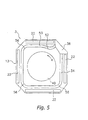
- FIG. 5 is a horizontal cross-sectional view of the indoor unit 3 of the air conditioner according to the third embodiment of the present invention.
- the cross-section of a casing 13 is square-shaped, and is beveled at the four comers. Further, an outlet 22 and an inlet (not shown) are disposed along each of the four sides of the periphery of the bottom plate.
- the turbofan 40 is disposed at the center part of the casing 13.
- a heat exchanger 34 is disposed in a substantially square shape so that it surrounds the turbofan 40 on the inner side of the outlet 22, and both ends are connected to a coolant supply unit 38, which is disposed at one comer of the casing 13. Further, because the heat exchanger 34 is disposed along each side of a square shape, it has a bent part 56 at positions corresponding to each comer. In addition, among the four linear parts of the heat exchanger 34 there is a bent part 52, which is bent so that it bulges with respect to the coolant supply unit 38 toward the interior of the casing 13 on the downstream side of the rotational direction of the turbofan 40.
- the basic operation of the indoor unit 3 is the same as the operation of the first embodiment.
- an air passageway is formed in the pathways extending from the turbofan 40 to each of the outlets 22.
- the air in the air passageway on the downstream side of the rotational direction of the turbofan 40 proximate to the coolant supply unit 38 is guided to the wall of the coolant supply unit 38, and the like, and the flow of air therein is greater than in other air passageways.
- the bent part 52 is provided in a portion positioned in the air passageway through which much air flows, and the bent part 52 has a large heat exchange surface area. Thereby, cooling and heating performance are improved because the heat exchange efficiency is improved, and because the air blown out from each of the outlets 22 is air-conditioned substantially uniformly.
- the use of the present invention enables the speed distribution of the wind blown out from the outlets to be made uniform. Thereby, the ventilation noise can be controlled, and cooling and heating performance can be maintained.
Landscapes
- Engineering & Computer Science (AREA)
- Chemical & Material Sciences (AREA)
- Combustion & Propulsion (AREA)
- Mechanical Engineering (AREA)
- General Engineering & Computer Science (AREA)
- Physics & Mathematics (AREA)
- Thermal Sciences (AREA)
- Air-Conditioning Room Units, And Self-Contained Units In General (AREA)
- Air Filters, Heat-Exchange Apparatuses, And Housings Of Air-Conditioning Units (AREA)
- Air-Flow Control Members (AREA)
- Structures Of Non-Positive Displacement Pumps (AREA)
Abstract
The object of the present invention is to provide a uniform wind speed distribution at the
outlet of an indoor unit in an air conditioner having a centrifugal fan. In addition, another object
of the present invention is to improve heat exchange efficiency without increasing the
dimensions of the indoor unit.
The indoor unit 1 of the air conditioner comprises a casing 11, a heat exchanger 30, and a
turbofan 40. Among the air passageways 35 that extend from the turbofan 40 to the outlets 20 via
the heat exchanger 30, air passageways 35b, 35d, which extend from the turbofan 40 to the outlet
20 and oppose the direction of the wind from the turbofan 40, are narrower than other air
passageways 35a, 35c.
Description
The present invention relates to an air conditioner, and more particularly relates to an air
conditioner recessed in a ceiling.
An air conditioner comprises an outdoor unit, which includes a compressor, a fan, and a
heat exchanger, and which is installed outdoors; and an indoor unit, which includes a fan and a
heat exchanger. Types of indoor units include a type attached to a wall, and a type recessed in a
ceiling.
The indoor unit of the ceiling-recessed type principally comprises a casing having an
inlet and an outlet on the bottom side, a centrifugal fan disposed inside the casing, and a heat
exchanger disposed between the centrifugal fan and the outlet. In such an indoor unit, the indoor
air is taken in from the inlet into the casing by the centrifugal fan. Further, the air taken in is
blown in the horizontal direction. Furthermore, the air delivered from the centrifugal fan is heat
exchanged in the heat exchanger, which is disposed so that it surrounds the centrifugal fan.
Subsequently, that air is supplied from the outlet to the indoor space.
The ventilation from the outlet of the air conditioner may become uneven because of the
shape of the internal ventilation unit. In particular, because a ceiling-recessed indoor unit is
disposed in the ceiling, the size of the casing is limited, and a centrifugal fan and a heat
exchanger are disposed in that limited casing space. Therefore, it is difficult to prevent the
ventilation from becoming uneven. Further, if the ventilation becomes uneven, it leads to the
generation of ventilation noise from the part where there is a strong airflow, and also leads to a
reduction in cooling and heating performance.
In addition, because the size of the heat exchanger of a ceiling-recessed indoor unit is
limited for the same abovementioned reasons, there is a need to improve as much as possible the
exchange of heat between the heat exchanger and the air in that limited space.
The object of the present invention is to provide a uniform wind speed distribution at the
outlet of an indoor unit in an air conditioner having a centrifugal fan and in addition, to improve
heat exchange efficiency without increasing the dimensions of the indoor unit.
The air conditioner as recited in Claim 1 comprises a casing, a centrifugal fan, and a heat
exchanger. The casing has an inlet for sucking in air to the inside, and outlets for blowing out air
to the outside. The centrifugal fan is disposed in the interior of the casing. The heat exchanger is
provided in the interior of the casing so that it surrounds the centrifugal fan. In addition, the heat
exchanger is disposed so that, among air passageways extending from the centrifugal fan to the
outlets via the heat exchanger, the air passageway that extends from the centrifugal fan to the
outlet and that opposes the direction of the wind from the centrifugal fan is narrower than the
other air passageway.
In the above air conditioner, driving the centrifugal fan sucks in air from the inlet into the
casing, and that air is further blown out from outlets. At that time, the air passageways formed
between the centrifugal fan and the outlets each have a different air resistance due to the shape of
the casing and the position of the outlets, as well as the mutual positional relationships of the
centrifugal fan, the heat exchanger, and the outlets. Consequently, the wind speed of the air
blown out from each of the outlets varies, which leads to the generation of ventilation noise in
some cases, as well as to a reduction in cooling and heating performance.
Specifically, there is a large volume of air from the outlets opposing the direction of the
wind from the centrifugal fan compared with the outlets not opposing the direction of the wind
from the centrifugal fan.
Furthermore, in the above air conditioner, a heat exchanger is disposed so that, among the
air passageways, the air passageways extending from the centrifugal fan to the outlets opposing
the direction of the wind are narrower compared with other air passageways. Consequently, the
air resistance of these air passageways increases, the airflow speed is held down, and the speed
distribution of the wind blown out from the outlets can be made uniform. Thereby, it is possible
to control the ventilation noise as well as to maintain cooling and heating performance.
The air conditioner according to Claim 2 is the air conditioner as recited in Claim 1,
wherein the casing is rectangular shaped. The heat exchanger has first, second, and third
proximate parts, respectively in the reverse order of the rotational direction of the centrifugal fan,
that are more proximate to the sidewalls of the casing than both sides of each of the proximate
parts. The length of a first portion of the heat exchanger between the first proximate part and the
second proximate part is substantially the same as the length of a second portion between the
second proximate part and the third proximate part.
Because of the air resistance due to the width of the air passageways, the volume of the
air blown out from the outlets becomes even, and the volume of the air that flows through the
first and second portions become substantially equal. Moreover, because the lengths of the heat
exchanger in the first and second portions are substantially equal, the heat exchange efficiencies
are substantially identical. Thereby, the heat exchange efficiencies in the air passageways
become uniform, cooling and heating efficiencies are improved, and the temperature distribution
of the air from the outlets becomes uniform.
The air conditioner as recited in Claim 3 comprises a casing, a centrifugal fan, and a heat
exchanger. The rectangular casing has an inlet for sucking in air to the inside, and outlets for
blowing out air to the outside. The centrifugal fan is disposed in the interior of the casing. The
heat exchanger is provided in the interior of the casing so that it surrounds the centrifugal fan. In
addition, the heat exchanger has first, second, and third proximate parts, respectively in the
reverse order of the rotational direction of the centrifugal fan, that are more proximate to the
casing than both sides of each of the proximate parts. The first proximate part and the third
proximate part of the heat exchanger are positioned in the vicinity of an axis, which passes
through the center of the centrifugal fan and is orthogonal to opposing first and second sidewalls
of the casing. A second proximate part of the heat exchanger is disposed so that it is offset on the
first proximate part side of the heat exchanger with respect to an axis, which passes through the
center of the centrifugal fan and is orthogonal to opposing third and fourth sidewalls of the
casing. The outlets comprises first and second outlets provided respectively in the first and
second sidewalls of the casing so that they interpose the first proximate part, and third and fourth
outlets provided so that they interpose the third proximate part.
In the above air conditioner, driving the centrifugal fan sucks in air from the inlet into the
interior of the casing, and the air is further blown out from four outlets. At this time, the air
resistance in each of the air passageways formed between the centrifugal fan and the outlets
varies by the shape of the casing, the position of the outlets, as well as the mutual positional
relationships among the centrifugal fan, the heat exchanger, and the outlets. Consequently, the
wind speed of the air blown out from each of the outlets varies, which in certain cases generates
ventilation noise and leads to a decrease in cooling and heating performance.
Specifically, in the above air conditioner, the first outlet and the second outlet are
disposed in a first sidewall of the casing so that they interpose a first proximate part.
Accordingly, if the downstream side of the rotational direction of the centrifugal fan is
provisionally made the first outlet, and the upstream side is provisionally made the second outlet,
then the wind direction of the centrifugal fan opposes the second outlet, which increases the air
volume to the second outlet. Conversely, the air volume to the first outlet is smaller than the
second outlet. This applies likewise for the third outlet and the fourth outlet.
Further, in the above air conditioner, the heat exchanger is arranged inclined with respect
to the axis that passes through the center of the centrifugal fan and that is orthogonal to the
casing sidewall. The air resistance in the air passageway extending from the centrifugal fan to the
outlets is adjusted so as to make the air volume from each of the outlets uniform.
Specifically, by offsetting the second proximate part on the first proximate part side, the
air passageway formed between the first proximate part and the second proximate part is
narrower than the air passageway formed between the third proximate part and the second
proximate part. Because the narrowed air passageway creates an air resistance to the flow of air
blown out from the centrifugal fan, the airflow that passes through the first proximate part and
the second proximate part and is blown out from the second outlet is less than the other air
passageways, and the speed distribution of the wind blown out from the outlets can be made
uniform. Thereby, the ventilation noise can be controlled, and cooling and heating performance
can also be maintained.
The air conditioner as recited in Claim 4 is the air conditioner as recited in Claim 3,
wherein the length of a first portion of the heat exchanger between the first proximate part and
the second proximate part is substantially the same as the length of a second portion between the
second proximate part and a third proximate part.
In the claim above, the heat exchange efficiencies in the air passageways are substantially
identical, the same as in Claim 2. Thereby, the heat exchange efficiencies in the air passageways
are made uniform, the cooling and heating efficiencies are improved, and the temperature
distribution of the air from each of the outlets is made uniform.
The air conditioner as recited in Claim 5 is the air conditioner as recited in Claim 2 or
Claim 4, wherein the heat exchanger comprises a bent part that is bent in the direction of the
interior of the casing in the first portion.
Because the position of the second proximate part is offset toward the first proximate part
side, it is necessary to bend the second proximate part in order to make the length of the heat
exchanger in the first and second portions equal. At this point, the heat exchanger in the first
portion is bent in a direction toward the interior of the casing. Thereby, the lengths of the heat
exchanger are equalized without the need to change the size of the casing, and the configuration
is simplified.
The air conditioner as recited in Claim 6 is the air conditioner as recited in any one claim
of Claim 1 to Claim 5, wherein the heat exchanger comprises heat exchanger main bodies and a
connecting part that connects the heat exchanger main bodies.
Bending the heat exchanger distorts the internal structure of the heat exchanger.
Consequently, there is a possibility that the process of bending the heat exchanger may create a
defect. To the extent that there are a large number of bent parts, the number of bending processes
increases, which increases the frequency of defects.
Because there were two or more heat exchangers in the indoor unit, the number of
bending processes per heat exchanger can be reduced. Thereby, the frequency of heat exchanger
defects can be controlled.
In addition, if heat exchangers of the same shape is used, the number of types of heat
exchangers to be manufactured is reduced, and the manufacturing labor and expenditures can
thereby be reduced.
The air conditioner as recited in Claim 7 comprises a casing, a centrifugal fan, a heat
exchanger, and a coolant supply unit. The casing comprises an inlet for sucking in air to the
inside, and outlets for blowing out air to the outside and which are disposed rectangularly. The
centrifugal fan is disposed in the interior of the casing. The heat exchanger is provided in the
interior of the casing so that it surrounds the centrifugal fan, and is disposed rectangularly on the
inner side of the outlets. The coolant supply unit is provided at one comer of the heat exchanger,
and supplies a coolant to the heat exchanger. The heat exchanger comprises an extension part on
the downstream side of the rotational direction of the centrifugal fan with respect to the coolant
supply unit.
In the above air conditioner, driving the centrifugal fan sucks in air from the inlet into the
interior of the casing, and the air is then further blown out from the outlets. At this time, the air
resistance in the air passageways formed between the centrifugal fan and the outlets varies by the
shape of the casing, the position of the outlets, the position of the coolant supply unit, as well as
the mutual positional relationships among the centrifugal fan, the heat exchanger, and the outlets.
Consequently, the wind speed of the air blown out from each of the outlets varies. In particular,
because a coolant supply unit is supplied, the air passageway facing the outlet near the coolant
supply unit is unfortunately narrowed. Consequently, the airflow on the downstream side of the
rotational direction of the centrifugal fan increases, creating turbulence in the airflow.
Consequently, the air delivered from the outlet in the vicinity of the coolant supply unit is blown
out without being sufficiently air-conditioned.
Further, in one of the air passageways in the above air conditioner, the heat exchanger is
provided with an extension part with respect to the coolant supply unit on the downstream side of
the rotational direction of the centrifugal fan. Thereby, cooling and heating performance can be
maintained because the conditioning of the air blown out from the outlets can be made uniform.
The air conditioner as recited in Claim 8 is the air conditioner as recited in Claim 7,
wherein the extension part is bent in the direction of the interior of the casing.
Herein, the extension part of the heat exchanger with respect to the coolant supply unit on
the downstream side of the rotational direction of the centrifugal fan is a bent part that is bent in
the direction toward the interior of the casing. Thereby, the length of the heat exchanger can be
extended without changing the size or the casing.
FIG. 1 shows an exterior perspective view of the indoor unit 1 of the air conditioner
according to the first embodiment of the present invention. FIG. 2 is a vertical cross-sectional
view and FIG. 3 is a horizontal cross-sectional view of the indoor unit at a surface that includes
the centrifugal fan.
An indoor unit 1 is a ceiling-recessed type, and comprises a casing 11 that is recessed in a
ceiling. In addition, a turbofan 40 (centrifugal fan) and a heat exchanger 30 are provided in the
casing 11. The indoor unit 1 takes in air placed in the indoor space, air conditions the air, and
supplies that air to the indoor space after it has been air-conditioned by the heat exchanger.
The casing 11 is a case that holds members of the indoor unit 1 therein. The casing 11 has
an outline shape of a rectangular parallelepiped, and has a bottom plate 12 on the bottom thereof.
An outlet 20 is formed on the outer side of the long side of the bottom plate 12, and an inlet 21 is
provided on the inner side of the outlet 20. The outlet 20 is a ventilation port for supplying air
that has been air-conditioned by the indoor unit 1 to the indoor space, and the inlet 21 is a
ventilation port for taking in air from the indoor space to the indoor unit 1. Furthermore, on one
of a pair of long sides of the casing 11, the outlet 20 has a first outlet 20a provided on the
downstream side (from the center of the long side) of the rotational direction of the turbofan 40;
and a second outlet 20b provided on the upstream side of the rotational direction. Further, on the
other long side, the outlet 20 has a third outlet 20c provided at a position opposing the second
outlet 20b on the downstream side (from the center of the long side) of the rotational direction of
turbofan 40; and a fourth outlet 20d provided at a position opposing the first outlet 20a on the
upstream side of the rotational direction.
The turbofan 40 is positioned substantially at the center of the casing 11. The turbofan 40
is provided with vanes at the periphery. By rotating in the direction of the arrow R in FIG. 3,
pushes out the air in the interior of the turbofan 40 in the rotational direction, producing an
airflow in the interior of the indoor unit 1.
The heat exchanger 30 is a member that exchanges heat with the ventilating air. Further,
the heat exchanger 30 is formed in a substantially rhombic shape so that it surrounds the turbofan
40, and has first, second, and third proximate parts 50a, 50b, and 50c that are proximate to the
inner wall of the casing 11 more than both sides of each of the proximate parts 50a, 50b, 50c,
respectively. The first proximate part 50a is positioned in the vicinity of an axis 14, which passes
through the center of the turbofan 40 and is orthogonal to the long side of the casing 11, and is
interposed between the first outlet 20a and the second outlet 20b. The third proximate part 50c is
positioned on the opposite side opposing the first proximate part 50a, and is interposed between
the third outlet 20c and the fourth outlet 20d. In addition, the second proximate part 50b is
positioned on an axis 36, which is inclined toward the second outlet 20b side (the first proximate
part 50a side) by just a predetermined angle from an axis 15, which passes through the center of
the turbofan 40 and is orthogonal to the short side of the casing 11. In addition, the heat
exchanger 30 is connected to a coolant supply unit 31 at the end part of the heat exchanger 30.
Further, the coolant supply unit 31 is disposed on the fourth outlet 20d side displaced with
respect to the axis 15.
By disposing the heat exchanger 30 as described above, an air passageway is formed
from the turbofan 40 to each of the outlets. Namely, a first air passageway 35a, which extends
from the turbofan 40 to the first outlet 20a, is formed between the coolant supply unit 31 and the
first proximate part 50a. A second air passageway 35b, which extends from the turbofan 40 to
the second outlet 20b, is formed between the first proximate part 50a and the second proximate
part 50b. A third air passageway 35c, which extends from the turbofan 40 to the third outlet 20c,
is formed between the second proximate part 50b and the third proximate part 50c. A fourth
air passageway 35d, which extends from the turbofan 40 to the fourth outlet 20d, is formed
between the third proximate part 50c and the coolant supply unit 31.
In addition, portions 30a - 30d of the heat exchanger 30 are disposed corresponding to the
air passageways 35a - 35d, respectively. In other words, among the portions of the heat
exchanger 30, the first portion 30a is disposed in the first air passageway 35a between the
coolant supply unit 31 and the first proximate part 50a, and the second portion 30b is disposed in
the second air passageway 35b between the first proximate part 50a and the second proximate
part 50b. In addition, among the portions of the heat exchanger 30, the third portion 30c is
disposed in the third air passageway 35c between the second proximate part 50b and the third
proximate part 50c, and the fourth portion 30d is disposed in the fourth air passageway 35d
between the third proximate part 50c and the coolant supply unit 31.
Further, by disposing the heat exchanger 30 inclined as discussed above, the first portion
30a and third portion 30c are shorter than the second portion 30b and fourth the portion 30d.
The following explains the operation of the indoor unit 1.
The interior of the indoor unit 1 is ventilated by the rotation of the turbofan 40. Air is
taken into the interior of the indoor unit 1 from the inlet 21, which faces the indoor space. The air
taken in is then delivered by the turbofan 40 to the surroundings thereof. The air that has been
pushed out is heat exchanged by the heat exchanger 30, which is arranged at the circumference
of the turbofan 40, and is then supplied from the outlets 20a - 20d to the indoor space.
The following discusses the wind speed (airflow) of the air passageways 35a - 35d for the
case in which the turbofan 40 has rotated.
First, let us consider the second outlet 20b and the third outlet 20c side of the axis 14.
Because of the rotational direction of the turbofan 40, and the arrangement of each of the
outlets 20b, 20c, the second outlet 20b opposes the direction of the wind from the turbofan 40,
and the wind speed of the air from the turbofan 40 increases if there is no heat exchanger 30.
However, the third outlet 20c is arranged at a position along the direction of the wind from the
turbofan 40, and does not oppose the direction of the wind from the turbofan 40. In other
words, the third outlet 20c is disposed at a position at which the wind speed of the air from the
turbofan 40 is slower if there is no heat exchanger 30. This is the same for the first outlet 20a and
the fourth outlet 20d side of the axis 14. Namely, because of the rotational direction of the
turbofan 40, and the arrangement of the outlets 20a, 20d, the wind speed of the air to the fourth
outlet 20d is faster compared with the first air passageway 35a if there is no heat exchanger 30.
However, in the present embodiment as described above, the substantially rhombically
formed heat exchanger 30 is disposed inclined with respect to the axis 15, and the widths
(lengths) of the portions of the heat exchanger 30 in the air passageways 35a - 35d to the outlets
20a - 20d are not equal. In other words, the widths of the second and fourth portions 30b, 30d are
narrower than the widths of the first and third portions 30a, 30c.
Accordingly, the air resistance when passing through the second and fourth portions 30b,
30d is greater than when passing through the first and third portions 30a, 30c. As a result, the
volume of air (wind speed) that passes through each of the air passageways 35a - 35d and that is
blown out from the air outlets 20a - 20d, respectively, are made uniform.
FIG. 4 is a horizontal cross-sectional view of the indoor unit 2 of the air conditioner
according to the second embodiment of the present invention.
In the first embodiment, the air resistance of each air passageway varies due to the offset
arrangement of the heat exchanger, and the present embodiment aims to make the air volume
from the outlets uniform. In the present embodiment, the length (i.e., the heat exchange surface
area) of each portion of the heat exchanger, wherein each portion is disposed in an air
passageway, differs. Accordingly, although the air volume from each outlet has been made
uniform, there is a risk that the temperature distribution will become uneven.
Therefore, it is an object of the second embodiment to make the temperature distribution
of the air blown out from each outlet uniform. Accordingly, the second embodiment differs from
the first embodiment only in the constitution of the heat exchanger; other constitutional aspects
are the same.
A heat exchanger main body 32 is a member that exchanges heat with the air that is
ventilated, and is disposed so that it surrounds the turbofan 40, the same as mentioned earlier.
The heat exchanger 32 comprises a first main body 321, which is disposed on the first and
second outlets 20a, 20b side of the axis 15, which passes through the center of the turbofan 40
and is orthogonal to the short side of the casing 11; and a second main body 322, which is
disposed on the third and fourth outlets 20c, 20d side, i.e., on the reverse side.
Further, the first main body 321 and the second main body 322 are connected by a
connecting member 55 at one end in the direction along the axis 15, and are connected by a
coolant supply unit 33 at the other end. Furthermore, the coolant supply unit 33 is disposed so
that it is shifted toward the fourth outlet 20d side of the axis 15.
In addition, the heat exchanger 32 has first, second, and third proximate parts 53a, 53b
and 53c that are more proximate to the inner wall of the casing 11 than both sides of each of the
proximate parts 53a, 53b, 53c. The first proximate part 53a is positioned in the vicinity of the
axis 14, and is interposed between the first outlet 20a and the second outlet 20b. The third
proximate part 53c is positioned on the reverse side of and opposing the first proximate part 53a,
and is interposed between the third outlet 20c and the fourth outlet 20d. In addition, the second
proximate part 53b is positioned in the vicinity of the axis 37, which is inclined toward the
second outlet 20b side of the axis 15 by a predetermined angle.
Disposing the heat exchanger 30 as described above forms an air passageway that
extends from the turbofan 40 to each of the outlets. Namely, the first air passageway 35a, which
extends from the turbofan 40 to the first outlet 20a, is formed between the coolant supply unit 33
and the first proximate part 53a. The second air passageway 35b, which extends from the
turbofan 40 to the second outlet 20b, is formed between the first proximate part 53a and the
second proximate part 53b. The third air passageway 35c, which extends from the turbofan 40 to
the third outlet 20c, is formed between the second proximate part 53b and the third proximate
part 53c. The fourth air passageway 35d, which extends from the turbofan 40 to the fourth outlet
20d, is formed between the third proximate part 53c and the coolant supply unit 33.
Further, among the portions of the first main body 321 of the heat exchanger 32, a first
portion 32a is disposed in the first air passageway 35a. Among the portions of the first main
body 321, a second portion 32b is disposed in the second air passageway 35b. Furthermore,
among the portions of the second main body 322 of the heat exchanger 32, a third portion 32c is
disposed in the third air passageway 35c. Among the portions of the second main body 322, a
fourth portion 32d is disposed in the fourth air passageway 35d.
A bent part 54 is formed in the first and third portions 32a, 32c of the heat exchanger 32,
such that the bent part 54 bulges toward the outer side of the casing 11, and a bent part 52 is
formed in the second and fourth portions 32b, 32d such that the bent part 52 bulges toward the
inner side of the casing 11. Thereby, the lengths of the heat exchanger in the four portions 32a-32d
are substantially equal, and the heat exchange surface of each area is accordingly
substantially equal.
The basic operation of the indoor unit 2 is the same as the operation of the first
embodiment.
As explained in the first embodiment, examining the second outlet 20b and the third
outlet 20c side of the axis 14 shows that the wind speed of the air to the second outlet 20b is
faster compared with the wind speed of the air to the third outlet 20c if there is no heat exchanger.
In addition, if we likewise examine the first outlet 20a and the fourth outlet 20d side of the axis
14, the wind speed of the air to the fourth outlet 20d is faster compared with the wind speed of
the air to the first outlet 20a.
In the same manner as the first embodiment, the second proximate part 53b in the present
embodiment is disposed inclined with respect to the axis 15, and the flow of air (wind speed) that
blows out from each of the outlets 20a - 20d is uniform. Further, bending the heat exchanger 32
makes the heat exchange surface area in each portion substantially equal, and makes the heat
exchange efficiency in each of the air passageways 35a - 35d uniform. Thereby, the cooling and
heating efficiency can be improved compared with a conventional air conditioner. In addition,
the temperature distribution of the air blown out from each of the outlets 20a - 20d can be made
uniform.
In particular, because the bent part 52 is formed in the heat exchanger 32, thus ensuring a
heat exchange surface area, the heat exchange surface area can be enlarged without increasing
the size of the indoor unit 2.
FIG. 5 is a horizontal cross-sectional view of the indoor unit 3 of the air conditioner
according to the third embodiment of the present invention.
The cross-section of a casing 13 is square-shaped, and is beveled at the four comers.
Further, an outlet 22 and an inlet (not shown) are disposed along each of the four sides of the
periphery of the bottom plate. The turbofan 40 is disposed at the center part of the casing 13.
A heat exchanger 34 is disposed in a substantially square shape so that it surrounds the
turbofan 40 on the inner side of the outlet 22, and both ends are connected to a coolant supply
unit 38, which is disposed at one comer of the casing 13. Further, because the heat exchanger 34
is disposed along each side of a square shape, it has a bent part 56 at positions corresponding to
each comer. In addition, among the four linear parts of the heat exchanger 34 there is a bent part
52, which is bent so that it bulges with respect to the coolant supply unit 38 toward the interior of
the casing 13 on the downstream side of the rotational direction of the turbofan 40.
The basic operation of the indoor unit 3 is the same as the operation of the first
embodiment.
In the present embodiment, the same as in the abovementioned embodiment, an air
passageway is formed in the pathways extending from the turbofan 40 to each of the outlets 22.
However, among the four air passageways, the air in the air passageway on the downstream side
of the rotational direction of the turbofan 40 proximate to the coolant supply unit 38 is guided to
the wall of the coolant supply unit 38, and the like, and the flow of air therein is greater than in
other air passageways.
Further, among the air passageways of the heat exchanger in the present embodiment, the
bent part 52 is provided in a portion positioned in the air passageway through which much air
flows, and the bent part 52 has a large heat exchange surface area. Thereby, cooling and heating
performance are improved because the heat exchange efficiency is improved, and because the air
blown out from each of the outlets 22 is air-conditioned substantially uniformly.
The use of the present invention enables the speed distribution of the wind blown out
from the outlets to be made uniform. Thereby, the ventilation noise can be controlled, and
cooling and heating performance can be maintained.
Claims (8)
- An air conditioner (1), comprising:wherein,a casing (11) having an inlet (21) for sucking in air to the inside, and outlets (20) for blowing out air to the outside;a centrifugal fan (40), disposed in the interior of said casing (11); anda heat exchanger (30) provided in the interior of said casing (11) so that it surrounds said centrifugal fan (40);
said heat exchanger (30) is disposed so that, among air passageways (35b, 35c) extending from said centrifugal fan (40) to said outlets (20) via said heat exchanger (30), the air passageway (35b) that extends from said centrifugal fan to said outlet (20) and that opposes the direction of the wind from said centrifugal fan is narrower than said other air passageway (35c). - The air conditioner (2) as recited in Claim 1, wherein
said casing (11) is rectangular shaped;
said heat exchanger (32) has first, second, and third proximate parts (53a, 53b, 53c), respectively in the reverse order of the rotational direction (R) of said centrifugal fan, that are more proximate to the sidewalls of said casing (11) than both sides of each of said proximate parts (53a, 53b, 53c); and
the length of a first portion (32b) of said heat exchanger (32) between said first proximate part (53a) and said second proximate part (53b) is substantially the same as the length of a second portion (32c) between said second proximate part (53b) and said third proximate part (53c). - An air conditioner (1), comprising:wherein,a rectangular casing (11) having an inlet (21) for sucking in air to the inside, and outlets (20) for blowing out air to the outside;a centrifugal fan (40) disposed in the interior of said casing (11); anda heat exchanger (30) provided in the interior of said casing (11) so that it surrounds said centrifugal fan (40);
said heat exchanger (30) has first, second, and third proximate parts (50a, 50b, 50c), respectively in the reverse order of the rotational direction (R) of said centrifugal fan (40), that are more proximate to said casing (11) than both sides of each of said proximate
parts (50a, 50b, 50c);
said first proximate part (50a) and said third proximate part (50c) of said heat exchanger (30) are positioned in the vicinity of an axis (14), which passes through the center of said centrifugal fan (40) and is orthogonal to opposing first and second sidewalls of said casing (11), and said second proximate part (50b) of said heat exchanger (30, 32) is disposed so that it is offset on the first proximate part (50a) side of said heat exchanger (30) with respect to an axis (15), which passes through the center of said centrifugal fan (40) and is orthogonal to opposing third and fourth sidewalls of said casing (11); and said outlets (20) comprises first and second outlets (20a, 20b) provided respectively in said first and second sidewalls of said casing (11) so that they interpose said first proximate part (50a); and third and fourth outlets (20c, 20d) provided so that they interpose said third proximate part (50c). - The air conditioner (2) as recited in Claim 3, wherein
the length of a first portion (32b) of said heat exchanger (32) between said first proximate part (53a) and said second proximate part (53b) is substantially the same as the length of a second portion (32c) between said second proximate part (53b) and a third proximate part (53c). - The air conditioner (2) as recited in Claim 2 or Claim 4, wherein
said heat exchanger (32) comprises a bent part (52) that is bent in the direction of the interior of said casing (11) in said first portion (32b). - The air conditioner (2) as recited in any one claim of Claim 1 to Claim 5, wherein
said heat exchanger (32) comprises heat exchanger main bodies (321, 322), and a connecting part (55) that connects said heat exchanger main bodies (321, 322). - An air conditioner (3), comprising:wherein,a casing (13) comprising an inlet (21) for sucking in air to the inside, and outlets (22) for blowing out air to the outside and which are disposed rectangularly;a centrifugal fan (40) disposed in the interior of said casing (13);a heat exchanger (34) provided in the interior of said casing ( 13) so that it surrounds said centrifugal fan (40), and is disposed rectangularly on the inner side of said outlets (22); anda coolant supply unit (38) provided at one comer of said rectangular heat exchanger (34), and that supplies a coolant to said heat exchanger (34);
said heat exchanger (34) comprises an extension part (52) on the downstream side of the rotational direction (R) of said centrifugal fan (40) with respect to said coolant supply unit (38). - The air conditioner (3) as recited in Claim 7, wherein
said extension part (52) is bent in the direction of the interior of said casing (11).
Applications Claiming Priority (3)
| Application Number | Priority Date | Filing Date | Title |
|---|---|---|---|
| JP2001099393 | 2001-03-30 | ||
| JP2001099393A JP4724939B2 (en) | 2001-03-30 | 2001-03-30 | Air conditioner |
| PCT/JP2002/002224 WO2002081974A1 (en) | 2001-03-30 | 2002-03-08 | Air conditioner |
Publications (2)
| Publication Number | Publication Date |
|---|---|
| EP1382917A1 true EP1382917A1 (en) | 2004-01-21 |
| EP1382917A4 EP1382917A4 (en) | 2007-03-14 |
Family
ID=18952935
Family Applications (1)
| Application Number | Title | Priority Date | Filing Date |
|---|---|---|---|
| EP02702856A Withdrawn EP1382917A4 (en) | 2001-03-30 | 2002-03-08 | AIR CONDITIONING |
Country Status (5)
| Country | Link |
|---|---|
| EP (1) | EP1382917A4 (en) |
| JP (1) | JP4724939B2 (en) |
| CN (2) | CN2526722Y (en) |
| AU (1) | AU2002236276B2 (en) |
| WO (1) | WO2002081974A1 (en) |
Cited By (6)
| Publication number | Priority date | Publication date | Assignee | Title |
|---|---|---|---|---|
| EP1947397A4 (en) * | 2005-11-11 | 2011-01-19 | Daikin Ind Ltd | INTERIOR AIR CONDITIONER PANEL AND AIR CONDITIONER |
| EP1975519A4 (en) * | 2006-01-04 | 2013-04-03 | Daikin Ind Ltd | INDOOR UNIT FOR AIR CONDITIONER |
| EP2827071A4 (en) * | 2012-03-16 | 2015-12-09 | Daikin Ind Ltd | BIDIRECTIONAL PURGE, CEILING INTEGRATED AIR CONDITIONER |
| EP3614057A4 (en) * | 2017-05-24 | 2020-04-15 | Daikin Industries, Ltd. | Indoor unit for air conditioner |
| EP3614064A4 (en) * | 2017-05-24 | 2020-04-15 | Daikin Industries, Ltd. | INDOOR UNIT FOR AIR CONDITIONER |
| EP3798523A4 (en) * | 2019-01-14 | 2021-09-29 | Qingdao Haier Air-Conditioning Electronic Co., Ltd | Heat exchanger applied to ceiling air conditioner and ceiling air conditioner |
Families Citing this family (5)
| Publication number | Priority date | Publication date | Assignee | Title |
|---|---|---|---|---|
| JP4141368B2 (en) * | 2003-10-10 | 2008-08-27 | 三洋電機株式会社 | Embedded ceiling air conditioner |
| CN105156345B (en) * | 2015-09-11 | 2018-06-22 | 珠海格力电器股份有限公司 | Vertical air conditioner |
| JP6409907B1 (en) * | 2017-05-24 | 2018-10-24 | ダイキン工業株式会社 | Air conditioner indoor unit |
| WO2021059328A1 (en) * | 2019-09-24 | 2021-04-01 | 東芝キヤリア株式会社 | Indoor unit for refrigeration cycle device and impeller |
| CN111947068A (en) * | 2020-08-07 | 2020-11-17 | 江西旺来科技有限公司 | An air purifying anti-dazzling light |
Family Cites Families (11)
| Publication number | Priority date | Publication date | Assignee | Title |
|---|---|---|---|---|
| JPS62162830A (en) * | 1986-01-13 | 1987-07-18 | Matsushita Electric Ind Co Ltd | air conditioner |
| JPH0450318A (en) * | 1990-06-12 | 1992-02-19 | Kanebo Ltd | Spun-dyed polyester yarn having excellent light resistance |
| JPH055536A (en) * | 1990-11-07 | 1993-01-14 | Daikin Ind Ltd | Air conditioner |
| JP3606968B2 (en) * | 1995-11-08 | 2005-01-05 | 三菱電機株式会社 | Air conditioner |
| JPH09229467A (en) * | 1996-02-26 | 1997-09-05 | Matsushita Refrig Co Ltd | Heat exchanger |
| JPH11148711A (en) * | 1997-11-14 | 1999-06-02 | Mitsubishi Heavy Ind Ltd | Ceiling-mounted air conditioner |
| JPH11153344A (en) * | 1997-11-21 | 1999-06-08 | Mitsubishi Heavy Ind Ltd | Air conditioner |
| JP2000046360A (en) * | 1998-07-29 | 2000-02-18 | Hitachi Ltd | Ceiling-mounted indoor unit |
| JP2000121089A (en) * | 1998-10-20 | 2000-04-28 | Hitachi Ltd | Air conditioner |
| JP3521323B2 (en) * | 1998-12-18 | 2004-04-19 | 株式会社日立製作所 | In-ceiling indoor unit |
| JP2000220859A (en) * | 1999-02-01 | 2000-08-08 | Hitachi Ltd | Air conditioner |
-
2001
- 2001-03-30 JP JP2001099393A patent/JP4724939B2/en not_active Expired - Fee Related
-
2002
- 2002-01-28 CN CN02204366U patent/CN2526722Y/en not_active Expired - Fee Related
- 2002-01-28 CN CNB021033633A patent/CN1184438C/en not_active Expired - Fee Related
- 2002-03-08 WO PCT/JP2002/002224 patent/WO2002081974A1/en not_active Ceased
- 2002-03-08 AU AU2002236276A patent/AU2002236276B2/en not_active Ceased
- 2002-03-08 EP EP02702856A patent/EP1382917A4/en not_active Withdrawn
Cited By (7)
| Publication number | Priority date | Publication date | Assignee | Title |
|---|---|---|---|---|
| EP1947397A4 (en) * | 2005-11-11 | 2011-01-19 | Daikin Ind Ltd | INTERIOR AIR CONDITIONER PANEL AND AIR CONDITIONER |
| US8230693B2 (en) | 2005-11-11 | 2012-07-31 | Daikin Industries, Ltd. | Interior panel of air conditioner and air conditioner |
| EP1975519A4 (en) * | 2006-01-04 | 2013-04-03 | Daikin Ind Ltd | INDOOR UNIT FOR AIR CONDITIONER |
| EP2827071A4 (en) * | 2012-03-16 | 2015-12-09 | Daikin Ind Ltd | BIDIRECTIONAL PURGE, CEILING INTEGRATED AIR CONDITIONER |
| EP3614057A4 (en) * | 2017-05-24 | 2020-04-15 | Daikin Industries, Ltd. | Indoor unit for air conditioner |
| EP3614064A4 (en) * | 2017-05-24 | 2020-04-15 | Daikin Industries, Ltd. | INDOOR UNIT FOR AIR CONDITIONER |
| EP3798523A4 (en) * | 2019-01-14 | 2021-09-29 | Qingdao Haier Air-Conditioning Electronic Co., Ltd | Heat exchanger applied to ceiling air conditioner and ceiling air conditioner |
Also Published As
| Publication number | Publication date |
|---|---|
| WO2002081974A1 (en) | 2002-10-17 |
| CN1184438C (en) | 2005-01-12 |
| JP2002295891A (en) | 2002-10-09 |
| CN1379213A (en) | 2002-11-13 |
| JP4724939B2 (en) | 2011-07-13 |
| AU2002236276B2 (en) | 2005-04-21 |
| EP1382917A4 (en) | 2007-03-14 |
| CN2526722Y (en) | 2002-12-18 |
Similar Documents
| Publication | Publication Date | Title |
|---|---|---|
| US8006512B2 (en) | Air conditioner | |
| EP2626646B1 (en) | Air conditioner | |
| EP1041351B1 (en) | Indoor unit for air conditioner | |
| KR100344593B1 (en) | Air-conditioner | |
| JP6022003B2 (en) | Air conditioner indoor unit | |
| US20120015599A1 (en) | Air conditioner, casing, and decorative panel | |
| EP3364117B1 (en) | Air conditioner indoor unit | |
| AU2002236276B2 (en) | Air Conditioner | |
| EP1316760B1 (en) | Decorative panel for air conditioning system, air outlet blow-off unit, and air conditioning system | |
| JP2001124359A (en) | Air conditioner | |
| JP2001263703A (en) | Ceiling-mounted air conditioner | |
| JP3991477B2 (en) | Air conditioner indoor unit | |
| CN115315598B (en) | Indoor unit of air conditioner | |
| CN101398239A (en) | Heat exchanger | |
| EP1052457B1 (en) | Indoor unit for air conditioner | |
| KR20040015872A (en) | An air-conditioner | |
| JP6923845B2 (en) | Duct type air conditioner | |
| JP2000171052A (en) | Ceiling-mounted air conditioner | |
| JP4280869B2 (en) | Indoor unit for air conditioning | |
| JP7639104B2 (en) | Louvers, air outlets and rotating units | |
| KR102956461B1 (en) | Air Conditioner | |
| JPH0514592U (en) | Cross-flow fan for air conditioner | |
| JPH04273923A (en) | Air-conditioner | |
| JP2001248989A (en) | Heat exchanger and air conditioner provided with the heat exchanger | |
| KR200312467Y1 (en) | Structure of grill to Air-conditioner filled in ceiling |
Legal Events
| Date | Code | Title | Description |
|---|---|---|---|
| PUAI | Public reference made under article 153(3) epc to a published international application that has entered the european phase |
Free format text: ORIGINAL CODE: 0009012 |
|
| 17P | Request for examination filed |
Effective date: 20031007 |
|
| AK | Designated contracting states |
Kind code of ref document: A1 Designated state(s): AT BE CH CY DE DK ES FI FR GB GR IE IT LI LU MC NL PT SE TR |
|
| A4 | Supplementary search report drawn up and despatched |
Effective date: 20070212 |
|
| 17Q | First examination report despatched |
Effective date: 20071029 |
|
| STAA | Information on the status of an ep patent application or granted ep patent |
Free format text: STATUS: THE APPLICATION IS DEEMED TO BE WITHDRAWN |
|
| 18D | Application deemed to be withdrawn |
Effective date: 20090120 |