EP1382856A1 - Blower and air conditioner with the blower - Google Patents
Blower and air conditioner with the blower Download PDFInfo
- Publication number
- EP1382856A1 EP1382856A1 EP01274219A EP01274219A EP1382856A1 EP 1382856 A1 EP1382856 A1 EP 1382856A1 EP 01274219 A EP01274219 A EP 01274219A EP 01274219 A EP01274219 A EP 01274219A EP 1382856 A1 EP1382856 A1 EP 1382856A1
- Authority
- EP
- European Patent Office
- Prior art keywords
- blade
- blower
- trailing edge
- pressure surface
- negative pressure
- Prior art date
- Legal status (The legal status is an assumption and is not a legal conclusion. Google has not performed a legal analysis and makes no representation as to the accuracy of the status listed.)
- Granted
Links
Images




Classifications
-
- F—MECHANICAL ENGINEERING; LIGHTING; HEATING; WEAPONS; BLASTING
- F04—POSITIVE - DISPLACEMENT MACHINES FOR LIQUIDS; PUMPS FOR LIQUIDS OR ELASTIC FLUIDS
- F04D—NON-POSITIVE-DISPLACEMENT PUMPS
- F04D29/00—Details, component parts, or accessories
- F04D29/26—Rotors specially for elastic fluids
- F04D29/28—Rotors specially for elastic fluids for centrifugal or helico-centrifugal pumps for radial-flow or helico-centrifugal pumps
- F04D29/30—Vanes
-
- F—MECHANICAL ENGINEERING; LIGHTING; HEATING; WEAPONS; BLASTING
- F04—POSITIVE - DISPLACEMENT MACHINES FOR LIQUIDS; PUMPS FOR LIQUIDS OR ELASTIC FLUIDS
- F04D—NON-POSITIVE-DISPLACEMENT PUMPS
- F04D29/00—Details, component parts, or accessories
- F04D29/26—Rotors specially for elastic fluids
- F04D29/32—Rotors specially for elastic fluids for axial flow pumps
- F04D29/38—Blades
- F04D29/384—Blades characterised by form
-
- F—MECHANICAL ENGINEERING; LIGHTING; HEATING; WEAPONS; BLASTING
- F24—HEATING; RANGES; VENTILATING
- F24F—AIR-CONDITIONING; AIR-HUMIDIFICATION; VENTILATION; USE OF AIR CURRENTS FOR SCREENING
- F24F1/00—Room units for air-conditioning, e.g. separate or self-contained units or units receiving primary air from a central station
- F24F1/0007—Indoor units, e.g. fan coil units
- F24F1/0018—Indoor units, e.g. fan coil units characterised by fans
- F24F1/0029—Axial fans
-
- F—MECHANICAL ENGINEERING; LIGHTING; HEATING; WEAPONS; BLASTING
- F05—INDEXING SCHEMES RELATING TO ENGINES OR PUMPS IN VARIOUS SUBCLASSES OF CLASSES F01-F04
- F05D—INDEXING SCHEME FOR ASPECTS RELATING TO NON-POSITIVE-DISPLACEMENT MACHINES OR ENGINES, GAS-TURBINES OR JET-PROPULSION PLANTS
- F05D2240/00—Components
- F05D2240/20—Rotors
- F05D2240/30—Characteristics of rotor blades, i.e. of any element transforming dynamic fluid energy to or from rotational energy and being attached to a rotor
- F05D2240/304—Characteristics of rotor blades, i.e. of any element transforming dynamic fluid energy to or from rotational energy and being attached to a rotor related to the trailing edge of a rotor blade
Definitions
- the present invention relates to a blower characterized in its blade structure and an air conditioner having the blower.
- Fig. 17 shows a conventional common axial blower Z 0 .
- This axial blower Z 0 is constituted such that an impeller 21 formed by radially disposing a plurality of blades 23, 23, ... around the outer periphery of a hub 22 is driven to rotate by a motor 24, and that a bell mouth 25 is disposed in such a manner as to surround the impeller 21.
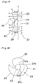
- each blade 23 of the impeller 21 is a sweapt-forward blade obtained by proceeding its leading edge 23a frontward in the rotation direction, and is also a thick blade wing having a cross section of a streamline shape that is attached to the hub 22 at a predetermined blade angle, as shown in Figs. 18 and 19.
- the blade 23 has a curved form with an appropriate "camber” or a curve in its chord direction.
- the concave side surface of the blade is a face, or pressure surface 23c, and its convex side surface is a suction surface, or negative pressure surface 23d.
- an airflow that flows in from the leading edge 23a side of the blade 23 collides with the leading edge 23a is divided to flow separately along the pressure surface 23c and along the negative pressure surface 23d, and then discharged from the trailing edge 23b side to the rear.
- the airflow is raised in pressure by a lift action at the pressure surface 23c and discharged or blown off toward a direction of arrow A.
- the angle difference between the airflow discharge direction at the trailing edge 23b (that is, a direction of a tangent line to the curved surface in the vicinity of the trailing edge 23b) and the rotation direction of the blade 23 is large.
- an airflow A 1 that flows along the pressure surface 23c and is discharged from the trailing edge 23b rearwards receives a deflecting action to flow along the blade rotation direction immediately after blown off from the trailing edge 23b. Consequently, the flow becomes unstable, and turbulence easily occurs.
- this flow is merged with the rear stream A 0 , the turbulence of the rear stream A 0 is promoted, and the width of the stream in the blade thickness direction, that is, the rear stream width S is increased.
- the problem of the increase in power consumption of the blower is relatively easily recognized when the blower is used alone.
- a blower is incorporated in equipment such as, for example, an air conditioner
- power consumption of the blower is very low in comparison with power consumption of other component members such as, for example, a compressor. Accordingly, when power consumption of the whole air conditioner is examined in view of energy saving property, attention has been paid to the compressor with high power consumption, but the power consumption of the blower has rarely been considered as a problem.
- the blower is also required to have an energy saving property, and in order to achieve this requirement, development of a technique for increasing efficiency of the blower is being required.
- an object of the present invention is to provide a blower in which high efficiency is achieved by improving a blade structure, and an air conditioner equipped with this blower.
- the present invention provides a blower having an impeller formed by radially attaching a plurality of blades to an outer periphery of a hub, characterized in that each blade has a specific region that extends in a predetermined width along a trailing edge of the blade in a wingspan direction, the specific region being bent towards a negative pressure surface side.
- a blower having the above constitution is employed as the blower.
- This air conditioner is imparted with both higher efficiency and energy saving property by including the blower having the above constitution.
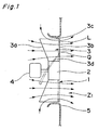
- Fig. 1 shows an axial blower Z 1 according to a first embodiment of the invention.
- This axial blower Z 1 is a so-called "propeller fan", and is constituted such that an impeller 1 formed by radially mounting a plurality of (three in this embodiment) blades 3, 3, 3 onto the outer periphery of a hub 2 at a predetermined blade angle can be driven to rotate by a motor 4, and a bell mouth 5 is disposed in such a manner as to surround this impeller 1.
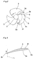
- Each blade 3 of the impeller 1 is a "sweapt-forward blade", whose leading edge 3a extends towards the front side in the rotation direction as shown in Figs. 2 and 3.
- the blade 3 is also a so-called “airfoil wing”, which has a relatively large blade thickness, with this thickness gradually reduced from a blade leading edge 3a towards a blade trailing edge 3b, and has a predetermined "camber" in the chord direction.
- a concave side surface of the blade is a pressure surface, or acting face 3e, and its convex side surface is a negative pressure surface, or suction surface 3f.
- this blade 3 a region extending in a predetermined width along the trailing edge 3b in the wingspan direction of the blade 3 (a region closer to the trailing edge 3b than line L in Figs. 1-3) is designated as a specific region Q, and that the blade is bent towards the negative pressure surface 3f side in this specific region Q. Therefore, in the blade 3 of this embodiment, a portion closer to the leading edge 3a and a portion closer to the trailing edge 3b relative to the line L serving as a boundary between the two portions have respective "cambers" in reverse directions. Such an arrangement of the "cambers" is novel and totally different from the one where a "camber" continues in only one direction from the leading edge 23a through the trailing edge 23b as in the conventional blade 23 shown in Fig. 19.
- the negative pressure surface 3f has a reduced airflow A 2 separation area on the trailing edge 3b side, and the flow of the rear stream A 0 is suppressed accordingly by the amount of reduction of the airflow A 2 separation area.
- the specific region Q is bent towards the negative pressure surface 3f sides, the discharge direction of the airflow A 1 to the rear at the trailing edge 3b becomes closer to the rotation direction of the blade 3, and the angular difference between these directions is reduced.
- the discharge of the airflow A 1 becomes smoother, so that even if this flow is merged with the rear stream A 0 , increase of the turbulence in the rear stream A 0 is suppressed and stabilization of the rear stream A 0 is promoted accordingly.
- an increase of the rear stream width S is suppressed.
- the aerodynamic characteristics of the blades 3 are improved by the degree of suppression of the increase of the rear stream width S, and the efficiency of the axial blower Z 1 is improved.
- the degree of this efficiency improvement the power consumption is reduced and the energy saving property is also improved.
- the axial blower Z 1 of this embodiment is constituted such that only the specific region Q on the trailing edge 3b side of the blade 3 is bent towards the negative pressure surface 23d side, reduction of the lifting action of the pressure surface 3e due to the presence of the specific region Q is suppressed as much as possible, and the static pressure characteristic is favorably maintained.
- Figs. 14-16 show results of various performance tests to confirm each of the above effects in the axial blower Z 1 of this embodiment.
- Fig. 14 is an "air quantity - static pressure" characteristic graph.
- a curve La1 shows a characteristic of the axial blower Z 1 of the above embodiment.
- a curve Lb1 shows a characteristic of an axial blower having a conventional structure.
- This "air quantity - static pressure" characteristic graph in Fig. 14 shows that the static pressure performance of the axial blower Z 1 of this embodiment is lower than that of the conventional blower to some extent because, in the axial blower Z 1 of the embodiment, an effective area of the acting face 3e, that is, the area of a portion involved in the air pressure raising action is reduced by bending the specific region Q portion on the trailing edge 3b side of the blade 3 towards the negative pressure surface 3f side.
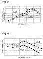
- Fig. 15 is an "air quantity - total pressure efficiency" characteristic graph.
- a curve La2 shows a characteristic of the axial blower Z 1 of this embodiment.
- a curve Lb2 shows a characteristic of an axial blower with a conventional structure. It is apparent from this "air quantity - total pressure efficiency" characteristic graph in Fig. 15 that the axial blower Z 1 of the embodiment has higher total pressure efficiency than that of the conventional axial blower.
- Fig. 16 is an "air quantity - shaft power" characteristic diagram.
- a curve La3 shows a characteristic of the axial blower Z 1 of the above embodiment.
- a curve Lb3 shows a characteristic of an axial blower having a conventional structure. It is apparent from this "air quantity - shaft power" characteristic graph in Fig. 16 that the shaft power of the axial blower Z 1 of the embodiment is significantly lower than the shaft power of the conventional axial blower.
- the static pressure performance is maintained high although slightly lower than that of the conventional blower.
- the axial blower Z 1 of this embodiment is more excellent than the blower of the conventional structure, and particularly in the shaft power the embodiment is much superior. Therefore, when these performances are compared and considered, it can be said that the axial blower Z 1 of this embodiment is highly efficient and excellent in energy saving property in total in comparison with the blower of the conventional structure.
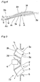
- Fig. 5 shows a mixed flow blower Z 2 according to a second embodiment of the invention.
- This axial blower Z 2 is constituted such that an impeller 1 formed by radially mounting a plurality of (four in this embodiment) blades 3, 3, 3 onto the outer periphery of a hub 2 in the shape of a truncated cone at a predetermined blade angle can be driven to rotate by a motor 4, and a bell mouth 5 is disposed in such a manner as to surround this impeller 1.
- Each blade 3 of the impeller 1 is a "sweapt-forward blade", whose leading edge 3a extends towards the front side in the rotation direction as shown in Figs. 6 and 7.
- the blade 3 is also a so-called “airfoil wing”, which has a relatively large blade thickness, with this thickness gradually reduced from a leading edge 3a towards a trailing edge 3b, and has a predetermined "camber” in the chord direction, as shown in Fig. 3.
- a concave side surface of the blade is a pressure surface, or acting face 3e, and its convex side surface is a negative pressure surface, or suction surface 3f.
- this blade 3 is that, when a region extending in a predetermined width along the trailing edge 3b in the wingspan direction of the blade 3 (a region closer to the trailing edge 3b than line L in Figs. 5-7) is assumed as a specific region Q, the blade is bent towards the negative pressure surface 3f side in this specific region Q. Therefore, in the blade 3 of this embodiment, a portion closer to the leading edge 3a and a portion closer to the trailing edge 3b with the region line L as a boundary have respective "cambers" in reverse directions. Such an arrangement of the "cambers" is novel and totally different from the structure of the conventional blade 23 (see Fig. 19).
- the mixed flow blower Z 2 having the impeller 1 with the blades 3 of such a novel constitution has the same effects as the first embodiment axial blower Z 1 , except that the direction of flow of the air as discharged (blown off) is different between these blowers. Therefore, the above-description on the effects of the first embodiment is incorporated by reference as the effects of the second embodiment and further description is omitted.
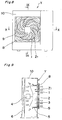
- Figs. 8-10 show an outdoor unit Y of an air conditioner equipped with the axial blower Z 1 according to the first embodiment.
- a rectangular box-like casing 10 is partitioned by a partition wall 11.
- One side of the wall is used a heat exchange chamber 12, and the other side is used as a machine chamber 13.
- the axial blower Z 1 and a heat exchanger 6 are disposed in the heat exchange chamber 12, and a compressor 7 is disposed in the machine chamber 13.
- an outlet port 9 faced by the axial blower Z 1 is equipped with a grill 8.
- the outdoor unit Y of this embodiment is equipped with, as an air supply means to the heat exchanger 6, the axial blower Z 1 according to the first embodiment, which is highly efficient and excellent in energy saving property with low power consumption, it is an ideal outdoor unit having both high heat exchange efficiency and energy saving property.
- a thick "airfoil wing" as shown in Fig. 3 is adopted as the blade 3.
- a thin "airfoil wing” as shown in Fig. 7 is adopted as the blade 3.
- the blade 3 of the present invention is not limited to these forms, but various forms such as those shown in Figs. 11-13 can be adopted.
- the blade 3 shown in Fig. 11 is an airfoil wing having a special form wherein a portion closer to its leading edge 3a is made locally thick, and the other portions are made thin.
- the blade 3 shown in Fig. 12 is an airfoil wing having a special form, wherein a relatively large portion closer to its leading edge 3a is made thick, and the blade thickness is gradually reduced from this thick portion towards the trailing edge 3b.
- the blade 3 shown in Fig. 13 is a plate wing formed by bending a thin plate having a certain thickness with a predetermined "camber".
- the same effects as those of the blowers Z 1 , Z 2 according to the first and second embodiments are obtained by bending a predetermined region on the trailing edge 3b side (that is, the specific region Q) towards the negative pressure surface 3f side.
Landscapes
- Engineering & Computer Science (AREA)
- Mechanical Engineering (AREA)
- General Engineering & Computer Science (AREA)
- Chemical & Material Sciences (AREA)
- Combustion & Propulsion (AREA)
- Structures Of Non-Positive Displacement Pumps (AREA)
Abstract
Description
Claims (5)
- A blower having an impeller (1) formed by radially attaching a plurality of blades (3, 3, ...) to an outer periphery of a hub (2), characterized in that:each blade (3) has a specific region (Q) that extends in a predetermined width along a trailing edge (3b) of the blade in a wingspan direction, said specific region being bent towards a negative pressure surface (3f) side of the blade.
- A blower according to claim 1, wherein each blade (3) has a substantially even blade thickness from a leading edge (3a) thereof to the trailing edge (3b).
- A blower according to claim 1, wherein each blade (3) has a streamline-shaped cross section.
- A blower according to claim 1, wherein the blower is provided in an air conditioner.
- An air conditioner having a heat exchanger (6) and a blower (z1, Z2), characterized in that:a blower according to claim 1, 2, or 3 is adopted as the blower (z1, Z2).
Applications Claiming Priority (3)
| Application Number | Priority Date | Filing Date | Title |
|---|---|---|---|
| JP2001129321 | 2001-04-26 | ||
| JP2001129321 | 2001-04-26 | ||
| PCT/JP2001/011317 WO2002090777A1 (en) | 2001-04-26 | 2001-12-25 | Blower and air conditioner with the blower |
Publications (3)
| Publication Number | Publication Date |
|---|---|
| EP1382856A1 true EP1382856A1 (en) | 2004-01-21 |
| EP1382856A4 EP1382856A4 (en) | 2005-01-05 |
| EP1382856B1 EP1382856B1 (en) | 2006-03-22 |
Family
ID=18977863
Family Applications (1)
| Application Number | Title | Priority Date | Filing Date |
|---|---|---|---|
| EP20010274219 Expired - Lifetime EP1382856B1 (en) | 2001-04-26 | 2001-12-25 | Blower and air conditioner with the blower |
Country Status (7)
| Country | Link |
|---|---|
| EP (1) | EP1382856B1 (en) |
| CN (1) | CN1201090C (en) |
| AU (1) | AU2002217482B2 (en) |
| DE (1) | DE60118103T2 (en) |
| ES (1) | ES2263554T3 (en) |
| TW (1) | TW524928B (en) |
| WO (1) | WO2002090777A1 (en) |
Cited By (3)
| Publication number | Priority date | Publication date | Assignee | Title |
|---|---|---|---|---|
| EP1610068A4 (en) * | 2003-03-31 | 2007-11-21 | Toshiba Carrier Corp | EXTERNAL UNIT FOR AIR CONDITIONING |
| EP1783376A4 (en) * | 2004-07-26 | 2010-03-31 | Mitsubishi Electric Corp | Blower |
| US8197217B2 (en) | 2005-08-01 | 2012-06-12 | Daikin Industries, Ltd. | Axial flow fan |
Families Citing this family (4)
| Publication number | Priority date | Publication date | Assignee | Title |
|---|---|---|---|---|
| FR2953571B1 (en) * | 2009-12-07 | 2018-07-13 | Valeo Systemes Thermiques | FAN PROPELLER, ESPECIALLY FOR A MOTOR VEHICLE |
| EP2570677B1 (en) * | 2010-05-13 | 2019-01-23 | Mitsubishi Electric Corporation | Axial flow blower |
| CN103185037B (en) * | 2011-12-28 | 2015-12-02 | 珠海格力电器股份有限公司 | Axial fan and air conditioner with same |
| CN220319900U (en) * | 2023-07-31 | 2024-01-09 | 中山宜必思科技有限公司 | A sheet metal centrifugal wind wheel |
Family Cites Families (6)
| Publication number | Priority date | Publication date | Assignee | Title |
|---|---|---|---|---|
| JPS5851435Y2 (en) * | 1975-12-17 | 1983-11-22 | アイシンセイキ カブシキガイシヤ | Engine Ray Kiyakuyo Ikomigata Silent Fan |
| JPH0285898U (en) * | 1988-12-21 | 1990-07-06 | ||
| NL1007774C1 (en) * | 1997-12-12 | 1999-06-15 | Arthur Van Moerkerken | Improved wing and propeller blade shape. |
| JP3204208B2 (en) * | 1998-04-14 | 2001-09-04 | 松下電器産業株式会社 | Mixed-flow blower impeller |
| US6116856A (en) * | 1998-09-18 | 2000-09-12 | Patterson Technique, Inc. | Bi-directional fan having asymmetric, reversible blades |
| JP4153601B2 (en) * | 1998-10-02 | 2008-09-24 | 東芝キヤリア株式会社 | Axial blower |
-
2001
- 2001-12-12 TW TW90130757A patent/TW524928B/en not_active IP Right Cessation
- 2001-12-25 CN CNB018146686A patent/CN1201090C/en not_active Expired - Fee Related
- 2001-12-25 ES ES01274219T patent/ES2263554T3/en not_active Expired - Lifetime
- 2001-12-25 DE DE2001618103 patent/DE60118103T2/en not_active Expired - Lifetime
- 2001-12-25 EP EP20010274219 patent/EP1382856B1/en not_active Expired - Lifetime
- 2001-12-25 AU AU2002217482A patent/AU2002217482B2/en not_active Ceased
- 2001-12-25 WO PCT/JP2001/011317 patent/WO2002090777A1/en not_active Ceased
Cited By (4)
| Publication number | Priority date | Publication date | Assignee | Title |
|---|---|---|---|---|
| EP1610068A4 (en) * | 2003-03-31 | 2007-11-21 | Toshiba Carrier Corp | EXTERNAL UNIT FOR AIR CONDITIONING |
| EP1783376A4 (en) * | 2004-07-26 | 2010-03-31 | Mitsubishi Electric Corp | Blower |
| US8007243B2 (en) * | 2004-07-26 | 2011-08-30 | Mitsubishi Electric Corporation | Blower including blades attached to a boss |
| US8197217B2 (en) | 2005-08-01 | 2012-06-12 | Daikin Industries, Ltd. | Axial flow fan |
Also Published As
| Publication number | Publication date |
|---|---|
| TW524928B (en) | 2003-03-21 |
| CN1449472A (en) | 2003-10-15 |
| WO2002090777A1 (en) | 2002-11-14 |
| EP1382856B1 (en) | 2006-03-22 |
| ES2263554T3 (en) | 2006-12-16 |
| CN1201090C (en) | 2005-05-11 |
| AU2002217482B2 (en) | 2007-04-05 |
| HK1061707A1 (en) | 2004-09-30 |
| DE60118103T2 (en) | 2006-11-02 |
| EP1382856A4 (en) | 2005-01-05 |
| DE60118103D1 (en) | 2006-05-11 |
Similar Documents
| Publication | Publication Date | Title |
|---|---|---|
| JP3979388B2 (en) | Blower | |
| CN108700086B (en) | Axial-flow blower and outdoor unit | |
| JP4501575B2 (en) | Axial blower | |
| CN101990604A (en) | centrifugal blower | |
| JP2010133254A (en) | Centrifugal blower, and air conditioner provided with the same | |
| JPH11182921A (en) | Air conditioner indoor unit | |
| WO2007114090A1 (en) | Multi-blade fan | |
| WO2007010936A1 (en) | Axial flow fan | |
| JP2002235695A (en) | Turbo fan, blower using turbo fan, air conditioner | |
| CN110914553B (en) | Impeller, blower and air conditioner | |
| JP3649157B2 (en) | Centrifugal fan and air conditioner equipped with the centrifugal fan | |
| JP2001153094A (en) | Centrifugal fan and air conditioner equipped with the centrifugal fan | |
| JPH09126190A (en) | Centrifugal blower | |
| EP1382856B1 (en) | Blower and air conditioner with the blower | |
| WO2004088210A1 (en) | Outdoor unit for air conditioner | |
| JP7337308B1 (en) | Impellers, blowers and air conditioners | |
| JP2001159396A (en) | Centrifugal fan and air conditioner equipped with the centrifugal fan | |
| JP3744489B2 (en) | Blower | |
| JP3649567B2 (en) | Once-through fan | |
| JP2762884B2 (en) | Blow mechanism | |
| CN113167291B (en) | propeller fan | |
| HK1061707B (en) | Blower and air conditioner with the blower | |
| JPH05312191A (en) | Centrifugal fan | |
| JP3938252B2 (en) | Multi-blade blower | |
| JP2002285996A (en) | Multi-blade fan |
Legal Events
| Date | Code | Title | Description |
|---|---|---|---|
| PUAI | Public reference made under article 153(3) epc to a published international application that has entered the european phase |
Free format text: ORIGINAL CODE: 0009012 |
|
| 17P | Request for examination filed |
Effective date: 20030122 |
|
| AK | Designated contracting states |
Kind code of ref document: A1 Designated state(s): AT BE CH CY DE DK ES FI FR GB GR IE IT LI LU MC NL PT SE TR |
|
| REG | Reference to a national code |
Ref country code: HK Ref legal event code: DE Ref document number: 1061707 Country of ref document: HK |
|
| A4 | Supplementary search report drawn up and despatched |
Effective date: 20041122 |
|
| 17Q | First examination report despatched |
Effective date: 20050217 |
|
| GRAP | Despatch of communication of intention to grant a patent |
Free format text: ORIGINAL CODE: EPIDOSNIGR1 |
|
| GRAS | Grant fee paid |
Free format text: ORIGINAL CODE: EPIDOSNIGR3 |
|
| GRAA | (expected) grant |
Free format text: ORIGINAL CODE: 0009210 |
|
| AK | Designated contracting states |
Kind code of ref document: B1 Designated state(s): BE DE ES FR GB IT |
|
| REG | Reference to a national code |
Ref country code: GB Ref legal event code: FG4D |
|
| REF | Corresponds to: |
Ref document number: 60118103 Country of ref document: DE Date of ref document: 20060511 Kind code of ref document: P |
|
| REG | Reference to a national code |
Ref country code: HK Ref legal event code: GR Ref document number: 1061707 Country of ref document: HK |
|
| ET | Fr: translation filed | ||
| REG | Reference to a national code |
Ref country code: ES Ref legal event code: FG2A Ref document number: 2263554 Country of ref document: ES Kind code of ref document: T3 |
|
| PLBE | No opposition filed within time limit |
Free format text: ORIGINAL CODE: 0009261 |
|
| STAA | Information on the status of an ep patent application or granted ep patent |
Free format text: STATUS: NO OPPOSITION FILED WITHIN TIME LIMIT |
|
| 26N | No opposition filed |
Effective date: 20061227 |
|
| PGFP | Annual fee paid to national office [announced via postgrant information from national office to epo] |
Ref country code: IT Payment date: 20121219 Year of fee payment: 12 Ref country code: ES Payment date: 20121219 Year of fee payment: 12 Ref country code: GB Payment date: 20121219 Year of fee payment: 12 |
|
| PGFP | Annual fee paid to national office [announced via postgrant information from national office to epo] |
Ref country code: FR Payment date: 20130107 Year of fee payment: 12 |
|
| PGFP | Annual fee paid to national office [announced via postgrant information from national office to epo] |
Ref country code: DE Payment date: 20121219 Year of fee payment: 12 Ref country code: BE Payment date: 20121217 Year of fee payment: 12 |
|
| BERE | Be: lapsed |
Owner name: *DAIKIN INDUSTRIES LTD Effective date: 20131231 |
|
| REG | Reference to a national code |
Ref country code: DE Ref legal event code: R119 Ref document number: 60118103 Country of ref document: DE |
|
| GBPC | Gb: european patent ceased through non-payment of renewal fee |
Effective date: 20131225 |
|
| REG | Reference to a national code |
Ref country code: DE Ref legal event code: R119 Ref document number: 60118103 Country of ref document: DE Effective date: 20140701 |
|
| REG | Reference to a national code |
Ref country code: FR Ref legal event code: ST Effective date: 20140829 |
|
| PG25 | Lapsed in a contracting state [announced via postgrant information from national office to epo] |
Ref country code: BE Free format text: LAPSE BECAUSE OF NON-PAYMENT OF DUE FEES Effective date: 20131231 Ref country code: DE Free format text: LAPSE BECAUSE OF NON-PAYMENT OF DUE FEES Effective date: 20140701 |
|
| PG25 | Lapsed in a contracting state [announced via postgrant information from national office to epo] |
Ref country code: FR Free format text: LAPSE BECAUSE OF NON-PAYMENT OF DUE FEES Effective date: 20131231 Ref country code: GB Free format text: LAPSE BECAUSE OF NON-PAYMENT OF DUE FEES Effective date: 20131225 |
|
| REG | Reference to a national code |
Ref country code: ES Ref legal event code: FD2A Effective date: 20150429 |
|
| PG25 | Lapsed in a contracting state [announced via postgrant information from national office to epo] |
Ref country code: ES Free format text: LAPSE BECAUSE OF NON-PAYMENT OF DUE FEES Effective date: 20131226 |
|
| PG25 | Lapsed in a contracting state [announced via postgrant information from national office to epo] |
Ref country code: IT Free format text: LAPSE BECAUSE OF NON-PAYMENT OF DUE FEES Effective date: 20131231 |
|
| PG25 | Lapsed in a contracting state [announced via postgrant information from national office to epo] |
Ref country code: IT Free format text: LAPSE BECAUSE OF NON-PAYMENT OF DUE FEES Effective date: 20131225 |