EP1382814A1 - Outboard motor - Google Patents
Outboard motor Download PDFInfo
- Publication number
- EP1382814A1 EP1382814A1 EP03015385A EP03015385A EP1382814A1 EP 1382814 A1 EP1382814 A1 EP 1382814A1 EP 03015385 A EP03015385 A EP 03015385A EP 03015385 A EP03015385 A EP 03015385A EP 1382814 A1 EP1382814 A1 EP 1382814A1
- Authority
- EP
- European Patent Office
- Prior art keywords
- cover
- engine
- outboard motor
- cover body
- frame members
- Prior art date
- Legal status (The legal status is an assumption and is not a legal conclusion. Google has not performed a legal analysis and makes no representation as to the accuracy of the status listed.)
- Granted
Links
- 229920005989 resin Polymers 0.000 claims abstract description 34
- 239000011347 resin Substances 0.000 claims abstract description 34
- 230000002093 peripheral effect Effects 0.000 claims description 5
- 230000003014 reinforcing effect Effects 0.000 abstract description 7
- XLYOFNOQVPJJNP-UHFFFAOYSA-N water Substances O XLYOFNOQVPJJNP-UHFFFAOYSA-N 0.000 description 37
- 238000007789 sealing Methods 0.000 description 13
- 238000005304 joining Methods 0.000 description 6
- 230000015572 biosynthetic process Effects 0.000 description 4
- 238000012423 maintenance Methods 0.000 description 4
- 238000004519 manufacturing process Methods 0.000 description 4
- 238000003466 welding Methods 0.000 description 4
- 229910000838 Al alloy Inorganic materials 0.000 description 3
- 230000005540 biological transmission Effects 0.000 description 3
- 238000004891 communication Methods 0.000 description 3
- 230000007246 mechanism Effects 0.000 description 3
- 239000004743 Polypropylene Substances 0.000 description 2
- 230000002238 attenuated effect Effects 0.000 description 2
- 230000008901 benefit Effects 0.000 description 2
- 238000000034 method Methods 0.000 description 2
- 238000005192 partition Methods 0.000 description 2
- -1 polypropylene Polymers 0.000 description 2
- 229920001155 polypropylene Polymers 0.000 description 2
- 230000009467 reduction Effects 0.000 description 2
- 229920003002 synthetic resin Polymers 0.000 description 2
- 239000000057 synthetic resin Substances 0.000 description 2
- 230000008859 change Effects 0.000 description 1
- 238000004140 cleaning Methods 0.000 description 1
- 238000002485 combustion reaction Methods 0.000 description 1
- 238000005520 cutting process Methods 0.000 description 1
- 238000013461 design Methods 0.000 description 1
- 238000007599 discharging Methods 0.000 description 1
- 229920001971 elastomer Polymers 0.000 description 1
- 239000011152 fibreglass Substances 0.000 description 1
- 230000006872 improvement Effects 0.000 description 1
- 238000007689 inspection Methods 0.000 description 1
- 239000000463 material Substances 0.000 description 1
- 238000000465 moulding Methods 0.000 description 1
- 230000002265 prevention Effects 0.000 description 1
- 230000002787 reinforcement Effects 0.000 description 1
- 230000000717 retained effect Effects 0.000 description 1
- 239000005060 rubber Substances 0.000 description 1
- 238000000926 separation method Methods 0.000 description 1
- 229920003051 synthetic elastomer Polymers 0.000 description 1
- 239000005061 synthetic rubber Substances 0.000 description 1
- 238000012795 verification Methods 0.000 description 1
Images








Classifications
-
- B—PERFORMING OPERATIONS; TRANSPORTING
- B63—SHIPS OR OTHER WATERBORNE VESSELS; RELATED EQUIPMENT
- B63H—MARINE PROPULSION OR STEERING
- B63H20/00—Outboard propulsion units, e.g. outboard motors or Z-drives; Arrangements thereof on vessels
- B63H20/32—Housings
-
- F—MECHANICAL ENGINEERING; LIGHTING; HEATING; WEAPONS; BLASTING
- F02—COMBUSTION ENGINES; HOT-GAS OR COMBUSTION-PRODUCT ENGINE PLANTS
- F02B—INTERNAL-COMBUSTION PISTON ENGINES; COMBUSTION ENGINES IN GENERAL
- F02B61/00—Adaptations of engines for driving vehicles or for driving propellers; Combinations of engines with gearing
- F02B61/04—Adaptations of engines for driving vehicles or for driving propellers; Combinations of engines with gearing for driving propellers
- F02B61/045—Adaptations of engines for driving vehicles or for driving propellers; Combinations of engines with gearing for driving propellers for marine engines
Definitions
- the present invention relates to an outboard motor and, more particularly, an improvement in a cover structure and a drain structure in an engine space of the outboard motor.
- a body of an outboard motor is conventionally formed from an aluminum alloy.
- a demand has grown for a new engine-housing cover made from resin for reduction in weight and cost.
- the engine space is made as large as possible for easy engine mounting operation and maintenance.
- Resin molded parts however, have smaller rigidity as compared to aluminum alloy parts. It is especially required to provide a resin lower-half cover supporting a demountable cover with sufficient rigidity.
- a cover with a ribbed configuration is presented, for example, in Japanese Patent Laid-Open Publication No. HEI-6-234393.
- This cover structure avoids the influence of sink marks due to ribs on the shell member consisting of resin parts.
- an outboard motor with an external cover such as an engine cover of a resin cover which has secured rigidity without being made thick, facilitating the production, and having a cost benefit.
- An outboard motor allowing for maximum prevention of entering of water from the outside into the engine space which houses the engine is also known.
- This outboard motor is configured to quickly drain water entering from the outside.
- a "Drain Device for Outboard Motor” having a drain opening for discharging water entered into the engine space, and provided with a check valve for preventing entry of water from the drain opening into the engine space has been presented, for example (Japanese Patent Laid-Open Publication No. SHO-55-83696).
- a drain portion formed by cutting off part of a resilient sealing member fitted onto a flange provided below the engine has a vertical passage structure with a simple opening shape. Entry of water from the outside is thus prevented only by the shutting-off function of the check valve.
- an outboard motor capable of preventing extraneous water from entering the engine space of the outboard motor and of smoothly draining entered extraneous water with a simple structure is desired.
- an outboard motor which comprises: an engine; a propeller to be driven by the engine; a drive shaft for transmitting a driving force from the engine to the propeller; casing means for supporting the engine and rotatably housing the drive shaft; and a cover forming at least a part of an engine space housing the engine, which cover comprises: a resin cover body; and a resin frame assembly integrally fixed to inside surfaces of the cover body.
- the cover body of the outboard motor is made from resin and the resin frame assembly is integrally fixed to the inside of the cover body, sink marks conventionally occurring in molding in which ribs are integrally provided to the inside of a resin cover body do not occur, and the need for any measures against sink marks is eliminated, and there is no influence on the appearance of the resin cover body.
- a resin cover of an outboard motor in good appearance which uses a cover reinforcement structure for the cover while having no influence on the appearance, resulting in a good appearance of a main part constituting the appearance of the outboard motor.
- the resin cover body constituting the external cover of the outboard motor has increased rigidity with the resin frame assembly integrally provided on the inside surfaces, securing required rigidity even when an opening or the like for maintenance is made larger.
- the secured or increased rigidity is realized by integrating the frame assembly to the inside surfaces by welding or the like after the cover is molded, which facilitates production of a resin cover having high rigidity and providing good appearance to an outboard motor, allowing reduction in weight and providing a cost benefit.
- the cover body preferably has holding portions on the inside surfaces for fixing the frame assembly thereto, so as to facilitate the fixing of the resin frame assembly and eliminate any influence on the appearance of the resin cover.
- the cover body preferably comprises a lower cover and an upper cover demountably mounted on the lower cover, which lower cover has flanges serving both as seals for the upper cover and as fixing portions for the frame assembly.
- Frame members constituting parts of the frame assembly preferably function as a flange at the bottom periphery of the engine space.
- a single component can thus have multi-functions, resulting in a simplified structure.
- frame members constituting parts of the frame assembly contact or engage a peripheral portion of a mounting case substantially constituting the bottom of the engine space to thereby constitute the bottom of the engine space and defining the engine space within the exterior cover.
- a mounting case substantially constituting the bottom of the engine space
- the multifunctional components and the contact or engagement of the periphery of the mounting case to or with the frame members allow the separation of the inside of the cover body above and below to define the engine space, resulting in a further simplified structure and facilitated production.
- the frame assembly provided on the inside of the cover body preferably comprises lateral frame members provided in upper and lower positions and extending in a rearward-and-forward direction, and a plurality of vertical frame members connecting the upper and lower lateral frame members.
- the rigidity of the frame assembly is thus increased, resulting in a resin cover structure of high rigidity even with the resin frame assembly integrally fixed to the resin cover.
- the cover of the outboard motor has a cover body forming the engine space housing the engine, and drain passages extending from the inside of the cover body to the outside of the cover body; which drain passages have inlets facing the engine space and outlets facing the outside of the engine space; which inlets and outlets are provided in positions distanced vertically and also distanced laterally of the outboard motor.
- the external water inlets and outlets are thus in a labyrinthine arrangement in which water entering in the direction opposite to the drainage direction, that is, external water entering through the outlets into the drain passages strikes the ceilings of the drain passages because the inlets are not located immediately above the outlets, attenuated in energy by change of direction, and hardly enters the engine space.
- the simple structure can thus prevent the entering of external water into the engine space of the outboard motor and drain entering external water smoothly.
- the cover body may be a resin cover and has hollow frame members integrally fixed to the inside surfaces of the cover body after the cover body is molded; and the drain passages are partly formed in hollow portions of the frame members.
- Making the reinforcing frame members provided on the inside of the resin cover hollow and using the hollow portions as drain passages facilitate the formation of drain passages, allowing the formation of drain passages in the engine space using the reinforcing members also serving as drains.
- the inlets and outlets may be formed in the tops and bottoms of the hollow frame members in positions shifted in parallel relationships, allowing the formation of drain passages having a simple structure easily produced and good functions.
- the cover body may be an undercover provided below an engine cover, defining at least a part of the engine space.
- the cover of this invention comprises an undercover constituting an external cover of the outboard motor, disposed below an engine cover.
- the hollow frame members are provided to the undercover, thereby to form the drain passages. Extraneous water entered the engine space is thus discharged from a lower portion of the undercover.
- reference character Fr represents forward in a direction of propulsion and Rr rearward in a direction of propulsion.
- An outboard motor 1 has casing means for supporting an engine and covering means for covering the engine, defining an engine space.
- An engine 2 used in the outboard motor 1 in this embodiment is a vertical engine with a crank shaft 2a vertically oriented, a multi-cylinder engine having a plurality of cylinders 2b arranged one above the other with their axis lines horizontally oriented.
- a piston 2c is fitted into each of the cylinders 2b of the engine 2.
- a cylinder block 2d is disposed in a middle region of the outboard motor 1 in rearward and forward directions.
- a cylinder head 2e is provided, at the rear of which a cylinder head cover 2f is provided.
- a crankcase 2g is disposed forward of the cylinder block 2d.
- the engine 2 is supported at the bottom on a mounting case 4 via a pump body 3.
- An oil case 5 is provided at the underside of the mounting case 4, hanging down. In other words, the oil case 5 is fixed to the undersurface of the mounting case 4, extending downward.
- An exhaust passage 5b is extended downward near an oil pan 5a of the oil case 5.
- the exhaust passage 5b is connected to a connecting hole 5b formed in the mounting case 4b for communication.
- Reference numeral 4a denotes a water jacket.
- Exhaust air is guided from combustion chambers of the engine 2 through the cylinder head 2e, an exhaust manifold 2h (see FIG. 2), an exhaust guide 6, an exhaust passage 4b in the mounting case 4 and the exhaust passage 5b to the inside of an extension case 13 to be described below.
- a suction tube 3b extends downward from the undersurface of the pump body 3 into the oil pan 5a, having a strainer 3a at the lower end located in a lower portion inside the oil pan 5a.
- crankshaft 2a is located in a forward portion of the entire outboard motor 1, the lower end of which vertically passes through the pump body 3 and connected to the upper end of a drive shaft 7 provided vertically.
- the drive shaft 7 passes through a through hole 4c provided in a forward portion of the mounting case 4, passing between the oil pan 5a and a peripheral wall 5c of the oil case 5 and extending downward for driving an output shaft 9a via a transmission mechanism 8.
- a propeller 9 is connected to the output shaft 9a.
- the engine 2 drives the drive shaft 7 to drive the propeller 9 via the transmission mechanism 8, thereby to provide the outboard motor 1 with a propulsion power.
- a covering means 10 constituting a part of the shell member of the outboard motor 1 covers upper, side and lower portions of the engine 2.
- the covering means 10 consists of a cap-shaped engine cover 11 oriented downward for covering an upper portion of the engine 2 above a vertically intermediate portion thereof, and an undercover 20 for enclosing a lower portion of the engine 2, the pump body 3, the mounting case 4 and the oil case 5.
- the undercover 20, as shown in FIG. 3, consists of a left lower cover 21 and a right lower cover 31 as left and right cover members.
- the engine space 12 is defined by the engine cover 11 and an upper portion of the undercover 20.
- the engine space 12 is formed by an upper portion separated from a lower portion by the mounting case 4 as will be described below.
- the engine space 12 is located in an upper portion of the outboard motor 1.
- the mounting case 4 corresponds to the bottom of the engine space 12 as will be described below.
- the oil case 5 is fixed to the underside of the mounting case 4.
- the extension case 13 is mounted to the underside of the oil case 5.
- the extension case 13 is made from an aluminum alloy.
- a gear case 14 is connected below the extension case 13.
- the gear case 14 houses a lower portion of the drive shaft 7, the transmission mechanism 8 and the output shaft 9a.
- the undercover 20 externally covers the junction between the mounting case 4 and the oil case 5. A lower portion of the undercover 20 extends downward.
- the outboard motor 1 swings laterally about a swivel shaft 15a.
- the swivel shaft 15a is vertically provided between a forward portion of the undercover 20 and a front portion of the extension case 13.
- the outboard motor 1 also swings vertically about a tilt shaft 16a.
- the tilt shaft 16a is provided at a stern bracket 16 connected to a swivel case 15.
- the mounting case 4, oil case 5, extension case 13 and gear case 14 constitute casing means.
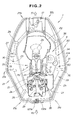
- FIG. 2 illustrates, in part in cross section, the undercover 20 and the engine 2 with the engine cover 11 as an upper cover of the outboard motor 1 removed.
- the undercover 20 consists of a left lower cover 21 and a right lower cover 31 which constitute left and right cover components.
- the left lower cover 21 and the right lower cover 31 when viewed from top have symmetrical wing-shaped cross sections with generally intermediate portions 21a and 31a bulging left and right.
- front and rear portions 21b and 21c of an upper half portion 21g of the left lower cover 21 and front and rear portions 31b and 31c of an upper half portion 31g of the right lower cover 31 extend in forward and rearward directions of the outboard motor 1.
- the front portions 21b and 31b of the left and right lower covers 21 and 31, at which the swivel case 15 and the stern bracket 16 are disposed, are hollowed in a rectangular shape toward the rear of the outboard motor 1.
- a cable support bracket 17 is provided between the front of the crankcase 2g of the engine 2 and the fronts of the left and right lower covers 21 and 31.
- An exhaust passage 2i of the cylinder head 2e is connected to the exhaust manifold 2h for communication.
- An intake passage 2j is provided in a position opposite to the exhaust passage 2i.
- An intake manifold connected to the intake passage 2j for communication is not shown in the figure.
- Reference numeral 2k denotes a sparking plug.
- FIG. 3 is an exploded perspective view of the left and right lower covers 21 and 31 and the mounting case 4.
- the left and right lower covers 21 and 31 are made from resin such as fiber-glass reinforced plastic (polypropylene).
- Rear portions 21d and 31d of the left and right lower covers 21 and 31 have rear edges 21e and 31e opposed to one another.
- the rear edges 21e and 31e are butt-joined as shown in FIG. 12, serving as joint edges.
- Lower half portions 21f and 31f of the left and right lower covers 21 and 31 are smaller in width in rearward and forward directions of the outboard motor (see FIG. 1) than the upper half portions 21g and 31g.
- a front portion 21g' of the upper half portion 21g of the left lower cover 21 is greater in vertical width than a front portion 31g' of the upper half portion 31g of the right lower cover 31.
- a front portion of a top portion 21h of the upper half portion 21g of the left lower cover 21 is flash with the top portion 21h, constituting a part of the top portion 21h.
- the bottom edge of the front portion 31g' of the upper half portion 31g is the same in height as the bottom edge of the front portion 21g' of the upper half portion 21g. However, an upper portion of the front portion 31g' of the upper half portion 31g is cut off, so that a top edge 31g-1 of the front portion 31g' is lower in height than the top edge of the front portion 2 1g'
- the left and right lower covers 21 and 31 together form an elliptical tube elongated in rearward and forward directions and vertically split in halves with a front portion hollowed sharply and with a rear portion constricted gently.
- the rear portions 21d and 31d of the left and right lower covers 21 and 31 are butt-joined at the rear edges 21e and 31e.
- opposite front edges 21i and 31i of the lower half portions 21f and 31f are butt-joined.
- the cable support bracket 17 is disposed between the front portions 21g' and 31g' of the upper half portions 21g and 31g.
- a separate cover 18 is superimposed for connection.
- Afront end portion of the separate cover 18 is formed with a notch 18a of a shape symmetrically corresponding to a notch 31j formed in a front end face of the front portion 31g.
- the notches 31j and 18g form a through hole for holding a cable with a grommet not shown.
- the mounting case 4 has a connecting opening 4d for connecting the oil pan 5a (see FIG. 1) thereto and a plurality of through holes 4c.
- An outside wall of the mounting case 4 is provided at its periphery with a flange 4e protruded outward, forming a part of the bottom of the engine space 12.
- the flange 4e is shaped to have a lower rear portion and a higher front portion, inclined downward from the front portion to the rear portion.
- a sealing member 19 is fitted onto the flange 4e of the mounting case 4, surrounding the outer periphery.
- the sealing member 19 contacts or engages part of a reinforcing frame to be described below provided on the inside surfaces of the left and right lower covers 21 and 31.
- the flange 4e of the mounting case 4 and the frame partly contacting or engaging the flange 4e constitute a partition wall for separating the engine space 12.
- the top portion 21h of the left lower cover 21 has a flange 21h-1.
- the flange 21h-1 protrudes inward, formed along the longitudinal direction of the top portion 21h.
- the top portion 21h is also integrally formed with a rib edge 21h-2 protruding upward to engage an inner edge of the cap-shaped engine cover 11 opening downward.
- Reinforcing frame members 22, 23, 25, 26, 27, 28 and 29 are integrally fixed to the inside surface of the left lower cover 21.
- Each frame member is softer than the left lower cover 21 for moldability and has a small rectangular section, for the formation of which a material of high strength such as polypropylene is selected.
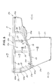
- the upper lateral frame member 22 is fixed, extending longitudinally as shown in FIGS. 5 and 7.
- the upper lateral frame member 22 is generally horizontally disposed, corresponding to the undersurface of the engine cover 11.
- the upper lateral frame member 22 has a hollow tube shape with a hollow cross section as shown in FIG. 7, a generally square shape in this embodiment.
- the upper lateral frame member 22 is fixed along the inside surface of the lower cover 21 by welding or the like, integrated with the left lower cover 21.
- a top surface 22a of the upper lateral frame member 22 is made to abut against a bottom surface 21h-3 of the top portion 21h including the flange 21h-1.
- Protruding stripes 22c, 22c are provided at the top and bottom of an outside surface 22b of the upper lateral frame member 22.
- the protruding stripes 22c, 22c abut against an inside surface 21k of the cover 21.
- the protruding stripes 22c, 22c are vibration-welded to the inside surface below the top portion 21h.
- the lower lateral frame member 23 similar to the upper lateral frame member 22 is also fixed to a vertically intermediate portion of the inside surface of the left lower cover 21 in rearward and forward directions of the outboard motor 1 (see FIG. 1).
- the lower lateral frame member 23 has a rear portion 23d lower in level, a front portion 23f higher in level, and an intermediate portion 23e inclined upward to the front.
- the lower lateral frame member 23 protrudes inward by a greater amount than the upper lateral frame member 22 as shown in FIG. 4. Specifically, the intermediate portion 23e protrudes inward by a greater amount as compared with the rear portion 23d, and the front portion 23f protrudes by a smaller amount than the rear portion 23d.
- an inner edge 23a is provided with a C-shaped hollow groove 24 opening inward.
- the hollow groove 24 is formed with a large upward inclination at the front portion 23f of the lower lateral frame member 23 while being extended rearward more gently than the rear portion 23d of the lower lateral frame member 23, corresponding to a rear portion of the mounting case 4.
- a flange 23g projecting inward is formed below the front portion 23f of the lower lateral frame member 23.
- the flange 23g supports a front undersurface of the mounting case 4.
- the lower lateral frame member 23 is fixed in the same manner as the upper lateral frame member 22. As shown in FIG. 8, a shelf protrusion 21m is provided at a holding portion on the inside surface 21k of the left lower cover 21, on which the lower lateral frame member 23 is placed. Protruding stripes 23c, 23c are provided on an outside surface 23b of the lower lateral frame member 23. The protruding stripes 23c, 23c are vibration-welded to the inside surface 21k.
- the upper and lower lateral frame members 22 and 23 and the vertical frame members 25, 26, 27 and 28 constitute a left frame assembly.
- the vertical frame members 25 to 28 are also fixed to the inside surface 21k of the left lower cover 21 by welding or the like, vertically connecting the upper and lower lateral frame members 22 and 23 for an increased frame rigidity.
- the vertical frame members 25 to 28 have hollow shapes like the upper and lower lateral frame members 22 and 23. As shown in FIG. 8, the vertical frame members 25 to 28 may be partly or at the front configured to communicate with the upper and lower lateral frame members 22 and 23.
- the embodiment shown in FIG. 8 illustrates the lateral frame members 22 and 23 and the vertical frame member 26 configured to communicate with one another.
- FIG. 8 illustrates a state in which the sealing member 19 fitted onto an engaging rim 4d protruded on the periphery of the flange 4e of the mounting case 4e is fitted into the hollow groove 24 provided in the inner edge 23a of the lower lateral frame member 23 to retain the mounting case 4.
- a sub frame member 29, an intermediate lateral frame member is provided on a rear inner portion of the left lower cover 21, extending from a generally vertically intermediate portion of the vertical frame member 25 to the rear edge 21e of the left lower cover 21.
- joint portions 122a, 129a and 123a having connecting holes 122b, 129b and 123b are integrally provided as shown in FIG. 6.
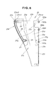
- the left lower cover 21 has, at the rear portion 21c as shown in FIG. 6, a hollow cut portion 21n opening inward to the joint edge 21e of the upper half portion 21g.
- the cut portion 21n constitutes, as shown in FIG. 15, part of a maintenance opening 50 formed by joining the left lower cover 21 and the right lower cover 31 together.
- a vertically-elongated bearing surface 21p is formed around the periphery of the hollow cut portion 21n in a surrounding manner.
- the bearing surface 21p has a plurality of mounting holes 21q.
- the right lower cover 31 has a structure substantially identical to that of the left lower cover 21 shown in FIGS. 4 to 8, and the description will be made only about the components.
- reference numeral 31h-1 denotes a flange, 31h-2 a rib edge, 32 an upper lateral frame member, 33 a lower lateral frame member, 34 a hollow groove, and 35, 36 and 38 vertical frame members.
- the upper and lower lateral frame members 32 and 33 and the vertical frame members 35, 36 and 38 constitute a right frame assembly.
- Reference numeral 39 denotes a sub frame member which is hollowed like the vertical frame members 35, 36 and 38 and is fixed to an inside surface 31k of the right lower cover 31 by welding or the like.
- Reference numeral 31e denotes a joint edge to be butt-joined to the joint edge 21e (see FIG. 3) of the left lower cover 21, and 31i a joint edge at the front.
- Reference numerals 132a, 139a and 133a denote joint portions for connecting the left lower cover 21 shown in FIG. 3 and the right lower cover 31 by bolts, configured the same as those of the left lower cover 21.
- Reference numerals 132b, 139b and 133b denote mounting holes.
- Reference numeral 31n denotes a hollow cut portion for forming the opening 50 shown in FIG. 15, 31p a bearing surface, and 31q mounting holes.
- FIG. 12 illustrates the undercover 20 with the left and right lower covers 21 and 31 joined together.
- the cable support bracket 17 is not shown for ease of understanding.
- the left and right lower covers 21 and 31 are connected by bolts by a method to be described below with the joint edges 21e and 31e at the rear of the left and right lower covers 21 and 31 butt-joined, the joint edges 21i and 31i at the front butt-joined, and the joint portions 122a, 132a, 129a, 139a, 123a and 133a superimposed back and front in the embodiment shown in the figure.
- the left and right lower covers 21 and 31 are connected in that manner to form the undercover 20.
- the lower lateral frame members 23 and 33 continuously form a flange in a loop.
- the hollow grooves 24 and 34 formed in the lower lateral frame members 23 and 33 are also formed in a loop.
- the sealing member 19 around the periphery of the mounting case 4 (see FIG. 3) is engaged with the hollow grooves 24 and 34, thereby to form a flange portion around the periphery of the mounting case 4 with the lower lateral frame members 23 and 33.
- the lower lateral frame members 23 and 33 and the mounting case 4 form the bottom of the engine space 12.
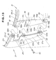
- FIGS. 13 and 14 illustrate joining the rear portions of the left and right lower covers 21 and 31.
- Bolts 40 are inserted through the respective mounting holes 122b and 132b, mounting holes 129b and 139b and mounting holes 123b and 133b of the superimposed joint portions 122a, 132a, 129a, 139a, 123a and 133a, so as to fasten and join the connecting portions 122a and 132a, connecting portions 129a and 139a and connecting portions 123a and 133a with the bolts 40.
- nuts for example, are embedded around the mounting holes 132b, 139b and 133b to screw the bolts 40 into weld nuts.
- FIG. 15 illustrates mounting a lid 41 for closing the opening 50 to the rear portion of the undercover 20.
- a vertically-elongated generally-rectangular mounting bearing surface D is formed by joining together the mounting bearing surfaces 21p and 31p formed on the rear portions of the left and right lower covers 21 and 31.
- the joint edges 21e and 31e are vertically located at the transverse center of the mounting bearing surface D, and three joints A, B and C appear.
- the mounting holes 21q and 31q are provided in the mounting bearing surface D.
- the rectangular opening 50 is formed by the hollow cut portions 2 In and 31n in an upper portion of the mounting bearing surface D. With the opening 50 opened, maintenance such as the inspection, cleaning and replacement of sparking plugs at the engine cylinder head 2e, for example, is done by inserting tools through the opening 50.
- the lid 41 closes the opening 50 and water-tightly seals the joint edge portion.
- the lid 41 is made from resin, synthetic rubber, rubber or the like.
- the lid 41 has a plane in a plate shape covering the mounting bearing surface D from the rear surface.
- a lower half portion 41a is provided at the four corners on the inner surface with a plurality of protrusions 42 to be press-fitted into the mounting holes 21q and 31q of the mounting bearing surface D for engagement.
- An upper half 41b is provided on the inner surface with a rectangular-frame-shaped sealing portion 44 having around its periphery a sealing groove 44a to be press-fitted into the opening 50 to engage the inner peripheral edge of the opening 50.
- a hinge 45 is provided between the upper half portion 41b and the lower half portion 41a of the lid 41.
- a plurality of ribs 43 of protruding stripes distanced vertically from one another is provided on the outer surface of the lower half portion 41a.
- the lid 41 is retained by press-fitting the protrusions 42 formed on the lower half portion 41a into the mounting holes 21q and 31q of the mounting bearing surface D.
- the sealing groove 44a of the sealing portion 44 engages the inner peripheral edge of the opening 50 by fitting the sealing portion 44 on the upper half portion 41b into the opening 50.
- FIG. 16 illustrates the configurations of drain passages according to the present invention.
- the embodiment shown in the figure illustrates an example of using the left and right lower lateral frame members 23 and 33 of the hollow frame members as drain passages.
- Hollow passages 61 and 71 are formed in through the left and right lower lateral frame members 23 and 33 except the joint portions 123a and 133a (see FIGS. 5 and 10), extended to portions below the joint portions 123a and 133a with opposite ends 23h and 33h butt-joined.
- Extraneous water inlets 62 and 72 are respectively formed in top surface portions 23i and 33i of the left and right lower lateral frame members 23 and 33.
- Extraneous water outlets 63 and 73 are respectively formed in bottom surface portions 23j and 33j of the frame members 23 and 33.
- the outlets and inlets 62, 63, 72, 73 communicate with the passages 61 and 71 inside the frame members 23 and 33.
- the extraneous water inlets 62 and 72 are formed in positions laterally distanced from the butt-joined ends 23h and 33h.
- the extraneous water outlets 63 and 73 are formed in positions shifted inward from the upper inlets 62 and 72, that is, positions in the vicinities of the butt-joined ends 23h and 33h.
- the upper inlets 62 and 72 and the lower outlets 63 and 73 are formed in distant positions in parallel relationships.
- the extraneous water inlets 62 and 72 are shown on the left and right of the joint portions 123a and 133a of the left and right lower lateral frame members 23 and 33.
- the extraneous water inlets 62 and 72 are shown by solid lines on the left and right of the joint portions 123a and 133a of the lower lateral frame members 23 and 33, and the outlets 63 and 73 are shown by broken lines in laterally closer portions.
- Extraneous water entering the engine space 12 thus comes down along the inner wall of the undercover 20.
- the lower lateral frame members 23 and 33 formed on the inside of the undercover 20 located in the engine space 12 are higher at the front (Fr side) and lower at the rear (Rr side) as shown in FIGS. 5 and 10. Extraneous water entering the engine space 12 thus comes, even at the forefront, for example, downward as shown by arrow 1 ⁇ and flows rearward along the slope inclined downward to the rear of the lower lateral frame members 23 and 33. The water finally collects in the direction of the lowest joint portions 123a and 133a of the lower lateral frame members 23 and 33 as shown by arrow 2 ⁇ and flows from those portions into the drain passages 61 and 71 through the inlets 62 and 72 which are provided in those portions as drainage holes.
- the top surfaces of the lower lateral frame members 23 and 33 and the top surface of the flange 4e of the mounting case 4 constitute a terrace for guiding extraneous water.
- the top surfaces of the lower lateral frame members 23 and 33 have large areas and are inclined downward to the rear as described above. Extraneous water entering the engine space 12 shown in FIG. 1 is thus effectively collected to the drain passage inlets 62 and 72.
- extraneous water entering the engine space 12 flows downward and rearward of the engine 2 as described above and flows into the drain passage 61 in the frame member 23 through the inlet 62 as shown by arrow 3 ⁇ .
- the inflow water is discharged downward of the undercover 20 through the outlet 63 displaced in parallel from the inlet 62.
- the drain passages 61 and 71 including joint portions of the lower lateral frame members 23 and 33 are slightly inclined downward at the laterally (transversely) central portion of the undercover 20 so as to lower the opposite ends 23h and 33h.
- the outlets 63 and 73 are inclined in the directions of the outlets 63 and 73, located in lower levels, so that water flowing through the inlets 62 and 72 into the drain passages 61 and 71 is smoothly discharged.
- the water entering the drain passage 71 is prevented from reaching the inlet 72 because the inlet 72 is provided in a position distanced in parallel from the outlet 73, and strikes a ceiling portion 33k of the drain passage 71. As a result, the power of the inflow water is attenuated. The water entering the passage 71 thus comes down. The extraneous water entering the drain passage 71 through the lower outlet 73 is thus prevented from entering the undercover 20, that is, the engine space 12 through the inlet 72 opening upward.
- An outboard motor (1) with an undercover (20) forming a part of an engine space (12) is provided.
- the undercover includes a left lower cover (21) and a right lower cover (31).
- the left and right lower covers are made from resin.
- a plurality of resin reinforcing frame members 22, 23, 32, 33, 25, 26, 27, 28, 35, 36, 38) is integrally fixed to inside surfaces (21k, 31k) of the left and right lower covers.
Landscapes
- Engineering & Computer Science (AREA)
- Ocean & Marine Engineering (AREA)
- Chemical & Material Sciences (AREA)
- Combustion & Propulsion (AREA)
- Mechanical Engineering (AREA)
- General Engineering & Computer Science (AREA)
- Cylinder Crankcases Of Internal Combustion Engines (AREA)
- Body Structure For Vehicles (AREA)
Abstract
Description
- The present invention relates to an outboard motor and, more particularly, an improvement in a cover structure and a drain structure in an engine space of the outboard motor.
- A body of an outboard motor is conventionally formed from an aluminum alloy. In recent years, however, a demand has grown for a new engine-housing cover made from resin for reduction in weight and cost. A combination of a synthetic resin lower cover divided generally into left and right halves and a synthetic resin upper cover demountably mounted on the lower cover, for example, has been put to practical use.
- In the cover, the engine space is made as large as possible for easy engine mounting operation and maintenance. Resin molded parts, however, have smaller rigidity as compared to aluminum alloy parts. It is especially required to provide a resin lower-half cover supporting a demountable cover with sufficient rigidity.
- For securing the rigidity of a resin cover, a cover with a ribbed configuration is presented, for example, in Japanese Patent Laid-Open Publication No. HEI-6-234393. This cover structure avoids the influence of sink marks due to ribs on the shell member consisting of resin parts.
- However, the above cover, whose ribbed configuration needs to be thickened, requires verification by trial that sink marks do not appear on the exterior of the resin cover, taking time to be commercialized and having disadvantages in quantity production and cost.
- When the ribs of the above ribbed resin cover cooperate with another body part to be fitted thereto to constitute a bottom portion constituting part of a partition wall for the engine space, the existence of webs requires another consideration to the withdrawal direction from the mold or prevents grooves from being made much deep in view of the draft for the ribs, resulting in a limited degree of freedom in design.
- Thus desired is an outboard motor with an external cover such as an engine cover of a resin cover which has secured rigidity without being made thick, facilitating the production, and having a cost benefit.
- An outboard motor allowing for maximum prevention of entering of water from the outside into the engine space which houses the engine is also known. This outboard motor is configured to quickly drain water entering from the outside.
- For drainage, a small opening has been conventionally provided, for example. Provision of such a small opening, however, contrarily leads to entering of water from outside.
- A "Drain Device for Outboard Motor" having a drain opening for discharging water entered into the engine space, and provided with a check valve for preventing entry of water from the drain opening into the engine space has been presented, for example (Japanese Patent Laid-Open Publication No. SHO-55-83696).
- This drain device, however, has a cost disadvantage due to the provision of the check valve. A drain portion formed by cutting off part of a resilient sealing member fitted onto a flange provided below the engine has a vertical passage structure with a simple opening shape. Entry of water from the outside is thus prevented only by the shutting-off function of the check valve.
- In this context, an outboard motor capable of preventing extraneous water from entering the engine space of the outboard motor and of smoothly draining entered extraneous water with a simple structure is desired.
- According to an aspect of the present invention, there is provided an outboard motor which comprises: an engine; a propeller to be driven by the engine; a drive shaft for transmitting a driving force from the engine to the propeller; casing means for supporting the engine and rotatably housing the drive shaft; and a cover forming at least a part of an engine space housing the engine, which cover comprises: a resin cover body; and a resin frame assembly integrally fixed to inside surfaces of the cover body.
- Since the cover body of the outboard motor is made from resin and the resin frame assembly is integrally fixed to the inside of the cover body, sink marks conventionally occurring in molding in which ribs are integrally provided to the inside of a resin cover body do not occur, and the need for any measures against sink marks is eliminated, and there is no influence on the appearance of the resin cover body. There is thus provided a resin cover of an outboard motor in good appearance, which uses a cover reinforcement structure for the cover while having no influence on the appearance, resulting in a good appearance of a main part constituting the appearance of the outboard motor.
- The resin cover body constituting the external cover of the outboard motor has increased rigidity with the resin frame assembly integrally provided on the inside surfaces, securing required rigidity even when an opening or the like for maintenance is made larger. The secured or increased rigidity is realized by integrating the frame assembly to the inside surfaces by welding or the like after the cover is molded, which facilitates production of a resin cover having high rigidity and providing good appearance to an outboard motor, allowing reduction in weight and providing a cost benefit.
- Preferably, the cover body preferably has holding portions on the inside surfaces for fixing the frame assembly thereto, so as to facilitate the fixing of the resin frame assembly and eliminate any influence on the appearance of the resin cover.
- The cover body preferably comprises a lower cover and an upper cover demountably mounted on the lower cover, which lower cover has flanges serving both as seals for the upper cover and as fixing portions for the frame assembly. Thus the sealing and fixing functions can be performed by a single part, resulting in a simplified structure of fixing portions of the frame assembly and a simplified structure of the cover body provided with the reinforcing frame assembly.
- Frame members constituting parts of the frame assembly preferably function as a flange at the bottom periphery of the engine space. A single component can thus have multi-functions, resulting in a simplified structure.
- It is desired that frame members constituting parts of the frame assembly contact or engage a peripheral portion of a mounting case substantially constituting the bottom of the engine space to thereby constitute the bottom of the engine space and defining the engine space within the exterior cover. Thus no additional components for separating the engine space are required. The multifunctional components and the contact or engagement of the periphery of the mounting case to or with the frame members allow the separation of the inside of the cover body above and below to define the engine space, resulting in a further simplified structure and facilitated production.
- The frame assembly provided on the inside of the cover body preferably comprises lateral frame members provided in upper and lower positions and extending in a rearward-and-forward direction, and a plurality of vertical frame members connecting the upper and lower lateral frame members. The rigidity of the frame assembly is thus increased, resulting in a resin cover structure of high rigidity even with the resin frame assembly integrally fixed to the resin cover.
- Desirably, the cover of the outboard motor has a cover body forming the engine space housing the engine, and drain passages extending from the inside of the cover body to the outside of the cover body; which drain passages have inlets facing the engine space and outlets facing the outside of the engine space; which inlets and outlets are provided in positions distanced vertically and also distanced laterally of the outboard motor.
- The external water inlets and outlets are thus in a labyrinthine arrangement in which water entering in the direction opposite to the drainage direction, that is, external water entering through the outlets into the drain passages strikes the ceilings of the drain passages because the inlets are not located immediately above the outlets, attenuated in energy by change of direction, and hardly enters the engine space. The simple structure can thus prevent the entering of external water into the engine space of the outboard motor and drain entering external water smoothly.
- The cover body may be a resin cover and has hollow frame members integrally fixed to the inside surfaces of the cover body after the cover body is molded; and the drain passages are partly formed in hollow portions of the frame members. Making the reinforcing frame members provided on the inside of the resin cover hollow and using the hollow portions as drain passages facilitate the formation of drain passages, allowing the formation of drain passages in the engine space using the reinforcing members also serving as drains. The inlets and outlets may be formed in the tops and bottoms of the hollow frame members in positions shifted in parallel relationships, allowing the formation of drain passages having a simple structure easily produced and good functions.
- The cover body may be an undercover provided below an engine cover, defining at least a part of the engine space. In other words, the cover of this invention comprises an undercover constituting an external cover of the outboard motor, disposed below an engine cover. The hollow frame members are provided to the undercover, thereby to form the drain passages. Extraneous water entered the engine space is thus discharged from a lower portion of the undercover.
- Preferred embodiments of the present invention will be described in detail below, by way of example only, with reference to the accompanying drawings, in which:
- FIG. 1 is a side view, partly in cross section, of an outboard motor according to the present invention;
- FIG. 2 is a plan view of the outboard motor with an undercover and an engine shown in cross section with an engine cover removed;
- FIG. 3 is an exploded perspective view illustrating the undercover consisting of a left lower cover and a right lower cover and a mounting case;
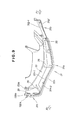
- FIG. 4 is a plan view of the left lower cover of FIG. 3;
- FIG. 5 is a side view as seen from the inside of the left lower cover shown in FIG. 3;
- FIG. 6 is a partial sectional view as seen from the rear of the left lower cover shown in FIG. 3;
- FIG. 7 is a cross-sectional view taken along line 7-7 of FIG. 5, illustrating a fixed state of an upper lateral frame member;
- FIG. 8 is a cross-sectional view taken along line 8-8 of FIG. 5, illustrating a fixed state of a lower lateral frame member;
- FIG. 9 is a plan view of the right lower cover of FIG. 3;
- FIG. 10 is a side view from inside of the right lower cover of FIG. 3;
- FIG. 11 is a partial sectional view from the rear of the right lower cover shown in FIG. 3;
- FIG. 12 is a top plan view of the left and right lower covers joined together;
- FIG. 13 is a perspective view illustrating joining rear portions of the left and right lower covers;
- FIG. 14 is a plan view illustrating in enlargement the rear of the undercover with the left and right lower covers joined together;
- FIG. 15 is a perspective view of the rear of the undercover, illustrating mounting a lid for closing an opening; and
- FIG. 16 is a cross-sectional view illustrating left and right lower lateral frame members provided with drain passages.
-
- In FIG. 1, reference character Fr represents forward in a direction of propulsion and Rr rearward in a direction of propulsion.
- An
outboard motor 1 has casing means for supporting an engine and covering means for covering the engine, defining an engine space. - An
engine 2 used in theoutboard motor 1 in this embodiment is a vertical engine with acrank shaft 2a vertically oriented, a multi-cylinder engine having a plurality ofcylinders 2b arranged one above the other with their axis lines horizontally oriented. - A
piston 2c is fitted into each of thecylinders 2b of theengine 2. Acylinder block 2d is disposed in a middle region of theoutboard motor 1 in rearward and forward directions. - At the rear of the
cylinder block 2d, acylinder head 2e is provided, at the rear of which acylinder head cover 2f is provided. A crankcase 2g is disposed forward of thecylinder block 2d. - The
engine 2 is supported at the bottom on a mountingcase 4 via apump body 3. Anoil case 5 is provided at the underside of the mountingcase 4, hanging down. In other words, theoil case 5 is fixed to the undersurface of the mountingcase 4, extending downward. - An
exhaust passage 5b is extended downward near anoil pan 5a of theoil case 5. Theexhaust passage 5b is connected to a connectinghole 5b formed in the mountingcase 4b for communication. Reference numeral 4a denotes a water jacket. - Exhaust air is guided from combustion chambers of the
engine 2 through thecylinder head 2e, anexhaust manifold 2h (see FIG. 2), anexhaust guide 6, anexhaust passage 4b in the mountingcase 4 and theexhaust passage 5b to the inside of anextension case 13 to be described below. - A
suction tube 3b extends downward from the undersurface of thepump body 3 into theoil pan 5a, having astrainer 3a at the lower end located in a lower portion inside theoil pan 5a. - The
crankshaft 2a is located in a forward portion of the entireoutboard motor 1, the lower end of which vertically passes through thepump body 3 and connected to the upper end of adrive shaft 7 provided vertically. - The
drive shaft 7 passes through a throughhole 4c provided in a forward portion of the mountingcase 4, passing between theoil pan 5a and aperipheral wall 5c of theoil case 5 and extending downward for driving anoutput shaft 9a via atransmission mechanism 8. - A
propeller 9 is connected to theoutput shaft 9a. Theengine 2 drives thedrive shaft 7 to drive thepropeller 9 via thetransmission mechanism 8, thereby to provide theoutboard motor 1 with a propulsion power. - A covering means 10 constituting a part of the shell member of the
outboard motor 1 covers upper, side and lower portions of theengine 2. The covering means 10 consists of a cap-shapedengine cover 11 oriented downward for covering an upper portion of theengine 2 above a vertically intermediate portion thereof, and an undercover 20 for enclosing a lower portion of theengine 2, thepump body 3, the mountingcase 4 and theoil case 5. - The undercover 20, as shown in FIG. 3, consists of a left
lower cover 21 and a rightlower cover 31 as left and right cover members. - The
engine space 12 is defined by theengine cover 11 and an upper portion of the undercover 20. In other words, theengine space 12 is formed by an upper portion separated from a lower portion by the mountingcase 4 as will be described below. Theengine space 12 is located in an upper portion of theoutboard motor 1. The mountingcase 4 corresponds to the bottom of theengine space 12 as will be described below. - As described above, the
oil case 5 is fixed to the underside of the mountingcase 4. Theextension case 13 is mounted to the underside of theoil case 5. Theextension case 13 is made from an aluminum alloy. A gear case 14 is connected below theextension case 13. The gear case 14 houses a lower portion of thedrive shaft 7, thetransmission mechanism 8 and theoutput shaft 9a. - The undercover 20 externally covers the junction between the mounting
case 4 and theoil case 5. A lower portion of the undercover 20 extends downward. - The
outboard motor 1 swings laterally about aswivel shaft 15a. Theswivel shaft 15a is vertically provided between a forward portion of the undercover 20 and a front portion of theextension case 13. Theoutboard motor 1 also swings vertically about atilt shaft 16a. Thetilt shaft 16a is provided at astern bracket 16 connected to aswivel case 15. - The mounting
case 4,oil case 5,extension case 13 and gear case 14 constitute casing means. - FIG. 2 illustrates, in part in cross section, the undercover 20 and the
engine 2 with theengine cover 11 as an upper cover of theoutboard motor 1 removed. - The undercover 20 consists of a left
lower cover 21 and a rightlower cover 31 which constitute left and right cover components. The leftlower cover 21 and the rightlower cover 31 when viewed from top have symmetrical wing-shaped cross sections with generallyintermediate portions - As shown in FIG. 3, front and
rear portions upper half portion 21g of the leftlower cover 21 and front andrear portions upper half portion 31g of the rightlower cover 31 extend in forward and rearward directions of theoutboard motor 1. Thefront portions swivel case 15 and thestern bracket 16 are disposed, are hollowed in a rectangular shape toward the rear of theoutboard motor 1. - As shown in FIG. 2, a
cable support bracket 17 is provided between the front of the crankcase 2g of theengine 2 and the fronts of the left and right lower covers 21 and 31. - An
exhaust passage 2i of thecylinder head 2e is connected to theexhaust manifold 2h for communication. Anintake passage 2j is provided in a position opposite to theexhaust passage 2i. An intake manifold connected to theintake passage 2j for communication is not shown in the figure.Reference numeral 2k denotes a sparking plug. - FIG. 3 is an exploded perspective view of the left and right lower covers 21 and 31 and the mounting
case 4. - The left and right lower covers 21 and 31 are made from resin such as fiber-glass reinforced plastic (polypropylene).
-
Rear portions rear edges rear edges -
Lower half portions upper half portions front portion 21g' of theupper half portion 21g of the leftlower cover 21 is greater in vertical width than afront portion 31g' of theupper half portion 31g of the rightlower cover 31. A front portion of atop portion 21h of theupper half portion 21g of the leftlower cover 21 is flash with thetop portion 21h, constituting a part of thetop portion 21h. - The bottom edge of the
front portion 31g' of theupper half portion 31g is the same in height as the bottom edge of thefront portion 21g' of theupper half portion 21g. However, an upper portion of thefront portion 31g' of theupper half portion 31g is cut off, so that atop edge 31g-1 of thefront portion 31g' is lower in height than the top edge of thefront portion 2 1g' - The left and right lower covers 21 and 31 together form an elliptical tube elongated in rearward and forward directions and vertically split in halves with a front portion hollowed sharply and with a rear portion constricted gently. The
rear portions rear edges front edges lower half portions - With the left and right lower covers 21 and 31 joined together, the
cable support bracket 17 is disposed between thefront portions 21g' and 31g' of theupper half portions - On the
front portion 31g' as a protrusion protruded forward of the rightlower cover 31, aseparate cover 18 is superimposed for connection. Afront end portion of theseparate cover 18 is formed with a notch 18a of a shape symmetrically corresponding to anotch 31j formed in a front end face of thefront portion 31g. Thenotches 31j and 18g form a through hole for holding a cable with a grommet not shown. - The mounting
case 4 has a connectingopening 4d for connecting theoil pan 5a (see FIG. 1) thereto and a plurality of throughholes 4c. - An outside wall of the mounting
case 4 is provided at its periphery with aflange 4e protruded outward, forming a part of the bottom of theengine space 12. Theflange 4e is shaped to have a lower rear portion and a higher front portion, inclined downward from the front portion to the rear portion. - A sealing
member 19 is fitted onto theflange 4e of the mountingcase 4, surrounding the outer periphery. The sealingmember 19 contacts or engages part of a reinforcing frame to be described below provided on the inside surfaces of the left and right lower covers 21 and 31. - The
flange 4e of the mountingcase 4 and the frame partly contacting or engaging theflange 4e constitute a partition wall for separating theengine space 12. - Now the configuration of the left
lower cover 21 will be described with reference to FIGS. 4 to 8. - The
top portion 21h of the leftlower cover 21 has aflange 21h-1. Theflange 21h-1 protrudes inward, formed along the longitudinal direction of thetop portion 21h. Thetop portion 21h is also integrally formed with arib edge 21h-2 protruding upward to engage an inner edge of the cap-shapedengine cover 11 opening downward. - Reinforcing
frame members lower cover 21. Each frame member is softer than the leftlower cover 21 for moldability and has a small rectangular section, for the formation of which a material of high strength such as polypropylene is selected. - To the underside of the
flange 21h-1 on the inside surface of the leftlower cover 21, the upperlateral frame member 22 is fixed, extending longitudinally as shown in FIGS. 5 and 7. - The upper
lateral frame member 22 is generally horizontally disposed, corresponding to the undersurface of theengine cover 11. The upperlateral frame member 22 has a hollow tube shape with a hollow cross section as shown in FIG. 7, a generally square shape in this embodiment. - After the left
lower cover 21 is molded, the upperlateral frame member 22 is fixed along the inside surface of thelower cover 21 by welding or the like, integrated with the leftlower cover 21. - An exemplary fixing method of the upper
lateral frame member 22 will be described with reference to FIG. 7. Atop surface 22a of the upperlateral frame member 22 is made to abut against abottom surface 21h-3 of thetop portion 21h including theflange 21h-1. - Protruding
stripes outside surface 22b of the upperlateral frame member 22. The protrudingstripes inside surface 21k of thecover 21. The protrudingstripes top portion 21h. - As shown in FIG. 5, the lower
lateral frame member 23 similar to the upperlateral frame member 22 is also fixed to a vertically intermediate portion of the inside surface of the leftlower cover 21 in rearward and forward directions of the outboard motor 1 (see FIG. 1). - The lower
lateral frame member 23 has arear portion 23d lower in level, afront portion 23f higher in level, and anintermediate portion 23e inclined upward to the front. - The lower
lateral frame member 23 protrudes inward by a greater amount than the upperlateral frame member 22 as shown in FIG. 4. Specifically, theintermediate portion 23e protrudes inward by a greater amount as compared with therear portion 23d, and thefront portion 23f protrudes by a smaller amount than therear portion 23d. - It is important in the lower
lateral frame member 23 that, as shown in FIGS. 5, 6 and 8, aninner edge 23a is provided with a C-shapedhollow groove 24 opening inward. - The
hollow groove 24 is formed with a large upward inclination at thefront portion 23f of the lowerlateral frame member 23 while being extended rearward more gently than therear portion 23d of the lowerlateral frame member 23, corresponding to a rear portion of the mountingcase 4. - A flange 23g projecting inward is formed below the
front portion 23f of the lowerlateral frame member 23. The flange 23g supports a front undersurface of the mountingcase 4. - The lower
lateral frame member 23 is fixed in the same manner as the upperlateral frame member 22. As shown in FIG. 8, ashelf protrusion 21m is provided at a holding portion on theinside surface 21k of the leftlower cover 21, on which the lowerlateral frame member 23 is placed. Protrudingstripes outside surface 23b of the lowerlateral frame member 23. The protrudingstripes inside surface 21k. - Between the rear portions, intermediate portions and front portions of the upper and lower
lateral frame members vertical frame members lateral frame members vertical frame members - The
vertical frame members 25 to 28 are also fixed to theinside surface 21k of the leftlower cover 21 by welding or the like, vertically connecting the upper and lowerlateral frame members vertical frame members 25 to 28 have hollow shapes like the upper and lowerlateral frame members vertical frame members 25 to 28 may be partly or at the front configured to communicate with the upper and lowerlateral frame members lateral frame members vertical frame member 26 configured to communicate with one another. - FIG. 8 illustrates a state in which the sealing
member 19 fitted onto anengaging rim 4d protruded on the periphery of theflange 4e of the mountingcase 4e is fitted into thehollow groove 24 provided in theinner edge 23a of the lowerlateral frame member 23 to retain the mountingcase 4. - As shown in FIGS. 3 and 5, a
sub frame member 29, an intermediate lateral frame member, is provided on a rear inner portion of the leftlower cover 21, extending from a generally vertically intermediate portion of thevertical frame member 25 to therear edge 21e of the leftlower cover 21. - At the rear ends of the upper
lateral frame member 22, lateral intermediatesub frame member 29 and lowerlateral frame member 23,joint portions holes - The left
lower cover 21 has, at therear portion 21c as shown in FIG. 6, ahollow cut portion 21n opening inward to thejoint edge 21e of theupper half portion 21g. Thecut portion 21n constitutes, as shown in FIG. 15, part of amaintenance opening 50 formed by joining the leftlower cover 21 and the rightlower cover 31 together. A vertically-elongatedbearing surface 21p is formed around the periphery of thehollow cut portion 21n in a surrounding manner. The bearingsurface 21p has a plurality of mounting holes 21q. - Now, the configuration of the right
lower cover 31 will be described with reference to FIGS. 9 to 11. - The right
lower cover 31 has a structure substantially identical to that of the leftlower cover 21 shown in FIGS. 4 to 8, and the description will be made only about the components. - In those figures,
reference numeral 31h-1 denotes a flange, 31h-2 a rib edge, 32 an upper lateral frame member, 33 a lower lateral frame member, 34 a hollow groove, and 35, 36 and 38 vertical frame members. The upper and lowerlateral frame members vertical frame members Reference numeral 39 denotes a sub frame member which is hollowed like thevertical frame members inside surface 31k of the rightlower cover 31 by welding or the like. -
Reference numeral 31e denotes a joint edge to be butt-joined to thejoint edge 21e (see FIG. 3) of the leftlower cover -
Reference numerals lower cover 21 shown in FIG. 3 and the rightlower cover 31 by bolts, configured the same as those of the leftlower cover 21.Reference numerals Reference numeral 31n denotes a hollow cut portion for forming theopening 50 shown in FIG. 15, 31p a bearing surface, and 31q mounting holes. - FIG. 12 illustrates the undercover 20 with the left and right lower covers 21 and 31 joined together. In the figure, the
cable support bracket 17 is not shown for ease of understanding. - The left and right lower covers 21 and 31 are connected by bolts by a method to be described below with the
joint edges joint edges joint portions - The left and right lower covers 21 and 31 are connected in that manner to form the undercover 20. The lower
lateral frame members hollow grooves lateral frame members member 19 around the periphery of the mounting case 4 (see FIG. 3) is engaged with thehollow grooves case 4 with the lowerlateral frame members lateral frame members case 4 form the bottom of theengine space 12. - FIGS. 13 and 14 illustrate joining the rear portions of the left and right lower covers 21 and 31.
- To join the rear portions of the left and right lower covers 21 and 31 by butt-joining the
joint edges joint portions lateral frame member 22, upperlateral frame member 32,sub frame member 29,sub frame member 39, lowerlateral frame member 23 and lowerlateral frame member 33, respectively, are superimposed back and front with thejoint edges -
Bolts 40 are inserted through the respective mountingholes holes holes joint portions portions portions portions bolts 40. - For the bolt joining, nuts, for example, are embedded around the mounting
holes bolts 40 into weld nuts. - FIG. 15 illustrates mounting a
lid 41 for closing theopening 50 to the rear portion of the undercover 20. - On a
rear surface 20a of the undercover 20, a vertically-elongated generally-rectangular mounting bearing surface D is formed by joining together the mountingbearing surfaces joint edges - The
rectangular opening 50 is formed by thehollow cut portions 2 In and 31n in an upper portion of the mounting bearing surface D. With theopening 50 opened, maintenance such as the inspection, cleaning and replacement of sparking plugs at theengine cylinder head 2e, for example, is done by inserting tools through theopening 50. - In FIG. 15, the
lid 41 closes theopening 50 and water-tightly seals the joint edge portion. Thelid 41 is made from resin, synthetic rubber, rubber or the like. Thelid 41 has a plane in a plate shape covering the mounting bearing surface D from the rear surface. Alower half portion 41a is provided at the four corners on the inner surface with a plurality ofprotrusions 42 to be press-fitted into the mounting holes 21q and 31q of the mounting bearing surface D for engagement. Anupper half 41b is provided on the inner surface with a rectangular-frame-shapedsealing portion 44 having around its periphery a sealinggroove 44a to be press-fitted into theopening 50 to engage the inner peripheral edge of theopening 50. - A
hinge 45 is provided between theupper half portion 41b and thelower half portion 41a of thelid 41. A plurality ofribs 43 of protruding stripes distanced vertically from one another is provided on the outer surface of thelower half portion 41a. - The
lid 41 is retained by press-fitting theprotrusions 42 formed on thelower half portion 41a into the mounting holes 21q and 31q of the mounting bearing surface D. The sealinggroove 44a of the sealingportion 44 engages the inner peripheral edge of theopening 50 by fitting the sealingportion 44 on theupper half portion 41b into theopening 50. - Pulling the
upper half portion 41b of thelid 41 rearward disengages the sealingportion 44 from theopening 50. Theupper half portion 41b bends and tilts rearward on thehinge 45, allowing access to theopening 50. By contrast, raising theupper half portion 41b to press-fit the sealingportion 44 into theopening 50 closes theopening 50. - FIG. 16 illustrates the configurations of drain passages according to the present invention.
- The embodiment shown in the figure illustrates an example of using the left and right lower
lateral frame members -
Hollow passages lateral frame members joint portions joint portions opposite ends -
Extraneous water inlets top surface portions lateral frame members Extraneous water outlets bottom surface portions frame members inlets passages frame members - The
extraneous water inlets extraneous water outlets upper inlets upper inlets lower outlets - In FIG. 12, the
extraneous water inlets joint portions lateral frame members extraneous water inlets joint portions lateral frame members outlets - Extraneous water entering the
engine space 12 thus comes down along the inner wall of the undercover 20. - The lower
lateral frame members engine space 12 are higher at the front (Fr side) and lower at the rear (Rr side) as shown in FIGS. 5 and 10. Extraneous water entering theengine space 12 thus comes, even at the forefront, for example, downward as shown byarrow 1 ○and flows rearward along the slope inclined downward to the rear of the lowerlateral frame members joint portions lateral frame members arrow 2 ○and flows from those portions into thedrain passages inlets - As shown in FIG. 2, the top surfaces of the lower
lateral frame members flange 4e of the mountingcase 4 constitute a terrace for guiding extraneous water. As indicated byreference numerals lateral frame members engine space 12 shown in FIG. 1 is thus effectively collected to thedrain passage inlets - As shown in FIG. 16, extraneous water entering the
engine space 12 flows downward and rearward of theengine 2 as described above and flows into thedrain passage 61 in theframe member 23 through theinlet 62 as shown byarrow 3 ○. - The inflow water is discharged downward of the undercover 20 through the
outlet 63 displaced in parallel from theinlet 62. As shown in the figure, thedrain passages lateral frame members outlets outlets inlets drain passages - With FIG. 16, the water collection and drainage have been described with respect to the
right drain passage 61. The same holds true for theleft drain passage 71. - As shown in the
left drain passage 71 in FIG. 16, extraneous water entering from below theoutboard motor 1 due to waves enters through theoutlet 73 opening downward into thedrain passage 71 as shown byarrow 5 ○. - The water entering the
drain passage 71 is prevented from reaching theinlet 72 because theinlet 72 is provided in a position distanced in parallel from theoutlet 73, and strikes aceiling portion 33k of thedrain passage 71. As a result, the power of the inflow water is attenuated. The water entering thepassage 71 thus comes down. The extraneous water entering thedrain passage 71 through thelower outlet 73 is thus prevented from entering the undercover 20, that is, theengine space 12 through theinlet 72 opening upward. - The description has been made with the figure about the entering of extraneous water through the
left outlet 73. The same holds true for the entering of extraneous water through theright outlet 63. - An outboard motor (1) with an undercover (20) forming a part of an engine space (12) is provided. The undercover includes a left lower cover (21) and a right lower cover (31). The left and right lower covers are made from resin. To prevent the undercover from affecting the appearance, a plurality of resin reinforcing frame members (22, 23, 32, 33, 25, 26, 27, 28, 35, 36, 38) is integrally fixed to inside surfaces (21k, 31k) of the left and right lower covers.
Claims (9)
- An outboard motor comprising:said cover comprising:an engine (2);a propeller (9) to be driven by said engine;a drive shaft (7) for transmitting a driving force from said engine to said propeller;casing means (4, 5, 13, 14) for supporting said engine and rotatably housing said drive shaft; anda cover forming at least a part of an engine space (12) housing said engine,a resin cover body; anda resin frame assembly integrally fixed to inside surfaces (21k, 31k) of said cover body.
- The outboard motor of claim 1, wherein said cover body has holding portions on said inside surfaces for fixing said frame assembly thereto.
- The outboard motor of claim 2, wherein said cover body comprises a lower cover (20) and an upper cover (11) demountably mounted on said lower cover, said lower cover having flanges (21h-1, 31h-1) serving both as seals for said upper cover and as fixing portions for said frame assembly.
- The outboard motor of claim 1, wherein frame members (23, 33) constituting parts of said frame assembly function as a flange at a bottom periphery of said engine space (12).
- The outboard motor of claim 1, wherein frame members (23, 33) constituting parts of said frame assembly contact or engage a peripheral portion (4e) of a mounting case (4) substantially constituting a bottom of said engine space (12), thereby constituting the bottom of said engine space and defining said engine space within said cover body.
- The outboard motor of claim 1, wherein said frame assembly provided on the inside of said cover body comprises lateral frame members (22, 23, 32, 33) provided in upper and lower positions and extending in a rearward-and-forward direction, and a plurality of vertical frame members (25, 26, 27, 28, 35, 36, 38) connecting said upper and lower lateral frame members.
- The outboard motor of claim 1, wherein said cover has a cover body forming said engine space housing said engine, and drain passages (61, 71) extending from the inside of said cover body to the outside of said cover body;
said drain passages having inlets (62, 72) facing said engine space and outlets (63, 73) facing the outside of said engine space;
said inlets and outlets being provided in positions distanced vertically and also distanced laterally of said outboard motor (1). - The outboard motor of claim 7, wherein said cover is a resin cover body and has hollow frame members (23, 33) integrally fixed to the inside of said cover body after said cover body is molded; and
said drain passages are partly formed in hollow portions of said frame members. - The outboard motor of claim 7, wherein said cover body is an undercover (20) provided below an engine cover (11), defining at least a part of said engine space (12).
Applications Claiming Priority (4)
| Application Number | Priority Date | Filing Date | Title |
|---|---|---|---|
| JP2002210014 | 2002-07-18 | ||
| JP2002210014A JP2004050936A (en) | 2002-07-18 | 2002-07-18 | Drainage structure of engine room of outboard motor |
| JP2002209990 | 2002-07-18 | ||
| JP2002209990A JP2004050934A (en) | 2002-07-18 | 2002-07-18 | Outboard motor cover structure |
Publications (2)
| Publication Number | Publication Date |
|---|---|
| EP1382814A1 true EP1382814A1 (en) | 2004-01-21 |
| EP1382814B1 EP1382814B1 (en) | 2007-09-19 |
Family
ID=29782064
Family Applications (1)
| Application Number | Title | Priority Date | Filing Date |
|---|---|---|---|
| EP03015385A Expired - Lifetime EP1382814B1 (en) | 2002-07-18 | 2003-07-08 | Outboard motor |
Country Status (6)
| Country | Link |
|---|---|
| US (1) | US6878022B2 (en) |
| EP (1) | EP1382814B1 (en) |
| CN (1) | CN1290741C (en) |
| CA (1) | CA2434563C (en) |
| DE (1) | DE60316386T2 (en) |
| ES (1) | ES2294220T3 (en) |
Cited By (2)
| Publication number | Priority date | Publication date | Assignee | Title |
|---|---|---|---|---|
| WO2007023925A3 (en) * | 2005-08-22 | 2007-07-12 | Honda Motor Co Ltd | Outboard engine |
| IT202200020121A1 (en) * | 2022-09-30 | 2024-03-30 | Huracan Marine Srl | Lightweight Outboard Marine Engine |
Families Citing this family (5)
| Publication number | Priority date | Publication date | Assignee | Title |
|---|---|---|---|---|
| JP2006182219A (en) * | 2004-12-28 | 2006-07-13 | Yamaha Marine Co Ltd | Top cowl of outboard motor and casting mold for manufacturing the same |
| CA2584386C (en) * | 2006-05-01 | 2013-11-19 | Honda Motor Co., Ltd. | Outboard engine unit |
| US9073616B1 (en) | 2010-10-29 | 2015-07-07 | Brp Us Inc. | Marine engine cowling |
| US11046409B2 (en) | 2018-12-21 | 2021-06-29 | Brp Us Inc. | Marine outboard engine cowling |
| JP7563222B2 (en) * | 2021-02-16 | 2024-10-08 | スズキ株式会社 | Cover Structure |
Citations (4)
| Publication number | Priority date | Publication date | Assignee | Title |
|---|---|---|---|---|
| JPS5583696A (en) | 1978-12-15 | 1980-06-24 | Sanshin Ind Co Ltd | Drain device for outboard machine |
| US5069643A (en) * | 1990-05-18 | 1991-12-03 | Outboard Marine Corporation | Molded lower motor cover |
| US5360358A (en) * | 1993-05-21 | 1994-11-01 | Outboard Marine Corporation | Hidden lower motor cover attachment means |
| US20010008818A1 (en) * | 2000-01-17 | 2001-07-19 | Honda Giken Kogyo Kabushiki Kaisha | Outboard engine system |
Family Cites Families (3)
| Publication number | Priority date | Publication date | Assignee | Title |
|---|---|---|---|---|
| US3358668A (en) * | 1965-08-03 | 1967-12-19 | Kiekhaefer Corp | Outboard motor cowl mounting |
| US5487687A (en) * | 1994-07-18 | 1996-01-30 | Brunswick Corporation | Midsection and cowl assembly for an outboard marine drive |
| JPH10175594A (en) * | 1996-12-19 | 1998-06-30 | Honda Motor Co Ltd | Outboard motor |
-
2003
- 2003-07-07 CA CA002434563A patent/CA2434563C/en not_active Expired - Fee Related
- 2003-07-08 ES ES03015385T patent/ES2294220T3/en not_active Expired - Lifetime
- 2003-07-08 DE DE60316386T patent/DE60316386T2/en not_active Expired - Lifetime
- 2003-07-08 EP EP03015385A patent/EP1382814B1/en not_active Expired - Lifetime
- 2003-07-09 US US10/616,423 patent/US6878022B2/en not_active Expired - Fee Related
- 2003-07-18 CN CN03133240.4A patent/CN1290741C/en not_active Expired - Fee Related
Patent Citations (5)
| Publication number | Priority date | Publication date | Assignee | Title |
|---|---|---|---|---|
| JPS5583696A (en) | 1978-12-15 | 1980-06-24 | Sanshin Ind Co Ltd | Drain device for outboard machine |
| US5069643A (en) * | 1990-05-18 | 1991-12-03 | Outboard Marine Corporation | Molded lower motor cover |
| JPH06234393A (en) | 1990-05-18 | 1994-08-23 | Outboard Marine Corp | Die molded lower engine cover |
| US5360358A (en) * | 1993-05-21 | 1994-11-01 | Outboard Marine Corporation | Hidden lower motor cover attachment means |
| US20010008818A1 (en) * | 2000-01-17 | 2001-07-19 | Honda Giken Kogyo Kabushiki Kaisha | Outboard engine system |
Non-Patent Citations (1)
| Title |
|---|
| PATENT ABSTRACTS OF JAPAN vol. 2000, no. 17 5 June 2001 (2001-06-05) * |
Cited By (2)
| Publication number | Priority date | Publication date | Assignee | Title |
|---|---|---|---|---|
| WO2007023925A3 (en) * | 2005-08-22 | 2007-07-12 | Honda Motor Co Ltd | Outboard engine |
| IT202200020121A1 (en) * | 2022-09-30 | 2024-03-30 | Huracan Marine Srl | Lightweight Outboard Marine Engine |
Also Published As
| Publication number | Publication date |
|---|---|
| US6878022B2 (en) | 2005-04-12 |
| EP1382814B1 (en) | 2007-09-19 |
| DE60316386T2 (en) | 2008-01-10 |
| CN1475403A (en) | 2004-02-18 |
| US20040014379A1 (en) | 2004-01-22 |
| CN1290741C (en) | 2006-12-20 |
| CA2434563A1 (en) | 2004-01-18 |
| CA2434563C (en) | 2007-03-27 |
| ES2294220T3 (en) | 2008-04-01 |
| DE60316386D1 (en) | 2007-10-31 |
Similar Documents
| Publication | Publication Date | Title |
|---|---|---|
| KR101576298B1 (en) | Oil pan | |
| JP3907082B2 (en) | Outboard motor | |
| US7210972B2 (en) | Outboard engine | |
| EP1382814B1 (en) | Outboard motor | |
| EP1382815B1 (en) | Cover joining structure for outboard engine unit | |
| JP2005125827A (en) | Scooter type motorcycle | |
| JP3957674B2 (en) | Oil pan structure | |
| US7131420B2 (en) | Power transmission system cover for engine | |
| EP1382525B1 (en) | Outboard motor | |
| JP3665122B2 (en) | Oil pan for internal combustion engine | |
| US7021979B2 (en) | Outboard motor | |
| JP3741799B2 (en) | Oil pump mounting device for engine | |
| US20040226533A1 (en) | Outboard motor having seal structure for exhaust release pipe | |
| JP2004050936A (en) | Drainage structure of engine room of outboard motor | |
| JP3597984B2 (en) | Structure of oil pan in slant type internal combustion engine | |
| JP4269027B2 (en) | Outboard motor intake system | |
| JPS63154845A (en) | Oil pan for engine | |
| JP5227821B2 (en) | Oil pan | |
| JP2012184691A (en) | Throttle device | |
| JP5281910B2 (en) | Oil pan | |
| JP2004050934A (en) | Outboard motor cover structure | |
| JP7079720B2 (en) | Internal combustion engine | |
| JPH10218091A (en) | Outboard motor seal structure | |
| JP2000230412A (en) | Crankcase ventilation passage | |
| JP5281909B2 (en) | Oil pan |
Legal Events
| Date | Code | Title | Description |
|---|---|---|---|
| PUAI | Public reference made under article 153(3) epc to a published international application that has entered the european phase |
Free format text: ORIGINAL CODE: 0009012 |
|
| AK | Designated contracting states |
Kind code of ref document: A1 Designated state(s): AT BE BG CH CY CZ DE DK EE ES FI FR GB GR HU IE IT LI LU MC NL PT RO SE SI SK TR |
|
| AX | Request for extension of the european patent |
Extension state: AL LT LV MK |
|
| 17P | Request for examination filed |
Effective date: 20040227 |
|
| AKX | Designation fees paid |
Designated state(s): DE ES FR GB |
|
| 17Q | First examination report despatched |
Effective date: 20061207 |
|
| GRAP | Despatch of communication of intention to grant a patent |
Free format text: ORIGINAL CODE: EPIDOSNIGR1 |
|
| GRAS | Grant fee paid |
Free format text: ORIGINAL CODE: EPIDOSNIGR3 |
|
| GRAA | (expected) grant |
Free format text: ORIGINAL CODE: 0009210 |
|
| AK | Designated contracting states |
Kind code of ref document: B1 Designated state(s): DE ES FR GB |
|
| REG | Reference to a national code |
Ref country code: GB Ref legal event code: FG4D |
|
| REF | Corresponds to: |
Ref document number: 60316386 Country of ref document: DE Date of ref document: 20071031 Kind code of ref document: P |
|
| REG | Reference to a national code |
Ref country code: ES Ref legal event code: FG2A Ref document number: 2294220 Country of ref document: ES Kind code of ref document: T3 |
|
| ET | Fr: translation filed | ||
| PLBE | No opposition filed within time limit |
Free format text: ORIGINAL CODE: 0009261 |
|
| STAA | Information on the status of an ep patent application or granted ep patent |
Free format text: STATUS: NO OPPOSITION FILED WITHIN TIME LIMIT |
|
| 26N | No opposition filed |
Effective date: 20080620 |
|
| PGFP | Annual fee paid to national office [announced via postgrant information from national office to epo] |
Ref country code: ES Payment date: 20100813 Year of fee payment: 8 |
|
| PGFP | Annual fee paid to national office [announced via postgrant information from national office to epo] |
Ref country code: DE Payment date: 20100630 Year of fee payment: 8 Ref country code: FR Payment date: 20100805 Year of fee payment: 8 |
|
| PGFP | Annual fee paid to national office [announced via postgrant information from national office to epo] |
Ref country code: GB Payment date: 20100707 Year of fee payment: 8 |
|
| GBPC | Gb: european patent ceased through non-payment of renewal fee |
Effective date: 20110708 |
|
| REG | Reference to a national code |
Ref country code: FR Ref legal event code: ST Effective date: 20120330 |
|
| PG25 | Lapsed in a contracting state [announced via postgrant information from national office to epo] |
Ref country code: DE Free format text: LAPSE BECAUSE OF NON-PAYMENT OF DUE FEES Effective date: 20120201 Ref country code: FR Free format text: LAPSE BECAUSE OF NON-PAYMENT OF DUE FEES Effective date: 20110801 |
|
| REG | Reference to a national code |
Ref country code: DE Ref legal event code: R119 Ref document number: 60316386 Country of ref document: DE Effective date: 20120201 |
|
| PG25 | Lapsed in a contracting state [announced via postgrant information from national office to epo] |
Ref country code: GB Free format text: LAPSE BECAUSE OF NON-PAYMENT OF DUE FEES Effective date: 20110708 |
|
| REG | Reference to a national code |
Ref country code: ES Ref legal event code: FD2A Effective date: 20130605 |
|
| PG25 | Lapsed in a contracting state [announced via postgrant information from national office to epo] |
Ref country code: ES Free format text: LAPSE BECAUSE OF NON-PAYMENT OF DUE FEES Effective date: 20110709 |