CROSS-REFERENCE TO RELATED APPLICATIONS
This application is a continuation-in-part of U.S. Patent Application No.
10/198,509, filed 18 July 2002, the disclosure of which is incorporated herein by
reference in its entirety.
BACKGROUND OF THE INVENTION
This invention relates to a method to etch high-k dielectric materials deposited
on a substrate, and a method to clean residues from the internal surfaces of a reactor in
which these high-k dielectric films are deposited.
In the manufacture of semiconductor integrated circuits (lC), dielectric materials
such as silicon dioxide (SiO2), silicon nitride (Si3N4), and silicon oxynitride (SiON) have
been widely used as insulators for transistor gates. Such insulators are often called gate
dielectrics. As lC device geometry shrinks, gate dielectric layers have become
progressively thinner. When the gate dielectric layer approaches thicknesses of a few
nanometers or less, conventional SiO2, Si3N4, and SiON materials undergo electric
breakdown and no longer provide insulation. To maintain adequate breakdown voltage
at very small thickness (≤ 10 nm), high dielectric constant materials (i.e., high-k
materials, which for present purposes are defined as materials where k is greater than
about 4.1, the k of silicon dioxide) can be used as the gate insulating layer. In addition,
high-k materials can also be used as the barrier layer in deep trench capacitors for
semiconductor memory chip manufacturing. The lC industry has experimented with
many high-k materials. The latest and most promising high-k materials are metal oxides
such as Al2O3, HfO2, ZrO2, and mixtures thereof, and metal silicates such as HfSixOy,
ZrSiO4, and mixtures thereof. In some instances, nitrogen may be incorporated into
these metal oxides and metal silicates high-k materials (such as HfSiON or AISiON) to
improve the dielectric constant and to suppress crystallization of high-k materials.
Crystallization of high-k materials such as HfO2 causes high leakage current and device
failure. Therefore, incorporation of nitrogen can dramatically improve the device
reliability.
High-k materials such as Al2O3, HfO2, and ZrO2 are very stable and resistive
against most of the etching reactions, which has led to their use as etch stop layers and
hard mask layers in plasma etching of other materials. See, e.g., K. K. Shih et al.,
"Hafnium dioxide etch-stop layer for phase-shifting masks", J. Vac. Sci. Technol. B 11(6),
pp. 2130-2131 (1993); J. A. Britten, et al., "Etch-stop characteristics of Sc2O3 and HfO2
films for multilayer dielectric grating applications", J. Vac. Sci. Technol. A 14(5), pp.
2973-2975 (1996); J. Hong et al., "Comparison of Cl2 and F2 based chemistries for the
inductively coupled plasma etching of NiMnSb thin films", J. Vac. Sci. Technol. A 17(4),
pp. 1326-1330 (1999); U.S. Patent No. 5,972,722 to Visokay et al.; U.S. Patent No.
6,211,035 B1 to Moise et al., U. S. Patent Application Publication US2001/0055852 A1
to Moise et al.; and EP 1,001,459 A2 to Moise et al.
These high-k materials are typically deposited from chemical precursors that
react in a deposition chamber to form films in a chemical vapor deposition (CVD)
process. In some instances, these high-k materials are deposited onto semiconductor
substrates (wafers) by atomic layer deposition (ALD), in which the films are deposited in
controlled, nearly monoatomic layers. Apparatus and processes for performing ALD are
disclosed in, e.g., U.S. Patent No. 5,879,459 to Gadgil et al., U.S. Patent No. 6,174,377
B1 to Doering et al., U.S. Patent Application Publication US2001/0011526 A1 to Doering
et al., U.S. Patent No. 6,387,185 B2 to Doering et al., WO 00/40772 to Doering et al. and
WO 00/79019 A1 to Gadgil et al. This family of patents assigned to Genus, Inc. teaches
that "In situ plasma cleans allow the realization of a very long time between maintenance
cleaning." (See, e.g., U.S. Patent No. 6,387,185 B2 at column 7, lines 27-28.) However,
no details of any process for plasma cleaning of ALD chambers were given in the above
family of disclosures.
Plasma sources have been used to enhance atomic layer deposition processes
(PE-ALD). For example, Pomarede et al. in WO 02/43115 A2 teach the use of plasma
sources to generate excited reactive species that prepare/activate the substrate surface
to facilitate subsequent ALD. Nguyen et al. in WO 02/43114 A2 teach the use of a
pulsing plasma to enact ALD processes instead of alternating precursor chemical flows.
Again, these publications do not disclose any method to clean the ALD residues after the
wafers have been processed.
Although the aforementioned high-k materials are excellent gate insulators, it is
very difficult to dry etch these films for pattern transfer. While the deposition process
desirably generates high-k films on a substrate (typically a silicon wafer), the reactions
that form these films also occur non-productively on other exposed surfaces inside of the
deposition chamber. Accumulation of deposition residues results in particle shedding,
degradation of deposition uniformity, and processing drifts. These effects can lead to
wafer defects and subsequent device failure. Therefore, all CVD chambers, and
specifically ALD chambers, must be periodically cleaned.
Due to their extreme chemical inertness, there have been few attempts to dry
etch these high-k materials. J. W. Lee et al. in "Electron cyclotron resonance plasma
etching of oxides and SrS and ZnS-based electroluminescent materials for flat panel
displays", J. Vac. Sci. Technol. A 16(3), pp. 1944-1948 (1998), reported several
chemistries to etch various metal oxides and sulfides. The authors used very powerful
plasma conditions (800 W of microwave source power, up to 450 W of RF chuck bias
power, and chamber pressure of 1.5 mTorr). The result of such process conditions is
very high chuck bias voltage (up to 535 V). High chuck bias voltage can greatly enhance
energetic ion sputtering and sputter induced etching. The authors used Cl2/Ar, BCl3/Ar,
and SF6/Ar mixture under the extreme plasma conditions to etch various materials.
Al2O3 showed the slowest etch rates. In most of their experiments, Al2O3 etch rates were
less than 20% of the ZnS etch rates under identical conditions. The authors also noted
"Fairly similar trends were seen with BCl3/Ar discharges, with the absolute rates being
∼20% lower than that for Cl2/Ar." While the authors' method may be used for anisotropic
etching of flat panel display devices, high power plasma sputtering cannot be achieved
on grounded chamber surfaces. Therefore, the authors' methods cannot be extended to
clean deposition residues within ALD chambers.
Williams et al. in U.S. Patent 6,238,582 B1 teach a reactive ion beam etching
(RIBE) method to etch thin film head materials such as Al2O3. The patentees used a
CHF3/Ar plasma as the ion source. A collimated reactive ion beam impinges upon the
wafer substrate to etch thin film materials. Such collimated ion beams cannot be used to
clean deposition residues from ALD chambers.
Lagendijk et al. in U.S. Patents Nos. 5,298,075 and 5,288,662 teach a "process
for thermal oxidation of silicon or cleaning of furnace tubes ... by exposing the silicon or
tube to temperatures above 700°C while flowing a carrier gas containing oxygen and a
chlorohydrocarbon having a general formula CxHxClx where x is 2, 3, or 4 over the silicon
or tube. The chlorohydrocarbon is selected to readily and completely oxidize at
temperature." (See Abstract.) Oxidation of silicon into SiO2 and gettering metal
contaminants (such as Na and Fe) in oxidation or diffusion furnaces is a completely
different process than etching/cleaning high-k materials.
Various references discuss adding certain compounds to the plasma in order to
effect the etch rate of Al2O3. The references, W. G. M. Van Den Hoek, "The Etch
Mechanism for Al2O3 in Fluorine and Chlorine Based RF Dry Etch Plasmas". Met. Res.
Soc. Symp. Proc. Vol. 68 (1986), pp. 71-78 and Heiman, et al., "High Rate Reactive Ion
Etching of Al2O3 and Si", J. Vac. Sci. Tech., 17(3), May/June 1980, pp. 731-34, disclose
adding a fluorine based gas or a chlorine based gas, respectively, to an Ar plasma to
increase the etch rate of Al2O3. However, these studies were all under the reactive ion
etch (RIE) conditions. Ion bombardment/sputter induced reactions play a much large
role than chemical etching reactions. Like other prior arts, such extreme RIE conditions
do not apply to cleaning grounded chamber surfaces.
In view of the dearth of art disclosing the removal of high k dielectric residues,
ALD reactors have typically been cleaned by mechanical means (scrubbing or blasting)
to clean up the deposition residues from the internal surfaces of the chamber and
downstream equipment (e.g. pump headers and exhaust manifolds). However,
mechanical cleaning methods are time-consuming, labor-intensive, and damaging to the
surfaces being cleaned.
Fluorine-containing plasma-based processes (i.e., dry cleaning) are commonly
used to remove residues of silicon compounds (such as polycrystalline silicon, SiO2,
SiON, and Si3N4) and tungsten from the interior surfaces of chemical vapor deposition
(CVD) reactors. Here, fluorine reacts with the aforementioned residues to produce SiF4,
a volatile species that can be pumped out of the reactor during the cleaning process.
However, fluorine-based chemistry alone is ineffective to remove the high-k dielectric
materials discussed above. See, e.g., J. Hong et al., J. Vac. Sci. Technol. A, Vol. 17,
pp1326-1330, 1999, wherein the authors exposed Al2O3 coated wafers to NF3/Ar based
inductively coupled plasmas, and found that "the greater concentration of atomic F
available at high.source power contributed.to thicker fluorinated surfaces, leading to the
net deposition rather than etching." In the case of high-k materials the metal fluoride
product that forms is nonvolatile and, thus, difficult to remove from the reactor.
Thus, there is an urgent need for a process to chemically dry clean high-k
material residues, such as Al2O3, HfO2, ZrO2, HfSixOy, ZrSixOy and mixtures thereof,
residues of laminates containing high-k materials such as HfAlO, and residues from
nitrogen containing high-k material such as HfAION, from ALD chambers without
venting/opening up the chamber. An effective chemical dry cleaning method will
significantly increase the productivity and lower the cost-of-ownership (CoO) for ALD-based
deposition processes.
All references cited herein are incorporated herein by reference in their
entireties.
BRIEF SUMMARY OF THE INVENTION
Accordingly, the invention provides process for cleaning a substance from a
reactor surface comprising: providing a reactor containing the reactor surface, wherein:
(a) the reactor surface is at least partially coated with a film of the substance; (b) the
substance is at least one member selected from the group consisting of a transition
metal oxide, a transition metal silicate, a Group 13 metal oxide, a Group 13 metal
silicate, a nitrogen containing Group 13 metal oxide, a nitrogen containing Group 13
metal silicate, a nitrogen containing transition metal oxide, a nitrogen containing
transition metal silicate, or a laminate comprising at least one layer selected from the
group consisting of a transition metal oxide, a transition metal silicate, a Group 13 metal
oxide, a Group 13 metal silicate, a nitrogen containing transition metal oxide, a nitrogen
containing transition metal silicate, a nitrogen containing Group 13 metal oxide, or a
nitrogen containing Group 13 metal silicate; and (c) the substance has a dielectric
constant greater than the dielectric constant of silicon dioxide; reacting the substance
with a reactive agent to form a volatile product, wherein the reactive agent comprises at
least one member selected from the group consisting of a halogen-containing
compound; a boron-containing compound, a carbon-containing compound, a hydrogen-containing
compound, a nitrogen-containing compound, a chelating compound, a
chlorosilane compound, a hydrochlorosilane compound, or an organochlorosilane
compound; and removing the volatile product from the reactor to thereby remove the
substance from the surface.
Further provided is a process for removing a substance from a surface of a
reaction chamber comprising: providing a reaction chamber wherein at least a portion of
the surface is at least partially coated with the substance and wherein the substance has
a dielectric constant of 4.1 or greater and is at least one member of the group consisting
of a transition metal oxide, a transition metal silicate, a Group 13 metal oxide, a Group
13 metal silicate, a nitrogen containing Group 13 metal oxide, a nitrogen containing
Group 13 metal silicate, a nitrogen containing transition metal oxide, a nitrogen
containing transition metal silicate, or a laminate comprising at least one layer of the
group consisting of a transition metal oxide, a transition metal silicate, a Group 13 metal
oxide, a Group 13 metal silicate, a nitrogen containing Group 13 metal oxide, a nitrogen
containing Group 13 metal silicate, a nitrogen containing transition metal oxide, a
nitrogen containing transition metal silicate; introducing a reactive agent into the reaction
chamber wherein the reactive agent comprises at least one member selected from the
group consisting of a halogen-containing compound; a boron-containing compound, a
carbon-containing compound, a hydrogen-containing compound, a nitrogen-containing
compound, a chelating compound, a chlorosilane compound, a hydrochlorosilane
compound, or an organochlorosilane compound; exposing the reactive agent to one or
more energy sources sufficient to react the substance with the reactive agent and form a
volatile product; and removing the volatile product from the reaction chamber.
Still further provided is an apparatus for removing a substance from at least one
surface of a reactor comprising: an at least one reactive agent selected from the group
consisting of a halogen-containing compound; a boron-containing compound, a carbon-containing
compound, a hydrogen-containing compound, a nitrogen-containing
compound, a chelating compound, a chlorosilane compound, a hydrochlorosilane
compound, or an organochlorosilane compound; and a non-reactive support having the
at least one reactive agent deposited thereupon.
Still also provided is a mixture for removing a substance from at least one
surface of a reactor comprising: an at least one reactive agent selected from the group
consisting of a halogen-containing compound; a boron-containing compound, a carbon-containing
compound, a hydrogen-containing compound, a nitrogen-containing
compound, a chelating compound, a chlorosilane compound, a hydrochlorosilane
compound, or an organochlorosilane compound; and an inert diluent.
Further provided is a process for removing a substance from an at least one
surface of a substrate comprising: providing the substrate wherein the substrate is at
least partially coated with a film of the substance that is at least one member selected
from the group consisting of a transition metal oxide, a transition metal silicate, a Group
13 metal oxide other than Al2O3, a Group 13 metal silicate, a nitrogen containing Group
13 metal oxide, a nitrogen containing Group 13 metal silicate, a nitrogen containing
transition metal oxide, a nitrogen containing transition metal silicate, or a laminate
comprising at least one layer of the group consisting of a transition metal oxide, a
transition metal silicate, a Group 13 metal oxide, a Group 13 metal silicate, a nitrogen
containing Group 13 metal oxide, a nitrogen containing Group 13 metal silicate, a
nitrogen containing transition metal oxide, or a nitrogen containing transition metal
silicate; and wherein the substance has a dielectric constant greater than a dielectric
constant of silicon dioxide; reacting the substance with a reactive agent to form a volatile
product, wherein the reactive agent comprises at least one member from the group
consisting of a halogen-containing compound ; a boron-containing compound, a carbon-containing
compound, a hydrogen-containing compound, a nitrogen-containing
compound, a chelating compound, a chlorosilane compound, a hydrochlorosilane
compound, or an organochlorosilane compound; and removing the volatile product from
the substrate to thereby remove the substance from the substrate.
These and other aspects of the invention will become apparent from the
following detailed description.
BRIEF DESCRIPTION OF SEVERAL VIEWS OF THE DRAWINGS
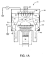
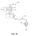
Figures 1 a and 1b provides an illustration of an apparatus suitable for
performing chamber cleaning using an internal energy source or a remote energy
source, respectively.
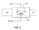
Figure 2 provides an illustration of an apparatus for performing a process of the
invention using plasma as the energy source.
Figure 3 provides a graphical illustration of the relative BCl3 plasma etch rates
of various high dielectric constant materials, normalized to Al2O3.
Figure 4 provides an illustration of an apparatus for performing a process of the
invention using thermal heating as the energy source
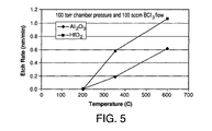
Figure 5 provides an illustration of the etch rate-dependence on lower
electrode/pedestal set temperature at constant chamber pressure and BCl3 flow rate.
Figure 6 provides an illustration of the etch rate dependence on chamber
pressure at constant lower electrode set temperature and BCl3 flow rate.
DETAILED DESCRIPTION OF THE INVENTION
The inventive process is useful for dry-etching high-k materials and dry-cleaning
chemical vapor deposition (CVD) chambers (and more specifically, ALD chambers) used
to deposit high-k materials onto wafer surfaces. The material to be removed from the
surface being etched or cleaned is converted from a solid non-volatile material into
species that have higher volatility than the high-k materials deposited thereupon and can
be subsequently removed, for example, by reactor vacuum pumps. Thus, in preferred
embodiments, the invention removes a substance from a substrate using a reactive
agent to volatilize the substance. Unlike wet-etching and wet-cleaning processes, dry-etching
and dry-cleaning processes do not immerse the substrate in or expose the
substrate to liquid chemical solutions.
In certain embodiments, the substance to be removed can be a transition metal
oxide, a transition metal silicate, a Group 13 metal oxide or a Group 13 metal silicate (in
accordance with the IUPAC Nomenclature of Inorganic Chemistry, Recommendations
1990, Group 13 metals include Al, Ga, In and Tl, and the transition metals occupy
Groups 3-12). The substance may be a high-k material having a dielectric constant
greater than that of silicon dioxide (i.e., greater than about 4.1), more preferably greater
than 5, even more preferably at least 7. Preferably, the substance is at least one
member selected from the group consisting of Al2O3, HfO2, ZrO2, HfSixOy, ZrSixOy, and
mixtures thereof. Those skilled in the art will appreciate that the formula HfSixOy (and the
formula ZrSixOy) represents a mixture of HfO2 (ZrO2) and SiO2, where x is greater than 0
and y is 2x + 2.
In other embodiments of the present invention, the substance may be a
laminate comprising layers of at least one member selected from the group of the
following materials: a transition metal oxide, a transition metal silicate, a Group 13 metal
oxide, a Group 13 metal silicate, a nitrogen containing transition metal oxide, a nitrogen
containing transition metal silicate, a nitrogen containing Group 13 metal oxide, or a
nitrogen containing Group 13 metal silicate. The laminate is preferably alternating
between at least one of the foregoing materials and, optionally, other materials such as
insulating materials. For example, the laminate may be comprised of alternating layers
of HfO2 and Al2O3. The laminate may also consist of a certain number of layers of a first
material and a certain number of layers of a second material or, alternatively, outer
layers of at least one first material and inner layers of at least one second material.
In yet a further embodiment of the present invention, the substance may be a
nitrogen containing material such as a nitrogen containing transition metal oxide, a
nitrogen containing transition metal silicate, a nitrogen containing Group 13 metal oxide,
or a nitrogen containing Group 13 metal silicate. An example of this type of substance
includes HfAION.
As mentioned previously, the substance to be removed is reacted with a
reactive agent to form a volatile product which can be readily removed from the
substrate. In certain preferred embodiments, the reactive agent may be exposed to one
or more energy sources sufficient to form active species which react and form the volatile
product. Examples of suitable reactive agents include: a halogen-containing compound
such as a chloride, bromide, or iodide compound; a boron-containing compound, a
carbon-containing compound, a hydrogen-containing compound, a nitrogen-containing
compound , a chelating compound, a chlorosilane compound, a hydrochlorosilane
compound, an organochlorosilane compound, or a mixture thereof. Although the
reactive agents used herein may be sometimes described as "gaseous", it is understood
that the chemical reagents may be delivered directly as a gas to the reactor, delivered as
a vaporized liquid, a sublimed solid and/or transported by an inert diluent gas into the
reactor.
The reactive agents can be delivered to the reaction chamber by a variety of
means, such as, for example, conventional cylinders, safe delivery systems, vacuum
delivery systems, solid or liquid-based generators that create the reactive agent at the
point of use. In one embodiment of the present invention, at least one reactive agent
can be added to a non-reactive liquid or gaseous diluent and applied to the substrate
having the substance to be removed as a spray or other means. The reactive agent can
react with the substance to form the volatile product upon exposure to one or more
energy sources. In an alternative embodiment such as for chamber cleaning
applications, the reactive agent(s) can be deposited onto a non-reactive support which
can be introduced into the reaction chamber. The material of the non-reactive support is
one that will not react with the reactive agent prior to or during exposure to one of energy
sources. In certain preferred embodiments, the non-reactive support has a plurality of
pores. The reactive agent(s) can be released upon exposure to one or more energy
sources and react with the substance to be removed to form the volatile product.
Since the chlorides of these metals (such as AlCl3, HfCl4, ZrCl4, and SiCl4) are
more volatile, it is preferred to convert these high-k substances into chlorides. This
conversion is accomplished by contacting the substance to be removed with a reactive
agent containing chlorine. Preferred examples of chlorine-containing reactive agents
include BCl3, COCl2, HCI, Cl2, ClF3, and NFxCl3-x, where x is an integer from 0 to 2,
chlorocarbons, and chlorohydrocarbons (such as CxHyClz where x is a number ranging
from 1 to 6, y is a number ranging from 0 to 13, and z is a number ranging from 1 to 14).
Chlorine-containing reactive agents that also contain oxygen-getter functions, such as
BCl3, COCl2, chlorocarbons and chlorohydrocarbons, are more preferred because the
oxygen-getter component (B, CO, C, or H) in these molecules extracts oxygen from the
high-k materials and hence enhances the conversion of metal oxides and metal silicates
into metal chlorides. Among the chlorine-containing and oxygen-getter gases, BCl3 is
the most preferred one. In embodiments employing COCl2 as the reactive agent it can
be provided in prepared form or formed by an in situ reaction of CO and Cl2. In
embodiments for removing metal silicates, the reactive agent can comprise a chlorine-containing
gas and a fluorine-containing gas (e.g., BCl3 and BF3), or a gas containing
both fluorine and chlorine such as ClF3, and NFzCl3-z, where z is an integer from 0 to 2.
In addition to the reactive agents described herein, inert diluent gases such as
nitrogen, CO2, helium, neon, argon, krypton, and xenon etc. can also be added. Inert
diluent gases can modify the plasma characteristics and cleaning processes to better
suit some specific applications. The concentration of the inert gases can range from 0 to
99%.
The process of the invention is useful for etching substances from the surfaces
of a substrate. Thus, suitable substrates for the etching embodiments of the invention
include, e.g., semiconductor wafers and the like. Figure 3 shows a comparison of the
relative etch rate of hafnium oxide, aluminum oxide, and zirconium oxide for one
embodiment of the present invention using BCl3 as the reactive agent.
. The present invention may be also suitable for cleaning substances from
substrates such as surfaces of reaction chambers for CVD and/or ALD processes. The
present invention is particularly suited for removing high k substances that have
deposited onto the exposed surfaces of a reaction chamber such as, for example, the
workpiece platform, grounded sidewalls, and/or showerhead of a typical reaction
chamber.
Thermal or plasma activation and/or enhancement can significantly impact the
efficacy of dry etching and dry cleaning of high-k materials. For thermal activation, the
substrate can be heated up to 600 °C, more preferably up to 400°C, and even more
preferably up to 300 °C. The pressure range is generally 10 mTorr to 760 Torr, more
preferably 1 Torr to 760 Torr.
For in situ plasma activation, one can generate the plasma with a 13.56 MHz
RF power supply, with RF power density at least 0.2 W/cm2, more preferably at least 0.5
W/cm2, even more preferably at least 1 W/cm2. One can also operate the in situ plasma
at RF frequencies lower than 13.56 MHz to enhance ion assisted cleaning of grounded
ALD chamber walls. The operating pressure is generally in the range of 2.5 mTorr to
100 Torr, more preferably 5 mTorr to 50 Torr, even more preferably 10 mTorr to 20 Torr.
Optionally, one can also combine thermal and plasma enhancement for more effective
cleaning of ALD chamber walls.
One can also use a remote plasma source to replace an in situ plasma to
generate more reactive species. The remote plasma source can be generated by either
an RF or a microwave source. In addition, reactions between remote plasma generated
reactive species and high-k materials can be activated/enhanced by heating ALD reactor
components to elevated temperatures up to 600 °C, more preferably up to 400 °C, and
even more preferably up to 300 °C.
Other means of activation and enhancement to the cleaning processes can also
be employed. For example, one can use photon induced chemical reactions to generate
reactive species and enhance the etching/cleaning reactions.
The following tables show thermochemical calculations for preferred reactions
for volatilizing the substance to be removed from the substrate. In these tables, K
eq
represents the equilibrium constant for the reaction as written; so that the larger this
value is, the more favorable the reaction will be to proceed.
| Al2O3 reaction with BCl3: Al2O3 + 2BCl3(g) ↔ B2O3 + 2AlCl3(g) |
| Temperature (°C) | ΔH (Kcal) | ΔS (Cal) | ΔG (Kcal) | Keq |
| 0.000 | 9.561 | 12.274 | 6.208 | 1.078E-005 |
| 100.000 | 9.547 | 12.249 | 4.976 | 1.217E-003 |
| 200.000 | 9.424 | 11.959 | 3.766 | 1.822E-002 |
| 300.000 | 9.299 | 11.719 | 2.582 | 1.036E-001 |
| 400.000 | 9.196 | 11.553 | 1.419 | 3.461E-001 |
| 500.000 | 15.123 | 19.739 | -0.138 | 1.094E+000 |
| 600.000 | 15.476 | 20.169 | -2.135 | 3.422E+000 |
| 700.000 | 15.748 | 20.464 | -4.167 | 8.629E+000 |
| 800.000 | 15.951 | 20.664 | -6.224 | 1.852E+001 |
| 900.000 | 16.097 | 20.794 | -8.298 | 3.515E+001 |
| 1000.000 | 16.190 | 20.871 | -10.381 | 6.056E+001 |
| HfO2 reaction with BCl3: 1.5HfO2 + 2BCl3(g) ↔ 1.5HfCl4(g) + B2O3 |
| Temperature (°C) | ΔH (Kcal) | ΔS (Cal) | ΔG (Kcal) | Keq |
| 0.000 | -17.999 | -12.638 | -14.547 | 4.367E+011 |
| 25.000 | -18.003 | -12.653 | -14.231 | 2.707E+010 |
| 50.000 | -18.025 | -12.721 | -13.914 | 2.576E+009 |
| 75.000 | -18.057 | -12.817 | -13.595 | 3.426E+008 |
| 100.000 | -18.096 | -12.924 | -13.273 | 5.950E+007 |
| 125.000 | -18.138 | -13.034 | -12.948 | 1.283E+007 |
| 150.000 | -18.182 | -13.141 | -12.621 | 3.305E+006 |
| 175.000 | -18.226 | -13.242 | -12.291 | 9.879E+005 |
| 200.000 | -18.268 | -13.335 | -11.959 | 3.346E+005 |
| ZrO2 reaction with BCl3: 1 .5ZrO2 + 2BCl3(g) ↔ 1.5ZrCl4(g) + B2O3 |
| Temperature (°C) | ΔH (Kcal) | ΔS (Cal) | ΔG (Kcal) | Keq |
| 0.000 | -29.845 | -12.107 | -26.538 | 1.717E+021 |
| 25.000 | -29.825 | -12.038 | -26.236 | 1.710E+019 |
| 50.000 | -29.822 | -12.026 | -25.935 | 3.481 E+017 |
| 75.000 | -29.828 | -12.047 | -25.634 | 1.239E+016 |
| 100.000 | -29.842 | -12.083 | -25.333 | 6.891E+014 |
| 125.000 | -29.858 | -12.126 | -25.030 | 5.502E+013 |
| 150.000 | -29.875 | -12.168 | -24.726 | 5.913E+012 |
| 175.000 | -29.892 | -12.207 | -24.422 | 8.142E+011 |
| 200.000 | -29.908 | -12.240 | -24.116 | 1.381E+011 |
| HfO2 reaction with COCl2: HfO2+ 2COCl2(g)↔HfCl4(g)+2CO2(g) |
| Temperature (°C) | ΔH (Kcal) | ΔS (Cal) | ΔG (Kcal) | Keq |
| 0.000 | -20.643 | 41.960 | -32.105 | 4.890E+025 |
| 25.000 | -20.649 | 41.940 | -33.153 | 2.014E+024 |
| 50.000 | -20.668 | 41.878 | -34.201 | 1.357E+023 |
| 75.000 | -20.699 | 41.787 | -35.247 | 1.343E+022 |
| 100.000 | -20.739 | 41.677 | -36.290 | 1.806E+021 |
| 125.000 | -20.786 | 41.554 | -37.331 | 3.112E+020 |
| 150.000 | -20.840 | 41.423 | -38.368 | 6.578E+019 |
| 175.000 | -20.900 | 41.285 | -39.402 | 1.647E+019 |
| 200.000 | -20.965 | 41.144 | -40.432 | 4.757E+018 |
| ZrO2 reaction with COCl2: ZrO2 + 2COCl2(g) ↔ ZrCl4g) + 2CO2(g) |
| Temperature (°C) | ΔH (Kcal) | ΔS (Cal) | ΔG (Kcal) | Keq |
| 0.000 | -28.540 | 42.313 | -40.098 | 1.218E+032 |
| 25.000 | -28.530 | 42.350 | -41.157 | 1.483E+030 |
| 50.000 | -28.533 | 42.341 | -42.215 | 3.573E+028 |
| 75.000 | -28.547 | 42.300 | -43.273 | 1.469E+027 |
| 100.000 | -28.569 | 42.238 | -44.330 | 9.244E+025 |
| 125.000 | -28.599 | 42.160 | -45.385 | 8.215E+024 |
| 150.000 | -28.636 | 42.071 | -46.438 | 9.694E+023 |
| 175.000 | -28.678 | 41.975 | -47.489 | 1.448E+023 |
| 200.000 | -28.724 | 41.873 | -48.537 | 2.638E+022 |
| ZrSiO4 reaction-with BCl3: ZrSiO4 + 2.667BCl3(g) ↔ SiCl4(g) + ZrCl4(g) + 1.333B2O3 |
| Temperature (°C) | ΔH (Kcal) | ΔS (Cal) | ΔG (Kcal) | Keq |
| 0.000 | -31.065 | -21.096 | -25.303 | 1.764E+020 |
| 25.000 | -31.003 | -20.879 | -24.778 | 1.460E+018 |
| 50.000 | -30.962 | -20.747 | -24.258 | 2.554E+016 |
| 75.000 | -30.935 | -20.665 | -23.740 | 8.020E+014 |
| 100.000 | -30.916 | -20.613 | -23.224 | 4.013E+013 |
| 125.000 | -30.902 | -20.577 | -22.710 | 2.928E+012 |
| 150.000 | -30.891 | -20.549 | -22.196 | 2.914E+011 |
| 175.000 | -30.879 | -20.523 | -21.682 | 3.755E+010 |
| 200.000 | -30.867 | -20.496 | -21.169 | 6.012E+009 |
| 225.000 | -30.852 | -20.466 | -20.657 | 1.158E+009 |
| 250.000 | -30.835 | -20.432 | -20.146 | 2.612E+008 |
| 275.000 | -30.814 | -20.393 | -19.636 | 6.754E+007 |
| 300.000 | -30.790 | -20.349 | -19.127 | 1.967E+007 |
| 325.000 | -30.761 | -20.300 | -18.618 | 6.358E+006 |
| 350.000 | -30.729 | -20.247 | -18.112 | 2.252E+006 |
| 375.000 | -30.692 | -20.190 | -17.606 | 8.652E+005 |
| 400.000 | -30.652 | -20.130 | -17.102 | 3.572E+005 |
| 425.000 | -30.608 | -20.066 | -16.600 | 1.573E+005 |
| 450.000 | -22.891 | -9.391 | -16.100 | 7.349E+004 |
| 475.000 | -22.663 | -9.081 | -15.869 | 4.327E+004 |
| 500.000 | -22.443 | -8.791 | -15.646 | 2.649E+004 |
| ZrSiO4 reaction with BF3 and BGl3: ZrSiO4 + 1.333BF3(g) + 1.333BCl3(g)↔ SiF4(g) + ZrCl4(g) + 1.333B2O3 |
| Temperature (°C) | ΔH (Kcal) | ΔS (Cal) | ΔG (Kcal) | Keq |
| 0.000 | -25.010 | -21.014 | -19.270 | 2.627E+015 |
| 25.000 | -24.951 | -20.807 | -18.748 | 5.540E+013 |
| 50.000 | -24.912 | -20.681 | -18.229 | 2.136E+012 |
| 75.000 | -24.885 | -20.600 | -17.713 | 1.319E+011 |
| 100.000 | -24.865 | -20.545 | -17.199 | 1.186E+010 |
| 125.000 | -24.849 | -20.502 | -16.686 | 1.445E+009 |
| 150.000 | -24.833 | -20.463 | -16.174 | 2.260E+008 |
| 175.000 | -24.816 | -20.423 | -15.663 | 4.354E+007 |
| 200.000 | -24.796 | -20.380 | -15.153 | 9.992E+006 |
| 225.000 | -24.772 | -20.332 | -14.644 | 2.661E+006 |
| 250.000 | -24.745 | -20.278 | -14.136 | 8.053E+005 |
| 275.000 | -24.712 | -20.218 | -13.630 | 2.721E+005 |
| 300.000 | -24.675 | -20.152 | -13.125 | 1.012E+005 |
| 325.000 | -24.633 | -20.080 | -12.622 | 4.095E+004 |
| 350.000 | -24.586 | -20.003 | -12.121 | 1.784E+004 |
| 375.000 | -24.535 | -19.922 | -11.622 | 8.303E+003 |
| 400.000 | -24.478 | -19.837 | -11.125 | 4.095E+003 |
| 425.000 | -24.418 | -19.749 | -10.630 | 2.128E+003 |
| 450.000 | -16.684 | -9.050 | -10.139 | 1.160E+003 |
| 475.000 | -16.439 | -8.717 | -9.917 | 7.894E+002 |
| 500.000 | -16.201 | -8.405 | -9.703 | 5.535E+002 |
Tables 1-7 show that BCl3 and COCl2 can be used as the etchants for dry
etching and cleaning of the high-k materials. BCl3 (boron trichloride) is a liquefied gas at
room temperature and can be readily delivered into ALD reactors for chamber cleaning.
COCl2 (phosgene) is preferably provided in situ in etch or deposition reactors by reacting
gaseous carbon monoxide and chlorine to form phosgene assisted by an external energy
source (e.g. plasma) as follows:
CO (g) + Cl2 (g) → COCl2
In other embodiments of the present invention such as applications that are
sensitive to boron residue, chlorocarbons (CC) and hydrochlorocarbons (HCC) may be
employed as the reactive agent because these compounds may contain chlorine as well
as oxygen getter components (C or H). The general formula for the CC and HCC
compounds is CxHyClz, where x ranges from 1 to 6, y ranges from 0 to 13, and z ranges
from 1 to 14. Examples of suitable CC and HCC compounds include, but are not limited
to, trans-dichloroethylene C2H2Cl2 (a.k.a. Trans-LC® ), cis-dichloroethylene, 1,1-dichloroethylele,
1,1,1-trichloroethane (C2H3Cl3), or tetrachloroethylene C2Cl4, C4H4Cl4 ,
CHCl3, and CCl4 Some CC and HCC compounds may react with high-k metal oxides
without the addition of oxygen. For example, in some embodiments, tetrachloroethylene
(C2Cl4) can react with Al2O3 to form volatile byproducts as follows:
1.5C2Cl4(g) + Al2O3 → 2AlCl3(g) + 3CO(g)
Table 8 illustrates that the reaction is thermodynamically favorable at temperatures
above 100 °C.
| Thermodynamic data for reaction: 1.5C2Cl4(g) + Al2O3 = 2AlCl3(g) + 3CO(g) |
| T (°C) | ΔH (kcal) | ΔS (cal) | ΔG (kcal) | Keq |
| 0.000 | 46.723 | 157.382 | 3.734 | 1.028E-003 |
| 100.000 | 46.760 | 157.552 | -12.031 | 1.114E+007 |
| 200.000 | 46.314 | 156.508 | -27.738 | 6.509E+012 |
| 300.000 | 45.599 | 155.144 | -43.322 | 3.317E+016 |
| 400.000 | 44.704 | 153.709 | -58.765 | 1.204E+019 |
| 500.000 | 43.674 | 152.284 | -74.064 | 8.667E+020 |
| 600.000 | 42.541 | 150.907 | -89.223 | 2.160E+022 |
| 700.000 | 41.340 | 149.605 | -104.248 | 2.594E+023 |
| 800.000 | 40.087 | 148.380 | -119.147 | 1.848E+024 |
| 900.000 | 38.793 | 147.228 | -133.927 | 8.948E+024 |
| 1000.000 | 37.467 | 146.143 | -148.595 | 3.236E+025 |
The above thermochemical calculations are illustrations of limiting cases for
those chemical reactions. In addition to the limiting case reaction products such as B2O3,
intermediate reaction products such as boron oxychloride (BOCI) can also be formed in
reactions between high-k materials and BCl3. Intermediate reaction products such as
BOCI have higher volatility and thus may further enhance the removal of high-k
materials.
Other CC and HCC compounds may need the addition of oxygen to release
chlorine without forming carbon residues (soot). For example, trans-dichloroethylene
(C2H2Cl2) (a.k.a. Trans-LC® ) can react with Al2O3 at an O2:C2H2Cl2 molar ratio of 2:1,
6O2(g) + Al2O3 + 3C2H2Cl2(g) = 2AlCl3(g) + 6CO2(g) + 3H2O(g)
Table 9 shows such a reaction is thermodynamically favorable at temperatures between
0 and 1000 °C.
| Thermodynamic data for reaction: 6O2(g) + Al2O3 + 3C2H2Cl2(g) = 2AlCl3(g) + 6CO2(g) + 3H2O(g) |
| T (°C) | ΔH (kcal) | ΔS (kcal) | ΔG (kcal) | Keq |
| 0.000 | -616.464 | 77.981 | -637.764 | 1.000E+308 |
| 100.000 | -616.428 | 78.113 | -645.576 | 1.000E+308 |
| 200.000 | -616.656 | 77.585 | -653.365 | 6.559E+301 |
| 300.000 | -617.145 | 76.654 | -661.079 | 1.257E+252 |
| 400.000 | -617.872 | 75.490 | -668.688 | 1.316E+217 |
| 500.000 | -618.811 | 74.193 | -676.173 | 1.422E+191 |
| 600.000 | -619.918 | 72.848 | -683.525 | 1.261E+171 |
| 700.000 | -621.140 | 71.523 | -690.743 | 1.380E+155 |
| 800.000 | -622.440 | 70.253 | -697.832 | 1.340E+142 |
| 900.000 | -623.784 | 69.056 | -704.796 | 2.040E+131 |
| 1000.000 | -625.138 | 67.947 | -711.646 | 1.485E+122 |
An excess amount of oxygen is undesirable in the above reactions since excess
O2 can convert metal chlorides back to metal oxides. A better way to prevent excess
oxygen is to oxidize carbon only partially into CO by running the reaction under an
oxygen lean condition. For example, O2:C2H2Cl2 molar ratio of 1:1 can lead to the
formation of CO and AlCl3 as the byproducts:
3C2H2Cl2(g) + Al2O3 + 3O2 = 2AlCl3(g) + 6CO(g) + 3H2O(g)
As shown in Table 10, such partial oxidation reaction is also favorable
thermodynamically.
| Thermodynamic data for reaction: 3C2H2Cl2(g) + Al2O3 + 3O2 = 2AlCl3(g) + 6CO(g) + 3H2O(g) |
| T (°C) | ΔH (kcal) | ΔS (kcal) | ΔG (kcal) | Keq |
| 0.000 | -210.973 | 200.961 | -265.865 | 5.480E+212 |
| 100.000 | -210.103 | 203.760 | -286.136 | 3.984E+167 |
| 200.000 | -210.055 | 203.905 | -306.532 | 3.982E+141 |
| 300.000 | -210.561 | 202.949 | -326.881 | 4.512E+124 |
| 400.000 | -211.485 | 201.470 | -347.105 | 5.046E+112 |
| 500.000 | -212.749 | 199.725 | -367.166 | 6.267E+103 |
| 600.000 | -214.276 | 197.870 | -387.046 | 7.688E+096 |
| 700.000 | -215.992 | 196.011 | -406.740 | 2.255E+091 |
| 800.000 | -217.847 | 194.197 | -426.250 | 6.518E+086 |
| 900.000 | -219.797 | 192.461 | -445.582 | 1.037E+083 |
| 1000.000 | -221.800 | 190.822 | -464.745 | 6.097E+079 |
Instead of oxygen, chlorine (Cl2) can be added to prevent the formation of
carbon soot. For example, Cl2:C2H2Cl2 molar ratio of 2:1 allows the following reaction:
2Cl2(g) + Al2O3 + C2H2Cl2(g) = 2AlCl3(g)+ H2O(g)
Similarly, Cl2:C2H2Cl2 molar ratio of 4:1 allows the following reaction:
4Cl2(g) + Al2O3 + C2H2Cl2(g) = 3.333AlCl3(g) + H2O(g) + 2CO2(g)
Both reactions are thermodynamically favorable, as shown in Tables 11 and 12. The
use of chlorine to control soot formation is more desirable since excess amount of
chlorine helps the chlorination of metal oxides.
| Thermodynamic data for reaction: 2Cl2(g) + Al2O3 + C2H2Cl2(g) = 2AlCl3(g) + H2O(g) +2CO(g) |
| T (°C) | ΔH (kcal) | ΔS (kcal) | ΔG (kcal) | Keq |
| 0.000 | 10.291 | 101.403 | -17.407 | 8.479E+013 |
| 100.000 | 10.619 | 102.465 | -27.616 | 1.498E+016 |
| 200.000 | 10.554 | 102.326 | -37.861 | 3.088E+017 |
| 300.000 | 10.225 | 101.701 | -48.065 | 2.135E+018 |
| 400.000 | 9.697 | 100.855 | -58.194 | 7.859E+018 |
| 500.000 | 9.005 | 99.900 | -68.233 | 1.946E+019 |
| 600.000 | 8.185 | 98.904 | -78.173 | 3.701E+019 |
| 700.000 | 7.277 | 97.920 | -88.014 | 5.858E+019 |
| 800.000 | 6.303 | 96.967 | -97.758 | 8.134E+019 |
| 900.000 | 5.280 | 96.056 | -107.409 | 1.026E+020 |
| 1000.000 | 4.224 | 95.193 | -116.971 | 1.205E+020 |
| Thermodynamic data for reaction: 4Cl2(g) + Al2O3 + C2H2Cl2(g) = 3.333AlCl3(g) + H2O(g) + 2CO2(g) |
| T (°C) | ΔH (kcal) | ΔS (kcal) | ΔG (kcal) | Keq |
| 0.000 | -44.076 | 94.797 | -69.970 | 9.734E+055 |
| 100.000 | -43.990 | 95.096 | -79.475 | 3.562E+046 |
| 200.000 | -44.229 | 94.542 | -88.962 | 1.245E+041 |
| 300.000 | -44.715 | 93.617 | -98.372 | 3.262E+037 |
| 400.000 | -45.399 | 92.520 | -107.680 | 9.182E+034 |
| 500.000 | -46.255 | 91.338 | -116.873 | 1.096E+033 |
| 600.000 | -47.248 | 90.132 | -125.946 | 3.365E+031 |
| 700.000 | -48.328 | 88.961 | -134.900 | 1.988E+030 |
| 800.000 | -49.475 | 87.840 | -143.740 | 1 .886E+029 |
| 900.000 | -50.671 | 86.775 | -152.470 | 2.550E+028 |
| 1000.000 | -51.901 | 85.769 | -161.097 | 4.532E+027 |
In addition to the chloride compounds, the bromide and iodide compounds of
these high-k materials, such as AlBr
3, All
3, HfBr
4, Hfl
4, ZrBr
4, and Zrl
4 have a volatility
similar to their corresponding chlorides. Therefore, some bromo- and iodo-compounds
can also be used to etch/clean these high-k materials. Bromine and iodine ions are
heavier than chlorine ions, hence bromine and iodine ions can provide more effective
sputtering to energize plasma-assisted etch/clean reactions with high-k materials.
Bromine and iodine atoms have higher surface sticking coefficients than chlorine atoms.
A higher sticking coefficient relates to a higher probability for bromine and iodine
atoms/ions to be adsorbed onto the surface of high-k materials hence enhancing the
bromination/iodization reactions. Desirable bromo- and iodo-compounds preferably
contain an oxygen-getter function in the molecule. Examples of suitable bromine and
iodine containing compounds include boron tribromide (BBr
3), boron triiodide (Bl
3),
hydrogen bromide (HBr), hydro iodide (HI), bromocarbons such as CBr
4,
bromohydrocarbons such as trans-dibromoethylene (C
2H
2Br
2), iodocarbons such as Cl
4,
and iodohydrocarbons such as trans-diiodoethylene (C
2H
2l
2) etc. For HfO
2, the bromine
and iodine chemistries are dramatically more favorable than the corresponding chlorine
chemistry, as shown in tables 13-15.
| Thermodynamic data for reaction: 1.5HfO2 + 2BCl3(g) = 1.5HfCl4(g) + B2O3 |
| T (°C) | ΔH (kcal) | ΔS (kcal) | ΔG (kcal) | Keq |
| 0.000 | -17.999 | -12.638 | -14.547 | 4.367E+011 |
| 100.000 | -18.096 | -12.924 | -13.273 | 5.950E+007 |
| 200.000 | -18.268 | -13.335 | -11.959 | 3.346E+005 |
| 300.000 | -18.413 | -13.614 | -10.611 | 1.113E+004 |
| 400.000 | -18.507 | -13.765 | -9.241 | 1.001 E+003 |
| 500.000 | -12.540 | -5.525 | -8.268 | 2.175E+002 |
| 600.000 | -12.126 | -5.020 | -7.743 | 8.672E+001 |
| 700.000 | -11.790 | -4.655 | -7.260 | 4.271 E+001 |
| 800.000 | -11.524 | -4.395 | -6.808 | 2.436E+001 |
| 900.000 | -11.321 | -4.213 | -6.378 | 1.543E+001 |
| 1000.000 | -11.176 | -4.094 | -5.963 | 1.056E+001 |
| Thermodynamic data for reaction: 1.5HfO2 + 2BBr3(g) = 1.5HfBr4(g) + B2O3 |
| T (°C) | ΔH (kcal) | ΔS (kcal) | ΔG (kcal) | Keq |
| 0.000 | -53.997 | -10.093 | -51.241 | 1.003E+041 |
| 100.000 | -54.122 | -10.459 | -50.219 | 2.602E+029 |
| 200.000 | -54.371 | -11.049 | -49.143 | 5.026E+022 |
| 300.000 | -54.601 | -11.492 | -48.014 | 2.042E+018 |
| 400.000 | -54.773 | -11.770 | -46.850 | 1.629E+015 |
| 500.000 | -48.872 | -3.621 | -46.073 | 1.058E+013 |
| 600.000 | -48.508 | -3.178 | -45.734 | 2.806E+011 |
| 700.000 | -48.207 | -2.851 | -45.433 | 1.600E+010 |
| 800.000 | -47.960 | -2.609 | -45.161 | 1.577E+009 |
| 900.000 | -47.761 | -2.431 | -44.909 | 2.328E+008 |
| 1000.000 | -47.606 | -2.304 | -44.673 | 4.669E+007 |
| Thermodynamic data for reaction: 1.5HfO2 + 2Bl3(g) = 1.5Hfl4(g) + B2O3 |
| T (°C) | ΔH (kcal) | ΔS (kcal) | ΔG (kcal) | Keq |
| 0.000 | -58.042 | -15.921 | -53.694 | 9.212E+042 |
| 100.000 | -58.342 | -16.842 | -52.057 | 3.104E+030 |
| 200.000 | -58.692 | -17.675 | -50.329 | 1.775E+023 |
| 300.000 | -58.991 | -18.250 | -48.531 | 3.214E+018 |
| 400.000 | -59.216 | -18.614 | -46.686 | 1.442E+015 |
| 500.000 | -53.362 | -10.530 | -45.221 | 6.080E+012 |
| 600.000 | -53.042 | -10.139 | -44.189 | 1 .152E+011 |
| 700.000 | -52.784 | -9.859 | -43.190 | 5.015E+009 |
| 800.000 | -52.581 | -9.660 | -42.214 | 3.961 E+008 |
| 900.000 | -52.429 | -9.524 | -41.256 | 4.856E+007 |
| 1000.000 | -52.324 | -9.438 | -40.308 | 8.315E+006 |
Similarly, bromine and iodine chemistries are also thermodynamically favorable
for reactions with Al
2O
3 and ZrO
2, as shown in Tables 16-18.
| Thermodynamical data for reaction: 2BBr3(g) + Al2O3 = 2AlBr3(g) + B2O3 |
| T (°C) | ΔH (kcal) | ΔS (kcal) | ΔG (kcal) | Keq |
| 0.000 | -2.212 | 12.687 | -5.678 | 3.493E+004 |
| 100.000 | -2.279 | 12.503 | -6.944 | 1.168E+004 |
| 200.000 | -2.482 | 12.022 | -8.170 | 5.945E+003 |
| 300.000 | -2.685 | 11.632 | -9.352 | 3.683E+003 |
| 400.000 | -2.852 | 11.362 | -10.501 | 2.567E+003 |
| 500.000 | 3.023 | 19.476 | -12.035 | 2.525E+003 |
| 600.000 | 3.337 | 19.858 | -14.003 | 3.200E+003 |
| 700.000 | 3.579 | 20.122 | -16.003 | 3.928E+003 |
| 800.000 | 3.764 | 20.303 | -18.024 | 4.688E+003 |
| 900.000 | 3.897 | 20.422 | -20.061 | 5.464E+003 |
| 1000.000 | 3.985 | 20.494 | -22.107 | 6.241E+003 |
| Thermodynamical data for reaction: 2BBr3(g) + 1.5ZrO2 = 1.5ZrBr4(g) + B2O3 |
| T (°C) | ΔH (kcal) | ΔS (kcal) | ΔG (kcal) | Keq |
| 0.000 | -44.096 | -11.573 | -40.935 | 5.691 E+032 |
| 100.000 | -44.194 | -11.861 | -39.768 | 1.965E+023 |
| 200.000 | -44.363 | -12.264 | -38.560 | 6.495E+017 |
| 300.000 | -44.489 | -12.509 | -37.320 | 1.706E+014 |
| 400.000 | -44.545 | -12.600 | -36.064 | 5.125E+011 |
| 500.000 | -38.522 | -4.282 | -35.212 | 9.000E+009 |
| 600.000 | -38.033 | -3.686 | -34.815 | 5.186E+008 |
| 700.000 | -37.604 | -3.220 | -34.470 | 5.520E+007 |
| 800.000 | -37.229 | -2.853 | -34.167 | 9.096E+006 |
| 900.000 | -36.902 | -2.561 | -33.897 | 2.067E+006 |
| 1000.000 | -36.619 | -2.330 | -33.653 | 5.989E+005 |
| Thermodynamical data for reaction: 2Bl3(g) + 1.5ZrO2 = 1.5Zrl4(g) + B2O3 |
| T (°C) | ΔH (kcal) | ΔS (kcal) | ΔG (kcal) | Keq |
| 0.000 | -74.430 | -11.695 | -71.235 | 1.001E+057 |
| 100.000 | -74.587 | -12.171 | -70.045 | 1.067E+041 |
| 200.000 | -74.805 | -12.689 | -68.801 | 6.053E+031 |
| 300.000 | -74.972 | -13.013 | -67.514 | 5.573E+025 |
| 400.000 | -75.065 | -13.163 | -66.204 | 3.134E+021 |
| 500.000 | -69.074 | -4.891 | -65.293 | 2.873E+018 |
| 600.000 | -68.614 | -4.330 | -64.833 | 1.695E+016 |
| 700.000 | -68.212 | -3.894 | -64.423 | 2.947E+014 |
| 800.000 | -67.861 | -3.549 | -64.052 | 1.110E+013 |
| 900.000 | -67.555 | -3.276 | -63.711 | 7.411E+011 |
| 1000.000 | -67.291 | -3.061 | -63.394 | 7.642E+010 |
In certain embodiments, the reactive agent may comprise a chelating
compound. A chelating compound, as used herein, describes a compound that contains
at least two electron-rich (e.g., Lewis base) sites that could potentially interact with an
electron-deficient (e.g., Lewis acid) metal atom such as, but not limited to, Zr, Al, or Hf. It
is not required, however, that the plurality of sites simultaneously interact with the metal
in order. Also, the chelating compound may be delivered into the reaction chamber as a
conjugate acid of the basic site. Examples of these compounds may be found in U. S.
Pat. No. 3,634,477. Further examples of chelating compounds include oxy-halocarbon
compounds, such as chloroacetic acid, oxalyl chloride, etc., are known to be chelating
compounds or agents that can react with metal oxides and metal chlorides to form
volatile byproducts. Some exemplary chelating compounds may have the formula
CαHβXγYδOε, wherein X and Y are one of the halogen atoms F, Cl, Br, and I; α is a
number ranging from 1 to 6, β is a number ranging from 0 to 13, the sum of γ+ δ is a
number ranging from 1 to 14, and ε is a number ranging from 1 to 6. Examples of these
compounds include hexafluoropetanedione (CCl3C(O)CH2C(O)CCl3) (a.k.a. Hhfac),
hexachloropetanedione (CCl3C(O)CH2C(O)CCl3), hexafluoroacetone (CF3C(O)CF3) and
hexachloroacetone (CCl3C(O)CCl3). For example, hexafluoropetanedione (a.k.a. Hhfac)
(CF3C(O)CH2C(O)CF3, or C5H2O2F6) is a common chelating agent that can react with a
wide variety of metal oxides and/or chlorides to form volatile organo-metal compounds
M(hfac)x, where M is a metal ion such as Al3+, Hf4+, and Zr4+ etc. Such chelating property
can be used to enhance the etching and chamber cleaning of high-k materials. In
addition, these molecules can be used as an oxygen scavenger to enhance chlorination
of the high-k materials. For example, one can have:
HfO2 + C5H2O2F6 + 2Cl2 + O2 = HfCl4(g) + H2O(g) + 3COF2(g) + 2CO(g)
In certain embodiments of the present invention, the chlorine analog of Hhfac,
hexachloropetanedione (CCl3C(O)CH2C(O)CCl3) may be more advantageous as the
reactive agent since it can be both an oxygen scavenger and a chlorinating agent.
These reactions can be also be assisted by thermal and/or plasma activation. For
example,
C5H2O2Cl6 + Al2O3 + 0.5O2= 2AlCl3(g) + 5CO(g) + H2O(g)
and
2C5H2O2Cl6 + 3HfO2 + O2 = 3HfCl4(g)+ 10CO(g) + 2H2O(g)
To prevent oxidation of the metal chlorides, chlorine can be used to replace
oxygen:
C5H2O2Cl6 + Al2O3 + Cl2= 2AlCl3(g) + 5CO(g) + 2HCl(g)
Chlorosilanes, hydrochlorosilanes, and organochlorosilanes can also be
effective agents to etch/clean high-k materials. Thanks to the highly stable SiO
2
byproduct, these compounds can be both a very effective oxygen scavenger and a
chlorinating agent. Upon exposure to a thermal or plasma source, these compounds can
be just as effective as BCl
3 to convert high-k materials into volatile chlorides without the
potential problem of boron residue contamination. In certain embodiments, the
chlorosilane, hydrochlorosilane, or organochlorosilane compound has the formula
Si
pCl
qR
sH
t, wherein: 1 ≤ p ≤ 3, 1 ≤ q ≤ {2p + 2 - (s+t)}, s and t can have any values
subject to the constraint that 0 < (s + t) ≤ (2p + 1) and R is an organic radical having 1-8
carbon atoms, including: hydrocarbyl (e.g. methyl, ethyl, phenyl, p-tolyl), halocarbyl (e.g.,
trichloromethyl, trifluoromethyl, pentafluoroethyl), halogenated hydrocarbyl (e.g.,
chloromethyl, 2, 4-difluorophenyl), oxygenated hydrocarbyl (e.g., methoxy, hydroxyethyl,
chlorormethoxy) and nitrogen-substituted hydrocarbyl moieties (e.g., aminomethyl,
dimethylaminonomethyl, pyridyl). Exemplary reactions include:
1.5SiCl4(g) + Al2O3 = 2AlCl3(g) + 1 .5SiO2
SiCl4(g) + HfO2 = HfCl4(g) + SiO2
SiCl4(g) + ZrO2 = ZrCl4(g) + SiO2
O2(g) + 2SiHCl3(g) + Al2O3 = 2AlCl3(g) + H2O(g) + 2SiO2
4O2(g) + 2SiCH3Cl3(g) + Al2O3 = 2AlCl3(g) + 3H2O(g) + 2SiO2 + 2CO2(g)
Thermodynamic calculations show that the above reactions are favorable at room
temperature or moderately elevated temperatures, as shown in Tables 19-23.
| Thermodynamical data for reaction: 1.5SiCl4(g) + Al2O3 = 2AlCl3(g) + 1.5SiO2 |
| T (°C) | ΔH (kcal) | ΔS (kcal) | ΔG (kcal) | Keq |
| 0.000 | 32.037 | 34.471 | 22.621 | 7.927E-019 |
| 100.000 | 31.880 | 33.990 | 19.196 | 5.703E-012 |
| 200.000 | 31.647 | 33.439 | 15.825 | 4.895E-008 |
| 300.000 | 31.400 | 32.967 | 12.506 | 1.702E-005 |
| 400.000 | 31.178 | 32.608 | 9.228 | 1.009E-003 |
| 500.000 | 31.009 | 32.373 | 5.980 | 2.039E-002 |
| 600.000 | 31.097 | 32.475 | 2.742 | 2.059E-001 |
| 700.000 | 30.702 | 32.047 | -0.484 | 1.285E+000 |
| 800.000 | 30.291 | 31.645 | -3.669 | 5.587E+000 |
| 900.000 | 30.612 | 31.957 | -6.878 | 1.912E+001 |
| 1000.000 | 30.204 | 31.623 | -10.057 | 5.327E+001 |
| Thermodynamical data for reaction: SiCl4(g) + HfO2 = HfCl4(g) + SiO2 |
| T (°C) | ΔH (kcal) | ΔS (kcal) | ΔG (kcal) | Keq |
| 0.000 | 2.985 | 6.373 | 1.244 | 1.010E-001 |
| 100.000 | 2.825 | 5.878 | 0.631 | 4.267E-001 |
| 200.000 | 2.636 | 5.430 | 0.067 | 9.314E-001 |
| 300.000 | 2.459 | 5.089 | -0.458 | 1.495E+000 |
| 400.000 | 2.317 | 4.860 | -0.955 | 2.042E+000 |
| 500.000 | 2.230 | 4.739 | -1.434 | 2.543E+000 |
| 600.000 | 2.330 | 4.857 | -1.911 | 3.009E+000 |
| 700.000 | 2.110 | 4.618 | -2.385 | 3.432E+000 |
| 800.000 | 1.877 | 4.391 | -2.835 | 3.779E+000 |
| 900.000 | 2.130 | 4.633 | -3.306 | 4.129E+000 |
| 1000.000 | 1.892 | 4.439 | -3.759 | 4.419E+000 |
| Thermodynamical data for reaction: SiCl4(g) + ZrO2 = ZrCl4(g) + SiO2 |
| T (°C) | ΔH (kcal) | ΔS (kcal) | ΔG (kcal) | Keq |
| 0.000 | -4.912 | 6.726 | -6.749 | 2.516E+005 |
| 100.000 | -5.006 | 6.439 | -7.408 | 2.185E+004 |
| 200.000 | -5.123 | 6.160 | -8.038 | 5.164E+003 |
| 300.000 | -5.226 | 5.963 | -8.643 | 1.977E+003 |
| 400.000 | -5.288 | 5.861 | -9.233 | 9.955E+002 |
| 500.000 | -5.292 | 5.854 | -9.818 | 5.966E+002 |
| 600.000 | -5.106 | 6.077 | -10.412 | 4.041E+002 |
| 700.000 | -5.237 | 5.936 | -11.013 | 2.975E+002 |
| 800.000 | -5.375 | 5.800 | -11.600 | 2.304E+002 |
| 900.000 | -5.026 | 6.129 | -12.216 | 1.887E+002 |
| 1000.000 | -5.163 | 6.016 | -12.823 | 1.590E+002 |
| Thermodynamical data for reaction: O2(g) + 2SiHCl3(g) + Al2O3 = 2AlCl3(g) + H2O(g) + 2SiO2 |
| T (°C) | ΔH (kcal) | ΔS (kcal) | ΔG (kcal) | Keq |
| 0.000 | -134.894 | 4.620 | -136.156 | 8.893E+108 |
| 100.000 | -135.412 | 2.993 | -136.529 | 9.339E+079 |
| 200.000 | -135.834 | 1.989 | -136.775 | 1.521E+063 |
| 300.000 | -136.187 | 1.309 | -136.938 | 1.662E+052 |
| 400.000 | -136.464 | 0.863 | -137.045 | 3.145E+044 |
| 500.000 | -136.643 | 0.612 | -137.117 | 5.789E+038 |
| 600.000 | -136.462 | 0.826 | -137.183 | 2.187E+034 |
| 700.000 | -136.917 | 0.333 | -137.241 | 6.669E+030 |
| 800.000 | -137.387 | -0.126 | -137.251 | 8.991E+027 |
| 900.000 | -136.875 | 0.364 | -137.301 | 3.806E+025 |
| 1000.000 | -137.329 | -0.008 | -137.319 | 3.752E+023 |
| Thermodynamical data for reaction: 4O2(g) + 2SiCH3Cl3(g) + Al2O3 = 2AlCl3(g) + 3H2O(g) + 2SiO2 + 2CO2(g) |
| T (°C) | ΔH (kcal) | ΔS (kcal) | ΔG (kcal) | Keq |
| 0.000 | -423.175 | 31.434 | -431.762 | 1.000E+308 |
| 100.000 | -423.093 | 31.710 | -434.925 | 5.650E+254 |
| 200.000 | -423.197 | 31.470 | -438.087 | 2.349E+202 |
| 300.000 | -423.424 | 31.038 | -441.213 | 1.797E+168 |
| 400.000 | -423.714 | 30.573 | -444.294 | 1.818E+144 |
| 500.000 | -424.016 | 30.154 | -447.329 | 2.878E+126 |
| 600.000 | -424.028 | 30.132 | -450.339 | 5.361 E+112 |
| 700.000 | -424.723 | 29.380 | -453.314 | 6.510E+101 |
| 800.000 | -425.461 | 28.658 | -456.216 | 8.264E+092 |
| 900.000 | -425.237 | 28.892 | -459.132 | 3.469E+085 |
| 1000.000 | -425.990 | 28.276 | -461.990 | 2.051E+079 |
In addition, other chloride compounds such as GeCl4 and related compounds
can also be used to etch/clean high-k materials in a similar manner. When
etching/cleaning hafnium and zirconium based high-k materials, AlCl3 can be added into
the reactants to enhance the chlorination of HfO2, ZrO2, HfSixOy, and ZrSixOy etc. This is
because AlCl3 can be used as an oxygen scavenger to facilitate the chlorination of HfO2
and ZrO2 etc. while forming aluminum oxychloride such as AIOCI, which is more volatile
than Al2O3.
In addition to being thermodynamically favorable, a chemical reaction often
requires an external energy source to overcome an activation energy barrier so that the
reaction can proceed. The external energy source can be, for example, thermal heating
or plasma activation. Higher temperatures can accelerate chemical reactions and make
reaction byproducts more volatile. However, there may be practical limitations on
temperature in production deposition chambers. Plasmas can generate more reactive
species to facilitate reactions. Ions in the plasmas are accelerated by the electric field in
the plasma sheath to gain energy. Energetic ions impinging upon surfaces can provide
the energy needed to overcome reaction activation energy barrier. Ion bombardment
also helps to volatize and remove reaction byproducts. These are common mechanisms
in plasma etching/cleaning and reactive ion etching. Optionally, one can combine both
thermal and plasma activation mechanisms to enhance the desired reactions for dry
etching/cleaning of high-k materials. As an alternative to in situ plasma cleaning, one
can use remote plasma source to generate more reactive species for cleaning high-k
material residues from the deposition chambers. In addition, reactions between remote
plasma generated reactive species and high-k materials can be activated and/or
enhanced by heating CVD or ALD reactor components to elevated temperatures up to
600 °C, more preferably up to 400 °C, and even more preferably up to 300 °C.
Figures 1a and 1b provides an illustration of an apparatus 10 suitable for
performing chamber cleaning using an internal energy source such as an in-situ plasma
or a thermal source or an external energy source, respectively. In Figure 1a, the reactive
agent 20 (i.e., BCl3) (depicted in Figure 1a as solid arrows) is introduced into the
substrate 30 (i.e., reaction chamber) which has the substance 40 to be removed or the
high-k residues such as the HfO2 depicted. As shown in Figure 1a, the substance 40 is
deposited upon at least a portion of the exposed surface within the reaction chamber 30,
particularly, the grounded sidewalls 32, shower head 34, work piece platform 36, etc.
The reactive agent 20 is exposed to an external energy source 50, such as the RF power
supply or heater shown, which creates active species 60 such as BCl3 and Cl shown by
the dashed arrows. The active species 60 react with substance 40 and form a volatile
product 70 such as HfCl4. The volatile product 70 is removed from the chamber 30 as
shown by the dotted arrows.
Figure 1b provides an example of an apparatus 100 wherein the reactive agent
120 (i.e., BCl3) is exposed to an external energy source 150 such as a microwave source
to produce a high density plasma 110 of the reactive agent within an applicator/resonant
cavity 115. The high density plasma 110 can then be transported to the substrate 130
(i.e., reaction chamber) having the substance to be removed (not shown) and form the
volatile product (not shown). The volatile product can be easily removed from the
chamber 130 via the foreline shown 140 and assisted by pump 160.
EXAMPLES
The invention will be illustrated in more detail with reference to the following
Examples, but it should be understood that the present invention is not deemed to be
limited thereto.
The following are experimental examples of utilizing the above chemistries for
dry etching/cleaning of high-k materials. The experiments for examples 1 through 3
were conducted in a parallel plate capacitively coupled RF plasma reactor similar to the
setup illustrated in Fig. 2. Sample coupons 200 were prepared from wafers coated with
high-k dielectric materials Al2O3, HfO2, and ZrO2 deposited by atomic layer deposition.
For each experimental run, a sample coupon 200 was put onto a carrier wafer 210 and
loaded onto the reactor chuck 220 through a loadlock 230. Process gases 240 were fed
into the reactor 250 from a top mounted showerhead 255. The chuck 220 was then
powered by a 13.56 MHz RF power source 260 to generate the plasma (not shown).
Reactor 250 is connected to a turbo pump (not shown) through line 270. The thickness
of the high-k film on a coupon was measured by ellipsometry both before and after a
timed exposure of the processing plasma. Change in high-k film thickness after plasma
processing is used to calculate the etch rate. In addition to etch rate, plasma dc self bias
voltage (Vbias) was also measured. In examples 1-3, both the wafer and the chamber
walls were kept at room temperature.
Example 1: Plasma etching/cleaning of Al2O3 samples
Since power is one of the key processing parameters in plasma
etching/cleaning, we evaluated power dependence of Al
2O
3 etching by BCl
3 plasma. The
results are listed in Table 24 below.
| RF power dependence of Al2O3 etching by BCl3 plasma |
| Power (W) | Power density (W/cm2) | Pressure (mTorr) | Al2O3 etch rate (nm/min) | Vbias (V) |
| 50 | 0.27 | 500 | 0.0 | 16 |
| 100 | 0.55 | 500 | 3.0 | 35 |
| 200 | 1.10 | 500 | 9.8 | 58 |
Apparently there is a threshold power density of 0.55 W/cm2 or threshold Vbias of
35 V for etching Al2O3. Higher power density and higher Vbias resulted in higher etch rate.
Next, we investigated chamber pressure dependence of Al
2O
3etching by BCl
3
plasma. The results are listed in Table 25 below.
| Chamber pressure dependence of Al2O3 etching by BCl3 plasma |
| Power (W) | Power density (W/cm2) | Pressure (mTorr) | Al2O3 etch rate (nm/min) | Vbias (V) |
| 100 | 0.55 | 50 | 7.2 | 91 |
| 100 | 0.55 | 500 | 3.0 | 35 |
| 100 | 0.55 | 1000 | 0.8 | 4 |
A higher etch rate was achieved at a reduced pressure. There are two factors
that favor the etch reactions at reduced pressure. First, higher bias voltage at lower
pressure leads to more energetic ion bombardment to help the etch reactions to
overcome activation energy barrier. Second, lower pressure leads to faster desorption
and diffusion of reaction byproducts. Higher V
bias also enhances physical sputtering by
energetic ions. To delineate the contributions from reactive ion etching and physical
sputtering, we conducted comparison runs using pure argon plasma. The results are
listed in Table 26 below.
| Argon plasma etching of Al2O3 |
| Power (W) | Power density (W/cm2) | Pressure (mTorr) | AlgO3 etch rate (nm/min) | Vbias (V) |
| 200 | 1.10 | 5 | 0.6 | 173 |
| 200 | 1.10 | 50 | 1.0 | 189 |
| 200 | 1.10 | 500 | -0.4 | 185 |
The data showed pure argon plasma essentially did not etch Al2O3 even with
very high power and a relatively higher Vbias than that of BCl3 plasmas. This indicates
that physical sputtering may not be the primary mechanism to etch Al2O3. Instead, ion
bombardment enhanced chemical etching, or reactive ion etching (RIE) may be the
primary mechanism.
Tables 24 and 25 showed higher power and lower pressure can increase Vdc,
which in turn enhances chemical etching of high-k materials. One can also operate the
RF plasma at lower frequencies. Ions transiting through a plasma sheath often exhibit a
bi-modal energy distribution at lower frequencies. Bimodal ion energy distribution results
in a large fraction of the ions impinging onto reactor surfaces with higher energies. This
can be an effective strategy to enhance plasma cleaning of high-k deposition residues
from grounded ALD chamber surfaces. At a fixed RF excitation frequency (such as
13.56 MHz}, the data in Tables 24 and 25 show higher power and lower pressure can
increase bias voltage, which in turn enhances chemical etching of high-k materials.
Lower pressure and higher power is particularly effective to enhance plasma etching of
substrates coated with high-k films. For ALD chamber cleaning, one must balance the
requirements between RF powered reactor components and grounded reactor
components (such as chamber walls).
Example 2: Plasma etching/cleaning of HfO2 samples
At 500 mTorr pressure, etching of HfO
2 was achieved at all power levels
between 50 and 200 W. The results are listed in Table 27 below.
| BCl3 plasma etching of HfO2 |
| Power (W) | Power density (W/cm2) | Pressure (mTorr) | HfO2 etch rate (nm/min) | Vbias (V) |
| 50 | 0.27 | 500 | 1.6 | 14 |
| 50 | 0.27 | 500 | 1.4 | 16 |
| 100 | 0.55 | 500 | 4.7 | 34 |
| 200 | 1.10 | 500 | 14.7 | 63 |
Several experiments were conducted with ZrO
2 samples using 500 mTorr
pressure and various power levels between 50 and 200 W. The results are listed in
Table 28 below.
| BCl3 plasma etching of HfO2 |
| Power (W) | Power density (W/cm2) | Pressure (mTorr) | ZrO2 etch rate (nm/min) | Vbias (V) |
| 50 | 0.27 | 500 | 0.3 | 16 |
| 100 | 0.55 | 500 | -3.8 | 32 |
| 100 | 0.55 | 500 | -2.5* | 45 |
| 200 | 1.10 | 500 | 7.1 | 65 |
Figure 3 shows the relative comparison of BCl3 plasma etch rates of high-k
materials HfO2, Al2O3, and ZrO2 at 500 mTorr chamber pressure and 1 W/cm2 RF power
density. It can be seen that HfO2 has the highest etch rate, and ZrO2 has the lowest etch
rate among the three high-k materials.
Examples 4 and 5 illustrate BCl3 thermal etching/cleaning of high-k materials.
Figure 4 is a schematic of the experimental setup for examples 4 and 5. In this reactor
chamber 300, RF power 310 can be applied on the top electrode 320, and the lower
electrode 330 and the chamber walls 340 are grounded. This reactor can be operated
with both RF plasma and thermal heating during an etching/cleaning experiments. Only
thermal heating was used in examples 4 and 5. The lower electrode/pedestal 330 can
be heated by an AC powered heater 350 and controlled by the temperature controller
360. The temperature range of the lower electrode/pedestal 330 is from room
temperature up to 700 °C. The sample 360 and the carrier wafer 370 were placed on the
lower electrode/pedestal 330. Sample surface temperature is about 50 °C lower than the
lower electrode set point in ambient atmosphere. Sample preparation and measurement
procedures were similar to those in examples 1 through3. After sample introduction, the
reactor was evacuated, and the heater 350 was turned on. When the lower electrode
330 reached the set point, process gases 380 were introduced into the chamber 300 to
reach a set pressure. The sample was exposed to the process gases 380 for a set
period of time. The process gases 380 were evacuated through line 390 that connects
to a pump (not shown) and the sample 360 was retrieved from the reactor chamber 300
for measurement.
Example 4: Thermal etching/cleaning of Al2O3 samples
Several experiments were conducted using BCl
3 as the etchant for thermal
etching/cleaning of Al
2O
3 samples. The process variables were lower electrode
temperature, chamber pressure, and BCl
3 flow rate. The results are listed in Table 29.
| BCl3 thermal etching of Al2O3 |
| Lower Electrode Set Temperature (°C) | Chamber Pressure (Torr) | BCl3 Flow Rate (sccm) | Etch Rate (nm/min) |
| 200 | 100 | 100 | 0.0 |
| 350 | 25 | 100 | 0.1 |
| 350 | 100 | 100 | 0.2 |
| 350 | 100 | 100 | 0.2 |
| 350 | 100 | 0 | 0.3 |
| 350 | 200 | 100 | 0.3 |
| 350 | 400 | 100 | 0.7 |
| 600 | 100 | 100 | 0.6 |
A similar set of experiments were conducted using BCl
3 as the etchant for
thermal etching/cleaning of HfO
2 samples. The process variables were lower electrode
temperature, chamber pressure, and BCl
3 flow rate. The results are listed in Table 30.
| BCl3 thermal etching of HfO2 |
| Lower Electrode Set Temperature (°C) | Chamber Pressure (Torr) | BCl3 Flow Rate (sccm) | Etch Rate (nm/min) |
| 200 | 100 | 100 | 0.0 |
| 350 | 25 | 100 | 0.1 |
| 350 | 100 | 100 | 0.6 |
| 350 | 100 | 100 | 0.6 |
| 350 | 100 | 0 | 0.6 |
| 350 | 200 | 100 | 1.1 |
| 350 | 400 | 100 | 2.4 |
| 600 | 100 | 100 | 1.1 |
Figure 5 examines the etch rate dependence on lower electrode temperature at
constant chamber pressure and BCl3 flow rate. It can be seen that both Al2O3 and HfO2
etch rates increase at temperature increases. The etch rates of HfO2 are higher than
those of Al2O3 under the same conditions.
Figure 6 examines the etch rate dependence on chamber pressure at constant
lower electrode set temperature and BCl3 flow rate. It can be seen that etch rates
increase at higher pressures. At lower electrode temperature about 350 °C, increasing
chamber pressure is a more effective method to enhance etch rates. Again, the etch
rates of HfO2 are higher than those of Al2O3 under the same conditions.
The data in Tables 29 and 30 shows that there is no strong dependence
between etch rate and BCl3 flow rate. This means one can operate thermal
etching/cleaning either with continuous flow of etchant gases (such as BCl3) or with static
chamber at a set pressure without flow.
While the invention has been described in detail and with reference to specific
examples thereof, it will be apparent to one skilled in the art that various changes and
modifications can be made therein without departing from the spirit and scope thereof.