EP1382254A1 - Improvements in and relating to bread makers - Google Patents
Improvements in and relating to bread makers Download PDFInfo
- Publication number
- EP1382254A1 EP1382254A1 EP02258730A EP02258730A EP1382254A1 EP 1382254 A1 EP1382254 A1 EP 1382254A1 EP 02258730 A EP02258730 A EP 02258730A EP 02258730 A EP02258730 A EP 02258730A EP 1382254 A1 EP1382254 A1 EP 1382254A1
- Authority
- EP
- European Patent Office
- Prior art keywords
- tray
- tray member
- fixed
- movable
- mixing bag
- Prior art date
- Legal status (The legal status is an assumption and is not a legal conclusion. Google has not performed a legal analysis and makes no representation as to the accuracy of the status listed.)
- Granted
Links
Images



Classifications
-
- A—HUMAN NECESSITIES
- A21—BAKING; EDIBLE DOUGHS
- A21B—BAKERS' OVENS; MACHINES OR EQUIPMENT FOR BAKING
- A21B1/00—Bakers' ovens
-
- A—HUMAN NECESSITIES
- A21—BAKING; EDIBLE DOUGHS
- A21B—BAKERS' OVENS; MACHINES OR EQUIPMENT FOR BAKING
- A21B7/00—Baking plants
- A21B7/005—Baking plants in combination with mixing or kneading devices
Definitions
- the present invention relates to bread makers and to baking tray assemblies for bread makers, and more particularly, though not exclusively, to a bread maker having a baking tray assembly with a fixed tray member and a movable tray member, in which noise generated due to a collision between the fixed tray member and the movable tray member as dough for the bread is kneaded is reduced.
- a bread maker has been used in the home for automatically kneading, fermenting, and baking bread.
- a bread maker disclosed in Korean Patent Application No. KR-A-2000-86024 includes a main body 101 having a baking space 110, a door 103 to open and close an opening formed at the front of the main body 101, and a panel 102 to manipulate the bread maker, which is provided at one side of the front of the main body 101.
- an upper kneading drum 111 and a lower kneading drum 112 for respectively winding an upper end and a lower end of a mixing bag (not shown) containing ingredients for dough.
- the upper kneading drum 111 and the lower kneading drum 112 are parallel to one another, and rotate reciprocally.
- Between the upper kneading drum 111 and the lower kneading drum 112 are a pair of a kneading supporting members 113 that prevent kneading ingredients in the mixing bag from being pushed out toward the upper kneading drum 111.
- a baking tray 104 accommodating the kneaded ingredients, which may be withdrawn from the baking space 110 and removed from the bread maker.
- the baking tray 104 is a rectangular container opening upwardly and is formed of a combination of a first tray member 140 and a second tray member 150.
- a slit 160 is formed between the first tray member 140 and the second tray member 150 where the first tray member 140 and the second tray member 150 join together.
- each protrusion rib 141 that is slidably coupled to a guide 114 ( Figure 5) in the baking space 110.
- Each protrusion rib 141 has a plurality of accommodating grooves 142 caved downwardly from the surface thereof.
- both side walls of the second tray member 150 are a plurality of projections 151 that protrude from the surface thereof and are movably accommodated in the accommodating grooves 142 of the protrusion ribs 141.
- the upper end of the mixing bag is wound on the upper kneading drum 111.
- the lower end of the mixing bag is wound on the lower drum 112 through the pair of kneading support members 113 and through the slit 160 formed on the bottom of the baking tray 104.
- the mixing bag containing the ingredients for the dough is reciprocated upwardly and downwardly by the upper kneading drum 111 and the lower kneading drum 112.
- the ingredients for the dough contained in the mixing bag are kneaded between the pair of kneading support members 113 and the baking tray 104.
- the kneaded dough is placed in the baking tray 104 and the mixing bag is removed, and then the dough is made into bread using a heater 106.
- the second tray member 150 rotates upwardly along with the mixing bag and is rotated at a predetermined angle relative to the protrusion ribs 141 because the projections 151 of the second tray member 150 are movably accommodated in the accommodating grooves 142 of the protrusion ribs 141.
- the mixing bag moves downwardly, the second tray member 150, which has been rotated at the predetermined angle relative to the protrusion ribs 141, moves downwardly with the mixing bag to an initial position, to form the baking tray 104 having the slit 160 between the first tray member 140 and the second tray member 150.
- a bread maker comprising a main body having a baking space; kneading drums located at an upper part and a lower part in the baking space, the kneading drums holding opposite ends of a mixing bag; a movable tray member having a plurality of combining projections at opposite side walls thereof; a fixed tray member positioned opposite the movable tray member to form a slit through which the mixing bag passes; tray holders coupled to each end of the fixed tray member and the movable tray member, the tray holders fixedly supporting the fixed tray member, and having a plurality of guide grooves accommodating the combining projections to rotatably support the movable tray member; and anchoring prominences on the guide grooves adjacent to the fixed tray member, preventing the combining projections from breaking away from the guide grooves when the movable tray member rotates.
- the bread maker may further comprise guide members located at opposite side walls in the baking space, wherein the tray holders are slidably coupled to the guide members.
- each anchoring prominence is located on an upper opening of a corresponding one of the guide grooves.
- a baking tray assembly for a bread maker comprising tray holders having a plurality of guide grooves on a first end of each tray holder; a fixed tray having an open side and being fixedly attached to a second end of each tray holder; a movable tray having another open side and a plurality of projections on opposite side walls thereof, the guide grooves of the tray holders rotatably accommodating the projections of the movable tray, with the movable tray adjacent to the fixed tray and the open sides of the movable tray and the fixed tray facing one another to form a container; and anchors projecting into upper openings of the guide grooves adjacent to the fixed tray to prevent the projections from exiting the guide grooves when the movable tray rotates.
- a baking tray assembly for a bread maker, comprising: means for fixedly attaching each end of a fixed tray to a first side of tray holders; means for rotatably attaching each end of a movable tray to a second side of the tray holders; and means for limiting a rotation angle of the movable tray as the movable tray rotates to reduce noise generated as the movable tray returns to an initial position and contacts the fixed tray.
- a bread maker according to an embodiment of the present invention includes a main body 1 having a baking space 10, a door 3 to open and close an opening formed at the front of the main body 1, and a panel 2 to manipulate the bread maker, which is provided at one side of the front of the main body 1.
- an upper kneading drum 11 and a lower kneading drum 12 for respectively winding an upper end and a lower end of a mixing bag 5 ( Figure 4A) containing ingredients for dough.
- the upper kneading drum 11 and the lower kneading drum 12 are parallel to one another and rotate reciprocally.
- Between the upper kneading drum 11 and the lower kneading drum 12 are a pair of kneading supporting members 13 that prevent kneading ingredients in the mixing bag from moving out toward the upper kneading drum 11.
- a baking tray assembly 20 accommodating the kneaded ingredients, which may be withdrawn from the baking space 10 and removed from the bread maker.
- the baking tray assembly 20 has a baking tray 30 including a fixed tray member 31 and a movable tray member 33, and a pair of tray holders 40 respectively coupled to end parts of the fixed tray member 31 and the movable tray member 33.
- each side wall of the fixed tray member 31 On a lower end of each side wall of the fixed tray member 31 are fixing projections 32 that protrude from the surface thereof and engage the tray holders 40 (refer to Figure 4A). On a lower end of each side wall of the movable tray member 33 are combining projections 34 that protrude from the surface thereof and are movably coupled to the tray holders 40.
- the tray holders 40 are slidably coupled to guide members 14, which are provided at both side walls in the baking space 10 and are opposite one another.
- each guide groove 42 adjacent to the fixed tray member 31 is an anchoring prominence 43 for preventing the combining projections 34 that are accommodated in the guide groves 42 from breaking away from the tray holders 40.
- the fixing projections 32 of the fixed tray member 31 are coupled to the fixed projection accommodating grooves 41, thereby mounting the fixed tray member 31 on the tray holders 40.
- the combining projections 34 of the movable tray member 33 are movably inserted into the guide grooves 42 of the tray holders 40, thereby movably mounting the movable tray member 33 on the tray holders 40.
- the fixed tray member 31 and the movable tray member 33 face one another by use of the tray holders 40, thereby forming the baking tray 30 having a rectangular container opening upwardly.
- the baking tray 30 is formed a slit 21 along the contact area of the fixed tray member 31 and the movable tray member 33.
- the upper end of the mixing bag 5 ( Figure 4A) is wound on the upper kneading drum 11.
- the lower end of the mixing bag 5 is wound on the lower kneading drum 12 through the pair of kneading support members 13 and through the slit 21 formed on the bottom of the baking tray 30.
- the mixing bag 5 containing the ingredients for the dough reciprocates upwardly and downwardly according to rotation of the upper kneading drum 11 and the lower kneading drum 12.
- the ingredients for the dough contained in the mixing bag 5 are kneaded between the kneading support members 13 and the baking tray 30.
- the mixing bag 5 is detached from the upper kneading drum 11 while the lower kneading drum 12 rotates.
- the mixing bag 5 passes through the kneading support members 13, and then passes through the slit 21. Further, when the mixing bag 5 passes through the slit 21 of the baking tray 30, the kneaded dough contained in the mixing bag 5 does not pass through the slit 21 of the baking tray 30 and, thus, is removed from the mixing bag 5 and accommodated in the baking tray 30.
- the mixing bag 5 passes through the slit 21, the mixing bag 5 is wound on the lower kneading drum 12.
- the dough accommodated in the baking tray 30 is made into bread by using a heater 16 in the baking space 10.
- the movable tray member 33 rotates away from the fixed tray member 3.1 as the mixing bag 5 moves upwardly, and the combining projections 34 accommodated in the guide grooves 42 that adjoin the fixed tray member 31 are prevented from breaking away by the anchoring prominences 43 of the guide grooves 42, thereby preventing the movable tray member 33 from rotating at an excessive angle relative to the tray holders 40.
- the movable tray member 33 returns to its initial position in which the movable tray member 33 and the fixed tray member 31 face one another to form the baking tray 30, the impact of the movable tray member 33 on the fixed tray member 31 at the moment the movable tray member 33 contacts the fixed tray member 31 is minimized, thereby reducing the noise generated by the impact.
Landscapes
- Life Sciences & Earth Sciences (AREA)
- Engineering & Computer Science (AREA)
- Food Science & Technology (AREA)
- Food-Manufacturing Devices (AREA)
- Baking, Grill, Roasting (AREA)
Abstract
Description
- The present invention relates to bread makers and to baking tray assemblies for bread makers, and more particularly, though not exclusively, to a bread maker having a baking tray assembly with a fixed tray member and a movable tray member, in which noise generated due to a collision between the fixed tray member and the movable tray member as dough for the bread is kneaded is reduced.
- Generally, a bread maker has been used in the home for automatically kneading, fermenting, and baking bread.
- For example, as shown in Figures 5 and 6, a bread maker disclosed in Korean Patent Application No. KR-A-2000-86024 includes a
main body 101 having abaking space 110, adoor 103 to open and close an opening formed at the front of themain body 101, and apanel 102 to manipulate the bread maker, which is provided at one side of the front of themain body 101. - At upper and lower parts of the
baking space 110 are an upper kneadingdrum 111 and alower kneading drum 112 for respectively winding an upper end and a lower end of a mixing bag (not shown) containing ingredients for dough. The upper kneadingdrum 111 and thelower kneading drum 112 are parallel to one another, and rotate reciprocally. Between the upper kneadingdrum 111 and thelower kneading drum 112 are a pair of a kneading supporting members 113 that prevent kneading ingredients in the mixing bag from being pushed out toward the upper kneadingdrum 111. - Also, between the kneading supporting member 113 and the
lower kneading drum 112 is abaking tray 104 accommodating the kneaded ingredients, which may be withdrawn from thebaking space 110 and removed from the bread maker. - The
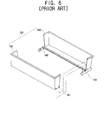
baking tray 104 is a rectangular container opening upwardly and is formed of a combination of afirst tray member 140 and asecond tray member 150. Aslit 160 is formed between thefirst tray member 140 and thesecond tray member 150 where thefirst tray member 140 and thesecond tray member 150 join together. - As shown in Figure 6, on each lower end of both side walls of the
first tray member 140 is aprotrusion rib 141 that is slidably coupled to a guide 114 (Figure 5) in thebaking space 110. Eachprotrusion rib 141 has a plurality of accommodatinggrooves 142 caved downwardly from the surface thereof. - On a lower end of both side walls of the
second tray member 150 are a plurality ofprojections 151 that protrude from the surface thereof and are movably accommodated in theaccommodating grooves 142 of theprotrusion ribs 141. - The upper end of the mixing bag is wound on the upper kneading
drum 111. The lower end of the mixing bag is wound on thelower drum 112 through the pair of kneading support members 113 and through theslit 160 formed on the bottom of thebaking tray 104. Further, during kneading, the mixing bag containing the ingredients for the dough is reciprocated upwardly and downwardly by the upper kneadingdrum 111 and thelower kneading drum 112. Thus, the ingredients for the dough contained in the mixing bag are kneaded between the pair of kneading support members 113 and thebaking tray 104. - After the kneading process is completed, the kneaded dough is placed in the
baking tray 104 and the mixing bag is removed, and then the dough is made into bread using aheater 106. - In the conventional bread maker, when the mixing bag moves upwardly through the
slit 160 of thebaking tray 104 during the kneading process, thesecond tray member 150 rotates upwardly along with the mixing bag and is rotated at a predetermined angle relative to theprotrusion ribs 141 because theprojections 151 of thesecond tray member 150 are movably accommodated in theaccommodating grooves 142 of theprotrusion ribs 141. - Further, when the mixing bag moves downwardly, the
second tray member 150, which has been rotated at the predetermined angle relative to theprotrusion ribs 141, moves downwardly with the mixing bag to an initial position, to form thebaking tray 104 having theslit 160 between thefirst tray member 140 and thesecond tray member 150. - However, as the
second tray member 150 rotates downwardly to the initial position, a noise is generated when thesecond tray member 150 impacts thefirst tray member 140. - It is an aim of preferred embodiments of the present invention to provide a bread maker for reducing a noise generated due to a collision between a fixed tray member and a movable tray member.
- According to an aspect of the present invention, there is provided a bread maker, comprising a main body having a baking space; kneading drums located at an upper part and a lower part in the baking space, the kneading drums holding opposite ends of a mixing bag; a movable tray member having a plurality of combining projections at opposite side walls thereof; a fixed tray member positioned opposite the movable tray member to form a slit through which the mixing bag passes; tray holders coupled to each end of the fixed tray member and the movable tray member, the tray holders fixedly supporting the fixed tray member, and having a plurality of guide grooves accommodating the combining projections to rotatably support the movable tray member; and anchoring prominences on the guide grooves adjacent to the fixed tray member, preventing the combining projections from breaking away from the guide grooves when the movable tray member rotates.
- The bread maker may further comprise guide members located at opposite side walls in the baking space, wherein the tray holders are slidably coupled to the guide members.
- Suitably, each anchoring prominence is located on an upper opening of a corresponding one of the guide grooves.
- According to another aspect of the present invention, there is provided a baking tray assembly for a bread maker, comprising tray holders having a plurality of guide grooves on a first end of each tray holder; a fixed tray having an open side and being fixedly attached to a second end of each tray holder; a movable tray having another open side and a plurality of projections on opposite side walls thereof, the guide grooves of the tray holders rotatably accommodating the projections of the movable tray, with the movable tray adjacent to the fixed tray and the open sides of the movable tray and the fixed tray facing one another to form a container; and anchors projecting into upper openings of the guide grooves adjacent to the fixed tray to prevent the projections from exiting the guide grooves when the movable tray rotates.
- According to the present invention in a third aspect, there is provided a baking tray assembly for a bread maker, comprising: means for fixedly attaching each end of a fixed tray to a first side of tray holders; means for rotatably attaching each end of a movable tray to a second side of the tray holders; and means for limiting a rotation angle of the movable tray as the movable tray rotates to reduce noise generated as the movable tray returns to an initial position and contacts the fixed tray.
- Further features of the present invention are set out in the appended claims.
- These together with other aspects and advantages which will be subsequently apparent, reside in the details of construction and operation as more fully hereinafter described and claimed, reference being had to the accompanying drawings forming a part thereof, wherein like numerals refer to like parts throughout.
- These and other objects and advantages of the present invention will become apparent and more readily appreciated from the following description of an embodiment thereof, by way of example only, taken in conjunction with the accompanying drawings, of which:
- Figure 1 is a perspective view of a bread maker according to an embodiment of the present invention;
- Figure 2 is an exploded perspective view of a baking tray shown in Figure 1;
- Figure 3 is an enlarged view of the baking tray of Figure 2;
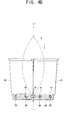
- Figures 4A and 4B are sectional views of the baking tray of Figure 1 taken along line IV-IV;
- Figure 5 is a perspective view of a conventional bread maker; and
- Figure 6 is an exploded perspective view of a baking tray shown in Figure 5.
-
- Hereinafter, an embodiment of the present invention will be described in detail with reference to the attached drawings, wherein the like reference numerals refer to the like elements throughout. The present invention may, however, be embodied in many different forms and should not be construed as being limited to the embodiments set forth herein; rather, this embodiment is provided so that the present disclosure will be thorough and complete, and will fully convey the concept of the invention to those skilled in the art.
- Referring to Figures 1 and 2, a bread maker according to an embodiment of the present invention includes a main body 1 having a
baking space 10, adoor 3 to open and close an opening formed at the front of the main body 1, and apanel 2 to manipulate the bread maker, which is provided at one side of the front of the main body 1. - At an upper part and a lower part of the
baking space 10 are an upper kneadingdrum 11 and alower kneading drum 12 for respectively winding an upper end and a lower end of a mixing bag 5 (Figure 4A) containing ingredients for dough. The upper kneadingdrum 11 and thelower kneading drum 12 are parallel to one another and rotate reciprocally. Between the upper kneadingdrum 11 and thelower kneading drum 12 are a pair of kneading supportingmembers 13 that prevent kneading ingredients in the mixing bag from moving out toward the upper kneadingdrum 11. - Also, between the kneading supporting
member 13 and thelower kneading drum 12 is abaking tray assembly 20 accommodating the kneaded ingredients, which may be withdrawn from thebaking space 10 and removed from the bread maker. - The
baking tray assembly 20 has abaking tray 30 including a fixedtray member 31 and amovable tray member 33, and a pair oftray holders 40 respectively coupled to end parts of the fixedtray member 31 and themovable tray member 33. - On a lower end of each side wall of the fixed
tray member 31 arefixing projections 32 that protrude from the surface thereof and engage the tray holders 40 (refer to Figure 4A). On a lower end of each side wall of themovable tray member 33 are combiningprojections 34 that protrude from the surface thereof and are movably coupled to thetray holders 40. - The
tray holders 40 are slidably coupled to guidemembers 14, which are provided at both side walls in thebaking space 10 and are opposite one another. - On an area of the
tray holders 40 adjacent to the fixedtray member 31 are fixedprojection accommodating grooves 41 for accommodating thefixing projections 32 of the fixed tray member 31 (Figure 4A). On an area of thetray holders 40 adjacent to themovable tray member 33 areguide grooves 42 that cave downwardly from the surface thereof for movably accommodating the combiningprojections 34 of themovable tray member 33. - As shown in Figure 3, on an upper opening area of each
guide groove 42 adjacent to the fixedtray member 31 is ananchoring prominence 43 for preventing the combiningprojections 34 that are accommodated in theguide groves 42 from breaking away from thetray holders 40. - Accordingly, the
fixing projections 32 of the fixedtray member 31 are coupled to the fixedprojection accommodating grooves 41, thereby mounting the fixedtray member 31 on thetray holders 40. Also, the combiningprojections 34 of themovable tray member 33 are movably inserted into theguide grooves 42 of thetray holders 40, thereby movably mounting themovable tray member 33 on thetray holders 40. - As described above, the fixed
tray member 31 and themovable tray member 33 face one another by use of thetray holders 40, thereby forming thebaking tray 30 having a rectangular container opening upwardly. Thus, on thebaking tray 30 is formed aslit 21 along the contact area of the fixedtray member 31 and themovable tray member 33. - The upper end of the mixing bag 5 (Figure 4A) is wound on the upper kneading
drum 11. The lower end of themixing bag 5 is wound on thelower kneading drum 12 through the pair of kneadingsupport members 13 and through theslit 21 formed on the bottom of thebaking tray 30. Further, during kneading, themixing bag 5 containing the ingredients for the dough reciprocates upwardly and downwardly according to rotation of the upper kneadingdrum 11 and thelower kneading drum 12. Thus, the ingredients for the dough contained in themixing bag 5 are kneaded between the kneadingsupport members 13 and thebaking tray 30. - After the kneading process is completed, the
mixing bag 5 is detached from the upper kneadingdrum 11 while thelower kneading drum 12 rotates. Themixing bag 5 passes through thekneading support members 13, and then passes through theslit 21. Further, when themixing bag 5 passes through theslit 21 of thebaking tray 30, the kneaded dough contained in themixing bag 5 does not pass through theslit 21 of thebaking tray 30 and, thus, is removed from themixing bag 5 and accommodated in thebaking tray 30. As themixing bag 5 passes through theslit 21, themixing bag 5 is wound on thelower kneading drum 12. Thus, the dough accommodated in thebaking tray 30 is made into bread by using aheater 16 in thebaking space 10. - Referring to Figures 4A and 4B, when the
mixing bag 5 containing the ingredients for the dough reciprocates upwardly and downwardly through theslit 21 and is kneaded between the kneadingsupport members 13 and thebaking tray 30 during the kneading process, themovable tray member 33 rotates clockwise and counterclockwise as themixing bag 5 moves upwardly and downwardly through theslit 21 because themovable tray member 33 is movably coupled to thetray holders 40. - For example, referring to Figure 4A, when the
mixing bag 5, which has a lower end that passes through theslit 21, moves upwardly, themovable tray member 33 rotates counterclockwise away from the fixedtray member 31 by pivoting around the leftmost combiningprojections 34. Thus, the combiningprojections 34 of themovable tray member 33 accommodated in theguide grooves 42 adjacent theslit 21 also rotate and are stopped by the anchoringprominences 43. Consequently, themovable tray member 33 rotates until the combiningprojections 34 engage the anchoringprominences 43 of theguide grooves 42. - On the other hand, referring to Figure 4B, when the mixing
bag 5 moves downwardly through theslit 21, themovable tray member 33 rotates clockwise around theleftmost combining projections 34 towards the fixedtray member 31, thereby allowing the combiningprojections 34 engaging the anchoringprominences 43 of theguide grooves 42 to move into theguide grooves 42 again. - According to the embodiment of the present invention described above, the
movable tray member 33 rotates away from the fixed tray member 3.1 as the mixingbag 5 moves upwardly, and the combiningprojections 34 accommodated in theguide grooves 42 that adjoin the fixedtray member 31 are prevented from breaking away by the anchoringprominences 43 of theguide grooves 42, thereby preventing themovable tray member 33 from rotating at an excessive angle relative to thetray holders 40. - Then, while the
movable tray member 33 returns to its initial position in which themovable tray member 33 and the fixedtray member 31 face one another to form thebaking tray 30, the impact of themovable tray member 33 on the fixedtray member 31 at the moment themovable tray member 33 contacts the fixedtray member 31 is minimized, thereby reducing the noise generated by the impact. - Although an embodiment of the present invention has been shown and described, it will be appreciated by those skilled in the art that changes may be made in this embodiment without departing from the principles and spirit of the invention, the scope of which is defined in the appended claims and their equivalents.
- The reader's attention is directed to all papers and documents which are filed concurrently with or previous to this specification in connection with this application and which are open to public inspection with this specification, and the contents of all such papers and documents are incorporated herein by reference.
- All of the features disclosed in this specification (including any accompanying claims, abstract and drawings), and/or all of the steps of any method or process so disclosed, may be combined in any combination, except combinations where at least some of such features and/or steps are mutually exclusive.
- Each feature disclosed in this specification (including any accompanying claims, abstract and drawings), may be replaced by alternative features serving the same, equivalent or similar purpose, unless expressly stated otherwise. Thus, unless expressly stated otherwise, each feature disclosed is one example only of a generic series of equivalent or similar features.
- The invention is not restricted to the details of the foregoing embodiment(s). The invention extends to any novel one, or any novel combination, of the features disclosed in this specification (including any accompanying claims, abstract and drawings), or to any novel one, or any novel combination, of the steps of any method or process so disclosed.
Claims (21)
- A bread maker, comprising:a main body (1) having a baking space (10);kneading drums (11, 12) located at an upper part and a lower part in the baking space (10), the kneading drums (11, 12) holding opposite ends of a mixing bag (5);a movable tray member (33) having a plurality of combining projections (34) at opposite side walls thereof;a fixed tray member (31) positioned opposite the movable tray member (33) to form a slit (21) through which the mixing bag (5) passes;tray holders (40) coupled to each end of the fixed tray member (31) and the movable tray member (33), respectively, the tray holders (40) fixedly supporting the fixed tray member (31), and having a plurality of guide grooves (42) accommodating the combining projections (34) to rotatably support the movable tray member (33); andanchoring prominences (43) on the guide grooves (42) adjacent to the fixed tray member (31), preventing the combining projections (34) from breaking away from the guide grooves (42) when the movable tray member (33) rotates.
- The bread maker according to claim 1, further comprising guide members (14) located at opposite side walls in the baking space (10), wherein the tray holders (40) are slidably coupled to the guide members (14).
- The bread maker according to claim 1 or claim 2, wherein each anchoring prominence (43) is located on an upper opening of the guide grooves (42).
- The bread maker according to any preceding claim, further comprising a control panel (2) in a front side of the main body (1) to allow a user to control the bread maker.
- The bread maker according to any preceding claim, further comprising a heater (16) in the baking space (10) to bake the bread.
- The bread maker according to any preceding claim, wherein the fixed tray member (31), the movable tray member (33), the tray holders (40), and the anchoring prominences (43) form a baking tray assembly (20) located between the kneading drums (11, 12), the baking tray assembly (20) holding kneaded dough for baking and being removable from the baking space (10).
- The bread maker according to any preceding claim, further comprising a plurality of fixing projections (32) at opposite side walls of the fixed tray member (31) and a plurality of fixed projection accommodating grooves (41) on an end of each tray holder (40) adjacent to the fixed tray member (31), the fixed projection accommodating grooves (41) receiving the fixing projections (32) to mount the fixed tray member (31) to the tray holders (40).
- The bread maker according to any preceding claim, wherein the guide grooves (42) cave downwardly from a surface thereof to movably accommodate the combining projections (34) of the movable tray member (33).
- The bread maker according to any preceding claim, wherein the movable tray member (33) faces the fixed tray member (31) to form a rectangular baking tray container for holding and baking the bread.
- The bread maker according to any preceding claim, wherein the slit (21) is formed along a contact area between the fixed tray member (31) and the movable tray member (33).
- The bread maker according to any preceding claim, wherein the kneading drums (11, 12) are parallel to one another and include an upper kneading drum (11) and a lower kneading drum (12), the upper kneading drum (11) receiving and winding an upper end of the mixing bag (5) and the lower kneading drum (12) receiving and winding a lower end of the mixing bag (5), the upper kneading drum (11) and the lower kneading drum (12) rotating reciprocally to respectively wind the upper end and the lower end of the mixing bag (5).
- The bread maker according to claim 11, further comprising kneading support members (13) between the upper kneading drum (11) and the lower kneading drum (12) to prevent kneading ingredients in the mixing bag (5) from moving out and toward the upper kneading drum (11).
- The bread maker according to claim 12, wherein the lower end of the mixing bag (5) is wound on the lower kneading drum (12) through the kneading support members (13) and the slit (21), and ingredients for dough contained in the mixing bag (5) are kneaded between the kneading support members (13) and the fixed tray member (31) and the movable tray member (33).
- The bread maker according to claim 13, wherein after the ingredients in the mixing bag (5) have been kneaded, the mixing bag (5) is detached from the upper kneading drum (11) while the lower kneading drum (12) continues rotating and winding the mixing bag, with the mixing bag (5) passing through the slit (21) to empty the kneaded ingredients from the mixing bag (5) into a container formed by the fixed tray member (31) and the movable tray member (33).
- The bread maker according to any one of claims 12-14, wherein when the mixing bag (5) reciprocates upwardly and downwardly through the slit (21) while the ingredients are kneaded, the movable tray member (33) rotates away from and towards the fixed tray member (31) as the mixing bag (5) moves upwardly and downwardly, respectively, the rotation of the movable tray member (33) away from the fixed tray member (31) being stopped when the combining projections (34) contact the anchoring prominences (43) of the tray holders (40) to limit an angle of rotation of the movable tray member (33), and the movable tray member (33) rotating towards the fixed tray member (31) to return to an initial position as the mixing bag (5) reciprocates downwardly through the slit (21), the limited angle of rotation reducing noise generated when the movable tray member (33) contacts the fixed tray member (31).
- A baking tray assembly (20) for a bread maker, comprising:tray holders (40) having a plurality of guide grooves (42) on a first end of each tray holder (40) ;a fixed tray (31) having an open side and being fixedly attached to a second end of each tray holder (40);a movable tray (33) having another open side and a plurality of projections (34) on opposite side walls thereof, the guide grooves (42) of the tray holders (40) rotatably accommodating the projections (34) of the movable tray (33), with the movable tray (33) adjacent to the fixed tray (31) and the open sides of the movable tray (33) and the fixed tray (31) facing one another to form a container; andanchors (43) projecting into upper openings of the guide grooves (42) adjacent to the fixed tray (31) to prevent the projections (34) from exiting the guide grooves (42) as the movable tray (33) rotates.
- The baking tray assembly according to claim 16, further comprising a plurality of fixing projections (32) at opposite side walls of the fixed tray (31) and a plurality of fixed grooves (41) on an end of each tray holder (40) adjacent to the fixed tray (31), the fixed grooves (41) receiving the fixing projections (32) to mount the fixed tray (31) to the tray holders (40).
- The baking tray assembly according to claim 16, wherein the guide grooves (42) cave downwardly from a surface thereof to movably accommodate the projections (34) of the movable tray member (33).
- The baking tray assembly according to claim 16, wherein a slit (21) is formed along a contact area between the fixed tray (31) and the movable tray (33).
- The baking tray assembly according to claim 19, wherein a mixing bag (5) containing ingredients for the bread reciprocates upwardly and downwardly through the slit (21) while the ingredients are kneaded, with the movable tray (33) rotating away from and towards the fixed tray member (31) as the mixing bag (5) moves upwardly and downwardly, respectively, the rotation of the movable tray (33) away from the fixed tray member (31) being stopped when the projections (34) contact the anchors (43) of the tray holders (40) to limit an angle of rotation of the movable tray (33), and the movable tray (33) rotating towards the fixed tray member (31) to return to an initial position as the mixing bag (5) reciprocates downwardly through the slit (21), the limited angle of rotation reducing noise generated when the movable tray (33) contacts the fixed tray member (31).
- A baking tray assembly (20) for a bread maker, comprising:means for fixedly attaching each end of a fixed tray (31) to a first side of tray holders (40);means for rotatably attaching each end of a movable tray (33) to a second side of the tray holders (40); andmeans for limiting a rotation angle of the movable tray (33) as the movable tray (33) rotates to reduce noise generated as the movable tray (33) returns to an initial position and contacts the fixed tray (31).
Applications Claiming Priority (2)
| Application Number | Priority Date | Filing Date | Title |
|---|---|---|---|
| KR2002042589 | 2002-07-19 | ||
| KR10-2002-0042589A KR100471073B1 (en) | 2002-07-19 | 2002-07-19 | Oven for baking bread |
Publications (2)
| Publication Number | Publication Date |
|---|---|
| EP1382254A1 true EP1382254A1 (en) | 2004-01-21 |
| EP1382254B1 EP1382254B1 (en) | 2006-11-22 |
Family
ID=29775033
Family Applications (1)
| Application Number | Title | Priority Date | Filing Date |
|---|---|---|---|
| EP02258730A Expired - Lifetime EP1382254B1 (en) | 2002-07-19 | 2002-12-18 | Improvements in and relating to bread makers |
Country Status (6)
| Country | Link |
|---|---|
| US (1) | US6935225B2 (en) |
| EP (1) | EP1382254B1 (en) |
| JP (1) | JP3634841B2 (en) |
| KR (1) | KR100471073B1 (en) |
| CN (1) | CN1212094C (en) |
| DE (1) | DE60216262T2 (en) |
Cited By (2)
| Publication number | Priority date | Publication date | Assignee | Title |
|---|---|---|---|---|
| EP1474981A1 (en) * | 2003-05-07 | 2004-11-10 | Samsung Electronics Co., Ltd. | Improvements in and relating to bread makers |
| WO2008040174A1 (en) * | 2006-09-19 | 2008-04-10 | Donglei Wang | Bread case used in bread making machine |
Families Citing this family (10)
| Publication number | Priority date | Publication date | Assignee | Title |
|---|---|---|---|---|
| KR20020047563A (en) * | 2000-12-13 | 2002-06-22 | 이계안 | Braking force controlled air brake system according to carrying capacity of auto mobile |
| KR20040096135A (en) * | 2003-05-07 | 2004-11-16 | 삼성전자주식회사 | Bake oven |
| KR20040096217A (en) * | 2003-05-07 | 2004-11-16 | 삼성전자주식회사 | Oven for baking bread |
| KR20040096137A (en) * | 2003-05-07 | 2004-11-16 | 삼성전자주식회사 | Baking machine and control method thereof |
| KR20040096218A (en) * | 2003-05-07 | 2004-11-16 | 삼성전자주식회사 | Bake oven |
| KR100850214B1 (en) * | 2007-05-23 | 2008-08-04 | 삼성전자주식회사 | Microscope and method of providing image data using the same. |
| GB2454924B (en) * | 2007-11-23 | 2011-12-14 | Dyson Technology Ltd | Support assembly |
| TW201138695A (en) * | 2010-01-15 | 2011-11-16 | Sanyo Electric Co | Automatic bread maker |
| CN104287642A (en) * | 2014-10-12 | 2015-01-21 | 朱海波 | Multipurpose device with baking sheet and bread functions |
| CN112075466A (en) * | 2020-09-07 | 2020-12-15 | 湖南省爱尚乐心食品有限公司 | Baking tray separating device for bread production |
Citations (6)
| Publication number | Priority date | Publication date | Assignee | Title |
|---|---|---|---|---|
| US4590850A (en) * | 1983-12-27 | 1986-05-27 | Heden Team A.G. | Apparatus for automatically making of food products such as bread, cakes and the like |
| WO1986003931A1 (en) * | 1984-12-27 | 1986-07-17 | Hedenteam A.G. | An apparatus for automatically making food products such as bread, cakes and the like |
| US4803086A (en) * | 1985-12-23 | 1989-02-07 | Heden-Team Aktiengesellschaft | Automatically making food products such as bread, cakes and the like |
| WO1992010100A1 (en) * | 1990-12-13 | 1992-06-25 | Heden-Team Ag | Automatic baking apparatus and mixbag therefor |
| WO1999025467A1 (en) * | 1997-11-17 | 1999-05-27 | Heden-Team Ag | Automatic baking apparatus and mixbag therefor |
| KR20020056628A (en) * | 2000-12-29 | 2002-07-10 | 윤종용 | Oven for baking bread |
Family Cites Families (10)
| Publication number | Priority date | Publication date | Assignee | Title |
|---|---|---|---|---|
| SE8207438D0 (en) * | 1982-12-28 | 1982-12-28 | Gunnar Hedenberg | KIT FOR MANUFACTURE OF FOOD PRODUCTS LIKE BREAD, COOKIES AND SIMILAR AND BAKING MACHINE FOR MANUFACTURE OF SAID PRODUCTS |
| US4550654A (en) * | 1983-04-01 | 1985-11-05 | Heden Team A.G. | Apparatus for automatic preparation of food products such as bread, cakes and the like |
| DE3479782D1 (en) | 1983-07-08 | 1989-10-26 | Hosiden Electronics Co | Automatic bread baking machine |
| KR900004466A (en) * | 1988-09-08 | 1990-04-12 | 이하다 가즈히꼬 | Cutter knife |
| US5146840A (en) * | 1989-11-22 | 1992-09-15 | Heden-Team Ag | Automatic baking apparatus and mixbag therefore |
| JP3104250B2 (en) | 1990-10-31 | 2000-10-30 | ソニー株式会社 | Magnetic recording method of digital image signal |
| JPH06327565A (en) | 1993-05-24 | 1994-11-29 | Matsushita Electric Ind Co Ltd | Automatic baking oven |
| KR0134664B1 (en) * | 1995-06-16 | 1998-04-18 | 구자홍 | Equipment for baking |
| KR100226691B1 (en) | 1996-10-31 | 1999-10-15 | 전주범 | A circuit for compensating a horizontal-deflection in a multi-mode monitor |
| US6321641B1 (en) * | 1999-07-02 | 2001-11-27 | Donglei Wang | Multi-chamber bread-baking machine |
-
2002
- 2002-07-19 KR KR10-2002-0042589A patent/KR100471073B1/en not_active Expired - Fee Related
- 2002-12-18 EP EP02258730A patent/EP1382254B1/en not_active Expired - Lifetime
- 2002-12-18 DE DE60216262T patent/DE60216262T2/en not_active Expired - Lifetime
- 2002-12-25 JP JP2002375598A patent/JP3634841B2/en not_active Expired - Fee Related
-
2003
- 2003-01-09 CN CNB031014674A patent/CN1212094C/en not_active Expired - Fee Related
- 2003-06-25 US US10/602,643 patent/US6935225B2/en not_active Expired - Fee Related
Patent Citations (6)
| Publication number | Priority date | Publication date | Assignee | Title |
|---|---|---|---|---|
| US4590850A (en) * | 1983-12-27 | 1986-05-27 | Heden Team A.G. | Apparatus for automatically making of food products such as bread, cakes and the like |
| WO1986003931A1 (en) * | 1984-12-27 | 1986-07-17 | Hedenteam A.G. | An apparatus for automatically making food products such as bread, cakes and the like |
| US4803086A (en) * | 1985-12-23 | 1989-02-07 | Heden-Team Aktiengesellschaft | Automatically making food products such as bread, cakes and the like |
| WO1992010100A1 (en) * | 1990-12-13 | 1992-06-25 | Heden-Team Ag | Automatic baking apparatus and mixbag therefor |
| WO1999025467A1 (en) * | 1997-11-17 | 1999-05-27 | Heden-Team Ag | Automatic baking apparatus and mixbag therefor |
| KR20020056628A (en) * | 2000-12-29 | 2002-07-10 | 윤종용 | Oven for baking bread |
Non-Patent Citations (1)
| Title |
|---|
| DATABASE WPI Section Ch Week 200305, Derwent World Patents Index; Class D11, AN 2003-055566, XP002259438 * |
Cited By (2)
| Publication number | Priority date | Publication date | Assignee | Title |
|---|---|---|---|---|
| EP1474981A1 (en) * | 2003-05-07 | 2004-11-10 | Samsung Electronics Co., Ltd. | Improvements in and relating to bread makers |
| WO2008040174A1 (en) * | 2006-09-19 | 2008-04-10 | Donglei Wang | Bread case used in bread making machine |
Also Published As
| Publication number | Publication date |
|---|---|
| KR100471073B1 (en) | 2005-03-10 |
| DE60216262T2 (en) | 2007-06-14 |
| CN1212094C (en) | 2005-07-27 |
| JP2004049880A (en) | 2004-02-19 |
| US20040060454A1 (en) | 2004-04-01 |
| DE60216262D1 (en) | 2007-01-04 |
| US6935225B2 (en) | 2005-08-30 |
| EP1382254B1 (en) | 2006-11-22 |
| JP3634841B2 (en) | 2005-03-30 |
| CN1468537A (en) | 2004-01-21 |
| KR20040008864A (en) | 2004-01-31 |
Similar Documents
| Publication | Publication Date | Title |
|---|---|---|
| EP1382254A1 (en) | Improvements in and relating to bread makers | |
| HU225386B1 (en) | Kneader and apparatus for producing food products from dough | |
| US20040050257A1 (en) | Bread maker | |
| EP1382253B1 (en) | Improvements in and relating to bread makers | |
| EP1474983A1 (en) | Improvements in and relating to bread makers | |
| EP1474981B1 (en) | Improvements in and relating to bread makers | |
| EP1474982B1 (en) | A bread maker | |
| US20040221735A1 (en) | Bread maker | |
| EP1474980B1 (en) | Bread maker | |
| JP3170560B2 (en) | Cooking device | |
| EP1475020B1 (en) | Bread maker | |
| KR100456586B1 (en) | Baking machine | |
| US20040221727A1 (en) | Bread maker | |
| EP1474987B1 (en) | Bread maker | |
| JPH0715227Y2 (en) | Paper tray for fax machine | |
| US20170325464A1 (en) | Auxiliary Material Accommodating Container and Automatic Bread Making Machine | |
| US20040221726A1 (en) | Bread maker | |
| KR20040096094A (en) | Baking machine | |
| JP2005333947A (en) | Feeding device for soup beverage |
Legal Events
| Date | Code | Title | Description |
|---|---|---|---|
| PUAI | Public reference made under article 153(3) epc to a published international application that has entered the european phase |
Free format text: ORIGINAL CODE: 0009012 |
|
| 17P | Request for examination filed |
Effective date: 20021218 |
|
| AK | Designated contracting states |
Kind code of ref document: A1 Designated state(s): AT BE BG CH CY CZ DE DK EE ES FI FR GB GR IE IT LI LU MC NL PT SE SI SK TR |
|
| AX | Request for extension of the european patent |
Extension state: AL LT LV MK RO |
|
| AKX | Designation fees paid |
Designated state(s): DE GB SE |
|
| 17Q | First examination report despatched |
Effective date: 20050503 |
|
| GRAP | Despatch of communication of intention to grant a patent |
Free format text: ORIGINAL CODE: EPIDOSNIGR1 |
|
| GRAS | Grant fee paid |
Free format text: ORIGINAL CODE: EPIDOSNIGR3 |
|
| GRAA | (expected) grant |
Free format text: ORIGINAL CODE: 0009210 |
|
| AK | Designated contracting states |
Kind code of ref document: B1 Designated state(s): DE GB SE |
|
| REG | Reference to a national code |
Ref country code: GB Ref legal event code: FG4D |
|
| REF | Corresponds to: |
Ref document number: 60216262 Country of ref document: DE Date of ref document: 20070104 Kind code of ref document: P |
|
| REG | Reference to a national code |
Ref country code: SE Ref legal event code: TRGR |
|
| RIN2 | Information on inventor provided after grant (corrected) |
Inventor name: PARK, JAE-RYONG Inventor name: LEE, TAE-UK,DAESUNG VILLA 201 Inventor name: SUNG, HAN-JUN,JUGONG APT, 909-202 Inventor name: LEE, JONG-WOOK |
|
| PLBE | No opposition filed within time limit |
Free format text: ORIGINAL CODE: 0009261 |
|
| STAA | Information on the status of an ep patent application or granted ep patent |
Free format text: STATUS: NO OPPOSITION FILED WITHIN TIME LIMIT |
|
| 26N | No opposition filed |
Effective date: 20070823 |
|
| PGFP | Annual fee paid to national office [announced via postgrant information from national office to epo] |
Ref country code: SE Payment date: 20091207 Year of fee payment: 8 |
|
| PGFP | Annual fee paid to national office [announced via postgrant information from national office to epo] |
Ref country code: GB Payment date: 20091216 Year of fee payment: 8 |
|
| PGFP | Annual fee paid to national office [announced via postgrant information from national office to epo] |
Ref country code: DE Payment date: 20091222 Year of fee payment: 8 |
|
| GBPC | Gb: european patent ceased through non-payment of renewal fee |
Effective date: 20101218 |
|
| REG | Reference to a national code |
Ref country code: SE Ref legal event code: EUG |
|
| PG25 | Lapsed in a contracting state [announced via postgrant information from national office to epo] |
Ref country code: SE Free format text: LAPSE BECAUSE OF NON-PAYMENT OF DUE FEES Effective date: 20101219 |
|
| REG | Reference to a national code |
Ref country code: DE Ref legal event code: R119 Ref document number: 60216262 Country of ref document: DE Effective date: 20110701 |
|
| PG25 | Lapsed in a contracting state [announced via postgrant information from national office to epo] |
Ref country code: GB Free format text: LAPSE BECAUSE OF NON-PAYMENT OF DUE FEES Effective date: 20101218 Ref country code: DE Free format text: LAPSE BECAUSE OF NON-PAYMENT OF DUE FEES Effective date: 20110701 |