EP1382237A1 - Feed conveyor/rock trap and header drive for an agricultural harvesting machine. - Google Patents
Feed conveyor/rock trap and header drive for an agricultural harvesting machine. Download PDFInfo
- Publication number
- EP1382237A1 EP1382237A1 EP03102044A EP03102044A EP1382237A1 EP 1382237 A1 EP1382237 A1 EP 1382237A1 EP 03102044 A EP03102044 A EP 03102044A EP 03102044 A EP03102044 A EP 03102044A EP 1382237 A1 EP1382237 A1 EP 1382237A1
- Authority
- EP
- European Patent Office
- Prior art keywords
- rotatable
- gear box
- input
- feeder
- harvesting machine
- Prior art date
- Legal status (The legal status is an assumption and is not a legal conclusion. Google has not performed a legal analysis and makes no representation as to the accuracy of the status listed.)
- Granted
Links
- 238000003306 harvesting Methods 0.000 title claims abstract description 29
- 239000011435 rock Substances 0.000 title description 27
- 238000002485 combustion reaction Methods 0.000 claims description 3
- 230000003466 anti-cipated effect Effects 0.000 description 7
- 230000005540 biological transmission Effects 0.000 description 7
- 239000000463 material Substances 0.000 description 6
- 241000196324 Embryophyta Species 0.000 description 4
- 235000013339 cereals Nutrition 0.000 description 3
- 238000010276 construction Methods 0.000 description 3
- 230000020169 heat generation Effects 0.000 description 2
- 229940090441 infed Drugs 0.000 description 2
- 244000068988 Glycine max Species 0.000 description 1
- 235000010469 Glycine max Nutrition 0.000 description 1
- 240000007594 Oryza sativa Species 0.000 description 1
- 235000007164 Oryza sativa Nutrition 0.000 description 1
- 241000209140 Triticum Species 0.000 description 1
- 235000021307 Triticum Nutrition 0.000 description 1
- 240000008042 Zea mays Species 0.000 description 1
- 235000005824 Zea mays ssp. parviglumis Nutrition 0.000 description 1
- 235000002017 Zea mays subsp mays Nutrition 0.000 description 1
- 210000000988 bone and bone Anatomy 0.000 description 1
- 235000005822 corn Nutrition 0.000 description 1
- 238000006073 displacement reaction Methods 0.000 description 1
- 238000012423 maintenance Methods 0.000 description 1
- 239000002184 metal Substances 0.000 description 1
- 230000000284 resting effect Effects 0.000 description 1
- 235000009566 rice Nutrition 0.000 description 1
Images




Classifications
-
- A—HUMAN NECESSITIES
- A01—AGRICULTURE; FORESTRY; ANIMAL HUSBANDRY; HUNTING; TRAPPING; FISHING
- A01D—HARVESTING; MOWING
- A01D69/00—Driving mechanisms or parts thereof for harvesters or mowers
-
- A—HUMAN NECESSITIES
- A01—AGRICULTURE; FORESTRY; ANIMAL HUSBANDRY; HUNTING; TRAPPING; FISHING
- A01D—HARVESTING; MOWING
- A01D41/00—Combines, i.e. harvesters or mowers combined with threshing devices
- A01D41/12—Details of combines
- A01D41/14—Mowing tables
- A01D41/142—Header drives
Definitions
- This invention relates generally to a drive for a feed conveyor, rock trap beater, and header of an agricultural harvesting machine such as a combine, and more particularly, to a drive for transferring rotatable power from a power source located on the main machine chassis to the feed conveyor, rock trap beater, and header, utilising a series of drive shafts, universal joints, and gear boxes, which provides more efficient power transmission, is less bulky and has improved durability and reliability and requires less maintenance than drives utilising belts and/or chains.
- limitations of the above-discussed power transmission arrangements include reduced power transmission efficiency resulting from the use of drive belts and/or chains; complex and bulky safety shielding required for the belts and/or chains, particularly when transmitting power across spaces to powered elements articulatable relative to the main chassis such as a feeder and header.
- Such shortcomings limit the header drive power potential and serviceability, and increase machine width, each of which can be disadvantageous.
- the front wheels of a combine are typically positioned beside and outwardly of the rearward end of the feed conveyor and the forward end of the main chassis frame of the combine, and in some instances, it may be desirable for the front wheels to be steerable.
- the lateral space between the wheel and the drive arrangement for the feed conveyor and header may additionally reduce the amount of space or clearance for turning the wheels, thereby limiting the steerability of the combine.
- an agricultural harvesting machine comprising: a main frame, a rotatable power source, mounted on said main frame, a feeder mounted to said main frame for pivotal movement relative thereto about a pivotal axis, and a drive comprising a first gear box mounted on said feeder for pivotal movement therewith and having a rotatable input for receiving power from said rotatable power source and at least one rotatable output, that is characterised in that said drive further comprises a plurality of drive shafts that are rotatably connected in end to end relation, one to the other, between said rotatable power source and said rotatable input of said first gear box.
- Such drive has the advantage of a better power transmission efficiency. It has the additional advantage that no complex and bulky safety shielding need to be foreseen.
- FIG 1 a self-propelled agricultural combine 10 movable in a forward direction, denoted by arrow F, for harvesting and separating crops, such as, but not limited to, grains including rice, wheat, soybeans, and corn, is shown.
- Combine 10 includes a forward end 12 carrying a conventional header 14 extending transversely there across in close proximity to the ground for gathering and cutting or otherwise separating crop materials or desired portions thereof from root structure thereof in the ground.
- the crop or plant or portions thereof are conveyed by header 14 to a feeder 16 which conveys the plant material to a separator 18 which separates the grain or other crops from the other plant materials and foreign material, the crops either being temporarily collected in a grain tank 20 on machine 10 or discharged to an accompanying wagon or truck (not shown).
- Combine 10 is propelled by a conventional power source such as an internal combustion engine 22 and a hydraulic and/or mechanical drive train (not shown) mounted on a main frame or chassis 24 of combine 10 in the well known conventional manner.
- Engine 22 is rotatably drivingly connected to a gear box 26 also located on chassis 24 by a hydraulic or mechanical drive (not shown), gear box 26 including a gear arrangement drivingly connected to a drive line 28 including a plurality of drive shafts 30 connected together in end to end relation and extending forwardly and downwardly to an output end 32 of one of the drive shafts 30 located at or closest to forward end 12 of chassis 24.
- feeder 16 is conventionally connected to forward end 12 for upward and downward pivotal movement relative to combine 10 about a generally horizontal pivotal axis 34, for positioning header 14 in any of a range of lower positions close to the ground, including a low position for releasing or disconnecting header 14 therefrom when resting on the ground or another location, and at least one elevated transport or road position, including a position sufficiently high for placing header 14 on a header cart or other transport or storage device (not shown).
- Header 14 illustrated in figure 1 is a non-limiting representative header including one or more augers, denoted at 36, gathering chains, sickles, and/or other rotatably driven elements (not shown) of well known, conventional construction and operation, for cutting, harvesting and gathering crops as combine 10 is moved in the forward direction denoted by arrow F and header 14 is in a harvesting position, such as shown in figure 1.
- Feeder 16 includes a housing 38 of sheet metal or other rigid construction containing and supporting a forwardly located rotatable drum or roller and a rearwardly and upwardly located series of sprockets 40 encircled by an endless belt or chains 42, including slats or other elements thereon operable for conveying the harvested and gathered crops from header 14 upwardly and rearwardly through housing 38 for discharge into an inlet or infeed region 44 of separator 18 on chassis 24 of combine 10.
- stones, rocks, and other hard, dense items or objects such as large sticks, logs, driftwood, large animal bones, portions of old fence posts, and the like, may be picked up by header 14, gathered by auger 36, and conveyed rearwardly and upwardly by chains 42 through housing 38 of feeder 16 toward infeed region 44 of separator 18.
- Separators, such as separator 18 depicted here, are precise devices, and include components that could be damaged by contact with such stones, rocks, and other hard objects.
- a feeder such as feeder 16 can optionally include a rock trap such as depicted at 46, at a location such as just rearwardly of and below sprockets 40, for receiving and holding such objects conveyed thereto by chains 42, before the objects would otherwise be infed into separator 18.
- a rock trap such as depicted at 46 may also optionally include a rotatable beater, denoted at 48, for separating the rocks or other hard objects from the softer plant material as it moves on to the separator 18, in a well known conventional manner.
- Beater 48 of rock trap 46, sprockets 40 of feeder 16, and auger 36 and the other rotatable elements of header 14 must receive adequately rotational power to perform their respective functions, particularly so as to provide a desired rate of infeed of crops into separator 18, without becoming jammed, clogged, and/or bogged down with crop material, leaves, and the like. It is well known to utilise a drive belt or belts and/or drive chains, in combination with one or more drive shafts, for rotatably driving a header, feeder, and/or rock trap beater, such as items 14, 16 and 48 here.
- belt drives and chain drives have numerous undesirable limitations, including, but not limited to, large space requirements, relatively lower power transmission efficiency for a given space occupied by the belt or chain drive and guards therefor, compared to a drive shaft under the same constraints.
- Belt and chain drives also generally generate more heat, and have greater service requirements.
- combine 10 utilises a solely shaft drive 50 for drivingly rotating the rotatable elements of header 14, feeder 16, and rock trap 46, including, but not limited to, auger 36, sickles, gathering chains or other apparatus (not shown) on header 14, sprockets 40 on feeder 16, and optionally beater 48 of rock trap 46.
- Drive 50 importantly includes a short input drive shaft 52 having an axial centre portion 54 disposed equidistant between an end thereof including a first universal joint 56 driveably connecting input drive shaft 52 to output end 32 of the closest drive shaft 30 on chassis 24, and an opposite end including a second universal joint 58 rotatably connecting input drive shaft 52 to a rotatable input 60 of a feeder and rock trap gear box 62 mounted on the near side of feeder 16.
- Universal joints 56 and 58 are each preferably a conventional Hooke or Cardan type universal joint having angularly related yokes connected respectively to the drive shafts and a cross link connecting the yokes together for pivotal movement one relative to the other.
- This short shaft, double universal joint arrangement enables the rotational velocity of driven input 60 to at least substantially match that of closest drive shaft 30, through an anticipated range of pivotal relationships between shaft 30 and input 60 corresponding to the pivotal positions of feeder 16 relative to combine 10.
- Feeder and rock trap gear box 62 is mounted to feeder 16 so as to be pivotally movable therewith about pivotal axis 34.
- Gear box 62 includes a rotatable output 64 extending transversely to the axis of input 60 and rotatably drivingly connected to beater 48, a transversely extending rotatable output 66 rotatably drivingly connected to sprockets 40, and an axially extending rotatable output 68 connected by a universal joint 70 to one end of a transfer shaft 72.
- Shaft 72 is preferably a telescoping type drive shaft for ease of assembly and disassembly and includes an opposite end connected by another universal joint 74 to a rotatable input 76 of a header gear box 78.
- Header gear box 78 is mounted on a forward end of feeder 16 and includes at least one transversely extending rotatable output 80 which is a conventional splined stub shaft or the like connectable in the normal and well known manner to a drive shaft (not shown) connected to auger 36 and the other rotatable elements of header 14 discussed above.
- feeder 16 is shown in a representative or selected middle position within a predetermined range of harvesting positions about pivotal axis 34 such that input drive shaft 52 and input 60 of gear box 62 are substantially coaxial with the closest drive shaft 30 of combine 10, as represented by axial line 82.
- axial line 82 intersects or very nearly intersects or substantially coincides with pivotal axis 34.
- Output 68 of gear box 62, transfer shaft 72, and input 76 of header gear case 78 are at least in the same plane as axial line 82, which relationship is advantageous for reasons discussed below.
- FIG 3 shows feeder 16 in a raised transport or header pick up position wherein the axis of input 60, denoted by axial line 84, is angularly offset from original axial line 82, as denoted by angle A.
- Another axial line 86 is shown in figure 3 beneath lines 82 and 84 and angularly related to line 82 by the angle B. This represents the axis of input 60 when feeder 16 is at a lower position just above or on the ground and at which the lower portions of feeder 16 can be separated from the header to allow disconnection and removal of the header from feeder 16.
- the feeder and header will typically not be operated at this orientation and this is not considered to be a harvesting or operating position.
- Figure 3 also shows a representative predetermined range of harvesting positions, denoted at C, for the axis of input 60 and feeder 16 when feeder 16 is positioned for positioning a header thereon such as header 14 for harvesting.
- Range C can vary for different field conditions, crop conditions, and headers, as well as operator preference, and other factors, and thus is not intended to be limiting. However, it should be understood that range C will typically fall within the positions denoted by axial lines 84 and 86, each of which is oriented about a 10° angle relative to axial line 82, as denoted by angles A and B, respectively. Thus, for representative purposes only, range C is depicted as having a value of about 8°.
- angles A and B are not intended to represent the upward and downward limits of movement of feeder 16.
- a typical feeder such as feeder 16 shown will have a range of movement of about 26° or so, mostly in the upward direction from axis 82.
- FIGs 4, 5, 6, and 7, schematic representations of input drive shaft 52, universal joints 56 and 58, end 32 of closest drive shaft 30, and input 60, are shown when those items are in the above discussed positions.
- drive shaft 52, universal joints 56 and 58, end 32 of closest drive shaft 30, and input 60 are shown coaxially aligned along axial line 82, as in Figs. 1 and 2.
- axial line 82 intersects pivotal axis 34, such that axial centre portion 54 of drive shaft 52 is substantially coincident with pivotal axis 34.
- Alignment of shafts 30 and 52 with input 60 represents the optimal power transmission relationship, with minimised power loss, heat generation and wear in universal joints 56 and 58, and loading on shaft 52.
- shaft 52 has a length between the pivotal axes of joints 56 and 58, denoted at G.
- FIG 5 a similar schematic shows input 60 pivotally displaced upwardly about pivot axis 34 by about 10°, which represents a typical high pivotal position of feeder 16 shown in figure 3.
- first and second universal joints 56 and 58 are each pivoted an equal amount of about 5°, as denoted by angles D and E, which is about half the angular displacement of input 60.
- angles D and E which is about half the angular displacement of input 60.
- the header and feeder would be operated when in a high position such as this only rarely, for instance if combine 10 were crossing a waterway or other depression in a field, such that it is not anticipated to be a problem.
- input 60 is shown pivoted downwardly about pivotal axis 34 by an amount of about 10° which places the axis there through at or just above axial line 86 in figure 3. This corresponds to a position wherein header 14 will be very close to the ground and not likely operating.
- centre portion 54 of drive shaft 52 is located just below pivotal axis 34 and universal joints 56 and 58 are each pivoted by an amount of about one-half the 10° angle or about 5° as denoted by angles D and E. Again, this represents one of the positions wherein a high anticipated tensile loading condition would be present were the drive to be rotating.
- input 60 is shown pivoted downwardly about pivotal axis 34 by an amount of about 4° from the centre or middle range position shown in figure 2, which places the axis there through at a position within a lower portion of the range C in figure 3. This corresponds to a position of header 14 and feeder 16 in an anticipated lower harvesting position, just below that illustrated in figure 1.
- centre portion 54 of drive shaft 52 is located just below pivotal axis 34 and universal joints 56 and 58 are each pivoted by an amount of about one-half the 4° angle or about 2° each as denoted by angles D and E.
- Input 60 includes a first bevel gear 88 mounted thereon for rotation therewith, enmeshed with a second bevel gear 90 connected to an input of an optional slip clutch 92.
- An output 94 of slip clutch 92 includes a gear 96 enmeshed with output gears 98 and 100 which are mounted to outputs 64 and 66, respectively, drivingly connected to beater 48 of rock trap 46 and sprockets 40 of feeder 16, respectively.
- Output 68 is mounted to and coaxial with input 60 and is connected by a transfer shaft 72 to input 76 of header gear box 78, as explained above.
- Input 76 includes a bevel gear 102 mounted thereon for rotation therewith enmeshed with a bevel gear 104 mounted on output 80 for rotation therewith, output 80 being connected to the rotatable elements of header 14, as explained above.
- sprockets 40 of feeder 16 and beater 48 of rock trap 46 are jointly driven in the same direction, as desired and required, such that there is no need for a separate rock trap beater drive. Additionally, overload protection is provided to both outputs 64 and 66 using only one slip clutch, which provides torque overload protection in either forward or reverse directions of operation. Further, by the axial alignment of input 60 and output 68, sufficient lateral or sideward compactness is achieved.
- outputs 64 and 66 are interchangeable and gear box 62 is shown optionally configured to eliminate output 64 for rock trap beater 48, for applications wherein a rock trap beater is not required or desired.
- gear box 62 In configure gear box 62 in this manner, output 64 and gear 98 shown in figure 8 are not installed, or are removed, and output 66 and gear 100 are used instead at that location, and the opening in gear box 62 for output 66 shown in figure 8 is suitably plugged.
- an alternative feeder and rock trap gear box 106 for drive 50 which provides a sideward offset between input 60 and output 68 extending to header gear box 78.
- input 60 still includes bevel gear 88 enmeshed with a bevel gear 90 for rotatably driving outputs 64 and 66, but instead of direct connection to output 68 and thus to transfer shaft 72 as above, input 60 includes a gear 108 enmeshed with a gear 111 on output 68 connected to transfer shaft 72. This enables output 68 to be offset sidewardly and inwardly of input 60 as shown in figure 12.
- gear box 106 is shown mounted on the side of feeder 16 beside a forward steerable wheel 116 of combine 10, wheel 116 being shown turned to the left.
- Input 60 is connected to and aligned with forwardmost drive shaft 30 by drive shaft 52 and universal joints 56 and 58 as above.
- Drive shaft 52 is centred on pivotal axis 34 of feeder 16.
- Drive shaft 30 is located beside and outside of a forward frame post 118 of combine 10.
- output 68 of gear box 106 from input 60 in the inward sideward direction, a space or clearance is provided to allow turning wheel 116 to a position such as shown, without rubbing or otherwise contacting transfer shaft 72.
- bevel gear 90 is mounted on a shaft of a transverse drive line 110 optionally including a slip clutch 92.
- Drive line 110 additionally includes gears 112 and 114 enmeshed with gears 98 and 100, respectively, on outputs 64 and 66 connected to rock trap beater 48 and sprockets 40, as above. Because separate gears 112 and 114 are utilised for driving outputs 64 and 66, those outputs may be driven at different, selectable ratios to the speed of drive line 110. This arrangement could likewise be used in gear box 62. Versatility is also provided to allow use of gear case 106 for driving just feeder 16, without the optional rock trap beater, by utilising output 66 in place of output 64 similarly as described above.
- drive shaft 52 is indicated as being relatively short.
- drive shaft 52 will have a length G as shown in figure 4 of less than about 300 mm, and more preferably between about 150 to 250 mm, to provide the advantages set forth above.
Landscapes
- Life Sciences & Earth Sciences (AREA)
- Environmental Sciences (AREA)
- Harvester Elements (AREA)
Abstract
- a main frame (24);
- a rotatable power source (22), mounted on said main frame (24);
- a feeder (16) mounted to said main frame (24) for pivotal movement relative thereto about a pivotal axis (34); and
- a drive comprising a first gear box (62) mounted on said feeder (16) for pivotal movement therewith and having a rotatable input (60) for receiving power from said rotatable power source (22) and at least one rotatable output (64,66,68);
Description
- This invention relates generally to a drive for a feed conveyor, rock trap beater, and header of an agricultural harvesting machine such as a combine, and more particularly, to a drive for transferring rotatable power from a power source located on the main machine chassis to the feed conveyor, rock trap beater, and header, utilising a series of drive shafts, universal joints, and gear boxes, which provides more efficient power transmission, is less bulky and has improved durability and reliability and requires less maintenance than drives utilising belts and/or chains.
- It is well known to utilise drive shafts, universal joints, and gear boxes in various combinations with drive belts and/or chains, for transferring power from a power source on the main chassis or frame of a combine, such as an internal combustion engine, to a feed conveyor, rock trap beater, and/or header on the forward end of the combine. Reference in this regard, US-A-3,535,859, which discloses a header construction for a combine having a drive system including a combination of drive shafts, universal joints, and a gear box, which receives power from a belt drive. Reference also US-A-5,904,032, which discloses a belt driven header and feed conveyor which receives power through a drive shaft and universal joints.
- However, limitations of the above-discussed power transmission arrangements include reduced power transmission efficiency resulting from the use of drive belts and/or chains; complex and bulky safety shielding required for the belts and/or chains, particularly when transmitting power across spaces to powered elements articulatable relative to the main chassis such as a feeder and header. Such shortcomings limit the header drive power potential and serviceability, and increase machine width, each of which can be disadvantageous.
- Additionally, the front wheels of a combine are typically positioned beside and outwardly of the rearward end of the feed conveyor and the forward end of the main chassis frame of the combine, and in some instances, it may be desirable for the front wheels to be steerable. As a result, the lateral space between the wheel and the drive arrangement for the feed conveyor and header may additionally reduce the amount of space or clearance for turning the wheels, thereby limiting the steerability of the combine.
- Thus, what is sought is a drive for the feed conveyor, header, and optionally a rock trap beater, of an agricultural combine which overcomes many of the shortcomings and limitations discussed above.
- It is an object of the present invention to provide a rotatable drive for a feeder and a header of an agricultural combine for connecting spaced rotatable elements on the feeder and the header to a rotatable power source on a chassis of the combine.
- It is a further object of the invention to provide an output and drive shaft or transfer shaft connecting a first gearbox to a second gear box, to offset sidewardly toward the side of the feeder from the input of the first gear box, so as to provide a space or clearance for turning of an adjacent steerable wheel of the combine.
- According to the invention, there is provided an agricultural harvesting machine comprising: a main frame, a rotatable power source, mounted on said main frame, a feeder mounted to said main frame for pivotal movement relative thereto about a pivotal axis, and a drive comprising a first gear box mounted on said feeder for pivotal movement therewith and having a rotatable input for receiving power from said rotatable power source and at least one rotatable output, that is characterised in that said drive further comprises a plurality of drive shafts that are rotatably connected in end to end relation, one to the other, between said rotatable power source and said rotatable input of said first gear box.
- Such drive has the advantage of a better power transmission efficiency. It has the additional advantage that no complex and bulky safety shielding need to be foreseen.
- An embodiment of the present invention will now be described in further detail, by way of example, with reference to the following drawings, in which :
- figure 1 is a simplified side elevational view of an agricultural combine including a drive for a feeder, a rock trap beater, and a header of the combine;
- figure 2 is a simplified schematic side elevational representation of the drive of figure 1;
- figure 3 is another simplified schematic representation of the drive of figure 1, shown pivoted to an alternative position;
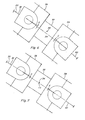
- figure 4 is an enlarged simplified side elevational schematic representation of elements of the drive of figure 1;
- figure 5 is another enlarged simplified side elevational schematic representation of the elements of figure 4 in one alternative position;
- figure 6 is another enlarged simplified side elevational schematic representation of the elements of figure 4 in another alternative position;
- figure 7 is another enlarged simplified side elevational schematic representation of the elements of figure 4 in another alternative position;
- figure 8 is a simplified top schematic representation of the drive of figure 1;
- figure 9 is a simplified top schematic representation of an alternative drive for the feed conveyor and header of the combine of figure 1;
- figure 10 is a simplified schematic representation of the alternative drive of figure 9 for the feed conveyer and header of the combine of figure 1;
- figure 11 is a simplified top schematic representation of another alternative drive for the feed conveyor, rock trap, and header of the combine of figure 1; and
- figure 12 is a simplified top schematic representation of the forward end of the combine of figure 1 and the drive of figure 11, with forward steerable drive wheels of the combine shown turned.
-
- Referring now to the drawings, in figure 1 a self-propelled
agricultural combine 10 movable in a forward direction, denoted by arrow F, for harvesting and separating crops, such as, but not limited to, grains including rice, wheat, soybeans, and corn, is shown.Combine 10 includes aforward end 12 carrying aconventional header 14 extending transversely there across in close proximity to the ground for gathering and cutting or otherwise separating crop materials or desired portions thereof from root structure thereof in the ground. The crop or plant or portions thereof are conveyed byheader 14 to afeeder 16 which conveys the plant material to aseparator 18 which separates the grain or other crops from the other plant materials and foreign material, the crops either being temporarily collected in agrain tank 20 onmachine 10 or discharged to an accompanying wagon or truck (not shown). - Combine 10 is propelled by a conventional power source such as an
internal combustion engine 22 and a hydraulic and/or mechanical drive train (not shown) mounted on a main frame orchassis 24 of combine 10 in the well known conventional manner.Engine 22 is rotatably drivingly connected to agear box 26 also located onchassis 24 by a hydraulic or mechanical drive (not shown),gear box 26 including a gear arrangement drivingly connected to adrive line 28 including a plurality ofdrive shafts 30 connected together in end to end relation and extending forwardly and downwardly to anoutput end 32 of one of thedrive shafts 30 located at or closest to forwardend 12 ofchassis 24. - Referring also to figures 2 and 3,
feeder 16 is conventionally connected to forwardend 12 for upward and downward pivotal movement relative to combine 10 about a generally horizontalpivotal axis 34, forpositioning header 14 in any of a range of lower positions close to the ground, including a low position for releasing or disconnectingheader 14 therefrom when resting on the ground or another location, and at least one elevated transport or road position, including a position sufficiently high for placingheader 14 on a header cart or other transport or storage device (not shown).Header 14 illustrated in figure 1 is a non-limiting representative header including one or more augers, denoted at 36, gathering chains, sickles, and/or other rotatably driven elements (not shown) of well known, conventional construction and operation, for cutting, harvesting and gathering crops ascombine 10 is moved in the forward direction denoted by arrow F andheader 14 is in a harvesting position, such as shown in figure 1.Feeder 16 includes ahousing 38 of sheet metal or other rigid construction containing and supporting a forwardly located rotatable drum or roller and a rearwardly and upwardly located series ofsprockets 40 encircled by an endless belt orchains 42, including slats or other elements thereon operable for conveying the harvested and gathered crops fromheader 14 upwardly and rearwardly throughhousing 38 for discharge into an inlet or infeedregion 44 ofseparator 18 onchassis 24 ofcombine 10. From time to time, stones, rocks, and other hard, dense items or objects such as large sticks, logs, driftwood, large animal bones, portions of old fence posts, and the like, may be picked up byheader 14, gathered by auger 36, and conveyed rearwardly and upwardly bychains 42 throughhousing 38 offeeder 16 towardinfeed region 44 ofseparator 18. Separators, such asseparator 18 depicted here, are precise devices, and include components that could be damaged by contact with such stones, rocks, and other hard objects. To reduce the number of such hard objects infed toseparator 18, particularly larger objects, a feeder such asfeeder 16 can optionally include a rock trap such as depicted at 46, at a location such as just rearwardly of and belowsprockets 40, for receiving and holding such objects conveyed thereto bychains 42, before the objects would otherwise be infed intoseparator 18. A rock trap such as depicted at 46 may also optionally include a rotatable beater, denoted at 48, for separating the rocks or other hard objects from the softer plant material as it moves on to theseparator 18, in a well known conventional manner. -
Beater 48 ofrock trap 46,sprockets 40 offeeder 16, and auger 36 and the other rotatable elements ofheader 14 must receive adequately rotational power to perform their respective functions, particularly so as to provide a desired rate of infeed of crops intoseparator 18, without becoming jammed, clogged, and/or bogged down with crop material, leaves, and the like. It is well known to utilise a drive belt or belts and/or drive chains, in combination with one or more drive shafts, for rotatably driving a header, feeder, and/or rock trap beater, such asitems - Referring also to figures 2 and 3, to eliminate the above discussed disadvantages, combine 10 utilises a solely
shaft drive 50 for drivingly rotating the rotatable elements ofheader 14,feeder 16, androck trap 46, including, but not limited to, auger 36, sickles, gathering chains or other apparatus (not shown) onheader 14,sprockets 40 onfeeder 16, and optionally beater 48 ofrock trap 46.Drive 50 importantly includes a shortinput drive shaft 52 having anaxial centre portion 54 disposed equidistant between an end thereof including a firstuniversal joint 56 driveably connectinginput drive shaft 52 to outputend 32 of theclosest drive shaft 30 onchassis 24, and an opposite end including a seconduniversal joint 58 rotatably connectinginput drive shaft 52 to arotatable input 60 of a feeder and rocktrap gear box 62 mounted on the near side offeeder 16.Universal joints input 60 to at least substantially match that ofclosest drive shaft 30, through an anticipated range of pivotal relationships betweenshaft 30 andinput 60 corresponding to the pivotal positions offeeder 16 relative to combine 10. Feeder and rocktrap gear box 62 is mounted tofeeder 16 so as to be pivotally movable therewith aboutpivotal axis 34.Gear box 62 includes arotatable output 64 extending transversely to the axis ofinput 60 and rotatably drivingly connected tobeater 48, a transversely extendingrotatable output 66 rotatably drivingly connected tosprockets 40, and an axially extendingrotatable output 68 connected by auniversal joint 70 to one end of atransfer shaft 72. Shaft 72 is preferably a telescoping type drive shaft for ease of assembly and disassembly and includes an opposite end connected by anotheruniversal joint 74 to arotatable input 76 of aheader gear box 78.Header gear box 78 is mounted on a forward end offeeder 16 and includes at least one transversely extendingrotatable output 80 which is a conventional splined stub shaft or the like connectable in the normal and well known manner to a drive shaft (not shown) connected to auger 36 and the other rotatable elements ofheader 14 discussed above. - Referring more particularly to figures 1 and 2,
feeder 16 is shown in a representative or selected middle position within a predetermined range of harvesting positions aboutpivotal axis 34 such thatinput drive shaft 52 andinput 60 ofgear box 62 are substantially coaxial with theclosest drive shaft 30 ofcombine 10, as represented byaxial line 82. Importantly, in this position,axial line 82 intersects or very nearly intersects or substantially coincides withpivotal axis 34.Output 68 ofgear box 62,transfer shaft 72, andinput 76 ofheader gear case 78 are at least in the same plane asaxial line 82, which relationship is advantageous for reasons discussed below. - Figure 3 shows
feeder 16 in a raised transport or header pick up position wherein the axis ofinput 60, denoted byaxial line 84, is angularly offset from originalaxial line 82, as denoted by angle A. Anotheraxial line 86 is shown in figure 3 beneathlines line 82 by the angle B. This represents the axis ofinput 60 whenfeeder 16 is at a lower position just above or on the ground and at which the lower portions offeeder 16 can be separated from the header to allow disconnection and removal of the header fromfeeder 16. The feeder and header will typically not be operated at this orientation and this is not considered to be a harvesting or operating position. Figure 3 also shows a representative predetermined range of harvesting positions, denoted at C, for the axis ofinput 60 andfeeder 16 whenfeeder 16 is positioned for positioning a header thereon such asheader 14 for harvesting. Range C can vary for different field conditions, crop conditions, and headers, as well as operator preference, and other factors, and thus is not intended to be limiting. However, it should be understood that range C will typically fall within the positions denoted byaxial lines axial line 82, as denoted by angles A and B, respectively. Thus, for representative purposes only, range C is depicted as having a value of about 8°. Here, it should be noted that angles A and B are not intended to represent the upward and downward limits of movement offeeder 16. For instance, a typical feeder such asfeeder 16 shown will have a range of movement of about 26° or so, mostly in the upward direction fromaxis 82. - Due to the combination of the relatively short length of
input drive shaft 52, the use ofuniversal joints axial centre portion 54 intersecting or nearly intersecting or substantially coincident withpivotal axis 34 whenfeeder 16 is in a central or middle harvesting position, whenfeeder 16 is pivotally moved upwardly or downwardly aboutpivotal axis 34, particularly within range C,universal joints feeder 16 is pivoted. As a result of this combination it has been found that there are relatively small tensile loads exerted onshaft 52 urging it to elongate or otherwise change the distance betweenuniversal joints shaft 52 is rotated. These loads are easily accommodated by allowing universal joint 58 to slide in the axial direction oninput 60, such thatinput shaft 52 is not required to be a telescoping shaft, and little or no additional power loss, heat build-up, increase in wear, or velocity variation of the driven shaft, are experienced. - As illustrations of this desirable result, in figures 4, 5, 6, and 7, schematic representations of
input drive shaft 52,universal joints closest drive shaft 30, andinput 60, are shown when those items are in the above discussed positions. In figure 4, driveshaft 52,universal joints closest drive shaft 30, andinput 60 are shown coaxially aligned alongaxial line 82, as in Figs. 1 and 2. In this position,axial line 82 intersectspivotal axis 34, such thataxial centre portion 54 ofdrive shaft 52 is substantially coincident withpivotal axis 34. Alignment ofshafts input 60 represents the optimal power transmission relationship, with minimised power loss, heat generation and wear inuniversal joints shaft 52. In this aligned orientation,shaft 52 has a length between the pivotal axes ofjoints - In figure 5, a similar
schematic shows input 60 pivotally displaced upwardly aboutpivot axis 34 by about 10°, which represents a typical high pivotal position offeeder 16 shown in figure 3. Withinput 60 in this position, due to the short length ofdrive shaft 52,axial centre portion 54 thereof is displaced a small distance abovepivotal axis 34, and first and seconduniversal joints input 60. This illustrates a position wherein a higher anticipated tensile loading condition would be present were the drive to be rotating. However, it is expected that the header and feeder would be operated when in a high position such as this only rarely, for instance ifcombine 10 were crossing a waterway or other depression in a field, such that it is not anticipated to be a problem. - In figure 6,
input 60 is shown pivoted downwardly aboutpivotal axis 34 by an amount of about 10° which places the axis there through at or just aboveaxial line 86 in figure 3. This corresponds to a position whereinheader 14 will be very close to the ground and not likely operating. In this instance,centre portion 54 ofdrive shaft 52 is located just belowpivotal axis 34 anduniversal joints - In figure 7,
input 60 is shown pivoted downwardly aboutpivotal axis 34 by an amount of about 4° from the centre or middle range position shown in figure 2, which places the axis there through at a position within a lower portion of the range C in figure 3. This corresponds to a position ofheader 14 andfeeder 16 in an anticipated lower harvesting position, just below that illustrated in figure 1. In this instance,centre portion 54 ofdrive shaft 52 is located just belowpivotal axis 34 anduniversal joints shaft 52 urging elongation would be sufficiently low, even as the drive is rotated under heavy loads anticipated during harvesting, so as to be negligible and adequately resisted or absorbed by normal elongation of and/or endplay in the components of the drive. - Thus, during operation of the header such as
header 14 andfeeder 16, whetherfeeder 16 is pivoted aboutpivot axis 34 upwardly or downwardly within an anticipated range of pivotal harvesting positions, generally denoted by range C in figure 3,universal joints shaft 52 will be subjected to only minimal elongation or tensile loading, such that power transmission capability is preserved, and heat generation and wear are minimised. - Turning to figure 8, a simplified schematic top representation of feeder and rock
trap gear box 62,transfer shaft 72, andheader gear box 78 is shown.Input 60 includes afirst bevel gear 88 mounted thereon for rotation therewith, enmeshed with asecond bevel gear 90 connected to an input of an optional slip clutch 92. Anoutput 94 of slip clutch 92 includes agear 96 enmeshed with output gears 98 and 100 which are mounted tooutputs beater 48 ofrock trap 46 andsprockets 40 offeeder 16, respectively.Output 68 is mounted to and coaxial withinput 60 and is connected by atransfer shaft 72 to input 76 ofheader gear box 78, as explained above.Input 76 includes abevel gear 102 mounted thereon for rotation therewith enmeshed with abevel gear 104 mounted onoutput 80 for rotation therewith,output 80 being connected to the rotatable elements ofheader 14, as explained above. - Using the arrangement of figure 8,
sprockets 40 offeeder 16 andbeater 48 ofrock trap 46 are jointly driven in the same direction, as desired and required, such that there is no need for a separate rock trap beater drive. Additionally, overload protection is provided to bothoutputs input 60 andoutput 68, sufficient lateral or sideward compactness is achieved. - Turning to figures 9 and 10, outputs 64 and 66 are interchangeable and
gear box 62 is shown optionally configured to eliminateoutput 64 forrock trap beater 48, for applications wherein a rock trap beater is not required or desired. To configuregear box 62 in this manner,output 64 andgear 98 shown in figure 8 are not installed, or are removed, andoutput 66 andgear 100 are used instead at that location, and the opening ingear box 62 foroutput 66 shown in figure 8 is suitably plugged. This will requirepositioning sprockets 40 more rearwardly infeeder 16, in the position previously occupied bybeater 48, necessitating that a longer belt orchain 42 be used due to the greater span, such that too large of a gap is not present betweensprockets 40 and the infeed region of separator 18 (figure 1). - Turning to figures 11 and 12, an alternative feeder and rock
trap gear box 106 fordrive 50 is shown which provides a sideward offset betweeninput 60 andoutput 68 extending toheader gear box 78. In this arrangement,input 60 still includesbevel gear 88 enmeshed with abevel gear 90 for rotatably drivingoutputs output 68 and thus to transfershaft 72 as above,input 60 includes agear 108 enmeshed with a gear 111 onoutput 68 connected to transfershaft 72. This enablesoutput 68 to be offset sidewardly and inwardly ofinput 60 as shown in figure 12. Referring more particularly to figure 12,gear box 106 is shown mounted on the side offeeder 16 beside a forwardsteerable wheel 116 ofcombine 10,wheel 116 being shown turned to the left.Input 60 is connected to and aligned withforwardmost drive shaft 30 bydrive shaft 52 anduniversal joints shaft 52 is centred onpivotal axis 34 offeeder 16. Driveshaft 30 is located beside and outside of aforward frame post 118 ofcombine 10. Advantageously, by offsettingoutput 68 ofgear box 106 frominput 60 in the inward sideward direction, a space or clearance is provided to allowturning wheel 116 to a position such as shown, without rubbing or otherwise contactingtransfer shaft 72. - Returning to figure 11,
bevel gear 90 is mounted on a shaft of atransverse drive line 110 optionally including aslip clutch 92.Drive line 110 additionally includesgears gears outputs rock trap beater 48 andsprockets 40, as above. Becauseseparate gears outputs drive line 110. This arrangement could likewise be used ingear box 62. Versatility is also provided to allow use ofgear case 106 for driving justfeeder 16, without the optional rock trap beater, by utilisingoutput 66 in place ofoutput 64 similarly as described above. - As noted above
input drive shaft 52 is indicated as being relatively short. Preferably driveshaft 52 will have a length G as shown in figure 4 of less than about 300 mm, and more preferably between about 150 to 250 mm, to provide the advantages set forth above.
Claims (13)
- An agricultural harvesting machine (10) comprising:characterised in that said drive further comprises a plurality of drive shafts (30,52) that are rotatably connected in end to end relation, one to the other, between said rotatable power source (22) and said rotatable input (60) of said first gear box (62).a main frame (24);a rotatable power source (22), mounted on said main frame (24);a feeder (16) mounted to said main frame (24) for pivotal movement relative thereto about a pivotal axis (34); anda drive comprising a first gear box (62) mounted on said feeder (16) for pivotal movement therewith and having a rotatable input (60) for receiving power from said rotatable power source (22) and at least one rotatable output (64,66,68);
- An agricultural harvesting machine (10) according to claim 1, characterised in that one of said drive shafts (52) is rotatably connected by universal joints (56,58) on opposite ends thereof to another of said drive shafts (30) and to said input (60) of said first gear box (62), respectively, and has an axial centre portion (54) located substantially coincident with said pivotal axis (34).
- An agricultural harvesting machine (10) according to claims 1 or 2, characterised in that said at least one rotatable output (64,66) is rotatably connected to said input (60) of said first gear box (62) and to at least one rotatable conveyor element (40,48).
- An agricultural harvesting machine (10) according to claim 3, characterised in that said first gear box (62) comprises first and second rotatable outputs (64,66); each one of which is rotatably connected to said input (60) of said first gear box (62) with the first output (64) further also being rotatably connected to a rotatable beater (48) in said feeder (16) and the second output (66) also being rotatably connected to drive sprockets (40) of an endless feeder conveyor (42) in said feeder (12).
- An agricultural harvesting machine (10) according to claim 4, characterised in that said first rotatable output (64) is located at a predetermined position on said first gear box (62) and is removable therefrom and replaceable by said second rotatable output (66).
- An agricultural harvesting machine (10) according to claims 4 or 5, characterised in that said first and second rotatable outputs (64,66) are interchangeably positioned on said first gear box (62).
- An agricultural harvesting machine (10) according to any of the preceding claims, characterised in that said at least one rotatable output (64,66) is rotatably connected to said input (60) of said first gear box (62) by a drive line including a slip clutch (92).
- An agricultural harvesting machine (10) according to any of the claims 4 to 6, characterised in that said first gear box (62) comprises a third rotatable output (68), which is rotatably connected to said input (60) of said first gear box (62) and to a rotatable input (76) of a second gear box (78), also mounted on said feeder (16) for pivotal movement therewith.
- An agricultural harvesting machine (10) according to claim 8, characterised in that said input (60) of said first gear box (62) is rotatable about a first axis and said third output (68) is rotatable about a second axis parallel to and offset from said first axis in a direction toward said feeder (16).
- An agricultural harvesting machine (10) according to any of the claims 2 to 6, 8 and 9, characterised in that said one (52) of the drive shafts, another (30) of said drive shafts and said input (60) of said first gear box (62) are substantially axially aligned when said feeder (16) is in a central region of a range (C) of harvesting positions.
- An agricultural harvesting machine (10) according to any of claims 8 to 10, characterised in that the rotatable input (76) of said second gear box (78) is rotatably connected by a drive shaft (72) to said third rotatable output (68) of said first gear box (62), and at least one rotatable output (80).
- An agricultural harvesting machine (10) according to any of the preceding claims, characterised in that said rotatable power source is an internal combustion engine (22) rotatably drivingly connected to a gear arrangement (26).
- An agricultural harvesting machine (10) according to claim 12, characterised in that one of said plurality of drive shafts (30) is rotatably connected to said gear arrangement (26).
Applications Claiming Priority (2)
| Application Number | Priority Date | Filing Date | Title |
|---|---|---|---|
| US196011 | 2002-07-16 | ||
| US10/196,011 US6705067B2 (en) | 2002-07-16 | 2002-07-16 | Feed conveyor/rock trap and header drive for an agricultural combine |
Publications (2)
| Publication Number | Publication Date |
|---|---|
| EP1382237A1 true EP1382237A1 (en) | 2004-01-21 |
| EP1382237B1 EP1382237B1 (en) | 2015-08-12 |
Family
ID=29780177
Family Applications (1)
| Application Number | Title | Priority Date | Filing Date |
|---|---|---|---|
| EP03102044.9A Expired - Lifetime EP1382237B1 (en) | 2002-07-16 | 2003-07-08 | Feed conveyor/rock trap and header drive for an agricultural harvesting machine. |
Country Status (2)
| Country | Link |
|---|---|
| US (1) | US6705067B2 (en) |
| EP (1) | EP1382237B1 (en) |
Cited By (1)
| Publication number | Priority date | Publication date | Assignee | Title |
|---|---|---|---|---|
| US12108705B2 (en) | 2018-12-18 | 2024-10-08 | Cnh Industrial America Llc | Header drive mechanism for a combine harvester |
Families Citing this family (25)
| Publication number | Priority date | Publication date | Assignee | Title |
|---|---|---|---|---|
| DE10302692B4 (en) * | 2003-01-24 | 2019-03-07 | Maschinenfabrik Kemper Gmbh & Co. Kg | Drive system for a header of a harvester |
| US7175520B2 (en) * | 2003-07-15 | 2007-02-13 | Cnh America Llc | Cab arrangement for harvesting combine |
| WO2005011583A2 (en) * | 2003-07-28 | 2005-02-10 | Leslie Joe Dunaway | Treatment of allergic rhinitis and asthma |
| US20080276590A1 (en) * | 2006-02-10 | 2008-11-13 | Agco Corporation | Flexible draper and cutter bar with tilt arm for cutterbar drive |
| US20080271426A1 (en) * | 2006-02-10 | 2008-11-06 | Agco Corporation | Draper belt with crop-retaining rib |
| US20070193243A1 (en) | 2006-02-10 | 2007-08-23 | Schmidt James R | Combine Harvester Draper Header Having Flexible Cutterbar |
| US7478521B2 (en) * | 2006-03-02 | 2009-01-20 | Deere & Company | Flexible cutting platform to follow ground contour in an agricultural harvesting machine |
| US7552578B2 (en) * | 2006-07-10 | 2009-06-30 | Cnh America Llc | Method and device for automatically coupling a combine feeder interface and a combine header |
| CA2572274C (en) * | 2006-12-29 | 2014-05-27 | Honey Bee Manufacturing Ltd. | Rock trap for combine header |
| US20090266044A1 (en) | 2008-04-25 | 2009-10-29 | Coers Bruce A | Integrated draper belt support and skid shoe in an agricultural harvesting machine |
| US20090277148A1 (en) * | 2008-05-09 | 2009-11-12 | Agco Corporation | Flexible draper and cutter bar having shiftable crop divider with deflector |
| EP2312927B1 (en) * | 2008-05-09 | 2011-12-28 | Agco Corporation | Center crop deflector for draper header |
| US20090277145A1 (en) | 2008-05-09 | 2009-11-12 | Agco Corporation | Header height control system with multiple potentiometer input |
| EP2315514B1 (en) * | 2008-05-09 | 2012-04-25 | Agco Corporation | Adjustable cutterbar travel range for a flexible cutterbar header |
| US7886511B2 (en) | 2008-05-09 | 2011-02-15 | Agco Corporation | Draper head with flexible cutterbar having rigid center section |
| US20090277144A1 (en) * | 2008-05-09 | 2009-11-12 | Agco Corporation | Spring flotation for center deck of draper header |
| US7921627B2 (en) | 2008-05-09 | 2011-04-12 | Agco Corporation | Interlocking belt guards for a draper header |
| US8911182B2 (en) * | 2010-05-28 | 2014-12-16 | Brandt Industries Ltd. | Agricultural equipment drive system |
| US7958711B1 (en) | 2010-06-16 | 2011-06-14 | Agco Corporation | Crop deflector for ends of draper belt of flexible draper header |
| US8205421B2 (en) | 2010-06-16 | 2012-06-26 | Agco Corporation | Belt guard crop dam for flexible draper header |
| DE102011053214A1 (en) * | 2011-09-02 | 2013-03-07 | Claas Selbstfahrende Erntemaschinen Gmbh | Agricultural harvester |
| US8479483B1 (en) | 2011-12-27 | 2013-07-09 | Agco Corporation | Flexible draper head providing reduced crop residue accumulation |
| US9043954B2 (en) * | 2013-02-28 | 2015-06-02 | Deere & Company | Extendable drive shaft for auto header hookup |
| US8973344B2 (en) * | 2013-02-28 | 2015-03-10 | Deere & Company | Automatic driveshaft coupler for auto header hookup |
| US10349580B2 (en) * | 2017-07-06 | 2019-07-16 | Mac Don Industries Ltd. | Draper header for attachment to a harvesting machine |
Citations (6)
| Publication number | Priority date | Publication date | Assignee | Title |
|---|---|---|---|---|
| US3535859A (en) | 1965-07-21 | 1970-10-27 | Int Harvester Co | Header construction for combines and the like |
| US4009556A (en) * | 1975-05-08 | 1977-03-01 | International Harvester Company | Crop harvester drive and control system |
| EP0680687A1 (en) | 1994-05-07 | 1995-11-08 | New Holland Belgium N.V. | Reversing means for an agricultural harvesting machine |
| US5904032A (en) | 1997-06-16 | 1999-05-18 | Rippel; Alan W. | Method and means for harvesting grain |
| EP1151660A1 (en) * | 2000-05-04 | 2001-11-07 | Maschinenfabrik Bernard Krone GmbH | Harvester especially self-propelled forage harvester |
| EP1180322A2 (en) | 2000-08-16 | 2002-02-20 | Malpas Tractors (Wrexham) Limited | An improved agricultural machine for cutting crops, and a method of harvesting |
Family Cites Families (9)
| Publication number | Priority date | Publication date | Assignee | Title |
|---|---|---|---|---|
| US2236002A (en) | 1938-08-27 | 1941-03-25 | Lester C Lederer | Harvester |
| US2999347A (en) * | 1958-06-24 | 1961-09-12 | Massey Ferguson Ltd | Self-propelled combine |
| US4587799A (en) | 1984-05-21 | 1986-05-13 | Deere & Company | Harvester machine for stripping seeds from a standing crop |
| US4967863A (en) * | 1987-05-15 | 1990-11-06 | Deere & Company | Compact combine drive system |
| US4843803A (en) | 1987-05-15 | 1989-07-04 | Deere & Company | Compact combine drive system |
| US5005342A (en) | 1990-02-13 | 1991-04-09 | Ezra C. Lundahl, Inc. | Crop processor |
| US5327709A (en) * | 1993-03-12 | 1994-07-12 | Ford New Holland, Inc. | Adjustable header flotation mechanism |
| US5497605A (en) | 1994-11-15 | 1996-03-12 | Deere & Company | Header and feeder for a grain combine |
| US5795222A (en) | 1996-11-01 | 1998-08-18 | Bob Mcleod Inc. | McLeod yard plant |
-
2002
- 2002-07-16 US US10/196,011 patent/US6705067B2/en not_active Expired - Lifetime
-
2003
- 2003-07-08 EP EP03102044.9A patent/EP1382237B1/en not_active Expired - Lifetime
Patent Citations (6)
| Publication number | Priority date | Publication date | Assignee | Title |
|---|---|---|---|---|
| US3535859A (en) | 1965-07-21 | 1970-10-27 | Int Harvester Co | Header construction for combines and the like |
| US4009556A (en) * | 1975-05-08 | 1977-03-01 | International Harvester Company | Crop harvester drive and control system |
| EP0680687A1 (en) | 1994-05-07 | 1995-11-08 | New Holland Belgium N.V. | Reversing means for an agricultural harvesting machine |
| US5904032A (en) | 1997-06-16 | 1999-05-18 | Rippel; Alan W. | Method and means for harvesting grain |
| EP1151660A1 (en) * | 2000-05-04 | 2001-11-07 | Maschinenfabrik Bernard Krone GmbH | Harvester especially self-propelled forage harvester |
| EP1180322A2 (en) | 2000-08-16 | 2002-02-20 | Malpas Tractors (Wrexham) Limited | An improved agricultural machine for cutting crops, and a method of harvesting |
Cited By (1)
| Publication number | Priority date | Publication date | Assignee | Title |
|---|---|---|---|---|
| US12108705B2 (en) | 2018-12-18 | 2024-10-08 | Cnh Industrial America Llc | Header drive mechanism for a combine harvester |
Also Published As
| Publication number | Publication date |
|---|---|
| EP1382237B1 (en) | 2015-08-12 |
| US6705067B2 (en) | 2004-03-16 |
| US20040014510A1 (en) | 2004-01-22 |
Similar Documents
| Publication | Publication Date | Title |
|---|---|---|
| EP1382237B1 (en) | Feed conveyor/rock trap and header drive for an agricultural harvesting machine. | |
| US7555882B2 (en) | Drive for a crop picking head | |
| EP3017682B1 (en) | Drive system for the straw chopper of a combine harvester | |
| US6775969B2 (en) | Foldable harvesting header | |
| US6666007B2 (en) | Hydro-mechanical variable speed feeder/header drive for an agricultural combine | |
| CN111343858B (en) | Combine harvester | |
| EP0408156B1 (en) | Drive system for combine harvester | |
| AU2002356800B2 (en) | Agricultural machine, particularly of the rotary mower type, comprising an improved chopping device | |
| CA2530169C (en) | Drive for a crop picking head | |
| US7036296B2 (en) | Variable speed drive for oblique feeding drums | |
| WO2010021318A1 (en) | Head-feeding combine | |
| JP5452129B2 (en) | Combine | |
| CN102045998B (en) | Reaping part of a combine | |
| JP2003180134A (en) | Combine | |
| WO2019082307A1 (en) | Combine | |
| AU2021107606A4 (en) | Combine harvester power apparatus | |
| JP5340617B2 (en) | Combine | |
| JP4976340B2 (en) | Combine harvester | |
| JP4986950B2 (en) | Combine harvester | |
| JP5027738B2 (en) | Combine harvester | |
| JP5767676B2 (en) | Combine | |
| JP4976339B2 (en) | Combine harvester | |
| JPH11266653A (en) | Whole culm type combine | |
| JP2019154259A (en) | Harvesting machine | |
| JP2010035460A (en) | Reaping part of combine harvester |
Legal Events
| Date | Code | Title | Description |
|---|---|---|---|
| PUAI | Public reference made under article 153(3) epc to a published international application that has entered the european phase |
Free format text: ORIGINAL CODE: 0009012 |
|
| AK | Designated contracting states |
Kind code of ref document: A1 Designated state(s): AT BE BG CH CY CZ DE DK EE ES FI FR GB GR HU IE IT LI LU MC NL PT RO SE SI SK TR |
|
| AX | Request for extension of the european patent |
Extension state: AL LT LV MK |
|
| 17P | Request for examination filed |
Effective date: 20040705 |
|
| AKX | Designation fees paid |
Designated state(s): AT BE BG CH CY CZ DE DK EE ES FI FR GB GR HU IE IT LI LU MC NL PT RO SE SI SK TR |
|
| 17Q | First examination report despatched |
Effective date: 20081104 |
|
| RAP1 | Party data changed (applicant data changed or rights of an application transferred) |
Owner name: CNH INDUSTRIAL BELGIUM NV |
|
| GRAP | Despatch of communication of intention to grant a patent |
Free format text: ORIGINAL CODE: EPIDOSNIGR1 |
|
| INTG | Intention to grant announced |
Effective date: 20150220 |
|
| GRAS | Grant fee paid |
Free format text: ORIGINAL CODE: EPIDOSNIGR3 |
|
| GRAA | (expected) grant |
Free format text: ORIGINAL CODE: 0009210 |
|
| AK | Designated contracting states |
Kind code of ref document: B1 Designated state(s): AT BE BG CH CY CZ DE DK EE ES FI FR GB GR HU IE IT LI LU MC NL PT RO SE SI SK TR |
|
| REG | Reference to a national code |
Ref country code: GB Ref legal event code: FG4D |
|
| REG | Reference to a national code |
Ref country code: CH Ref legal event code: EP |
|
| REG | Reference to a national code |
Ref country code: AT Ref legal event code: REF Ref document number: 741296 Country of ref document: AT Kind code of ref document: T Effective date: 20150815 |
|
| REG | Reference to a national code |
Ref country code: IE Ref legal event code: FG4D |
|
| REG | Reference to a national code |
Ref country code: DE Ref legal event code: R096 Ref document number: 60347901 Country of ref document: DE |
|
| REG | Reference to a national code |
Ref country code: AT Ref legal event code: MK05 Ref document number: 741296 Country of ref document: AT Kind code of ref document: T Effective date: 20150812 |
|
| REG | Reference to a national code |
Ref country code: NL Ref legal event code: MP Effective date: 20150812 |
|
| PG25 | Lapsed in a contracting state [announced via postgrant information from national office to epo] |
Ref country code: GR Free format text: LAPSE BECAUSE OF FAILURE TO SUBMIT A TRANSLATION OF THE DESCRIPTION OR TO PAY THE FEE WITHIN THE PRESCRIBED TIME-LIMIT Effective date: 20151113 Ref country code: FI Free format text: LAPSE BECAUSE OF FAILURE TO SUBMIT A TRANSLATION OF THE DESCRIPTION OR TO PAY THE FEE WITHIN THE PRESCRIBED TIME-LIMIT Effective date: 20150812 |
|
| PG25 | Lapsed in a contracting state [announced via postgrant information from national office to epo] |
Ref country code: AT Free format text: LAPSE BECAUSE OF FAILURE TO SUBMIT A TRANSLATION OF THE DESCRIPTION OR TO PAY THE FEE WITHIN THE PRESCRIBED TIME-LIMIT Effective date: 20150812 Ref country code: PT Free format text: LAPSE BECAUSE OF FAILURE TO SUBMIT A TRANSLATION OF THE DESCRIPTION OR TO PAY THE FEE WITHIN THE PRESCRIBED TIME-LIMIT Effective date: 20151214 Ref country code: ES Free format text: LAPSE BECAUSE OF FAILURE TO SUBMIT A TRANSLATION OF THE DESCRIPTION OR TO PAY THE FEE WITHIN THE PRESCRIBED TIME-LIMIT Effective date: 20150812 Ref country code: SE Free format text: LAPSE BECAUSE OF FAILURE TO SUBMIT A TRANSLATION OF THE DESCRIPTION OR TO PAY THE FEE WITHIN THE PRESCRIBED TIME-LIMIT Effective date: 20150812 |
|
| PG25 | Lapsed in a contracting state [announced via postgrant information from national office to epo] |
Ref country code: NL Free format text: LAPSE BECAUSE OF FAILURE TO SUBMIT A TRANSLATION OF THE DESCRIPTION OR TO PAY THE FEE WITHIN THE PRESCRIBED TIME-LIMIT Effective date: 20150812 |
|
| PG25 | Lapsed in a contracting state [announced via postgrant information from national office to epo] |
Ref country code: SK Free format text: LAPSE BECAUSE OF FAILURE TO SUBMIT A TRANSLATION OF THE DESCRIPTION OR TO PAY THE FEE WITHIN THE PRESCRIBED TIME-LIMIT Effective date: 20150812 Ref country code: CZ Free format text: LAPSE BECAUSE OF FAILURE TO SUBMIT A TRANSLATION OF THE DESCRIPTION OR TO PAY THE FEE WITHIN THE PRESCRIBED TIME-LIMIT Effective date: 20150812 Ref country code: EE Free format text: LAPSE BECAUSE OF FAILURE TO SUBMIT A TRANSLATION OF THE DESCRIPTION OR TO PAY THE FEE WITHIN THE PRESCRIBED TIME-LIMIT Effective date: 20150812 Ref country code: DK Free format text: LAPSE BECAUSE OF FAILURE TO SUBMIT A TRANSLATION OF THE DESCRIPTION OR TO PAY THE FEE WITHIN THE PRESCRIBED TIME-LIMIT Effective date: 20150812 |
|
| REG | Reference to a national code |
Ref country code: DE Ref legal event code: R097 Ref document number: 60347901 Country of ref document: DE |
|
| PG25 | Lapsed in a contracting state [announced via postgrant information from national office to epo] |
Ref country code: RO Free format text: LAPSE BECAUSE OF FAILURE TO SUBMIT A TRANSLATION OF THE DESCRIPTION OR TO PAY THE FEE WITHIN THE PRESCRIBED TIME-LIMIT Effective date: 20150812 |
|
| PLBE | No opposition filed within time limit |
Free format text: ORIGINAL CODE: 0009261 |
|
| STAA | Information on the status of an ep patent application or granted ep patent |
Free format text: STATUS: NO OPPOSITION FILED WITHIN TIME LIMIT |
|
| REG | Reference to a national code |
Ref country code: FR Ref legal event code: PLFP Year of fee payment: 14 |
|
| 26N | No opposition filed |
Effective date: 20160513 |
|
| PG25 | Lapsed in a contracting state [announced via postgrant information from national office to epo] |
Ref country code: SI Free format text: LAPSE BECAUSE OF FAILURE TO SUBMIT A TRANSLATION OF THE DESCRIPTION OR TO PAY THE FEE WITHIN THE PRESCRIBED TIME-LIMIT Effective date: 20150812 |
|
| REG | Reference to a national code |
Ref country code: CH Ref legal event code: PL |
|
| PG25 | Lapsed in a contracting state [announced via postgrant information from national office to epo] |
Ref country code: MC Free format text: LAPSE BECAUSE OF FAILURE TO SUBMIT A TRANSLATION OF THE DESCRIPTION OR TO PAY THE FEE WITHIN THE PRESCRIBED TIME-LIMIT Effective date: 20150812 |
|
| PG25 | Lapsed in a contracting state [announced via postgrant information from national office to epo] |
Ref country code: CH Free format text: LAPSE BECAUSE OF NON-PAYMENT OF DUE FEES Effective date: 20160731 Ref country code: LI Free format text: LAPSE BECAUSE OF NON-PAYMENT OF DUE FEES Effective date: 20160731 |
|
| REG | Reference to a national code |
Ref country code: IE Ref legal event code: MM4A |
|
| REG | Reference to a national code |
Ref country code: FR Ref legal event code: PLFP Year of fee payment: 15 |
|
| PG25 | Lapsed in a contracting state [announced via postgrant information from national office to epo] |
Ref country code: IE Free format text: LAPSE BECAUSE OF NON-PAYMENT OF DUE FEES Effective date: 20160708 |
|
| PG25 | Lapsed in a contracting state [announced via postgrant information from national office to epo] |
Ref country code: LU Free format text: LAPSE BECAUSE OF NON-PAYMENT OF DUE FEES Effective date: 20160708 |
|
| PG25 | Lapsed in a contracting state [announced via postgrant information from national office to epo] |
Ref country code: HU Free format text: LAPSE BECAUSE OF FAILURE TO SUBMIT A TRANSLATION OF THE DESCRIPTION OR TO PAY THE FEE WITHIN THE PRESCRIBED TIME-LIMIT; INVALID AB INITIO Effective date: 20030708 Ref country code: CY Free format text: LAPSE BECAUSE OF FAILURE TO SUBMIT A TRANSLATION OF THE DESCRIPTION OR TO PAY THE FEE WITHIN THE PRESCRIBED TIME-LIMIT Effective date: 20150812 |
|
| PG25 | Lapsed in a contracting state [announced via postgrant information from national office to epo] |
Ref country code: TR Free format text: LAPSE BECAUSE OF FAILURE TO SUBMIT A TRANSLATION OF THE DESCRIPTION OR TO PAY THE FEE WITHIN THE PRESCRIBED TIME-LIMIT Effective date: 20150812 |
|
| REG | Reference to a national code |
Ref country code: FR Ref legal event code: PLFP Year of fee payment: 16 |
|
| PG25 | Lapsed in a contracting state [announced via postgrant information from national office to epo] |
Ref country code: BG Free format text: LAPSE BECAUSE OF FAILURE TO SUBMIT A TRANSLATION OF THE DESCRIPTION OR TO PAY THE FEE WITHIN THE PRESCRIBED TIME-LIMIT Effective date: 20150812 |
|
| PGFP | Annual fee paid to national office [announced via postgrant information from national office to epo] |
Ref country code: DK Payment date: 20180723 Year of fee payment: 11 |
|
| PGFP | Annual fee paid to national office [announced via postgrant information from national office to epo] |
Ref country code: DE Payment date: 20190805 Year of fee payment: 17 Ref country code: IT Payment date: 20190711 Year of fee payment: 17 |
|
| PGFP | Annual fee paid to national office [announced via postgrant information from national office to epo] |
Ref country code: BE Payment date: 20190722 Year of fee payment: 17 |
|
| GBPC | Gb: european patent ceased through non-payment of renewal fee |
Effective date: 20190708 |
|
| PG25 | Lapsed in a contracting state [announced via postgrant information from national office to epo] |
Ref country code: GB Free format text: LAPSE BECAUSE OF NON-PAYMENT OF DUE FEES Effective date: 20190708 |
|
| REG | Reference to a national code |
Ref country code: DE Ref legal event code: R082 Ref document number: 60347901 Country of ref document: DE Representative=s name: MEISSNER BOLTE PATENTANWAELTE RECHTSANWAELTE P, DE |
|
| REG | Reference to a national code |
Ref country code: DE Ref legal event code: R119 Ref document number: 60347901 Country of ref document: DE |
|
| REG | Reference to a national code |
Ref country code: BE Ref legal event code: MM Effective date: 20200731 |
|
| PG25 | Lapsed in a contracting state [announced via postgrant information from national office to epo] |
Ref country code: DE Free format text: LAPSE BECAUSE OF NON-PAYMENT OF DUE FEES Effective date: 20210202 Ref country code: BE Free format text: LAPSE BECAUSE OF NON-PAYMENT OF DUE FEES Effective date: 20200731 |
|
| PG25 | Lapsed in a contracting state [announced via postgrant information from national office to epo] |
Ref country code: IT Free format text: LAPSE BECAUSE OF NON-PAYMENT OF DUE FEES Effective date: 20200708 |
|
| PGFP | Annual fee paid to national office [announced via postgrant information from national office to epo] |
Ref country code: FR Payment date: 20220726 Year of fee payment: 20 |