EP1381174A1 - Wireless base system, and directivity control method - Google Patents
Wireless base system, and directivity control method Download PDFInfo
- Publication number
- EP1381174A1 EP1381174A1 EP01956868A EP01956868A EP1381174A1 EP 1381174 A1 EP1381174 A1 EP 1381174A1 EP 01956868 A EP01956868 A EP 01956868A EP 01956868 A EP01956868 A EP 01956868A EP 1381174 A1 EP1381174 A1 EP 1381174A1
- Authority
- EP
- European Patent Office
- Prior art keywords
- signal
- reception
- mobile terminal
- antennas
- specific mobile
- Prior art date
- Legal status (The legal status is an assumption and is not a legal conclusion. Google has not performed a legal analysis and makes no representation as to the accuracy of the status listed.)
- Withdrawn
Links
Images



Classifications
-
- H—ELECTRICITY
- H01—ELECTRIC ELEMENTS
- H01Q—ANTENNAS, i.e. RADIO AERIALS
- H01Q3/00—Arrangements for changing or varying the orientation or the shape of the directional pattern of the waves radiated from an antenna or antenna system
- H01Q3/26—Arrangements for changing or varying the orientation or the shape of the directional pattern of the waves radiated from an antenna or antenna system varying the relative phase or relative amplitude of energisation between two or more active radiating elements; varying the distribution of energy across a radiating aperture
- H01Q3/2605—Array of radiating elements provided with a feedback control over the element weights, e.g. adaptive arrays
-
- H—ELECTRICITY
- H01—ELECTRIC ELEMENTS
- H01Q—ANTENNAS, i.e. RADIO AERIALS
- H01Q3/00—Arrangements for changing or varying the orientation or the shape of the directional pattern of the waves radiated from an antenna or antenna system
- H01Q3/26—Arrangements for changing or varying the orientation or the shape of the directional pattern of the waves radiated from an antenna or antenna system varying the relative phase or relative amplitude of energisation between two or more active radiating elements; varying the distribution of energy across a radiating aperture
- H01Q3/2605—Array of radiating elements provided with a feedback control over the element weights, e.g. adaptive arrays
- H01Q3/2611—Means for null steering; Adaptive interference nulling
- H01Q3/2617—Array of identical elements
-
- H—ELECTRICITY
- H04—ELECTRIC COMMUNICATION TECHNIQUE
- H04B—TRANSMISSION
- H04B7/00—Radio transmission systems, i.e. using radiation field
- H04B7/02—Diversity systems; Multi-antenna system, i.e. transmission or reception using multiple antennas
- H04B7/04—Diversity systems; Multi-antenna system, i.e. transmission or reception using multiple antennas using two or more spaced independent antennas
- H04B7/08—Diversity systems; Multi-antenna system, i.e. transmission or reception using multiple antennas using two or more spaced independent antennas at the receiving station
- H04B7/0802—Diversity systems; Multi-antenna system, i.e. transmission or reception using multiple antennas using two or more spaced independent antennas at the receiving station using antenna selection
- H04B7/0817—Diversity systems; Multi-antenna system, i.e. transmission or reception using multiple antennas using two or more spaced independent antennas at the receiving station using antenna selection with multiple receivers and antenna path selection
- H04B7/082—Diversity systems; Multi-antenna system, i.e. transmission or reception using multiple antennas using two or more spaced independent antennas at the receiving station using antenna selection with multiple receivers and antenna path selection selecting best antenna path
-
- H—ELECTRICITY
- H04—ELECTRIC COMMUNICATION TECHNIQUE
- H04B—TRANSMISSION
- H04B7/00—Radio transmission systems, i.e. using radiation field
- H04B7/02—Diversity systems; Multi-antenna system, i.e. transmission or reception using multiple antennas
- H04B7/04—Diversity systems; Multi-antenna system, i.e. transmission or reception using multiple antennas using two or more spaced independent antennas
- H04B7/08—Diversity systems; Multi-antenna system, i.e. transmission or reception using multiple antennas using two or more spaced independent antennas at the receiving station
- H04B7/0837—Diversity systems; Multi-antenna system, i.e. transmission or reception using multiple antennas using two or more spaced independent antennas at the receiving station using pre-detection combining
- H04B7/0842—Weighted combining
- H04B7/0848—Joint weighting
-
- H—ELECTRICITY
- H04—ELECTRIC COMMUNICATION TECHNIQUE
- H04B—TRANSMISSION
- H04B7/00—Radio transmission systems, i.e. using radiation field
- H04B7/02—Diversity systems; Multi-antenna system, i.e. transmission or reception using multiple antennas
- H04B7/04—Diversity systems; Multi-antenna system, i.e. transmission or reception using multiple antennas using two or more spaced independent antennas
- H04B7/08—Diversity systems; Multi-antenna system, i.e. transmission or reception using multiple antennas using two or more spaced independent antennas at the receiving station
- H04B7/0837—Diversity systems; Multi-antenna system, i.e. transmission or reception using multiple antennas using two or more spaced independent antennas at the receiving station using pre-detection combining
- H04B7/0842—Weighted combining
- H04B7/0848—Joint weighting
- H04B7/0851—Joint weighting using training sequences or error signal
-
- H—ELECTRICITY
- H04—ELECTRIC COMMUNICATION TECHNIQUE
- H04B—TRANSMISSION
- H04B7/00—Radio transmission systems, i.e. using radiation field
- H04B7/02—Diversity systems; Multi-antenna system, i.e. transmission or reception using multiple antennas
- H04B7/04—Diversity systems; Multi-antenna system, i.e. transmission or reception using multiple antennas using two or more spaced independent antennas
- H04B7/08—Diversity systems; Multi-antenna system, i.e. transmission or reception using multiple antennas using two or more spaced independent antennas at the receiving station
- H04B7/0837—Diversity systems; Multi-antenna system, i.e. transmission or reception using multiple antennas using two or more spaced independent antennas at the receiving station using pre-detection combining
- H04B7/0842—Weighted combining
- H04B7/0848—Joint weighting
- H04B7/0854—Joint weighting using error minimizing algorithms, e.g. minimum mean squared error [MMSE], "cross-correlation" or matrix inversion
-
- H—ELECTRICITY
- H04—ELECTRIC COMMUNICATION TECHNIQUE
- H04B—TRANSMISSION
- H04B7/00—Radio transmission systems, i.e. using radiation field
- H04B7/02—Diversity systems; Multi-antenna system, i.e. transmission or reception using multiple antennas
- H04B7/04—Diversity systems; Multi-antenna system, i.e. transmission or reception using multiple antennas using two or more spaced independent antennas
- H04B7/08—Diversity systems; Multi-antenna system, i.e. transmission or reception using multiple antennas using two or more spaced independent antennas at the receiving station
- H04B7/0837—Diversity systems; Multi-antenna system, i.e. transmission or reception using multiple antennas using two or more spaced independent antennas at the receiving station using pre-detection combining
- H04B7/0842—Weighted combining
- H04B7/0848—Joint weighting
- H04B7/0857—Joint weighting using maximum ratio combining techniques, e.g. signal-to- interference ratio [SIR], received signal strenght indication [RSS]
Definitions
- such a weight vector is adaptively converged in accordance with time and fluctuation of a property of a propagation path for a signal radio wave.
- an interfering component or noise is eliminated from the reception signal, to extract the reception signal from the specific mobile terminal.
- the reception signals switched to the reception circuit side by switching circuits S1, S2, ..., Sn are provided to one inputs of multipliers MR1, MR2, ..., MRn respectively as well as to a reception weight vector calculator 12.
- a known reference signal d(t) stored in a memory 15 in advance is provided to reception weight vector calculator 12 by a switching circuit 13 during a reference signal period defined by a count value of a counter 16, and used for calculation of the weight vector with the adaptive array algorithm.
- the reference signal d(t) is the known signal common to all users, contained in the reception signal from the mobile terminal. For example, in the PHS, sections in the reception signal, that is, a preamble (PR) and a unique word (UW) constituted with a known bit train, are used.
- Reception weight vector calculator 12 uses the adaptive array algorithm such as RLS (Recursive Least Squares) algorithm or SMI (Sample Matrix Inversion) algorithm.
- RLS Recursive Least Squares
- SMI Sample Matrix Inversion
- signals are communicated using n antennas.
- the number of antennas increases, interference that can be suppressed through the adaptive array processing increases.
- antenna gain becomes larger, and coverage of a transmission radio wave is expanded. In other words, as the number of antennas increases, performance of the adaptive array processing will improve.
- the number of antennas should be increased.
- the signal length of the reference signal should be made longer due to the restriction of the adaptive array algorithm described above.
- an amount of information for 1 frame of a transmission signal consisting of the reference signal and a data signal is determined as 120 bits. If the reference signal length is extended, an amount of user data that can be transmitted will decrease, and data throughput will be lowered.
- an object of the present invention is to provide a radio base station system which can perform adaptive array processing with a larger number of antennas, using a reference signal of a limited signal length.
- the number of antennas that allows convergence of reception directivity is not larger than half the first signal length of the reference signal.
- Maximum ratio combining circuit 18 performs maximum ratio combining of the array output signals from the specific mobile terminal, provided from adders 110 and 210 respectively, based on the weight information provided from reception weight vector calculators 112 and 212 respectively. Moreover, maximum ratio combining circuit 18 generates a reception signal from the aforementioned specific mobile terminal, and provides the signal to demodulation circuit 19. Demodulation circuit 19 demodulates the provided reception signal to bit data, and supplies the data to the outside.
- Fig. 2 is a functional block diagram functionally illustrating the adaptive array processing performed with software by a radio base station - system in the second embodiment of the present invention.
- a configuration shown in Fig. 2 is the same as that in the first embodiment shown in Fig. 1, except for the following points. Therefore, description for components common to both embodiments will not be repeated.
Landscapes
- Engineering & Computer Science (AREA)
- Computer Networks & Wireless Communication (AREA)
- Signal Processing (AREA)
- Radio Transmission System (AREA)
- Mobile Radio Communication Systems (AREA)
- Variable-Direction Aerials And Aerial Arrays (AREA)
Abstract
Antennas in an entire radio base station system are divided into two
antenna groups so that each group has antennas in the number that allows
convergence of reception directivity using a reference signal length.
Reception weight vector calculators (112, 212) corresponding to respective
antenna groups perform adaptive array processings, and corresponding
array outputs are provided to a maximum ratio combining circuit (18). The
maximum ratio combining circuit (18) performs maximum ratio combining
of the array outputs corresponding to two antenna groups, based on weight
information output from the reception weight vector calculators (112, 212).
Description
The present invention relates to a radio base station system and a
method of controlling directivity, and more particularly, to a radio base
station system extracting a reception signal from a specific mobile terminal
with an adaptive array processing in a mobile communication system, as
well as to a method of controlling reception directivity in such a radio base
station system.
Recently, in a rapidly-developing mobile communication system (for
example, Personal Handyphone System: hereinafter, referred to as "PHS") ,
a method of extracting a reception signal from a desired, specific mobile
terminal with an adaptive array processing in a radio base station system in
communication between a radio base station system and a mobile terminal
has been proposed.
In the adaptive array processing, based on a reception signal from a
mobile terminal, a weight vector consisting of reception coefficients
(weights) for respective antennas in the radio base station system is
calculated to perform adaptive control. Thus, a signal from a specific
mobile terminal is accurately extracted.
In the radio base station system, a reception weight vector calculator
calculating such a weight vector for each symbol of the reception signal is
provided. The reception weight vector calculator performs a processing to
converge the weight vector so as to reduce a mean square error between the
sum of complex multiplication of the reception signal by a calculated weight
vector and a known reference signal, that is, the adaptive array processing
to converge reception directivity from a specific mobile terminal.
In the adaptive array processing, such a weight vector is adaptively
converged in accordance with time and fluctuation of a property of a
propagation path for a signal radio wave. In addition, an interfering
component or noise is eliminated from the reception signal, to extract the
reception signal from the specific mobile terminal.
Fig. 6 is a functional block diagram functionally illustrating a
conventional adaptive array processing performed with software by a digital
signal processor (DSP) of the radio base station system.
Referring to Fig. 6, reception signals forming a reception signal vector
from a mobile terminal, respectively received at a plurality of antennas in
the radio base station system, for example, n antennas A1, A2, ..., An, are
switched to a reception circuit side by switching circuits S1, S2, ..., Sn, and
converted to digital signals by not-shown A/D converters respectively.
These digital signals are provided to a not-shown DSP in the radio
base station system, and are subjected to adaptive array processing with
software later, as in the functional block diagram shown in Fig. 6.
Referring to Fig. 6, the reception signals switched to the reception
circuit side by switching circuits S1, S2, ..., Sn are provided to one inputs of
multipliers MR1, MR2, ..., MRn respectively as well as to a reception weight
vector calculator 12.
Reception weight vector calculator 12 calculates a weight vector
consisting of weights for respective antennas with adaptive array algorithm
described later, and provides the weights to the other inputs of multipliers
MR1, MR2, ..., MRn respectively. Then, the weights are subjected to
complex multiplication by the reception signals from corresponding
antennas. An adder 10 will provide an array output signal, which is the
sum of complex multiplication results.
The result of the sum of complex multiplication as described above is
once demodulated to bit data by a demodulation circuit 11. Thereafter, the
result is supplied as the array output signal, and remodulated by a
remodulation circuit 14.
A known reference signal d(t) stored in a memory 15 in advance is
provided to reception weight vector calculator 12 by a switching circuit 13
during a reference signal period defined by a count value of a counter 16,
and used for calculation of the weight vector with the adaptive array
algorithm. The reference signal d(t) is the known signal common to all
users, contained in the reception signal from the mobile terminal. For
example, in the PHS, sections in the reception signal, that is, a preamble
(PR) and a unique word (UW) constituted with a known bit train, are used.
On the other hand, when an end of the reference signal period is
detected with the count value of counter 16, the array output signal
remodulated by remodulation circuit 14 is provided to reception weight
vector calculator 12 by switching circuit 13, and used for calculation of the
weight vector with the adaptive array algorithm.
Reception weight vector calculator 12 uses the adaptive array
algorithm such as RLS (Recursive Least Squares) algorithm or SMI (Sample
Matrix Inversion) algorithm.
Such RLS algorithm and SMI algorithm are well-known techniques
in the field of adaptive array processing, and described in detail, for
example, in Nobuyoshi Kikuma, "Adaptive Signal Processing with Array
Antenna", Science Press, Inc., p.35-p.49, chapter 3, "MMSE Adaptive Array".
Therefore, description thereof will not be provided.
In addition, a transmission signal from a not-shown transmission
signal source is modulated by a modulation circuit 17, and provided to one
input terminals of respective multipliers MT1, MT2, ..., MTn. The weights
calculated in reception weight vector calculator 12 is copied and applied to
the other input terminals of respective multipliers MT1, MT2, ..., MTn.
As described above, the transmission signals weighted by complex
multiplication by the weight vector are selected in switching circuits S1, S2,
..., Sn, and transmitted through antennas A1, A2, ..., An.
Signals transmitted through the same antennas A1, A2, ..., An as in
reception are weighted by the weight vector targeted for the specific mobile
terminal as with the reception signal. Therefore, radio wave signals
transmitted from these antennas are emitted with transmission directivity
targeted for the specific mobile terminal.
Meanwhile, in the conventional radio base station system in Fig. 6,
signals are communicated using n antennas. As the number of antennas
increases, interference that can be suppressed through the adaptive array
processing increases. Furthermore, antenna gain becomes larger, and
coverage of a transmission radio wave is expanded. In other words, as the
number of antennas increases, performance of the adaptive array processing
will improve.
With regard to the adaptive array algorithm such as RLS and SMI as
described above, however, in order to converge the weight vector, that is, to
converge reception directivity from the specific mobile terminal, a reference
signal of a signal length (the number of symbols) not smaller than twice the
number of antennas is required. In other words, when the signal length of
the reference signal is predetermined, and if there are antennas more than
half the signal length, the weight vector does not converge, nor does the
reception directivity.
For example, in the PHS standard, the reference signal consisting of
the aforementioned preamble and unique word includes 12 symbols. In
other words, the signal length is 12. Therefore, the weight vector can
converge, if up to 6 antennas, which is half of signal length 12, at the
maximum are used. When more than 6 antennas are used, however, the
weight vector can no longer sufficiently converge.
The reason why the number of antennas that allows convergence of
reception directivity is restricted by the signal length of the reference signal
is well-known in the field of adaptive array processing, as described in
detail, for example, in Hiroshi Suzuki et al., "Dynamic Performance
Analysis on RLS Adaptive Equalizers for Mobile Radio Transmission",
IEICE Trans, B-II, Vol. J76-B-II, No.4, p.189-p.201, April 1993. Therefore,
description thereof will not be provided.
As described above, in order to basically enhance the performance of
the adaptive array processing (to achieve wider coverage), the number of
antennas should be increased. For that purpose, the signal length of the
reference signal should be made longer due to the restriction of the adaptive
array algorithm described above. On the other hand, in the PHS standard,
for example, an amount of information for 1 frame of a transmission signal
consisting of the reference signal and a data signal is determined as 120 bits.
If the reference signal length is extended, an amount of user data that can
be transmitted will decrease, and data throughput will be lowered.
Therefore, an object of the present invention is to provide a radio base
station system which can perform adaptive array processing with a larger
number of antennas, using a reference signal of a limited signal length.
Another object of the present invention is to provide a method of
controlling directivity, with which reception directivity in a radio base
station system can be converged, using a reference signal of a limited signal
length.
Yet another object of the present invention is to provide a radio base
station system as well as a method of controlling directivity, which can
increase antenna gain to expand a coverage of a transmission radio wave,
using a reference signal of a limited signal length.
The present invention provides a radio base station system
communicating signals with a plurality of mobile terminals using a
plurality of antennas. The signals are divided into signal sections
including a known reference signal of a first signal length and a data signal
of a second signal length. The plurality of antennas are divided into a
plurality of antenna groups, each including antennas in a number that
allows convergence of reception directivity using the known reference signal
of the first signal length. The radio base station system includes a
plurality of adaptive array processing portions and a reception signal
generating portion. The plurality of adaptive array processing portions are
provided corresponding to the plurality of antenna groups respectively, and
each of them performs a prescribed adaptive array processing to signals
received at corresponding antenna group, to extract an array output signal
corresponding to a specific mobile terminal among the plurality of mobile
terminals, and generates weight information based on accuracy of the
adaptive array processing. The reception signal generating portion
generates a reception signal from the specific mobile terminal, based on a
plurality of array output signals corresponding to the specific mobile
terminal and a plurality of pieces of the weight information supplied from
the plurality of adaptive array processing portions.
Preferably, the reception signal generating portion includes a
maximum ratio combining portion generating the reception signal from the
specific mobile terminal by performing maximum ratio combining of the
plurality of array output signals corresponding to the specific mobile
terminal and the plurality of pieces of the weight information.
Preferably, the reception signal generating portion includes a select
portion comparing the plurality of pieces of the weight information,
selecting any one of the plurality of array output signals based on that
result, and outputting the signal as the reception signal from the specific
mobile terminal.
Preferably, the weight information is based on a mean square error
between the array output calculated by each adaptive array processing
portion and the reference signal.
Preferably, the radio base station system further includes a
directivity convergence portion converging transmission directivity of a
transmission signal to the specific mobile terminal, based on results of
adaptive array processings by the plurality of adaptive array processing
portions.
Preferably, the number of antennas that allows convergence of
reception directivity is not larger than half the first signal length of the
reference signal.
According to another aspect of the present invention, a method of
controlling directivity in a radio base station system communicating signals
with a plurality of mobile terminals using a plurality of antennas is
provided. The signals are divided into signal sections including a known
reference signal of a first signal length and a data signal of a second signal
length. The method of controlling directivity includes the steps of: dividing
the plurality of antennas into a plurality of antenna groups, each including
antennas in a number that allows convergence of reception directivity using
the known reference signal of the first signal length; performing a
prescribed adaptive array processing to signals received at corresponding
antenna group for each of the plurality of antenna groups, to extract an
array output signal corresponding to a specific mobile terminal among the
plurality of mobile terminals, and generating weight information based on
accuracy of the adaptive array processing; and generating a reception signal
from the specific mobile terminal, based on a plurality of array output
signals corresponding to the specific mobile terminal and a plurality of
pieces of weight information.
Preferably, the step of generating the reception signal includes the
step of generating the reception signal from the specific mobile terminal by
performing maximum ratio combining of the plurality of the array output
signals corresponding to the specific mobile terminal and the plurality of
pieces of weight information.
Preferably, the step of generating the reception signal includes the
step of comparing the plurality of pieces of weight information, selecting any
one of the plurality of array output signals based on that result, and
outputting the signal as the reception signal from the specific mobile
terminal.
Preferably, the weight information is based on a mean square error
between the array output calculated through the prescribed adaptive array
processing and the reference signal.
Preferably, the method of controlling directivity further includes the
step of converging transmission directivity of a transmission signal to the
specific mobile terminal, based on results of the adaptive array processings.
Preferably, the number of antennas that allows convergence of
reception directivity is not larger than half the first signal length of the
reference signal.
Therefore, according to the present invention, antennas in the entire
radio base station system are divided into a plurality of antenna groups so
that each group has antennas in the number that allows convergence of
reception directivity using the signal length of the known reference signal.
In addition, the array output signal obtained by performing adaptive array
processing for each of the plurality of antenna groups is processed in
accordance with the weight information based on accuracy of the adaptive
array processing for each of the plurality of antenna groups so that the
reception signal from the specific mobile terminal is generated. Therefore,
the adaptive array processing using larger number of antennas is achieved
without increasing the signal length of the known reference signal itself.
Thus, antenna gain is enhanced, and coverage of the transmission radio
wave is expanded, without lowering data throughput.
In the following, embodiments of the present invention will be
described in detail with reference to the figures. It is noted that the same
reference characters refer to the same or corresponding components in the
figures.
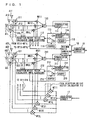
Fig. 1 is a functional block diagram functionally illustrating the
adaptive array processing performed with software by the radio base station
system in the first embodiment of the present invention. A configuration
shown in Fig. 1 is the same as that in the conventional example shown in
Fig. 6, except for the following points. Therefore, description for
components common to both examples will not be repeated.
In the configuration shown in Fig. 1, all antennas (2L: L is a positive
integer) in the radio base station system are divided into two antenna
groups (A11, A12, ... A1L) and (A21, A22, ..., A2L), each consisting of L
antennas. Here, L is the number that allows convergence of reception
directivity using a prescribed signal length of the known reference signal
(for example, aforementioned PR and UW in the PHS) contained in the
reception signal from the mobile terminal. The adaptive array processing
shown in the functional block diagram of Fig. 6 is performed for each
antenna group. The adaptive array processing for each antenna group has
been described with reference to Fig. 6, and description thereof will not be
repeated here.
Note that reception weight vector calculators 112 and 212 in the first
embodiment of Fig. 1 are for calculating a weight vector using MMSE
(Minimum Mean Square Error) algorithm such as aforementioned RLS, SMI
or the like.
In the first embodiment shown in Fig. 1, the sum of complex
multiplication of signals received at one antenna group A11, A12, ..., A1L
by the weight vector calculated by reception weight vector calculator 112 is
provided to maximum ratio combining circuit 18. In addition, the weight
information described later, calculated by reception weight vector calculator
112, is also provided to maximum ratio combining circuit 18. Unlike the
conventional radio base station system in Fig. 6, an output of a
demodulation circuit 111 is not directly supplied to the outside.
Moreover, the sum of complex multiplication of signals received at the
other antenna group A21, A22, ..., A2L by the weight vector calculated by
reception weight vector calculator 212 is provided to maximum ratio
combining circuit 18. In addition, the weight information calculated by
reception weight vector calculator 212 is also provided to maximum ratio
combining circuit 18. Unlike the conventional radio base station system in
Fig. 6, an output of a demodulation circuit 211 is not directly supplied to the
outside.
Maximum ratio combining circuit 18 performs maximum ratio
combining of the array output signals from the specific mobile terminal,
provided from adders 110 and 210 respectively, based on the weight
information provided from reception weight vector calculators 112 and 212
respectively. Moreover, maximum ratio combining circuit 18 generates a
reception signal from the aforementioned specific mobile terminal, and
provides the signal to demodulation circuit 19. Demodulation circuit 19
demodulates the provided reception signal to bit data, and supplies the data
to the outside.
In the following, an operation of maximum ratio combining circuit 18
will be described in detail.
In the radio base station system in the first embodiment of Fig. 1,
signals received by one antenna group A11, A12, ..., A1L are represented as
x11(t), ..., x1L(t), and the weights corresponding to respective antennas,
calculated in reception weight vector calculator 112, are represented as w11,
..., w1L. Then, an array output signal y1(t) corresponding to one antenna
group, output from adder 110, is expressed in the following equation.
yl(t) = w11 x11 (t) + ... + w1L x1L (t)
Here, when the reference signal is represented as d(t), a mean square
error MSE 1 calculated in reception weight vector calculator 112 is expressed
in the following equation.
MSE 1 = (d(t)-y1(t))2
Next, signals received by the other antenna group A21, A22, ..., A2L
are represented as x21(t), ..., x2L(t), and the weights corresponding to
respective antennas, calculated in reception weight vector calculator 212,
are represented as w21, ..., w2L. Then, an array output signal y2(t)
corresponding to the other antenna group, output from adder 210, is
expressed in the following equation.
y2(t) = w21 x21 (t) + ··· + w2L x2L (t)
Here, a mean square error MSE2 calculated by reception weight
vector calculator 212 is expressed in the following equation.
MSE2 = (d(t)-y2(t))2
Here, physically, each of MSE1 and MSE2 indicates a signal
component other than a desired wave, included in a corresponding array
output signal y1(t), y2(t) obtained as a result of the adaptive array
processing of the corresponding antenna group, that is, power of remaining
interfering wave and a noise signal.
The weight information provided to maximum ratio combining circuit
18 respectively from reception weight vector calculators 112 and 212 are
reciprocal of the mean square errors calculated in the respective reception
weight vector calculators, that is, 1/MSE 1, 1/MSE2.
Maximum ratio combining circuit 18 receives array output signals
y1(t), y2(t) and weight information 1/MSE1, 1/MSE2, and generates a
reception signal MRC(t) from the specific mobile terminal, based on a
maximum ratio combining equation below.
MRC(t) = y1(t)/MSE1 + y2(t)/MSE2
Here, a desired wave from the specific mobile terminal included in
the adaptive array output signal is represented as S(t), and signal
components other than that is tentatively represented as noise signals n1(t),
n2(t). Then, respective adaptive array output signals are expressed as
follows.
y1(t) = S (t) + n1(t)
y2 (t) = S (t) + n2(t)
In addition, during the reference signal period, signal component S(t)
of the desired wave is equal to reference signal d(t). Mean square error
MSE calculated in respective reception weight vector calculator is expressed
as follows.
MSE1 = |n1(t)|2
MSE2 = |n2(t)|2
When these array output signals y1(t), y2(t) and mean square errors
MSE1, MSE2 are substituted in the above maximum ratio combining
equations to find reception signal MRC(t), following equation (a) is obtained.
MRC(t)=(1/|n1(t)|2 +1/|n2(t)|2 )S(t)+n1(t)/|n1(t)|2 +n2(t)/|n2(t)|2
Next, the reason why signal to noise ratio SNR of the generated
reception signal is improved by the above maximum ratio combining
calculation with maximum ratio combining circuit 18 will be described.
For example, when a relation of MSE1=|n1(t)|2=0.1 is assumed, SNR
of array output signal y1(t) is as follows.
SNR of y1(t) = 10log(10) = 10dB
On the other hand, when a relation of MSE2=|n2(t)|2=0.2 is assumed,
SNR of array output signal y2(t) is obtained as follows.
SNR of y2(t) = 10log(5) = 7dB
As can be understood from the equation (a) for the above maximum
ratio combining calculation, in combining maximum ratio, amplitudes are
combined with regard to signal component S(t) of the desired wave, while
powers are combined with regard to noise signals n1(t), n2(t).
When these specific figures are substituted in the above equation (a),
the power of signal component S(t) will attain 15*15=225. On the other
hand, the power of the noise component is calculated in the following
manner.
(10*sqrt(0.1))2 +(5*sqrt(0.2))2 = 100*0.1+25*0.2 = 15
Therefore, SNR of signal MRC that has been subjected to maximum
ratio combining is calculated in the following manner.
10log(225/15) = 10log(15) = 11.8dB
Thus, it is understood that SNR of the signal that has been subjected
to maximum ratio combining is better, compared with the value for MSE
described above.
It is to be noted that MSE calculated in each of reception weight
vector calculators 112 and 212 may be a value averaged by a specific time T
in an appropriate frame of the reception signal. Here, MSE1 and MSE2
are expressed in the following equations
MSE1 = Σ(d(t)-y1(t))2 /T
MSE2 = Σ(d(t)-y2(t))2 /T
As described above, in the first embodiment of the present invention,
all antennas (2L) in the radio base station system are divided into the
antenna groups including antennas in the number (L) that allows
convergence of the weight vector using a reference signal length. Then, the
adaptive array processings are performed for respective antenna groups,
and the resulted array output signals are subjected to maximum ratio
combining, using the weight information reflecting accuracy of the adaptive
array processings (for example, the reciprocal of the mean square error
between the reference signal and the array output signal). Therefore,
reception directivity can converge in all antennas using the limited
reference signal length.
In addition, even if all antennas are divided into two antenna groups
in this manner, the reception signal from the specific mobile terminal can be
generated with high accuracy, by performing maximum ratio combining of
the two array outputs, taking into account the weight information of the
adaptive array processings.
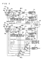
Fig. 2 is a functional block diagram functionally illustrating the
adaptive array processing performed with software by a radio base station
- system in the second embodiment of the present invention. A configuration
shown in Fig. 2 is the same as that in the first embodiment shown in Fig. 1,
except for the following points. Therefore, description for components
common to both embodiments will not be repeated.
In the configuration shown in Fig. 2, a select circuit 20 is provided
instead of maximum ratio combining circuit 18 and demodulation circuit 19
in the first embodiment of Fig. 1.
In the configuration of the first embodiment in Fig. 1, the array
output signals before demodulation to bit data, corresponding to respective
antenna groups, are combined in the maximum ratio combining circuit, and
the generated output is demodulated to bit data by demodulation circuit 19.
In the configuration of the second embodiment of Fig. 2, however, the
demodulated bit data of the array outputs corresponding to respective
antenna groups are provided to select circuit 20.
As in the first embodiment of Fig. 1, the weight information, that is,
1/MSE1, 1/MSE2, are given to select circuit 20 from reception weight vector
calculators 112 and 212 respectively.
Fig. 3 is a flowchart illustrating an operation of select circuit 20
implemented in DSP. Referring to Fig. 3, the operation of select circuit 20
in Fig. 2 will be described below.
First, the weight vectors are calculated in reception weight vector
calculators 112, 212 respectively, and array outputs y(t) and weight
information 1/MSE corresponding to respective antenna groups are output
to select circuit 20 (step S1).
Then, select circuit 20 selects an array output signal corresponding to
an antenna group having larger weight information (that is, having smaller
mean square error MSE), and outputs the signal to the outside as the
reception signal from the specific mobile terminal (step S2).
Select circuit 20 in the second embodiment does not combine the
array output signals from respective antenna groups, but selects one array
output having higher reliability out of the array outputs, based on the
weight information. Therefore, in the second embodiment, the adaptive
array processing can be simplified.
In the first and second embodiments described above, examples in
which all antennas in the radio base station system are divided into two
antenna groups have been described. The present invention, however, is
not limited to such 2-part division as described above. The present
invention can be implemented by dividing the antennas into a plurality of
antenna groups in accordance with the number of antennas, so long as
reception directivity can be converged using the reference signal length in
each antenna group.
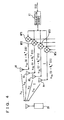
Next, Fig. 4 is a partial functional block diagram illustrating an effect
of the embodiment of the present invention, while Figs. 5A and 5B are
schematic diagrams of transmission directivity. In the following, referring
to Figs. 4, 5A and 5B, a principle will specifically be described, with which
sufficient array gain can be obtained, and transmission directivity from the
radio base station system to the mobile terminal and radio wave coverage
are improved, when an ideal weight vector can be calculated with the
present invention even if the number of antennas increases.
Fig. 4 is a functional block diagram showing a function of a
transmission system of the radio base station system which can achieve
convergence of the weight vector in all antennas (n). After modulated in
modulation circuit 17, a transmission signal S(t) is provided to one inputs of
respective multipliers MT1, MT2, ..., MTn in the transmission system. The
weight vector targeted for the specific mobile terminal, calculated in the
reception weight vector calculator, is copied and applied to these multipliers.
From respective multipliers, signals represented by the following equations
(1) to (4) are output, and provided to antennas A1, A2, ..., An.
xTX1 (t) = w1 * s(t)
xTX2 (t) = w2 * s(t)
xTX3 (t) = w3 * s(t)
xTXn (t) = wn * s(t)
A down transmission signal from the radio base station system to a
specific mobile terminal 20 is received by mobile terminal 20. When the
reception signal vector is represented as h11, h12, ..., h1n, reception signal y(t)
at mobile terminal 20 will be expressed with the following equation (5).
y(t) = h11 xTX1 (t)+···+h1n xTXn (t) = (h11 w1 * +···h1n wn * )S(t)
Here, according to the embodiment of the present invention described
above, it is assumed that the number of antennas in each antenna group
constituting the entire antennas n is not larger than half the prescribed
reference signal length, and that a reception weight vector is sufficiently
converged in the radio base station system as a whole. Then, the following
equation (6) is established, and a down antenna gain with respect to mobile
terminal 20 is maximized.
(h11 w1 * +...+ h1n wn * )=1.0
(h11 w1 * +···+h1n wn * )<1.0
A manner of convergence of transmission directivity in this example
will be described with reference to Fig. 5A. Here, an arrow in Figs. 5A and
5B indicates a direction viewing the radio base station system from the
mobile terminal, while a curve intersecting the arrow indicates directivity in
a down direction from the radio base station system to the mobile terminal.
In Fig. 5A, if the antenna gain in the down direction from the radio
base station system attains the maximum value as shown in the above
equation (6), the peak of the directivity is directed toward the mobile
terminal, and the coverage of the transmission radio wave is maximized.
In contrast, if it is assumed that the reception weight vector in the
radio base station system is not sufficiently converged, the above equation
(7) is established, and the down antenna gain with respect to mobile
terminal 20 is not maximized.
A manner of convergence of transmission directivity in this example
will be described with reference to Fig. 5B. In Fig. 5B, if the down antenna
gain from the radio base station system is not maximized as shown in the
above equation (7), the peak of the directivity is deviated from the direction
of mobile terminal, and the coverage of the transmission radio wave is not
maximized, as in Fig. 5A.
Thus, according to the configuration of the embodiment of the present
invention, antennas in the entire radio base station system are divided into
a plurality of antenna groups each including antennas in the number that
allows convergence of reception directivity using the signal length of the
known reference signal. Then, the adaptive array processing is performed
for each of the plurality of antenna groups, and the weight vector is
converged in all antennas in the radio base station system. Thus,
convergence of reception directivity can be facilitated, and the antenna gain
in transmission can be increased, without expanding the known reference
signal itself.
As described above, according to the present invention, antennas in
the entire radio base station system are divided into a plurality of antenna
groups each including antennas in the number that allows convergence of
reception directivity using the signal length of the known reference signal.
Then, the adaptive array processing is performed for each of the plurality of
antenna groups. The array output signals obtained for the plurality of
antenna groups are processed in accordance with the weight information
based on accuracy of the adaptive array processings for the plurality of
antenna groups, and the reception signal from the specific mobile terminal
is generated. Therefore, the adaptive array processing using larger
number of antennas can be achieved, without increasing the signal length of
the known reference signal itself. Thus, the antenna gain can be increased,
and the coverage of the transmission radio wave can be expanded, without
lowering data throughput.
As described above, according to the radio base station system and
the method of controlling directivity of the present invention, the adaptive
array processing using larger number of antennas with the reference signals
of the limited signal length can be achieved. Therefore, the antenna gain
can be increased without lowering data throughput, which is useful in
expanding coverage of the transmission radio wave in the radio base station
system.
Claims (12)
- A radio base station system communicating signals with a plurality of mobile terminals using a plurality of antennas (A11 to A1L, A21 to A2L), said signal being divided into signal sections including a known reference signal of a first signal length and a data signal of a second signal length, said plurality of antennas being divided into a plurality of antenna groups each including antennas in a number that allows convergence of reception directivity using the known reference signal of said first signal length, the radio base station system comprising:a plurality of adaptive array processing portions (MR11 to MR1L, 110 to 116, MR21 to MR2L, 210 to 216) provided corresponding to said plurality of antenna groups respectively, each performing a prescribed adaptive array processing to signals received at corresponding said antenna group to extract an array output signal corresponding to a specific mobile terminal among said plurality of mobile terminals, and generating weight information based on accuracy of said adaptive array processing; anda reception signal generating portion (18, 20) generating a reception signal from said specific mobile terminal, based on a plurality of said array output signals corresponding to said specific mobile terminal and a plurality of pieces of said weight information supplied from said plurality of adaptive array processing portions.
- The radio base station system according to claim 1, wherein
said reception signal generating portion includes a maximum ratio combining portion (18) generating the reception signal from said specific mobile terminal by performing maximum ratio combining of the plurality of said array output signals corresponding to said specific mobile terminal and the plurality of pieces of said weight information. - The radio base station system according to claim 1, wherein
said reception signal generating portion includes a select portion (20) comparing the plurality of pieces of said weight information, selecting any one of the plurality of said array output signals based on that result, and outputting the signal as the reception signal from said specific mobile terminal. - The radio base station system according to claim 1, wherein
said weight information is based on a mean square error between said array output calculated by each of said adaptive array processing portions and said reference signal. - The radio base station system according to claim 1, further comprising a directivity convergence portion (MT11 to MT1L, MT21 to MT2L) converging transmission directivity of a transmission signal to said specific mobile terminal, based on results of adaptive array processings by said plurality of adaptive array processing portions.
- The radio base station system according to claim 1, wherein
a number of antennas that allows convergence of reception directivity is not larger than half said first signal length of said reference signal. - A method of controlling directivity in a radio base station system communicating signals with a plurality of mobile terminals using a plurality of antennas (A11 to A1L, A21 to A2L), said signal being divided into signal sections including a known reference signal of a first signal length and a data signal of a second signal length, said method comprising the steps of:dividing said plurality of antennas into a plurality of antenna groups each including antennas in a number that allows convergence of reception directivity using the known reference signal of said first signal length;performing a prescribed adaptive array processing to signals received at corresponding said antenna group for each of said plurality of antenna groups to extract an array output signal corresponding to a specific mobile terminal among said plurality of mobile terminals, and generating weight information based on accuracy of said adaptive array processing; andgenerating a reception signal from said specific mobile terminal, based on a plurality of said array output signals corresponding to said specific mobile terminal and a plurality of pieces of said weight information.
- The method according to claim 7, wherein
said step of generating said reception signal includes the step of generating the reception signal from said specific mobile terminal by performing maximum ratio combining of the plurality of said array output signals corresponding to said specific mobile terminal and the plurality of pieces of said weight information. - The method according to claim 7, wherein
said step of generating said reception signal includes the step of comparing the plurality of pieces of said weight information, selecting any one of the plurality of said array output signals based on that result, and outputting the signal as the reception signal from said specific mobile terminal. - The method according to claim 7, wherein
said weight information is based on a mean square error between said array output calculated through said prescribed adaptive array processing and said reference signal. - The method according to claim 7, further comprising the step of converging transmission directivity of a transmission signal to said specific mobile terminal, based on results of said adaptive array processings.
- The method according to claim 7, wherein
a number of antennas that allows convergence of reception directivity is not larger than half said first signal length of said reference signal.
Applications Claiming Priority (3)
| Application Number | Priority Date | Filing Date | Title |
|---|---|---|---|
| JP2001080423A JP3973371B2 (en) | 2001-03-21 | 2001-03-21 | Radio base system and directivity control method |
| JP2001080423 | 2001-03-21 | ||
| PCT/JP2001/006991 WO2002075957A1 (en) | 2001-03-21 | 2001-08-13 | Wireless base system, and directivity control method |
Publications (2)
| Publication Number | Publication Date |
|---|---|
| EP1381174A1 true EP1381174A1 (en) | 2004-01-14 |
| EP1381174A4 EP1381174A4 (en) | 2010-01-13 |
Family
ID=18936715
Family Applications (1)
| Application Number | Title | Priority Date | Filing Date |
|---|---|---|---|
| EP01956868A Withdrawn EP1381174A4 (en) | 2001-03-21 | 2001-08-13 | WIRELESS BASE SYSTEM, AND DIRECTIVITY CONTROL METHOD |
Country Status (5)
| Country | Link |
|---|---|
| US (1) | US7403798B2 (en) |
| EP (1) | EP1381174A4 (en) |
| JP (1) | JP3973371B2 (en) |
| CN (1) | CN100508425C (en) |
| WO (1) | WO2002075957A1 (en) |
Families Citing this family (22)
| Publication number | Priority date | Publication date | Assignee | Title |
|---|---|---|---|---|
| JP3679075B2 (en) * | 2002-09-13 | 2005-08-03 | 松下電器産業株式会社 | Radio transmission apparatus and radio transmission method |
| GB2416095B (en) * | 2003-05-02 | 2006-09-20 | Fujitsu Ltd | Multi-antenna system and antenna unit |
| US8483105B2 (en) | 2003-10-15 | 2013-07-09 | Qualcomm Incorporated | High speed media access control |
| US8472473B2 (en) * | 2003-10-15 | 2013-06-25 | Qualcomm Incorporated | Wireless LAN protocol stack |
| US8462817B2 (en) | 2003-10-15 | 2013-06-11 | Qualcomm Incorporated | Method, apparatus, and system for multiplexing protocol data units |
| US9226308B2 (en) | 2003-10-15 | 2015-12-29 | Qualcomm Incorporated | Method, apparatus, and system for medium access control |
| US8233462B2 (en) | 2003-10-15 | 2012-07-31 | Qualcomm Incorporated | High speed media access control and direct link protocol |
| US7664533B2 (en) * | 2003-11-10 | 2010-02-16 | Telefonaktiebolaget Lm Ericsson (Publ) | Method and apparatus for a multi-beam antenna system |
| US8903440B2 (en) | 2004-01-29 | 2014-12-02 | Qualcomm Incorporated | Distributed hierarchical scheduling in an ad hoc network |
| US7564814B2 (en) * | 2004-05-07 | 2009-07-21 | Qualcomm, Incorporated | Transmission mode and rate selection for a wireless communication system |
| JP4728597B2 (en) * | 2004-06-09 | 2011-07-20 | 日本無線株式会社 | Array antenna communication device |
| JP4555651B2 (en) * | 2004-09-29 | 2010-10-06 | 京セラ株式会社 | COMMUNICATION METHOD AND RADIO DEVICE USING THE SAME |
| US20060240784A1 (en) * | 2005-04-22 | 2006-10-26 | Qualcomm Incorporated | Antenna array calibration for wireless communication systems |
| JP4905874B2 (en) * | 2005-04-27 | 2012-03-28 | 京セラ株式会社 | Radio communication apparatus and control method in radio communication apparatus |
| US8498669B2 (en) * | 2005-06-16 | 2013-07-30 | Qualcomm Incorporated | Antenna array calibration for wireless communication systems |
| US8600336B2 (en) | 2005-09-12 | 2013-12-03 | Qualcomm Incorporated | Scheduling with reverse direction grant in wireless communication systems |
| US8576846B2 (en) | 2005-10-05 | 2013-11-05 | Qualcomm Incorporated | Peer-to-peer communication in ad hoc wireless network |
| US9118111B2 (en) * | 2005-11-02 | 2015-08-25 | Qualcomm Incorporated | Antenna array calibration for wireless communication systems |
| US8280430B2 (en) * | 2005-11-02 | 2012-10-02 | Qualcomm Incorporated | Antenna array calibration for multi-input multi-output wireless communication systems |
| US8199708B2 (en) * | 2008-12-30 | 2012-06-12 | Telefonaktiebolaget L M Ericsson (Publ) | Allocation of uplink reference signals in a mobile communication system |
| WO2014035216A1 (en) * | 2012-08-31 | 2014-03-06 | 엘지전자 주식회사 | Method and apparatus for virtualizing antenna in wireless communication system |
| WO2020072487A1 (en) * | 2018-10-01 | 2020-04-09 | Fortem Technologies, Inc. | System and method for radar disambiguation techniques |
Family Cites Families (12)
| Publication number | Priority date | Publication date | Assignee | Title |
|---|---|---|---|---|
| JP2561031B2 (en) * | 1994-06-07 | 1996-12-04 | 日本電気株式会社 | Transceiver |
| US6173014B1 (en) * | 1994-08-02 | 2001-01-09 | Telefonaktiebolaget Lm Ericsson | Method of and apparatus for interference rejection combining and downlink beamforming in a cellular radio communications system |
| JP3526196B2 (en) * | 1997-01-07 | 2004-05-10 | 株式会社東芝 | Adaptive antenna |
| JP3391662B2 (en) * | 1997-06-06 | 2003-03-31 | 松下電器産業株式会社 | Adaptive array antenna receiver |
| BR9812816A (en) * | 1997-09-15 | 2000-08-08 | Adaptive Telecom Inc | Processes for wireless communication, and to efficiently determine a space channel of the mobile unit in a wireless communication system at the base station, and cdma base station |
| EP0936755B1 (en) * | 1998-02-13 | 2005-07-06 | Nec Corporation | Adaptive receiving device with antenna array |
| JP3465739B2 (en) * | 1998-04-07 | 2003-11-10 | 日本電気株式会社 | CDMA adaptive antenna receiving apparatus and communication system |
| CN100413147C (en) * | 1998-07-13 | 2008-08-20 | Ntt移动通信网株式会社 | adaptive array antenna |
| JP2000082982A (en) | 1998-09-03 | 2000-03-21 | Nec Corp | Array antenna receiver |
| JP3326416B2 (en) | 1998-10-30 | 2002-09-24 | 三洋電機株式会社 | Adaptive array device |
| JP3341701B2 (en) | 1999-03-05 | 2002-11-05 | 日本電気株式会社 | Array antenna transmitter |
| JP3872953B2 (en) * | 1999-12-27 | 2007-01-24 | 株式会社東芝 | Wireless communication device using adaptive antenna |
-
2001
- 2001-03-21 JP JP2001080423A patent/JP3973371B2/en not_active Expired - Fee Related
- 2001-08-13 CN CNB018230660A patent/CN100508425C/en not_active Expired - Fee Related
- 2001-08-13 US US10/471,280 patent/US7403798B2/en not_active Expired - Fee Related
- 2001-08-13 EP EP01956868A patent/EP1381174A4/en not_active Withdrawn
- 2001-08-13 WO PCT/JP2001/006991 patent/WO2002075957A1/en not_active Ceased
Also Published As
| Publication number | Publication date |
|---|---|
| US7403798B2 (en) | 2008-07-22 |
| JP3973371B2 (en) | 2007-09-12 |
| EP1381174A4 (en) | 2010-01-13 |
| US20040110538A1 (en) | 2004-06-10 |
| WO2002075957A1 (en) | 2002-09-26 |
| CN100508425C (en) | 2009-07-01 |
| CN1494773A (en) | 2004-05-05 |
| JP2002280953A (en) | 2002-09-27 |
Similar Documents
| Publication | Publication Date | Title |
|---|---|---|
| US7403798B2 (en) | Wireless base system, and directivity control method | |
| JP4131702B2 (en) | Reduce interference using a simple antenna array | |
| JP3526196B2 (en) | Adaptive antenna | |
| AU739043B2 (en) | Selective diversity combining | |
| KR100445490B1 (en) | Radio base station device and radio communication method | |
| US6836244B2 (en) | Radio reception apparatus capable of selecting from adaptive array reception mode and single route reception mode, and method and program for controlling adaptive array processing | |
| US7149547B2 (en) | Diversity transmission | |
| JP4202162B2 (en) | Adaptive array radio apparatus, antenna selection method, and antenna selection program | |
| WO2005020467A1 (en) | Apparatus and method for receiving signal in mobile communication system using adaptive antenna array scheme | |
| CN1533065A (en) | Smart antenna uplink beamforming method and device | |
| EP1583258B1 (en) | Array antenna radio communication apparatuses | |
| JP3746983B2 (en) | Mobile communication terminal and array antenna directivity control method thereof | |
| JP3579363B2 (en) | Wireless receiving apparatus and wireless receiving method | |
| US7398098B2 (en) | Radio base apparatus, transmission power control method, and transmission power control program | |
| CN1145384C (en) | Array transmitting method and equipment for broad-band radio communication system | |
| WO2004084576A2 (en) | Symbol estimation-based decorrelator for estimating spatial signatures in a wireless communications system | |
| US6449468B1 (en) | Mobile radiocommunication terminal comprising at least two antennas with a diversity of polarizations for signal reception | |
| KR20020057594A (en) | Apparatus for smart antenna using phase estimation | |
| KR100270474B1 (en) | Baseband signal processing blocks in adaptive array antenna system | |
| JP4592662B2 (en) | Radio base apparatus, transmission power control method, and transmission power control program | |
| KR100278543B1 (en) | Smart Antenna System Using Parallel Searcher | |
| JP2003060568A (en) | Radio base station, transmission power control method, and transmission power control program | |
| Ghanem et al. | Performance enhancement of CDMA cellular systems with a new adaptive algorithm for base station antenna arrays | |
| JP2005244853A (en) | Adaptive array antenna system, adaptive array antenna control method, and wireless device | |
| JP2003078472A (en) | Radio base station, transmission directivity control method, and transmission directivity control program |
Legal Events
| Date | Code | Title | Description |
|---|---|---|---|
| PUAI | Public reference made under article 153(3) epc to a published international application that has entered the european phase |
Free format text: ORIGINAL CODE: 0009012 |
|
| 17P | Request for examination filed |
Effective date: 20031010 |
|
| AK | Designated contracting states |
Kind code of ref document: A1 Designated state(s): AT BE CH CY DE DK ES FI FR GB GR IE IT LI LU MC NL PT SE TR |
|
| AX | Request for extension of the european patent |
Extension state: AL LT LV MK RO SI |
|
| A4 | Supplementary search report drawn up and despatched |
Effective date: 20091216 |
|
| STAA | Information on the status of an ep patent application or granted ep patent |
Free format text: STATUS: THE APPLICATION HAS BEEN WITHDRAWN |
|
| 18W | Application withdrawn |
Effective date: 20100316 |