EP1381096A2 - White organic light-emitting devices using rubrene layer - Google Patents
White organic light-emitting devices using rubrene layer Download PDFInfo
- Publication number
- EP1381096A2 EP1381096A2 EP03076997A EP03076997A EP1381096A2 EP 1381096 A2 EP1381096 A2 EP 1381096A2 EP 03076997 A EP03076997 A EP 03076997A EP 03076997 A EP03076997 A EP 03076997A EP 1381096 A2 EP1381096 A2 EP 1381096A2
- Authority
- EP
- European Patent Office
- Prior art keywords
- light
- layer
- emitting layer
- emitting
- transport layer
- Prior art date
- Legal status (The legal status is an assumption and is not a legal conclusion. Google has not performed a legal analysis and makes no representation as to the accuracy of the status listed.)
- Granted
Links
- 0 *c(cc1)cc(cc2)c1cc2-c1c(cccc2)c2c(-c(cc2)cc(cc3)c2cc3ON)c2ccccc12 Chemical compound *c(cc1)cc(cc2)c1cc2-c1c(cccc2)c2c(-c(cc2)cc(cc3)c2cc3ON)c2ccccc12 0.000 description 1
Images


Classifications
-
- H—ELECTRICITY
- H10—SEMICONDUCTOR DEVICES; ELECTRIC SOLID-STATE DEVICES NOT OTHERWISE PROVIDED FOR
- H10K—ORGANIC ELECTRIC SOLID-STATE DEVICES
- H10K85/00—Organic materials used in the body or electrodes of devices covered by this subclass
- H10K85/60—Organic compounds having low molecular weight
- H10K85/615—Polycyclic condensed aromatic hydrocarbons, e.g. anthracene
- H10K85/626—Polycyclic condensed aromatic hydrocarbons, e.g. anthracene containing more than one polycyclic condensed aromatic rings, e.g. bis-anthracene
-
- H—ELECTRICITY
- H05—ELECTRIC TECHNIQUES NOT OTHERWISE PROVIDED FOR
- H05B—ELECTRIC HEATING; ELECTRIC LIGHT SOURCES NOT OTHERWISE PROVIDED FOR; CIRCUIT ARRANGEMENTS FOR ELECTRIC LIGHT SOURCES, IN GENERAL
- H05B33/00—Electroluminescent light sources
- H05B33/12—Light sources with substantially two-dimensional [2D] radiating surfaces
- H05B33/14—Light sources with substantially two-dimensional [2D] radiating surfaces characterised by the chemical or physical composition or the arrangement of the electroluminescent material, or by the simultaneous addition of the electroluminescent material in or onto the light source
-
- H—ELECTRICITY
- H10—SEMICONDUCTOR DEVICES; ELECTRIC SOLID-STATE DEVICES NOT OTHERWISE PROVIDED FOR
- H10K—ORGANIC ELECTRIC SOLID-STATE DEVICES
- H10K50/00—Organic light-emitting devices
- H10K50/10—OLEDs or polymer light-emitting diodes [PLED]
- H10K50/11—OLEDs or polymer light-emitting diodes [PLED] characterised by the electroluminescent [EL] layers
- H10K50/125—OLEDs or polymer light-emitting diodes [PLED] characterised by the electroluminescent [EL] layers specially adapted for multicolour light emission, e.g. for emitting white light
-
- H—ELECTRICITY
- H10—SEMICONDUCTOR DEVICES; ELECTRIC SOLID-STATE DEVICES NOT OTHERWISE PROVIDED FOR
- H10K—ORGANIC ELECTRIC SOLID-STATE DEVICES
- H10K2102/00—Constructional details relating to the organic devices covered by this subclass
- H10K2102/301—Details of OLEDs
- H10K2102/351—Thickness
-
- H—ELECTRICITY
- H10—SEMICONDUCTOR DEVICES; ELECTRIC SOLID-STATE DEVICES NOT OTHERWISE PROVIDED FOR
- H10K—ORGANIC ELECTRIC SOLID-STATE DEVICES
- H10K50/00—Organic light-emitting devices
- H10K50/10—OLEDs or polymer light-emitting diodes [PLED]
- H10K50/11—OLEDs or polymer light-emitting diodes [PLED] characterised by the electroluminescent [EL] layers
-
- H—ELECTRICITY
- H10—SEMICONDUCTOR DEVICES; ELECTRIC SOLID-STATE DEVICES NOT OTHERWISE PROVIDED FOR
- H10K—ORGANIC ELECTRIC SOLID-STATE DEVICES
- H10K50/00—Organic light-emitting devices
- H10K50/10—OLEDs or polymer light-emitting diodes [PLED]
- H10K50/14—Carrier transporting layers
-
- H—ELECTRICITY
- H10—SEMICONDUCTOR DEVICES; ELECTRIC SOLID-STATE DEVICES NOT OTHERWISE PROVIDED FOR
- H10K—ORGANIC ELECTRIC SOLID-STATE DEVICES
- H10K85/00—Organic materials used in the body or electrodes of devices covered by this subclass
- H10K85/60—Organic compounds having low molecular weight
- H10K85/631—Amine compounds having at least two aryl rest on at least one amine-nitrogen atom, e.g. triphenylamine
-
- Y—GENERAL TAGGING OF NEW TECHNOLOGICAL DEVELOPMENTS; GENERAL TAGGING OF CROSS-SECTIONAL TECHNOLOGIES SPANNING OVER SEVERAL SECTIONS OF THE IPC; TECHNICAL SUBJECTS COVERED BY FORMER USPC CROSS-REFERENCE ART COLLECTIONS [XRACs] AND DIGESTS
- Y10—TECHNICAL SUBJECTS COVERED BY FORMER USPC
- Y10S—TECHNICAL SUBJECTS COVERED BY FORMER USPC CROSS-REFERENCE ART COLLECTIONS [XRACs] AND DIGESTS
- Y10S428/00—Stock material or miscellaneous articles
- Y10S428/917—Electroluminescent
-
- Y—GENERAL TAGGING OF NEW TECHNOLOGICAL DEVELOPMENTS; GENERAL TAGGING OF CROSS-SECTIONAL TECHNOLOGIES SPANNING OVER SEVERAL SECTIONS OF THE IPC; TECHNICAL SUBJECTS COVERED BY FORMER USPC CROSS-REFERENCE ART COLLECTIONS [XRACs] AND DIGESTS
- Y10—TECHNICAL SUBJECTS COVERED BY FORMER USPC
- Y10T—TECHNICAL SUBJECTS COVERED BY FORMER US CLASSIFICATION
- Y10T428/00—Stock material or miscellaneous articles
- Y10T428/26—Web or sheet containing structurally defined element or component, the element or component having a specified physical dimension
Definitions
- the present invention relates to OLED devices that emit white light.
- An OLED device includes a substrate, an anode, a hole-transport layer made of an organic compound, an organic luminescent layer with suitable dopants, an organic electron-transport layer, and a cathode.
- OLED devices are attractive because of their low driving voltage, high luminance, wide-angle viewing and capability for full-color flat emission displays. Tang and others described this multilayer OLED device in their US-A-4,769,292 and US-A-4,885,211.
- Efficient white light producing OLED devices are considered a low cost alternative for several applications such as paper-thin light sources backlights in LCD displays, automotive dome lights, and office lighting.
- White light producing OLED devices should be bright, efficient, and generally have Commission International d'Eclairage (CIE) chromaticity coordinates of about (0.33, 0.33).
- CIE Commission International d'Eclairage
- white light is that light which is perceived by a user as having a white color.
- the luminescent layer includes a red and blue light-emitting material uniformly dispersed in a host emitting material.
- This device has good electroluminescent characteristics, but the concentration of the red and blue dopants are very small, such as 0.12% and 0.25% of the host material. These concentrations are difficult to control during large-scale manufacturing.
- JP 07,142,169 discloses an OLED device, capable of emitting white light, made by sticking a blue light-emitting layer next to the hole-transport layer and followed by a green light-emitting layer having a region containing a red fluorescent layer.
- this device three emitter layers with different carrier transporting properties, each emitting blue, green, or red light, are used to generate white light.
- Littman and others in US-A-5,405,709 disclose another white emitting device, which is capable of emitting white light in response to hole-electron recombination and comprises a fluorescent in a visible light range from bluish green to red.
- white light producing OLED devices with high luminance efficiency and operational stability can be obtained by depositing yellow light-emitting layer adjacent to the blue emission layer.
- an organic light-emitting diode (OLED) device which produces substantially white light, comprising:
- an organic light-emitting diode device which produces substantially white light, comprising:
- OLED devices made in accordance with the present invention can be produced with high reproducibility and consistently provide high light efficiency. These devices have high operational stability and also require low drive voltage.
- a conventional light-emitting layer of the organic OLED device comprises a luminescent or fluorescent material where electroluminescence is produced as a result of electron-hole pair recombination in this region.
- a light-emitting layer 140 is sandwiched between anode 120 and cathode 150.
- the substrate is labeled as 110.
- the light-emitting layer 140 is a pure material with a high luminescent efficiency.
- a well known material is tris(8-quinolinato) aluminum (Alq) which produces excellent green electroluminescence.
- the simple structure can be modified to a three-layer structure as shown in FIG. 2, in which an additional electroluminescent layer is introduced between the hole and electron-transport layers to function primarily as the site for hole-electron recombination and thus electroluminescence.
- the functions of the individual organic layers are distinct and can therefore be optimized independently.
- the electroluminescent or recombination layer can be chosen to have a desirable OLED color as well as high luminance efficiency.
- the electron and hole-transport layers can be optimized primarily for the carrier transport property. It will be understood to those skilled in the art that the electron-transport layer and the cathode can be made to be transparent thus facilitating illumination of the device through its top layer and not through the substrate.
- an organic light-emitting device 200 has a light-transmissive substrate 210 on which is disposed a light-transmissive anode 220.
- An organic light-emitting structure is formed between the anode 220 and a cathode 270.
- the organic light-emitting structure is comprised of, in sequence, a hole injection (thin fluorocarbon) layer 230, an organic hole-transport layer 240, an organic light-emitting layer 250, and an organic electron-transport layer 260.
- the cathode When an electrical potential difference (not shown) is applied between the anode 220 and the cathode 270, the cathode will inject electrons into the electron-transport layer 260, and the electrons will migrate across layer 240 to the light-emitting layer 250. At the same time, holes will be injected from the anode 220 into the hole-transport layer 240. The holes will migrate across layer 230 and recombine with electrons at or near a junction formed between the hole-transport layer 240 and the light-emitting layer 250. When a migrating electron drops from its conduction band to a valance band in filling a hole, energy is released as light, which is emitted through the light-transmissive anode 220 and substrate 210.
- the organic OLED devices can be viewed as a diode, which is forward biased when the anode is at a higher potential than the cathode.
- the anode and cathode of the organic OLED device can each take any convenient conventional form, such as any of the various forms disclosed by Tang and others US-A-4,885,211. Operating voltage can be substantially reduced when using a low-work function cathode and a high-work function anode.
- the preferred cathodes are those constructed of a combination of a metal having a work function less than 4.0 eV and one other metal, preferably a metal having a work function greater than 4.0 eV.
- the Mg:Ag of Tang and others US-A-4,885,211 constitutes one preferred cathode construction.
- the Al:Mg cathodes of Van Slyke and others' US-A-5,059,862 is another preferred cathode construction. Hung and others in US-A-5,776,622 has disclosed the use of a LiF/Al bilayer to enhance electron injection in organic OLED devices. Cathodes made of either Mg:Ag, Al:Mg, or LiF/Al are opaque and displays cannot be viewed through the cathode. Recently, series of publications (Gu and others in APL 68, 2606 [1996]; Burrows and others, J. Appl. Phys.
- Conventional anodes 220 are formed of a conductive and transparent oxide. Indium tin oxide has been widely used as the anode contact because of its transparency, good conductivity, and high work function.
- an anode 220 can be modified with a hole injection layer 220b.
- a hole injection layer 220b An example of material in such a hole injection layer are the fluorocarbons disclosed by Hung and others US-A-6,208,075.
- the light-transmissive substrate 210 can be constructed of glass, quartz, or a plastic material.
- Preferred materials for use in forming the hole-transport layer of the organic OLED devices are tertiary amines as taught in Van Slyke US-A-4,539,507.
- Another class of preferred amines is tetraaryl amines.
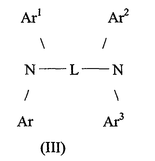
- Preferred tetraaryldiamines include two diarylamino groups, such as indicated by formula (III), linked through an arylene group.
- Preferred tetraaryldiamines include those represented by formula: wherein:
- the various alkyl, alkylene, aryl, and arylene moieties of the can each in turn be substituted for structural formulae of tertiary amines.
- Typical substituents include alkyl groups, alkoxy groups, aryl groups, aryloxy groups, and halogen such as fluoride, chloride, and bromide.
- the various alkyl and alkylene moieties typically contain from about 1 to 6 carbon atoms.
- the cycloalkyl moieties can contain from 3 to about 10 carbon atoms, but typically contain 5, 6, or 7 ring carbon atoms, for example, cyclopentyl, cyclohexyl, and cycloheptyl ring structures.
- the aryl and arylene moieties are not fused aromatic ring moieties, they are preferably phenyl and phenylene moieties.
- ATA aromatic tertiary amines
- Preferred materials for use in forming the electron-transport layer of the organic OLED devices of this invention are metal chelated oxinoid compounds, including chelates of oxine itself (also commonly referred to as 8-quinolinol or 8-hydroxyquinoline) as disclosed in US-A-4,885,211. Such compounds exhibit both high levels of performance and are readily fabricated in the form of thin layers.
- the electron-transport layer also can be made of porphyrinic compound as disclosed in US-A-5,683,823. Highly preferred examples of useful porphyrinic compounds are metal free phthalocyanines and metal containing phthalocyanines. Illustrative of useful porphyrinic compound is copper phthalocyanine (CuPc).
- a preferred embodiment of the luminescent layer consists of a host material doped with fluorescent dyes. Using this method, highly efficient EL devices can be constructed. Simultaneously, the color of the EL devices can be tuned by using fluorescent dyes of different emission wavelengths in a common host material. Tang and others in commonly assigned US-A-4,769,292 has described this dopant scheme in considerable detail for EL devices using Alq as the host material.
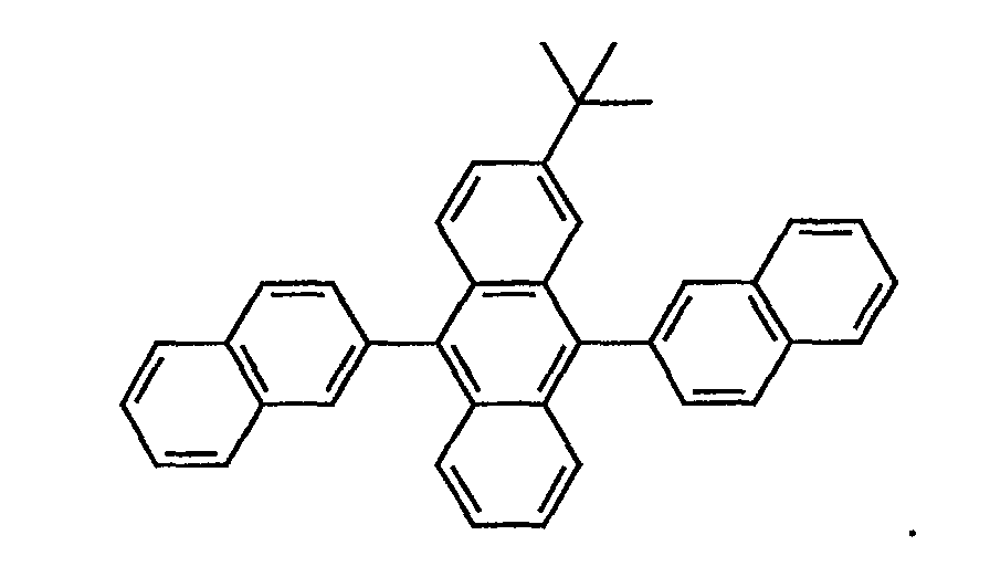
- Preferred host materials for the blue luminescent layer of this invention include:
- Preferred materials for use as a yellow emission layer are rubrene class materials. These are hydrocarbon compounds containing a polycyclic benzoid chromophoric unit. Hamada and others reported in Applied Phys. Lett. Vol. 75, 1682 (1999) a red color emitting OLED device by doping rubrene in hole-transport layers and DCM2 dopants into Alq emission layer.
- the yellow emitting layer of this invention substantially consists of herein termed rubrene or derivatives thereof, including 5,6,11,12-tetra-substituted naphthacenes having the following formula R, R', R", and R'", which may be the same or different, are individually aryl groups such as phenyl, biphenylyl, or naphthyl; or heteroaryl groups such as benzothiazolylphenyl.
- rubrene derivatives include 5,6,11,12-tetraphenylnaphthacene and 5,6,11,12-tetrakis(2-naphthyl)naphthacene.
- Additional substituents such as alkyl, aryl, fluorinated alkyl, fluoro, or cyano may be present on the naphthacene moiety, on the aryl or heteroaryl groups R, R,' R", and R"', or on both the naphthacene moiety and the aryl or hetetroaryl groups R, R', R", and R"'.
- An example of such an additionally substituted stabilizing dopant is 6,11 -diphenyl-5,12-bis(4-(6-methyl-benzothiazol-2-yl)phenyl)naphthacene.
- rubrene and rubrene derivatives with molecular weights not exceeding about 800 Daltons. Currently most preferred is rubrene.
- the term "percentage” indicates the volume percentage of a particular dopant with respect to the host material. This was based on the ratio of the thickness of each of the material recorded on the thickness monitor during the vacuum deposition process.
- FIGS. 3-5 show the white light producing OLED device structure prepared according to the present invention and graphs of various parameters of their operations. The invention and its advantages are further illustrated by the following specific examples.
- an organic white light-emitting device 300 has a light-transmissive substrate 310 on which is disposed a light-transmissive anode 320, hole injection layer 330, and hole-transport layer 340.
- An organic white light-emitting structure is formed between the anode 320 and a cathode 370.
- the organic light-emitting structure comprises, in sequence, an organic hole-transport layer 340, a yellow light-emitting rubrene compound layer 341 and blue-emitting layer organic light-emitting layer 350.
- An organic electron-transport layer 360 is made of Alq.
- FIG. 4 depicts an organic white light-emitting device 400 which is similar to that shown in FIG. 4, except that the yellow light-emitting layer (461) is deposited on the blue-emitting organic layer 450.
- Other layers are substrate 410, anode 420, hole injection layer 430, hole-transport layer 440, electron-transport layer 460 and cathode 470.
- FIG. 5 depicts yet another structure of organic white light-emitting OLED device 500.
- This structure contains the features of both the structures of FIG. 3 and FIG. 4.
- Layer 550 is an organic blue-emitting layer. It has two yellow emitting layers made of rubrene compound layer. The first yellow light-emitting rubrene compound layer 441 and the second yellow light-emitting rubrene compound layer 561 are disposed adjacent to the blue-emitting layer 550.
- Other layers are a substrate 510, anode 520, hole injection layer 530, hole-transport layer 540, electron-transport 560, and a cathode layer 570.
- FIG. 6 depicts yet another structure of organic white light-emitting OLED device 600. This structure is similar to that of FIG. 5, except that an additional green emitting layer 562 is deposited on the second yellow rubrene compound emitting layer.
- An OLED device was constructed in the following manner.
- Substrates coated with 80 nm ITO was sequentially ultrasonicated in a commercial detergent, rinsed in deionized water, and degreased in toluene vapor. These substrates were treated with an oxygen plasma for about one minute and coated with 1 nm fluorocarbon layer by plasma assisted deposition of CHF 3 . The same procedure was used for preparing all other devices described in this invention. These substrates were loaded into a deposition chamber for organic layers and cathode depositions.
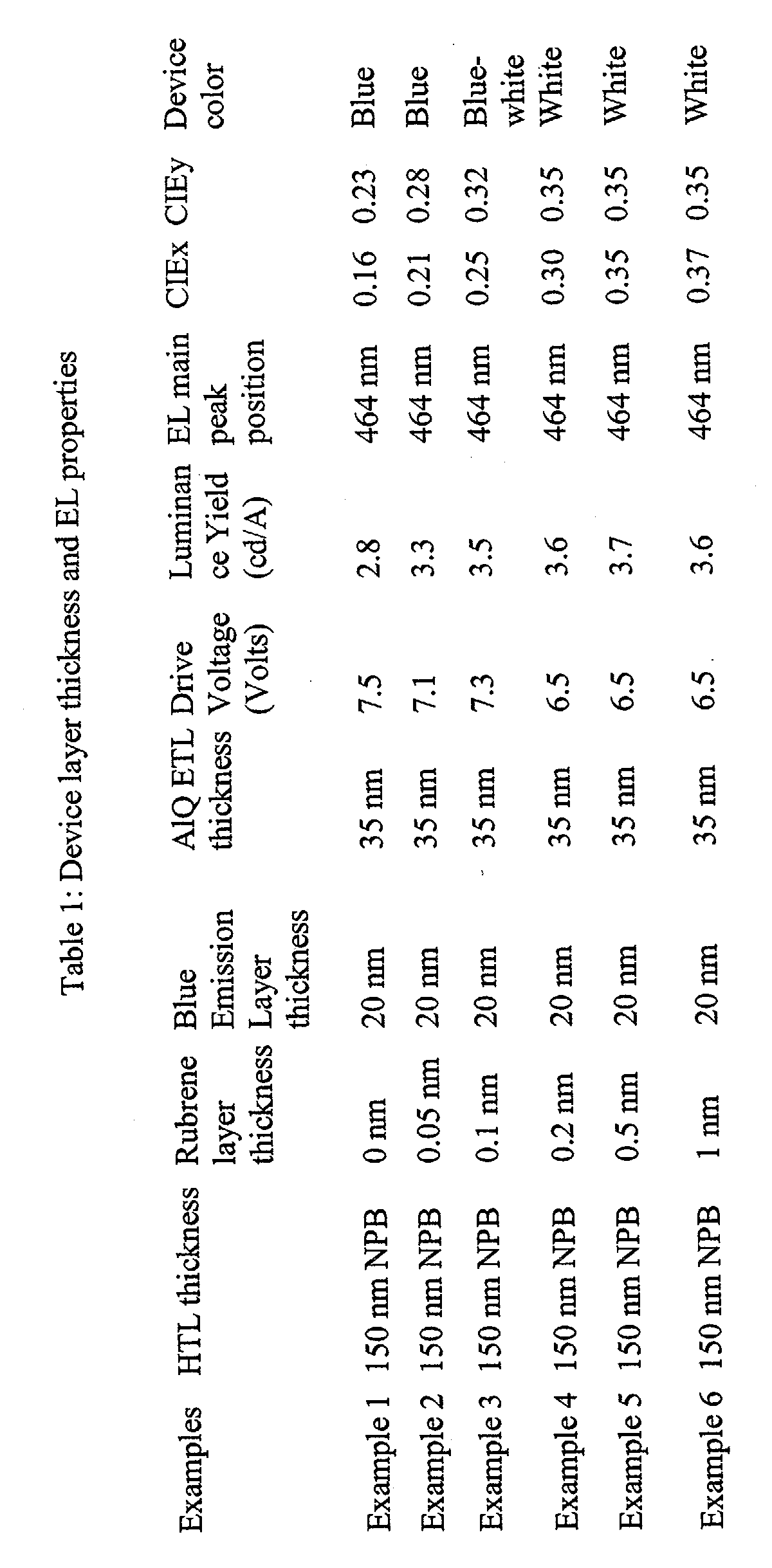
- the device of Example 1 was prepared by sequential deposition of 150 nm NPB hole-transport layer (HTL), 20 nm blue emission layer (EML) comprising TBADN host with 1.5% TBP blue dopant, 37.5 nm Alq electron-transport layer (ETL), then 0.5 nm LiF and 200 nm Al as a part of cathode.
- HTL NPB hole-transport layer
- EML blue emission layer
- ETL Alq electron-transport layer
- the OLED device was then hermetically packaged in a dry glove box filled with nitrogen for protection against ambient environment.
- Example 5 was prepared following the same sequence as the device of Example 2, except that after depositing 150 nm NPB hole-transport layer, a thin layers of rubrene compound 0.5 nm thick was deposited on the hole-transport layer. This device also has white emission.
- the device of Example 6 was prepared following the same sequence as the device of Example 2, except that after depositing 150 nm NPB hole-transport layer, a thin layers of rubrene compound 1 nm thick was deposited on the hole-transport layer. This device also has white emission.
- FIG. 7 shows the EL spectra from the device of Example 1 and from the device of Example 5.
- White color with CIE coordinates (0.35, 0.35) is obtained with luminance efficiency of 3.7 cd/A @20 mA/cm 2 , when the yellow light-emitting layer thickness is 0.1 nm to 1 nm.
- the yellow rubrene layer can be mixed with another material such as a hole-transport material such as NPB or an electron-transport material such as Alq.
- a hole-transport material such as NPB
- an electron-transport material such as Alq.
- the yellow light-emitting layer 341 of FIG. 3 or layer 541 of FIGS. 5 and 6 can be doped with NPB hole-transport material such that the yellow light-emitting layer having rubrene or a derivative thereof contains greater than 50% by volume of the rubrene constituents.
- the yellow rubrene layer can be mixed with another electron-transport material such as a Alq.
- the yellow emitting layer 461 of FIG. 4 or layer 561 of FIGS. 5 and 6 can be doped with Alq electron-transport material such that the yellow light-emitting layer having rubrene or a derivative thereof contains greater than 50% by volume of the rubrene constituents.
- the operational stability of the encapsulated OLED devices in ambient environments was found by measuring the changes in the drive voltage and the luminance as a function of time when OLED devices were operated at a constant current density of 20 mA/cm 2 .
- White OLED devices prepared by following the different structures of this invention have high operational stability.
- the white OLED devices of this invention were prepared by depositing yellow light-emitting layer adjacent to the blue-emitting layer.
- the yellow light-emitting layer was deposited over the hole-transport layer or over the blue-emitting layer, or both, on the hole-transport layer and the blue-emitting layer.
- These OLED devices have higher luminance yield and lower drive voltage. These OLED devices can be operated at higher current density with minimum degradation in the color coordinates and the luminance efficiency
- the OLED device wherein the blue light-emitting layer includes the blue dopant selected from the group consisting of:
- the OLED device wherein the thickness of the rubrene compound is between 0.1 to 5 nm and the volume percent of the rubrene compound is greater than 50% by volume of the constituents of the yellow light-emitting layer.
- the OLED device wherein thickness of the blue light emission layer is between 10 nm - 100 nm.
- the OLED device wherein thickness of the electron-transport layer is between 10 nm - 150 nm.
- the OLED device wherein the cathode is selected from the group of LiF/Al, Mg:Ag alloy, and Al-Li alloy.
- the OLED device wherein the cathode is transparent.
- the OLED device wherein the electron-transport layer is transparent.
- the OLED device wherein the hole-transport layer includes an aromatic tertiary amine.
- the OLED device wherein the electron-transport layer includes tris(8-hydroxy quinolinol)aluminum.
- the OLED device wherein the blue light-emitting layer includes the blue dopant selected from the group consisting of:
- the OLED device wherein the thickness of the rubrene compound is between 0.1 to 5 nm and the percent of the rubrene compound is greater than 50% by volume of the constituents of the yellow light-emitting layer.
- dopant concentration for the blue dopant is between 0.1-10% percent of the host material.
- the OLED device wherein thickness of the hole-transport layer is between 20 - 300 nm.
- the OLED device wherein thickness of the blue light emission layer is between 10 - 100 nm.
- the OLED device wherein thickness of the electron-transport layer is between 100 - 150 nm.
- the OLED device wherein the electron-transport layer is tris(8-hydroxy quinolinol)aluminum.
- the OLED device wherein the cathode is selected from the group LiF/Al, Mg:Ag alloy, and Al-Li alloy.
- the OLED device wherein the cathode is transparent.
- the OLED device wherein the hole-transport layer includes an aromatic tertiary amine.
- the OLED device the electron-transport layer includes tris(8-hydroxy quinolinol)aluminum.
- the OLED device wherein the electron-transport layer includes copper phthalocyanin compound.
- the OLED device wherein the blue light-emitting layer includes the blue dopant selected from the group consisting of:
- the OLED device wherein the thickness of both the first and second yellow light-emitting layers is between 0.1 to 10 nm and the volume percent of the rubrene compound is greater than 50% by volume of the constituents of each yellow light-emitting layer.
- dopant concentration for the blue dopant is between 0.1-10% percent of the host material.
- the OLED device wherein thickness of the hole-transport layer is between 20 - 300 nm.
- the OLED device wherein thickness of the blue light emission layer is between 10 - 100 nm.
- the OLED device wherein thickness of the electron-transport layer is between 100- 150 nm.
- the OLED device wherein the cathode is selected from the group LiF/Al, Mg:Ag alloy, and Al-Li alloy.
- the OLED device wherein the cathode is transparent.
- the OLED device wherein the electron-transport layer is transparent.
- the OLED device wherein the electron-transport layer includes tris(8-hydroxy quinolinol)aluminum.
- the OLED device wherein the electron-transport layer includes copper phthalocyanin compound.
- the OLED device wherein the blue light-emitting layer includes the blue dopant selected from the group consisting of:
- the OLED device wherein the thickness of both the first and second yellow light-emitting layers is between 0.1 to 10 nm and the weight percent of the rubrene compound is greater than 50% by volume of the constituents of each yellow light-emitting layer.
- dopant concentration for the blue dopant is between 0.1 - 10% percent of the host material.
- the OLED device wherein thickness of the hole-transport layer is between 20 - 300 nm.
- the OLED device wherein thickness of the blue light emission layer is between 10 - 100 nm.
- the OLED device wherein thickness of the electron-transport layer is between 100 - 150 nm.
- the OLED device wherein the cathode is selected from the group LiF/Al, Mg:Ag alloy, and Al-Li alloy.
- the OLED device wherein the cathode is transparent.
- the OLED device wherein the electron-transport layer is transparent.
Landscapes
- Physics & Mathematics (AREA)
- Spectroscopy & Molecular Physics (AREA)
- Chemical & Material Sciences (AREA)
- Engineering & Computer Science (AREA)
- Materials Engineering (AREA)
- Optics & Photonics (AREA)
- Electroluminescent Light Sources (AREA)
Abstract
Description


Claims (13)
- An organic light-emitting diode (OLED) device which produces substantially white light, comprising:a) a substrate;b) an anode disposed over the substrate;c) a hole injecting layer disposed over the anode;d) a hole-transport layer disposed over the hole injecting layer;e) a yellow light-emitting layer having rubrene or a derivative thereof greater than 50% by volume of the constituents of such yellow light-emitting layer that emits light in the yellow region of the spectrum and is disposed on the hole-transport layer;f) a light-emitting layer doped with a blue light-emitting compound, disposed directly on the yellow light-emitting layer;g) an electron-transport layer disposed over the blue light-emitting layer; andh) a cathode disposed over the electron-transport layer.
- The OLED device according to claim 1 wherein the hole-transport layer includes an aromatic tertiary amine.
- The OLED device according to claim 1 wherein the electron-transport layer includes tris(8-hydroxy quinolinol)aluminum.
- The OLED device according to claim 1 wherein the blue light-emitting layer includes at least one host material selected from the group consisting of:and

- The OLED device according to claim 1 wherein blue dopant concentration is between 0.1-10% percent of the host material.
- The OLED device according to claim 1 wherein thickness of the hole-transport layer is between 20 nm - 300 nm.
- An organic light-emitting diode device which produces substantially white light, comprising:a) a substrate;b) an anode disposed over the substrate;c) a hole injecting layer disposed over the anode;d) a hole-transport layer disposed over the hole injecting layer;e) a light-emitting layer doped with a blue light-emitting compound, disposed directly on the hole-transport layer;f) a yellow light-emitting layer having rubrene or a derivative thereof greater than 50% by volume of the constituents of such yellow light-emitting layer that emits light in the yellow region of the spectrum and is disposed on the blue-emitting layer;g) an electron-transport layer disposed directly over the yellow light-emitting layer; andh) a cathode disposed over the electron-transport layer.
- The OLED device according to claim 7 wherein the blue light-emitting layer includes host material selected from the group consisting of:; and


- An organic light-emitting diode device which produce substantially white light, comprising:a) a substrate;b) an anode disposed over the substrate;c) a hole injecting layer disposed over the anode;d) a hole-transport layer disposed over the hole injecting layer;e) a first yellow light-emitting layer having rubrene or a derivative thereof greater than 50% by volume of the constituents of such first yellow light-emitting layer that emits light in the yellow region of the spectrum and is disposed on the hole-transport layer;f) a light-emitting layer doped with a blue light-emitting compound, disposed directly on the first yellow light-emitting layer;g) a second yellow light-emitting layer having rubrene or a derivative thereof greater than 50% by volume of the constituents of such yellow light-emitting layer that emits light in the yellow region of the spectrum and is disposed on the blue-emitting layer;h) an electron-transport layer disposed directly over the second yellow light-emitting layer; andi) a cathode disposed over the electron-transport layer.
- The OLED device according to claim 9 wherein the blue light-emitting layer includes host material selected from the group consisting of:; and


- An organic light-emitting diode device which produce substantially white light, comprising:a) a substrate;b) an anode disposed over the substrate;c) a hole injecting layer disposed over the anode;d) a hole-transport layer disposed over the hole injecting layer;e) a first yellow light-emitting layer having rubrene or a derivative thereof greater than 50% by volume of the constituents of such first yellow light-emitting layer that emits light in the yellow region of the spectrum and is disposed on the hole-transport layer;f) a light-emitting layer doped with a blue light-emitting compound, disposed directly on the first yellow light-emitting layer;g) a second yellow light-emitting layer having rubrene or a derivative thereof greater than 50% by volume of the constituents of such yellow light-emitting layer that emits light in the yellow region of the spectrum and is disposed on the blue-emitting layer;h) a green emitting layer disposed on the second yellow emitting layer;i) an electron-transport layer disposed directly over the green light-emitting layer; andj) a cathode disposed over the electron-transport layer.
- The OLED device according to claim 11 wherein the hole-transport layer includes an aromatic tertiary amine.
- The OLED device according to claim 12 wherein the blue light-emitting layer includes host material selected from the group consisting of:; and


Applications Claiming Priority (2)
| Application Number | Priority Date | Filing Date | Title |
|---|---|---|---|
| US10/191,251 US6720092B2 (en) | 2002-07-08 | 2002-07-08 | White organic light-emitting devices using rubrene layer |
| US191251 | 2002-07-08 |
Publications (3)
| Publication Number | Publication Date |
|---|---|
| EP1381096A2 true EP1381096A2 (en) | 2004-01-14 |
| EP1381096A3 EP1381096A3 (en) | 2006-09-06 |
| EP1381096B1 EP1381096B1 (en) | 2008-10-01 |
Family
ID=29735287
Family Applications (1)
| Application Number | Title | Priority Date | Filing Date |
|---|---|---|---|
| EP03076997A Expired - Lifetime EP1381096B1 (en) | 2002-07-08 | 2003-06-27 | White organic light-emitting devices using a thin rubrene layer |
Country Status (6)
| Country | Link |
|---|---|
| US (1) | US6720092B2 (en) |
| EP (1) | EP1381096B1 (en) |
| JP (1) | JP2004047469A (en) |
| KR (1) | KR20040005633A (en) |
| DE (1) | DE60323788D1 (en) |
| TW (1) | TWI282705B (en) |
Cited By (5)
| Publication number | Priority date | Publication date | Assignee | Title |
|---|---|---|---|---|
| EP1408564A3 (en) * | 2002-10-08 | 2006-01-11 | Eastman Kodak Company | Laser thermal transfer gap control for OLED manufacturing |
| US8497822B2 (en) | 2004-04-22 | 2013-07-30 | Semiconductor Energy Laboratory Co., Ltd. | Light emitting device and driving method of the same |
| CN105206754A (en) * | 2015-09-30 | 2015-12-30 | 云南大学 | Color-temperature-adjustable high-color-rendering-index WOLED device and adjusting principle thereof |
| US10573829B2 (en) | 2011-02-16 | 2020-02-25 | Semiconductor Energy Laboratory Co., Ltd. | Light-emitting element |
| US11631826B2 (en) | 2006-06-02 | 2023-04-18 | Semiconductor Energy Laboratory Co., Ltd. | Light-emitting element, light-emitting device, and electronic device |
Families Citing this family (66)
| Publication number | Priority date | Publication date | Assignee | Title |
|---|---|---|---|---|
| KR100721656B1 (en) * | 2005-11-01 | 2007-05-23 | 주식회사 엘지화학 | Organic electrical devices |
| US7488986B2 (en) * | 2001-10-26 | 2009-02-10 | Semiconductor Energy Laboratory Co., Ltd. | Light emitting device |
| TWI265750B (en) * | 2003-02-27 | 2006-11-01 | Toyota Jidoshokki Kk | Organic electro-luminescence devices |
| US7037601B2 (en) * | 2003-05-28 | 2006-05-02 | Eastman Kodak Company | White light-emitting device structures |
| KR101246247B1 (en) * | 2003-08-29 | 2013-03-21 | 가부시키가이샤 한도오따이 에네루기 켄큐쇼 | Electroluminescent device and light-emitting device including the same |
| FR2865213B1 (en) * | 2004-01-19 | 2007-10-26 | Eastman Kodak Co | INK FOR INKJET PRINTING |
| US7252893B2 (en) * | 2004-02-17 | 2007-08-07 | Eastman Kodak Company | Anthracene derivative host having ranges of dopants |
| US7662485B2 (en) * | 2004-03-16 | 2010-02-16 | Eastman Kodak Company | White organic light-emitting devices with improved performance |
| US8129906B1 (en) | 2004-04-26 | 2012-03-06 | Imaging Systems Technology, Inc. | Lumino-shells |
| US7365486B2 (en) * | 2004-07-09 | 2008-04-29 | Au Optronics Corporation | High contrast organic light emitting device with electron transport layer including fullerenes |
| JP4788202B2 (en) * | 2004-07-09 | 2011-10-05 | Jnc株式会社 | Luminescent material and organic electroluminescent device using the same |
| WO2006008977A1 (en) * | 2004-07-16 | 2006-01-26 | Konica Minolta Holdings, Inc. | Organic electroluminescence element, image display element and lighting device |
| CN100534247C (en) * | 2004-08-03 | 2009-08-26 | 株式会社半导体能源研究所 | Light emitting element and light emitting device |
| US9040170B2 (en) * | 2004-09-20 | 2015-05-26 | Global Oled Technology Llc | Electroluminescent device with quinazoline complex emitter |
| US7964864B2 (en) | 2004-09-30 | 2011-06-21 | Semiconductor Energy Laboratory Co., Ltd. | Light-emitting element and light-emitting device |
| US20060088729A1 (en) * | 2004-10-25 | 2006-04-27 | Eastman Kodak Company | White organic light-emitting devices with improved performance |
| US20070262693A1 (en) | 2004-10-29 | 2007-11-15 | Satoshi Seo | Composite Material, Light-Emitting Element, Light-Emitting Device and Manufacturing Method Thereof |
| ATE555506T1 (en) * | 2004-12-24 | 2012-05-15 | Cdt Oxford Ltd | LIGHT EMITTING DEVICE |
| TW200625992A (en) * | 2004-12-30 | 2006-07-16 | Ind Tech Res Inst | Organic light emitting diode (OLED) device and display thereof |
| JP4946862B2 (en) * | 2005-03-04 | 2012-06-06 | コニカミノルタホールディングス株式会社 | ORGANIC ELECTROLUMINESCENCE ELEMENT, IMAGE DISPLAY DEVICE AND LIGHTING DEVICE |
| TWI307250B (en) * | 2005-03-23 | 2009-03-01 | Au Optronics Corp | Organic electroluminescent device |
| US8057916B2 (en) * | 2005-04-20 | 2011-11-15 | Global Oled Technology, Llc. | OLED device with improved performance |
| US20060240281A1 (en) * | 2005-04-21 | 2006-10-26 | Eastman Kodak Company | Contaminant-scavenging layer on OLED anodes |
| CN100366128C (en) * | 2005-07-14 | 2008-01-30 | 上海大学 | blue organic light emitting device |
| KR100713989B1 (en) * | 2005-07-15 | 2007-05-04 | 삼성에스디아이 주식회사 | White organic light emitting device and its manufacturing method |
| KR20070009306A (en) * | 2005-07-15 | 2007-01-18 | 삼성에스디아이 주식회사 | Manufacturing method of white organic light emitting element |
| KR20070019495A (en) * | 2005-08-12 | 2007-02-15 | 삼성에스디아이 주식회사 | White organic light emitting device and its manufacturing method |
| KR20070019496A (en) * | 2005-08-12 | 2007-02-15 | 삼성에스디아이 주식회사 | White organic light emitting device and its manufacturing method |
| US20070048545A1 (en) * | 2005-08-31 | 2007-03-01 | Eastman Kodak Company | Electron-transporting layer for white OLED device |
| KR100721953B1 (en) * | 2005-11-30 | 2007-05-25 | 삼성에스디아이 주식회사 | Full color organic light emitting display device and manufacturing method thereof |
| US8680693B2 (en) * | 2006-01-18 | 2014-03-25 | Lg Chem. Ltd. | OLED having stacked organic light-emitting units |
| US9118020B2 (en) * | 2006-04-27 | 2015-08-25 | Global Oled Technology Llc | Electroluminescent devices including organic eil layer |
| EP2016633A1 (en) | 2006-05-08 | 2009-01-21 | Eastman Kodak Company | Oled electron-injecting layer |
| US20080043464A1 (en) * | 2006-08-17 | 2008-02-21 | Ian Ashdown | Bi-Chromatic Illumination Apparatus |
| TW200818565A (en) * | 2006-10-11 | 2008-04-16 | Innolux Display Corp | Organic light emitting display and method of fabricating the same |
| US7745990B2 (en) * | 2007-03-29 | 2010-06-29 | Konica Minolta Holdings, Inc. | White light emitting organic electroluminescent element and lighting device |
| US8541111B2 (en) * | 2007-05-21 | 2013-09-24 | Sony Corporation | Organic electroluminescent device and display apparatus |
| US20090091242A1 (en) * | 2007-10-05 | 2009-04-09 | Liang-Sheng Liao | Hole-injecting layer in oleds |
| US8431242B2 (en) * | 2007-10-26 | 2013-04-30 | Global Oled Technology, Llc. | OLED device with certain fluoranthene host |
| US8420229B2 (en) * | 2007-10-26 | 2013-04-16 | Global OLED Technologies LLC | OLED device with certain fluoranthene light-emitting dopants |
| US20090110956A1 (en) * | 2007-10-26 | 2009-04-30 | Begley William J | Oled device with electron transport material combination |
| US8129039B2 (en) | 2007-10-26 | 2012-03-06 | Global Oled Technology, Llc | Phosphorescent OLED device with certain fluoranthene host |
| US8076009B2 (en) * | 2007-10-26 | 2011-12-13 | Global Oled Technology, Llc. | OLED device with fluoranthene electron transport materials |
| US8900722B2 (en) | 2007-11-29 | 2014-12-02 | Global Oled Technology Llc | OLED device employing alkali metal cluster compounds |
| US7947974B2 (en) * | 2008-03-25 | 2011-05-24 | Global Oled Technology Llc | OLED device with hole-transport and electron-transport materials |
| JP2009277986A (en) | 2008-05-16 | 2009-11-26 | Sony Corp | Organic field electroluminescence element and display |
| US8324800B2 (en) * | 2008-06-12 | 2012-12-04 | Global Oled Technology Llc | Phosphorescent OLED device with mixed hosts |
| US9991391B2 (en) * | 2008-07-25 | 2018-06-05 | The Board Of Trustees Of The Leland Stanford Junior University | Pristine and functionalized graphene materials |
| KR20100026247A (en) * | 2008-08-29 | 2010-03-10 | 삼성모바일디스플레이주식회사 | Organic light emitting display device and method of fabricating the same |
| US7931975B2 (en) | 2008-11-07 | 2011-04-26 | Global Oled Technology Llc | Electroluminescent device containing a flouranthene compound |
| US8088500B2 (en) * | 2008-11-12 | 2012-01-03 | Global Oled Technology Llc | OLED device with fluoranthene electron injection materials |
| US7968215B2 (en) * | 2008-12-09 | 2011-06-28 | Global Oled Technology Llc | OLED device with cyclobutene electron injection materials |
| US8216697B2 (en) * | 2009-02-13 | 2012-07-10 | Global Oled Technology Llc | OLED with fluoranthene-macrocyclic materials |
| US8147989B2 (en) * | 2009-02-27 | 2012-04-03 | Global Oled Technology Llc | OLED device with stabilized green light-emitting layer |
| US20100244677A1 (en) * | 2009-03-31 | 2010-09-30 | Begley William J | Oled device containing a silyl-fluoranthene derivative |
| US8206842B2 (en) | 2009-04-06 | 2012-06-26 | Global Oled Technology Llc | Organic element for electroluminescent devices |
| EP2366753B1 (en) * | 2010-03-02 | 2015-06-17 | Semiconductor Energy Laboratory Co., Ltd. | Light-Emitting Element and Lighting Device |
| US8502445B2 (en) * | 2011-07-18 | 2013-08-06 | Universal Display Corporation | RGBW OLED display for extended lifetime and reduced power consumption |
| US9024526B1 (en) | 2012-06-11 | 2015-05-05 | Imaging Systems Technology, Inc. | Detector element with antenna |
| KR102523989B1 (en) * | 2013-12-02 | 2023-04-21 | 가부시키가이샤 한도오따이 에네루기 켄큐쇼 | Light-emitting element, light-emitting device, electronic appliance, and lighting device |
| CN104505463A (en) * | 2014-09-28 | 2015-04-08 | 桂林电子科技大学 | White light OLED (organic light emitting diode) device with double-layer light emitting layer structure |
| US10274655B2 (en) * | 2014-09-30 | 2019-04-30 | Hon Hai Precision Industry Co., Ltd. | Color filter and display panel using same |
| KR20170043136A (en) * | 2015-10-12 | 2017-04-21 | 삼성디스플레이 주식회사 | Organic light emitting diode display |
| CN106601921A (en) * | 2016-12-14 | 2017-04-26 | 上海天马有机发光显示技术有限公司 | Organic light-emitting display panel and apparatus |
| JP6887187B1 (en) | 2020-10-27 | 2021-06-16 | 有限会社ジャパン通商 | Structure and its manufacturing method |
| CN112736206A (en) * | 2020-12-25 | 2021-04-30 | 安徽熙泰智能科技有限公司 | White light OLED device structure |
Family Cites Families (14)
| Publication number | Priority date | Publication date | Assignee | Title |
|---|---|---|---|---|
| US4539507A (en) | 1983-03-25 | 1985-09-03 | Eastman Kodak Company | Organic electroluminescent devices having improved power conversion efficiencies |
| US4885211A (en) | 1987-02-11 | 1989-12-05 | Eastman Kodak Company | Electroluminescent device with improved cathode |
| US4769292A (en) | 1987-03-02 | 1988-09-06 | Eastman Kodak Company | Electroluminescent device with modified thin film luminescent zone |
| US5059862A (en) | 1990-07-26 | 1991-10-22 | Eastman Kodak Company | Electroluminescent device with improved cathode |
| US5405709A (en) | 1993-09-13 | 1995-04-11 | Eastman Kodak Company | White light emitting internal junction organic electroluminescent device |
| JP3451680B2 (en) | 1993-11-15 | 2003-09-29 | 三菱化学株式会社 | Organic electroluminescent device |
| US5683823A (en) | 1996-01-26 | 1997-11-04 | Eastman Kodak Company | White light-emitting organic electroluminescent devices |
| DE69723831T2 (en) * | 1996-05-15 | 2004-05-27 | CHEMIPRO KASEI KAISHA, LTD., Kobe | MULTICOLORED ORGANIC EL ELEMENT, METHOD FOR PRODUCING THE SAME AND DISPLAY USING THE SAME |
| US5776622A (en) | 1996-07-29 | 1998-07-07 | Eastman Kodak Company | Bilayer eletron-injeting electrode for use in an electroluminescent device |
| US5935721A (en) | 1998-03-20 | 1999-08-10 | Eastman Kodak Company | Organic electroluminescent elements for stable electroluminescent |
| JP3287344B2 (en) * | 1998-10-09 | 2002-06-04 | 株式会社デンソー | Organic EL device |
| US6208075B1 (en) | 1998-11-05 | 2001-03-27 | Eastman Kodak Company | Conductive fluorocarbon polymer and method of making same |
| KR100329571B1 (en) * | 2000-03-27 | 2002-03-23 | 김순택 | Organic electroluminescent device |
| US6696177B1 (en) * | 2000-08-30 | 2004-02-24 | Eastman Kodak Company | White organic electroluminescent devices with improved stability and efficiency |
-
2002
- 2002-07-08 US US10/191,251 patent/US6720092B2/en not_active Expired - Lifetime
-
2003
- 2003-05-22 TW TW092113880A patent/TWI282705B/en not_active IP Right Cessation
- 2003-06-27 DE DE60323788T patent/DE60323788D1/en not_active Expired - Lifetime
- 2003-06-27 EP EP03076997A patent/EP1381096B1/en not_active Expired - Lifetime
- 2003-07-07 JP JP2003192743A patent/JP2004047469A/en active Pending
- 2003-07-07 KR KR1020030045742A patent/KR20040005633A/en not_active Withdrawn
Cited By (8)
| Publication number | Priority date | Publication date | Assignee | Title |
|---|---|---|---|---|
| EP1408564A3 (en) * | 2002-10-08 | 2006-01-11 | Eastman Kodak Company | Laser thermal transfer gap control for OLED manufacturing |
| US8497822B2 (en) | 2004-04-22 | 2013-07-30 | Semiconductor Energy Laboratory Co., Ltd. | Light emitting device and driving method of the same |
| US11631826B2 (en) | 2006-06-02 | 2023-04-18 | Semiconductor Energy Laboratory Co., Ltd. | Light-emitting element, light-emitting device, and electronic device |
| US10573829B2 (en) | 2011-02-16 | 2020-02-25 | Semiconductor Energy Laboratory Co., Ltd. | Light-emitting element |
| US10586934B2 (en) | 2011-02-16 | 2020-03-10 | Semiconductor Energy Laboratory Co., Ltd. | Light-emitting element |
| US10593895B2 (en) | 2011-02-16 | 2020-03-17 | Semiconductor Energy Laboratory Co., Ltd. | Light-emitting element |
| US12100795B2 (en) | 2011-02-16 | 2024-09-24 | Semiconductor Energy Laboratory Co., Ltd. | Light-emitting element |
| CN105206754A (en) * | 2015-09-30 | 2015-12-30 | 云南大学 | Color-temperature-adjustable high-color-rendering-index WOLED device and adjusting principle thereof |
Also Published As
| Publication number | Publication date |
|---|---|
| DE60323788D1 (en) | 2008-11-13 |
| US20040009367A1 (en) | 2004-01-15 |
| EP1381096A3 (en) | 2006-09-06 |
| KR20040005633A (en) | 2004-01-16 |
| JP2004047469A (en) | 2004-02-12 |
| EP1381096B1 (en) | 2008-10-01 |
| TW200401584A (en) | 2004-01-16 |
| US6720092B2 (en) | 2004-04-13 |
| TWI282705B (en) | 2007-06-11 |
Similar Documents
| Publication | Publication Date | Title |
|---|---|---|
| EP1381096B1 (en) | White organic light-emitting devices using a thin rubrene layer | |
| US6696177B1 (en) | White organic electroluminescent devices with improved stability and efficiency | |
| EP1286569B1 (en) | White organic light-emitting devices with improved efficiency | |
| EP1162674B1 (en) | Organic electroluminescent devices with improved stability and efficiency | |
| US6967062B2 (en) | White light-emitting OLED device having a blue light-emitting layer doped with an electron-transporting or a hole-transporting material or both | |
| US7037601B2 (en) | White light-emitting device structures | |
| TW546851B (en) | Organic light-emitting device having a color-neutral dopant in a hole-transport layer and/or in an electron-transport layer | |
| KR101457576B1 (en) | Stabilized White-Emitting OLED Device | |
| US20040058193A1 (en) | White organic light-emitting devices with improved performance | |
| EP1286568A1 (en) | Organic light-emitting device having a color-neutral dopant | |
| KR20060076279A (en) | White light emitting device with improved doping | |
| WO2011011501A1 (en) | Oled device with stabilized yellow light-emitting layer | |
| Wu et al. | A new yellow fluorescent dopant for high-efficiency organic light-emitting devices | |
| EP1009042A2 (en) | Electroliuminescent device with arylethylene derivatives in hole transport layer | |
| WO2004107471A1 (en) | White light-emitting device structures |
Legal Events
| Date | Code | Title | Description |
|---|---|---|---|
| PUAI | Public reference made under article 153(3) epc to a published international application that has entered the european phase |
Free format text: ORIGINAL CODE: 0009012 |
|
| AK | Designated contracting states |
Kind code of ref document: A2 Designated state(s): AT BE BG CH CY CZ DE DK EE ES FI FR GB GR HU IE IT LI LU MC NL PT RO SE SI SK TR |
|
| AX | Request for extension of the european patent |
Extension state: AL LT LV MK |
|
| PUAL | Search report despatched |
Free format text: ORIGINAL CODE: 0009013 |
|
| AK | Designated contracting states |
Kind code of ref document: A3 Designated state(s): AT BE BG CH CY CZ DE DK EE ES FI FR GB GR HU IE IT LI LU MC NL PT RO SE SI SK TR |
|
| AX | Request for extension of the european patent |
Extension state: AL LT LV MK |
|
| 17P | Request for examination filed |
Effective date: 20070216 |
|
| 17Q | First examination report despatched |
Effective date: 20070330 |
|
| AKX | Designation fees paid |
Designated state(s): DE GB |
|
| GRAP | Despatch of communication of intention to grant a patent |
Free format text: ORIGINAL CODE: EPIDOSNIGR1 |
|
| RIC1 | Information provided on ipc code assigned before grant |
Ipc: H01L 51/50 20060101AFI20080320BHEP |
|
| RTI1 | Title (correction) |
Free format text: WHITE ORGANIC LIGHT-EMITTING DEVICES USING A THIN RUBRENE LAYER |
|
| GRAS | Grant fee paid |
Free format text: ORIGINAL CODE: EPIDOSNIGR3 |
|
| GRAA | (expected) grant |
Free format text: ORIGINAL CODE: 0009210 |
|
| AK | Designated contracting states |
Kind code of ref document: B1 Designated state(s): DE GB |
|
| REG | Reference to a national code |
Ref country code: GB Ref legal event code: FG4D |
|
| REF | Corresponds to: |
Ref document number: 60323788 Country of ref document: DE Date of ref document: 20081113 Kind code of ref document: P |
|
| PLBE | No opposition filed within time limit |
Free format text: ORIGINAL CODE: 0009261 |
|
| STAA | Information on the status of an ep patent application or granted ep patent |
Free format text: STATUS: NO OPPOSITION FILED WITHIN TIME LIMIT |
|
| 26N | No opposition filed |
Effective date: 20090702 |
|
| REG | Reference to a national code |
Ref country code: GB Ref legal event code: 732E Free format text: REGISTERED BETWEEN 20110224 AND 20110302 |
|
| PGFP | Annual fee paid to national office [announced via postgrant information from national office to epo] |
Ref country code: GB Payment date: 20220621 Year of fee payment: 20 Ref country code: DE Payment date: 20220620 Year of fee payment: 20 |
|
| REG | Reference to a national code |
Ref country code: DE Ref legal event code: R079 Ref document number: 60323788 Country of ref document: DE Free format text: PREVIOUS MAIN CLASS: H01L0051500000 Ipc: H10K0050000000 |
|
| REG | Reference to a national code |
Ref country code: DE Ref legal event code: R071 Ref document number: 60323788 Country of ref document: DE |
|
| REG | Reference to a national code |
Ref country code: GB Ref legal event code: PE20 Expiry date: 20230626 |
|
| PG25 | Lapsed in a contracting state [announced via postgrant information from national office to epo] |
Ref country code: GB Free format text: LAPSE BECAUSE OF EXPIRATION OF PROTECTION Effective date: 20230626 |