EP1381092B1 - Vibration type drive unit - Google Patents
Vibration type drive unit Download PDFInfo
- Publication number
- EP1381092B1 EP1381092B1 EP03015806A EP03015806A EP1381092B1 EP 1381092 B1 EP1381092 B1 EP 1381092B1 EP 03015806 A EP03015806 A EP 03015806A EP 03015806 A EP03015806 A EP 03015806A EP 1381092 B1 EP1381092 B1 EP 1381092B1
- Authority
- EP
- European Patent Office
- Prior art keywords
- elastic body
- vibrator
- piezoelectric element
- drive unit
- rotor
- Prior art date
- Legal status (The legal status is an assumption and is not a legal conclusion. Google has not performed a legal analysis and makes no representation as to the accuracy of the status listed.)
- Expired - Lifetime
Links
- 238000006073 displacement reaction Methods 0.000 claims description 14
- 238000005452 bending Methods 0.000 claims description 12
- 230000000750 progressive effect Effects 0.000 claims description 12
- 239000002184 metal Substances 0.000 description 10
- 238000000034 method Methods 0.000 description 4
- 238000004026 adhesive bonding Methods 0.000 description 3
- 230000003247 decreasing effect Effects 0.000 description 3
- ORQBXQOJMQIAOY-UHFFFAOYSA-N nobelium Chemical compound [No] ORQBXQOJMQIAOY-UHFFFAOYSA-N 0.000 description 3
- 230000010287 polarization Effects 0.000 description 3
- 230000015572 biosynthetic process Effects 0.000 description 2
- 238000006243 chemical reaction Methods 0.000 description 2
- 238000009826 distribution Methods 0.000 description 2
- 238000005755 formation reaction Methods 0.000 description 2
- 230000002093 peripheral effect Effects 0.000 description 2
- 238000013016 damping Methods 0.000 description 1
- 230000001419 dependent effect Effects 0.000 description 1
- 238000011161 development Methods 0.000 description 1
- 230000018109 developmental process Effects 0.000 description 1
- 230000005611 electricity Effects 0.000 description 1
- 238000003780 insertion Methods 0.000 description 1
- 230000037431 insertion Effects 0.000 description 1
- 239000000463 material Substances 0.000 description 1
- 230000010355 oscillation Effects 0.000 description 1
- 230000000737 periodic effect Effects 0.000 description 1
- 238000003825 pressing Methods 0.000 description 1
- 238000005476 soldering Methods 0.000 description 1
- 230000003068 static effect Effects 0.000 description 1
- 239000000758 substrate Substances 0.000 description 1
- 230000007704 transition Effects 0.000 description 1
- 238000003466 welding Methods 0.000 description 1
Images


Classifications
-
- H—ELECTRICITY
- H02—GENERATION; CONVERSION OR DISTRIBUTION OF ELECTRIC POWER
- H02N—ELECTRIC MACHINES NOT OTHERWISE PROVIDED FOR
- H02N2/00—Electric machines in general using piezoelectric effect, electrostriction or magnetostriction
- H02N2/10—Electric machines in general using piezoelectric effect, electrostriction or magnetostriction producing rotary motion, e.g. rotary motors
- H02N2/16—Electric machines in general using piezoelectric effect, electrostriction or magnetostriction producing rotary motion, e.g. rotary motors using travelling waves, i.e. Rayleigh surface waves
Definitions
- the present invention relates to a structure of a vibration type drive unit such as an ultrasonic motor and the like and, in particular, to an improvement of the structure of a vibrator whose vibration is excited by applying a signal to a piezoelectric element.
- vibration type drive unit such as an ultrasonic motor and the like, in which a piezoelectric element that is an electromechanical energy conversion element is fixed on an elastic body, for example, made of a metal and an alternating signal is applied to this piezoelectric element to generate a progressive wave on the surface of the elastic body so as to move a moving element (rotor) which is at a pressure contact with the surface of elastic body by the progressive wave.
- a piezoelectric element that is an electromechanical energy conversion element is fixed on an elastic body, for example, made of a metal and an alternating signal is applied to this piezoelectric element to generate a progressive wave on the surface of the elastic body so as to move a moving element (rotor) which is at a pressure contact with the surface of elastic body by the progressive wave.
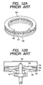
- FIGS. 12A, 12B , 13A and 13B illustrate examples of the formations of conventional vibration type drive units.
- FIG. 12A is a perspective view of a vibrator and a moving element (rotor) which is partly broken away
- FIG. 12B is a cross-sectional view in the rotation axis direction of the vibration type drive unit.
- the reference numeral 101 denotes an annular elastic body made of a metal, and a piezoelectric element 102 is fixed on the bottom surface thereof. Grooves for enlarging vibration displacements are formed on the opposite surface of the piezoelectric element to the elastic body 101. Friction members 103 are arranged on the heads of protrusions formed by the grooves, and a rotor 104 is at a pressure contact with the friction members 103.
- the vibrator is composed of the elastic body 101, the piezoelectric element 102, and the friction members 103.
- a flange portion whose thickness is thinner than the other parts is formed in the inner diameter portion of the elastic body 101 to extend toward the center of the circle, and this flange portion is fixed on a base member 108 of the vibration type drive unit.
- the vibrator can be supported without preventing the progressive wave from being generated.
- a disc spring 106 for pushing the rotor 104 in a direction toward the vibrator is fixed on the rotor 104, and since this disc spring 106 is fixed to a rotary shaft 105, the rotor 104 and the rotary shaft 105 rotate as a unit.
- Bearings 107 for rotatably supporting the rotary shaft 105 are provided on the base member 108. By disposing the plurality of bearings 107 in the axial direction, sway of the rotary shaft 105 is prevented.
- An electrode pattern capable of generating two standing waves which are shifted 1/4 wavelengths mutually is formed on the piezoelectric element 102, and when these two standing waves are excited while the phases thereof are shifted 90 degrees on a time scale, a progressive wave occurs on the surface of the elastic body 102.
- the rotor 104 is rotated and moved as if it were pushed out by the progressive wave.
- This vibration type drive unit has a strong static torque at the time electricity is not turned on and has a strong rotational torque at the time the unit is driven so that it is possible to rotate and move the rotor to a desired position with high accuracy.
- vibration type drive unit shown in FIGS. 12A and 12B is not suitable for being miniaturized so much due to its shape.
- FIGS. 13A and 13B there is a rod type vibration type drive unit shown in FIGS. 13A and 13B in order to obtain a more miniaturized one than the annular type vibration type drive unit shown in FIGS. 12A and 12B .
- FIG. 13A is a perspective view of a vibrator
- FIG. 13B is a cross-sectional view in the rotation axis direction of the vibration type drive unit.
- the reference numerals 201, 202 indicate metal blocks, and a piezoelectric element 203 is disposed therebetween.
- the metal blocks 201, 202 and the piezoelectric element 203 have through holes, and a thread portion is formed on the inner diameter portion of the metal block 201.
- a supporting member 204 of the vibrator is inserted from the metal block 202 side so that the screw threads formed on the supporting member 204 are engaged with the screw threads of the inner diameter portion of the metal block 201.
- the piezoelectric element 203 and the metal block 202 are pressed to be fixed between the metal block 201 and a flange of an end portion of the supporting member 204.
- a narrow portion whose diameter is narrow for increasing vibration displacements is formed on the elastic body 201. Screw threads are formed on the distal end portion of the supporting member 204, a fixing member 208 is engaged with this distal end portion to be fixed by a nut 209, and an output gear 206 is rotatably supported about this fixing member 208.
- a rotor 205 is engaged with the output gear 206 so that when the rotor 205 rotates, the output gear 206 rotates and moves as a unit.
- a pressure spring 207 is disposed between the rotor 205 and the output gear 206 to impart a pressing force toward the elastic body 201 to the rotor 205.
- the vibration type drive unit shown in FIGS. 13A and 13B has a shape simpler than that of the vibration type drive unit shown in FIGS. 12A and 12B , and it can realize miniaturization particularly in the radial direction of the rotor.
- a stator secures a piezoelectric unit polarized from an elastic unit to apply a high frequency voltage to the unit, thereby generating a traveling wave due to bending vibration in the stator.
- the traveling wave generating surface of the stator contacts the traveling wave receiving surface of the rotor, the side of a stationary unit with the shaft of the rotor is pressed by the flange of a bearing in a pressure contacted state, and the rotor receives the traveling wave to be rotated.
- the support of the stator and the support of the rotor are formed in thin disks having smaller thickness than the stator and the rotor.
- a cover having a bearing is coated on a case.
- Document JP 61 277386 describes an ultrasonic wave motor.
- the surface of a first disc piezoelectric transducer is provided with eight divided electrodes, and is polarized in different polarities electrode by electrode.
- a second piezoelectric transducer is also formed in the same way, and both transducers are put together so that the electrode transition of the second piezoelectric transducer may be positioned near the center of the electrode of the first piezoelectric transducer.
- An elastic unit forming a stator by fitting the transducers is provided with the projection of an oscillation-transmitting member and with a central shaft, and a rotor is fitted to organize an ultrasonic wave motor.
- Document US-A-5 457 351 discloses an ultrasonic motor. A position where the projection member is disposed is changed by the product of a vibration displacement distribution of a vibration member composed of an elastic member for exciting the primary elastic progressive waves or more in the radial direction and the tertiary elastic progressive waves or more in the peripheral direction, and a generation force distribution of a vibration member to be caused in accordance with the pressure force so that the motor output is made larger.
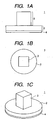
- FIGS. 1A, 1B and 1C show a schematic view of a vibrator constructing a vibration type drive unit according to the present invention.
- FIG. 1A is a side view of the vibrator
- FIG. 1B is a top view in which the vibrator is seen from a direction orthogonal to FIG. 1A
- FIG. 1C is a perspective view of the vibrator.
- the vibrator 1 in FIGS. 1A, 1B and 1C has a structure that a piezoelectric element 4 that is an electromechanical energy conversion element is fixed by gluing or the like to a side surface of a plate-like (disc-like) elastic body 2 made of a material, such as a metal, whose periodic damping loss is small.
- a piezoelectric element 4 that is an electromechanical energy conversion element is fixed by gluing or the like to a side surface of a plate-like (disc-like) elastic body 2 made of a material, such as a metal, whose periodic damping loss is small.
- through holes are formed in the central portions of the elastic body and piezoelectric element so that a screw inserted into the inner portion of the through hole is engaged with a nut as described later.
- a column-like elastic body 3 protruding in a direction perpendicular to a fixing surface of the piezoelectric element 4 is formed on the central portion of a surface of the plate-like elastic body 2 in the side opposite to the surface engaged with the piezoelectric element 4.
- the plate-like elastic body 2 and the column-like elastic body 3 may be integrally formed from the beginning, or they may be formed separately and engaged.
- a method of engagement a method that fixing to a supporting member provided with a thread is executed employing a nut can be thought.
- a step 3a is provided on the inner wall of a through hole arranged in a center portion of the column-like elastic body 3, and a supporting member 5 is inserted into the through hole of the column-like elastic body 3 from the side opposite to the piezoelectric element 4.
- a step 5a is arranged on the middle of the supporting member 5, and this step 5a of the supporting member 5 abuts the step 3a provided on the inner wall of the through hole.
- an end portion 5a of the supporting member 5 is formed to have a length so as to pass through the column-like elastic body 3 and the plate-like elastic body 2 and project from the plate-like elastic body 2 to the outside.
- Screw threads are formed on a distal end portion 5b of the supporting member 5, and by engaging these screw threads with a nut 6 to tighten it, the column-like elastic body 3 and the plate-like elastic body 2 can be fixed.
- a through hole which is a bit larger than the outer diameter of the nut 6 is provided in the central portion of the piezoelectric element 4 so that the nut 6 is arranged in the inner portion of the through hole.
- fixing by welding, gluing, forcible insertion, soldering, or the like may be thought other than the method described above.
- electrode films are formed, for example, on both surfaces of the piezoelectric element 4, the electrode film of a side surface is divided into two electrode films 41, and polarization that is mutually directed oppositely in the thickness direction of the piezoelectric element 4 is imparted to two regions in which the electrode films 41 are formed.
- the same alternating signals are applied to the two electrode films 41, one region of the piezoelectric element 4 expands in the thickness direction, and the other region shrinks in the thickness direction.
- the piezoelectric elements 4 are superimposed so that phases of the electrode films are displaced 90 degrees, and alternating signals whose phases are displaced 90 degrees on a time scale are applied to these piezoelectric elements 4.
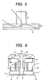
- FIG. 5 in the plate-like elastic body 2, two secondary bending vibrations which are displaced in a direction approximately perpendicular to the fixing surface of the piezoelectric element 4 and whose wavelength directions are mutually orthogonal or approximately orthogonal (one bending vibration's wavelength direction is parallel with the paper surface (shown in the drawing) and the other's wavelength direction is perpendicular to the paper surface (not shown)) are generated.
- the formation pattern of the electrode films of the piezoelectric element 4 is not limited to the one shown in FIGS. 3 and 4 .
- the structure may be that electrodes which are at positions such that their phases are shifted 180 degrees are treated as a pair by dividing a side surface of the piezoelectric element 4 into four and that alternating signals whose phases are shifted 90 degrees on a time scale are applied.
- the polarization direction also is not limited to the thickness direction.
- Various patterns are well known as the electrode film pattern of the piezoelectric element for generating a progressive wave on the surface of the elastic body on which the piezoelectric element is fixed.
- FIG. 6 shows a cross-sectional view of a vibration type drive unit (ultrasonic motor) in which the vibrator is employed.
- the reference numeral 1 denotes the one constructed similarly to the vibrator 1 shown in FIG. 2 , and the column-like elastic body 3 and the plate-like elastic body 2 are fixed by means of the supporting member 5 and the nut 6.
- a sliding member 7a of a rotor 7 is at a pressure contact with the surface of the plate-like elastic body 2 of the side on which the piezoelectric element 4 is not fixed.
- This sliding member 7a has elasticity and is fixed to the rotor 7 to rotate therewith as a unit.
- the reference numeral 8 denotes an output means, such as a gear and the like, which allows the rotor 7 to move in the rotation axis direction and engages with the rotor 7 so as to follow movement with the rotational movement of the rotor 7.
- the reference numeral 9 represents a pushing means, such as a spring and the like, which is disposed between a spring receiving portion of the rotor 7 and the output means 8 and pushes the rotor 7 so as to press it down in the vibrator 1 direction.
- the output means 8 is axially supported on the fixing member 10 fixing the supporting member 5, and the position of the output means 8 in its axial direction is defined by the fixing member 10. Screw threads are formed on a distal end portion 5c of the supporting member 5 of the side which does not engage with the nut 6, and these screw threads are engaged with a nut 11 so that the supporting member 5 is fixed on the fixing member 10.
- the above-described vibrator 1 excites a plurality of bending vibrations with the same degree, i.e. order, in the plate-like elastic body 2 by applying an alternating signal to the piezoelectric element 4.
- a plurality of bending vibrations with the same order which are displaced in a direction approximately parallel to the surface of the piezoelectric element are excited in the column-like elastic body 3 so that the natural frequency of the entire vibrator 1 can be decreased.
- the mass of the vibrator 1 is increased in order to decrease the natural frequency of the vibrator 1
- the column-like elastic body 3 can be disposed to oppose the inner diameter portion of the through hole in the central portion of the rotor.
- the thicknesses of the plate-like elastic body 2 and the piezoelectric element 4 influence the vibrator 1 with respect to the length in the rotation axis direction of the motor, and it is possible to largely contribute to miniaturization in the rotation axis direction of the motor.
- the column-like elastic body 3 can be complexly shaped, it is preferred that the body 3 has a shape such that the body 3 can be accommodated in the inner diameter portion of the rotor 7 without making a useless space.
- the vibrator shown in FIGS. 13A and 13B in order to decrease the natural frequency of the vibrator 1 it is effective to provide a portion whose outer diameter is small on the column-like elastic body 3 as a groove to enlarge the displacement.
- the vibrator 1 which can be usefully arranged in the inner diameter portion of the rotor 7 can be provided.
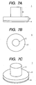
- the shape of the vibrator 1 is not limited to the above-described shape.
- the vibrator 1 shown in FIGS. 7A, 7B and 7C has a column-like shape that the cross-sectional shape of the column-like elastic body 3 is a circle, and there is no problem if the cross-sectional shape is other shapes such as a polygon.
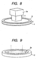
- the vibrator 1 shown in FIG. 8 is the one constructed in such a manner that the mass of a distal end portion of the column-like elastic body 1 is increased. By increasing the mass of the distal end portion of the column-like elastic body 3, the natural frequency of the vibrator 1 can be further decreased, similarly to forming a narrow portion.
- a friction member 12 is fixed on the surface of the plate-like elastic body 2 of the vibrator 1 shown in FIG. 8 .
- the friction member 12 By arranging the friction member 12 on a portion of the plate-like elastic body 2 with which the rotor is brought into pressure contact and slides, it becomes possible to improve the durability of a vibration type drive unit.
- a groove (narrow portion) 2a to enlarge the vibration displacements of secondary bending vibrations which are displaced in a direction approximately perpendicular to the surface of the piezoelectric element is formed on the plate-like elastic body 2 of the vibrator 1 shown in FIG. 9 .
- a plurality of protrusions 2b to be the friction members along the peripheral direction are formed on a portion of the plate-like elastic body 2 shown in FIG. 10 with which the rotor is brought into pressure contact and slides. Since the protrusions 2b are plurally divided to pieces, it is possible to prevent enhancement of the rigidity of a vibrator, which is caused by the friction members, differently from the friction member formed on the annular shape of FIG. 8 .
- the plate-like elastic body 2 shown in FIG. 11 is not provided with any friction member.
Description
- The present invention relates to a structure of a vibration type drive unit such as an ultrasonic motor and the like and, in particular, to an improvement of the structure of a vibrator whose vibration is excited by applying a signal to a piezoelectric element.
- There is a vibration type drive unit, such as an ultrasonic motor and the like, in which a piezoelectric element that is an electromechanical energy conversion element is fixed on an elastic body, for example, made of a metal and an alternating signal is applied to this piezoelectric element to generate a progressive wave on the surface of the elastic body so as to move a moving element (rotor) which is at a pressure contact with the surface of elastic body by the progressive wave.
-
FIGS. 12A, 12B ,13A and 13B illustrate examples of the formations of conventional vibration type drive units. -
FIG. 12A is a perspective view of a vibrator and a moving element (rotor) which is partly broken away, andFIG. 12B is a cross-sectional view in the rotation axis direction of the vibration type drive unit. - The
reference numeral 101 denotes an annular elastic body made of a metal, and apiezoelectric element 102 is fixed on the bottom surface thereof. Grooves for enlarging vibration displacements are formed on the opposite surface of the piezoelectric element to theelastic body 101.Friction members 103 are arranged on the heads of protrusions formed by the grooves, and arotor 104 is at a pressure contact with thefriction members 103. The vibrator is composed of theelastic body 101, thepiezoelectric element 102, and thefriction members 103. - A flange portion whose thickness is thinner than the other parts is formed in the inner diameter portion of the
elastic body 101 to extend toward the center of the circle, and this flange portion is fixed on abase member 108 of the vibration type drive unit. By disposing the flange portion having a spring characteristic on the fixing portion of theelastic body 101 and thebase member 108, the vibrator can be supported without preventing the progressive wave from being generated. Adisc spring 106 for pushing therotor 104 in a direction toward the vibrator is fixed on therotor 104, and since thisdisc spring 106 is fixed to arotary shaft 105, therotor 104 and therotary shaft 105 rotate as a unit.Bearings 107 for rotatably supporting therotary shaft 105 are provided on thebase member 108. By disposing the plurality ofbearings 107 in the axial direction, sway of therotary shaft 105 is prevented. - An electrode pattern capable of generating two standing waves which are shifted 1/4 wavelengths mutually is formed on the
piezoelectric element 102, and when these two standing waves are excited while the phases thereof are shifted 90 degrees on a time scale, a progressive wave occurs on the surface of theelastic body 102. Therotor 104 is rotated and moved as if it were pushed out by the progressive wave. - This vibration type drive unit has a strong static torque at the time electricity is not turned on and has a strong rotational torque at the time the unit is driven so that it is possible to rotate and move the rotor to a desired position with high accuracy.
- However, the vibration type drive unit shown in
FIGS. 12A and 12B is not suitable for being miniaturized so much due to its shape. - Thus, there is a rod type vibration type drive unit shown in
FIGS. 13A and 13B in order to obtain a more miniaturized one than the annular type vibration type drive unit shown inFIGS. 12A and 12B .FIG. 13A is a perspective view of a vibrator, andFIG. 13B is a cross-sectional view in the rotation axis direction of the vibration type drive unit. - The
reference numerals piezoelectric element 203 is disposed therebetween. Themetal blocks piezoelectric element 203 have through holes, and a thread portion is formed on the inner diameter portion of themetal block 201. A supportingmember 204 of the vibrator is inserted from themetal block 202 side so that the screw threads formed on the supportingmember 204 are engaged with the screw threads of the inner diameter portion of themetal block 201. By tightening the supportingmember 204, thepiezoelectric element 203 and themetal block 202 are pressed to be fixed between themetal block 201 and a flange of an end portion of the supportingmember 204. A narrow portion whose diameter is narrow for increasing vibration displacements is formed on theelastic body 201. Screw threads are formed on the distal end portion of the supportingmember 204, afixing member 208 is engaged with this distal end portion to be fixed by anut 209, and anoutput gear 206 is rotatably supported about thisfixing member 208. Arotor 205 is engaged with theoutput gear 206 so that when therotor 205 rotates, theoutput gear 206 rotates and moves as a unit. Apressure spring 207 is disposed between therotor 205 and theoutput gear 206 to impart a pressing force toward theelastic body 201 to therotor 205. - When an alternating signal is applied to the
piezoelectric element 203, two bending vibrations whose amplitude directions are orthogonal or approximately orthogonal to the axial direction and whose amplitude directions are mutually orthogonal or approximately orthogonal are excited, and these two bending vibrations are synthesized so that such a rotational movement as theelastic body 201 draws a circle approximately about the supportingmember 204 occurs. Due to this rotational movement therotor 205 which is at the pressure contact with the surface of the vibrator (that is, the surface of the elastic body 201) rotationally moves as if it were pushed out. - The vibration type drive unit shown in
FIGS. 13A and 13B has a shape simpler than that of the vibration type drive unit shown inFIGS. 12A and 12B , and it can realize miniaturization particularly in the radial direction of the rotor. - However, as seen in
FIGS. 13A and 13B , since the vibrator is constructed in such a way that the piezoelectric element is sandwiched between two elastic bodies, miniaturization for the size in the longitudinal direction of the supporting member of the vibration type drive unit has not been achieved so much compared with the size in the radial direction of the rotor. In order to miniaturize the size in the longitudinal direction of the supporting member, when the vibrator is simply miniaturized, the natural frequency of the vibrator increases and the vibration displacements decrease. Due to the increase of the natural frequency, an element in a drive circuit becomes expensive. Accordingly, it is deemed that there is still room for improvement in miniaturization of the size in the longitudinal direction of the supporting member of the vibration type drive unit without increasing the natural frequency of the vibrator. - Document
JP 62 077068 - Document
JP 61 277386 - Document
US-A-5 457 351 discloses an ultrasonic motor. A position where the projection member is disposed is changed by the product of a vibration displacement distribution of a vibration member composed of an elastic member for exciting the primary elastic progressive waves or more in the radial direction and the tertiary elastic progressive waves or more in the peripheral direction, and a generation force distribution of a vibration member to be caused in accordance with the pressure force so that the motor output is made larger. - It is an object of the present invention to provide an improved vibration type drive unit wherein a miniaturization level thereof is optimized.
- This object is achieved by a vibration type drive unit according to
claim 1. Advantageous further developments are as set out in the dependent claims. - With these structures, without increasing the natural frequency of the vibrator, a further compact vibration type drive unit can be provided.
- Other objects and advantages besides those discussed above shall be apparent to those skilled in the art from the description of a preferred embodiment of the invention which follows. In the description, reference is made to accompanying drawings, which form a part hereof, and which illustrate an example of the invention. Such example, however, is not exhaustive of the various embodiments of the invention, and therefore reference is made to the claims which follow the description for determining the scope of the invention.
-
-
FIGS. 1A, 1B and 1C are schematic views of a vibrator constructing a vibration type drive unit according to the present invention. -
FIG. 2 is a cross-sectional view of the vibrator constructing the vibration type drive unit according to the present invention. -
FIG. 3 is a plan view of one piezoelectric element employed for the vibrator constructing the vibration type drive unit according to the present invention. -
FIG. 4 is a perspective view of a plurality of piezoelectric elements employed for the vibrator constructing the vibration type drive unit according to the present invention. -
FIG. 5 is a view showing displacements of vibrations generated in the vibrator constructing the vibration type drive unit according to the present invention. -
FIG. 6 is a cross-sectional view of the vibration type drive unit according to the present invention. -
FIGS. 7A, 7B and 7C are schematic views of another form of the vibrator constructing the vibration type drive unit according to the present invention. -
FIG. 8 is a schematic view of yet another form of the vibrator constructing the vibration type drive unit according to the present invention. -
FIG. 9 is a perspective view of a plate-like elastic body of the vibrator constructing the vibration type drive unit according to the present invention. -
FIG. 10 is a perspective view of another plate-like elastic body of the vibrator constructing the vibration type drive unit according to the present invention. -
FIG. 11 is a perspective view of yet another plate-like elastic body of the vibrator constructing the vibration type drive unit according to the present invention. -
FIGS. 12A and 12B are cross-sectional views of a conventional annular type vibration type drive unit and a view showing its vibrator and moving element. -
FIGS. 13A and 13B are cross-sectional views of a conventional rod type vibration type drive unit and a view showing its vibrator. -
FIGS. 1A, 1B and 1C show a schematic view of a vibrator constructing a vibration type drive unit according to the present invention. - In the same drawing,
FIG. 1A is a side view of the vibrator,FIG. 1B is a top view in which the vibrator is seen from a direction orthogonal toFIG. 1A, and FIG. 1C is a perspective view of the vibrator. - The
vibrator 1 inFIGS. 1A, 1B and 1C has a structure that apiezoelectric element 4 that is an electromechanical energy conversion element is fixed by gluing or the like to a side surface of a plate-like (disc-like)elastic body 2 made of a material, such as a metal, whose periodic damping loss is small. Other than fixing by gluing, it is possible that through holes are formed in the central portions of the elastic body and piezoelectric element so that a screw inserted into the inner portion of the through hole is engaged with a nut as described later. A column-likeelastic body 3 protruding in a direction perpendicular to a fixing surface of thepiezoelectric element 4 is formed on the central portion of a surface of the plate-likeelastic body 2 in the side opposite to the surface engaged with thepiezoelectric element 4. The plate-likeelastic body 2 and the column-likeelastic body 3 may be integrally formed from the beginning, or they may be formed separately and engaged. As a method of engagement, a method that fixing to a supporting member provided with a thread is executed employing a nut can be thought. - As shown in
FIG. 2 , astep 3a is provided on the inner wall of a through hole arranged in a center portion of the column-likeelastic body 3, and a supportingmember 5 is inserted into the through hole of the column-likeelastic body 3 from the side opposite to thepiezoelectric element 4. Astep 5a is arranged on the middle of the supportingmember 5, and thisstep 5a of the supportingmember 5 abuts thestep 3a provided on the inner wall of the through hole. At this time anend portion 5a of the supportingmember 5 is formed to have a length so as to pass through the column-likeelastic body 3 and the plate-likeelastic body 2 and project from the plate-likeelastic body 2 to the outside. Screw threads are formed on adistal end portion 5b of the supportingmember 5, and by engaging these screw threads with anut 6 to tighten it, the column-likeelastic body 3 and the plate-likeelastic body 2 can be fixed. A through hole which is a bit larger than the outer diameter of thenut 6 is provided in the central portion of thepiezoelectric element 4 so that thenut 6 is arranged in the inner portion of the through hole. It is also possible to have a structure that fixing is performed by screw threads formed on the inner diameter portions of the elastic bodies without providing thestep 3a, similarly to the vibrator shown inFIGS. 13A and 13B . As a method of fixing the column-likeelastic body 3 and the plate-likeelastic body 2, fixing by welding, gluing, forcible insertion, soldering, or the like may be thought other than the method described above. - As shown in
FIG. 3 , electrode films (shaded portions) are formed, for example, on both surfaces of thepiezoelectric element 4, the electrode film of a side surface is divided into twoelectrode films 41, and polarization that is mutually directed oppositely in the thickness direction of thepiezoelectric element 4 is imparted to two regions in which theelectrode films 41 are formed. When the same alternating signals are applied to the twoelectrode films 41, one region of thepiezoelectric element 4 expands in the thickness direction, and the other region shrinks in the thickness direction. - As shown in
FIG. 4 , thepiezoelectric elements 4 are superimposed so that phases of the electrode films are displaced 90 degrees, and alternating signals whose phases are displaced 90 degrees on a time scale are applied to thesepiezoelectric elements 4. Then, as shown inFIG. 5 , in the plate-likeelastic body 2, two secondary bending vibrations which are displaced in a direction approximately perpendicular to the fixing surface of thepiezoelectric element 4 and whose wavelength directions are mutually orthogonal or approximately orthogonal (one bending vibration's wavelength direction is parallel with the paper surface (shown in the drawing) and the other's wavelength direction is perpendicular to the paper surface (not shown)) are generated. At the same time in the column-likeelastic body 3, two primary bending vibrations which are displaced in a direction approximately parallel to the fixing surface of the piezoelectric element and whose displacement directions are mutually orthogonal or approximately orthogonal (one bending vibration's displacement direction is parallel with the paper surface (shown in the drawing) and the other's displacement direction is perpendicular to the paper surface (not shown)) are generated. When these vibrations are synthesized, a primary progressive wave along the circumferential direction of the plate-likeelastic body 2 is excited on the surface of the plate-likeelastic body 2 of the side on which thepiezoelectric element 4 is not fixed. - The formation pattern of the electrode films of the
piezoelectric element 4 is not limited to the one shown inFIGS. 3 and 4 . For example, the structure may be that electrodes which are at positions such that their phases are shifted 180 degrees are treated as a pair by dividing a side surface of thepiezoelectric element 4 into four and that alternating signals whose phases are shifted 90 degrees on a time scale are applied. The polarization direction also is not limited to the thickness direction. Various patterns are well known as the electrode film pattern of the piezoelectric element for generating a progressive wave on the surface of the elastic body on which the piezoelectric element is fixed. - When a moving element such as a rotor is brought into the pressure contact with the surface of the plate-like
elastic body 2 in which the progressive wave is excited, the moving element moves as if it were pushed out by the progressive wave. -
FIG. 6 shows a cross-sectional view of a vibration type drive unit (ultrasonic motor) in which the vibrator is employed. - The
reference numeral 1 denotes the one constructed similarly to thevibrator 1 shown inFIG. 2 , and the column-likeelastic body 3 and the plate-likeelastic body 2 are fixed by means of the supportingmember 5 and thenut 6. A slidingmember 7a of a rotor 7 is at a pressure contact with the surface of the plate-likeelastic body 2 of the side on which thepiezoelectric element 4 is not fixed. This slidingmember 7a has elasticity and is fixed to the rotor 7 to rotate therewith as a unit. Thereference numeral 8 denotes an output means, such as a gear and the like, which allows the rotor 7 to move in the rotation axis direction and engages with the rotor 7 so as to follow movement with the rotational movement of the rotor 7. Thereference numeral 9 represents a pushing means, such as a spring and the like, which is disposed between a spring receiving portion of the rotor 7 and the output means 8 and pushes the rotor 7 so as to press it down in thevibrator 1 direction. The output means 8 is axially supported on the fixingmember 10 fixing the supportingmember 5, and the position of the output means 8 in its axial direction is defined by the fixingmember 10. Screw threads are formed on adistal end portion 5c of the supportingmember 5 of the side which does not engage with thenut 6, and these screw threads are engaged with anut 11 so that the supportingmember 5 is fixed on the fixingmember 10. When for example a D-cut is imparted on theend portion 5c, it is possible to prevent the supportingmember 5 from rotating with respect to the fixingmember 10. Screw holes are provided in the fixingmember 10, and by fixing the fixingmember 10 on a desired portion by means of screws, the vibration type drive unit can be mounted on the desired portion. Aflexible substrate 13 is fixed on the surface of thepiezoelectric element 4 so as to play the role of supplying the alternating signal applied to thepiezoelectric element 4 from an unillustrated power supply. - The above-described
vibrator 1 excites a plurality of bending vibrations with the same degree, i.e. order, in the plate-likeelastic body 2 by applying an alternating signal to thepiezoelectric element 4. By arranging the column-likeelastic body 3 protruding so as to be orthogonal to the surface of thepiezoelectric element 4 on the central portion of the plate-likeelastic body 2, a plurality of bending vibrations with the same order which are displaced in a direction approximately parallel to the surface of the piezoelectric element are excited in the column-likeelastic body 3 so that the natural frequency of theentire vibrator 1 can be decreased. Although it may be thought that the mass of thevibrator 1 is increased in order to decrease the natural frequency of thevibrator 1, when the shape is that the column-likeelastic body 3 is arranged on the central portion of the plate-likeelastic body 2 as shown inFIG. 6 , the column-likeelastic body 3 can be disposed to oppose the inner diameter portion of the through hole in the central portion of the rotor. Thus, only the thicknesses of the plate-likeelastic body 2 and thepiezoelectric element 4 influence thevibrator 1 with respect to the length in the rotation axis direction of the motor, and it is possible to largely contribute to miniaturization in the rotation axis direction of the motor. - Although the column-like
elastic body 3 can be complexly shaped, it is preferred that thebody 3 has a shape such that thebody 3 can be accommodated in the inner diameter portion of the rotor 7 without making a useless space. As the vibrator shown inFIGS. 13A and 13B , in order to decrease the natural frequency of thevibrator 1 it is effective to provide a portion whose outer diameter is small on the column-likeelastic body 3 as a groove to enlarge the displacement. By the shape provided with the displacement enlarging groove, as the natural frequency is decreased, thevibrator 1 which can be usefully arranged in the inner diameter portion of the rotor 7 can be provided. - The shape of the
vibrator 1 is not limited to the above-described shape. For example, thevibrator 1 shown inFIGS. 7A, 7B and 7C has a column-like shape that the cross-sectional shape of the column-likeelastic body 3 is a circle, and there is no problem if the cross-sectional shape is other shapes such as a polygon. Thevibrator 1 shown inFIG. 8 is the one constructed in such a manner that the mass of a distal end portion of the column-likeelastic body 1 is increased. By increasing the mass of the distal end portion of the column-likeelastic body 3, the natural frequency of thevibrator 1 can be further decreased, similarly to forming a narrow portion. - Various types of processing are possible not only for the column-like
elastic body 3 of thevibrator 1 but also for the plate-likeelastic body 2. For example, afriction member 12 is fixed on the surface of the plate-likeelastic body 2 of thevibrator 1 shown inFIG. 8 . By arranging thefriction member 12 on a portion of the plate-likeelastic body 2 with which the rotor is brought into pressure contact and slides, it becomes possible to improve the durability of a vibration type drive unit. - A groove (narrow portion) 2a to enlarge the vibration displacements of secondary bending vibrations which are displaced in a direction approximately perpendicular to the surface of the piezoelectric element is formed on the plate-like
elastic body 2 of thevibrator 1 shown inFIG. 9 . - A plurality of
protrusions 2b to be the friction members along the peripheral direction are formed on a portion of the plate-likeelastic body 2 shown inFIG. 10 with which the rotor is brought into pressure contact and slides. Since theprotrusions 2b are plurally divided to pieces, it is possible to prevent enhancement of the rigidity of a vibrator, which is caused by the friction members, differently from the friction member formed on the annular shape ofFIG. 8 . - The plate-like
elastic body 2 shown inFIG. 11 is not provided with any friction member.
Claims (3)
- A vibration type drive unit comprising:a vibrator (1) made of an elastic body (2, 3) comprising a plate-like elastic body (2) and a column-like elastic body (3),a piezoelectric element (4) fixed to a first surface of the plate-like elastic body (2), the column-like elastic body (3) being formed on a central portion of a second surface of the plate-like elastic body (2), which is opposite to said first surface,a rotor (7) which is in contact with said second surface of the plate-like elastic body (2), anda supporting member (5) fixed within the column-like elastic body (3) and supporting the vibrator (1) so that by applying an alternating signal to the piezoelectric element (4), a progressive wave is generated on said second surface of the plate-like elastic body (2) to move the rotor (7),characterized in that
it comprises a fitting member (6) which fits into the supporting member (5) to fix the vibrator (1) to the supporting member (5), and
the column-like elastic body (3) faces an inner wall of the rotor (7), said inner wall having a larger diameter than the outer diameter of the column-like elastic body (3),
wherein the piezoelectric element (4) is disposed around the fitting member (6). - A vibration type drive unit according to claim 1, wherein the rotor (7) rotates about the supporting member (5).
- A vibration type drive unit according to claim 1, wherein a displacement direction of a vibration generated in the plate-like elastic body (2) is perpendicular to a fixing surface of the piezoelectric element (4) and a displacement direction of a vibration generated in the column-like elastic body (3) is parallel to the fixing surface of the piezoelectric element (4), wherein the vibration generated in the plate-like elastic body (2) is a secondary bending vibration and the vibration generated in the column-like elastic body (3) is a primary bending vibration.
Applications Claiming Priority (2)
| Application Number | Priority Date | Filing Date | Title |
|---|---|---|---|
| JP2002204343A JP3566711B2 (en) | 2002-07-12 | 2002-07-12 | Vibration wave drive |
| JP2002204343 | 2002-07-12 |
Publications (3)
| Publication Number | Publication Date |
|---|---|
| EP1381092A2 EP1381092A2 (en) | 2004-01-14 |
| EP1381092A3 EP1381092A3 (en) | 2006-06-07 |
| EP1381092B1 true EP1381092B1 (en) | 2009-09-23 |
Family
ID=29728537
Family Applications (1)
| Application Number | Title | Priority Date | Filing Date |
|---|---|---|---|
| EP03015806A Expired - Lifetime EP1381092B1 (en) | 2002-07-12 | 2003-07-10 | Vibration type drive unit |
Country Status (4)
| Country | Link |
|---|---|
| US (1) | US7015623B2 (en) |
| EP (1) | EP1381092B1 (en) |
| JP (1) | JP3566711B2 (en) |
| DE (1) | DE60329353D1 (en) |
Families Citing this family (8)
| Publication number | Priority date | Publication date | Assignee | Title |
|---|---|---|---|---|
| JP4624750B2 (en) * | 2004-09-17 | 2011-02-02 | 次郎丸 辻野 | Ultrasonic composite vibrator |
| KR100631884B1 (en) | 2004-11-24 | 2006-10-09 | 삼성전기주식회사 | Flat Plate Piezoelectric Ultrasonic Motor |
| KR100680307B1 (en) * | 2005-05-20 | 2007-02-07 | 삼성전기주식회사 | Piezoelectric Vibrator and Ultrasonic Motor Having Piezoelectric Vibrator |
| JP5049523B2 (en) * | 2006-06-29 | 2012-10-17 | キヤノン株式会社 | Vibration wave drive |
| JP5700186B1 (en) * | 2013-07-08 | 2015-04-15 | ソニー株式会社 | Curing condition determination method, circuit device manufacturing method, and circuit device |
| JP6598488B2 (en) * | 2015-04-10 | 2019-10-30 | キヤノン株式会社 | Vibration wave motor |
| JP2019213255A (en) * | 2018-05-31 | 2019-12-12 | セイコーエプソン株式会社 | Rotation-linear motion conversion device |
| JPWO2022220059A1 (en) * | 2021-04-12 | 2022-10-20 |
Family Cites Families (10)
| Publication number | Priority date | Publication date | Assignee | Title |
|---|---|---|---|---|
| AT384912B (en) * | 1982-04-16 | 1988-01-25 | Ki Polt I | PIEZOELECTRIC MOTOR |
| JPH0636674B2 (en) | 1985-06-03 | 1994-05-11 | 松下電器産業株式会社 | Ultrasonic motor |
| JPS6277068A (en) | 1985-08-31 | 1987-04-09 | Shinsei Kogyo:Kk | Improvement in support of surface wave motor |
| US4959580A (en) * | 1987-02-28 | 1990-09-25 | Kievsky Politekhnichesky Institut Imeni | Piezoelectric motor |
| EP0458638B1 (en) * | 1990-05-24 | 1997-04-09 | Canon Kabushiki Kaisha | Vibration wave driven motor |
| JP2925272B2 (en) * | 1990-08-31 | 1999-07-28 | キヤノン株式会社 | Vibration wave motor |
| JP3171887B2 (en) * | 1991-10-21 | 2001-06-04 | キヤノン株式会社 | Vibration wave drive |
| US5457351A (en) | 1991-10-31 | 1995-10-10 | Matsushita Electric Industrial Co., Ltd. | Ultrasonic motor |
| JP3526298B2 (en) * | 2001-01-22 | 2004-05-10 | キヤノン株式会社 | Vibrating body and vibration wave driving device |
| US6867532B2 (en) * | 2003-07-17 | 2005-03-15 | The Brady Group Inc. | Long life piezoelectric drive and components |
-
2002
- 2002-07-12 JP JP2002204343A patent/JP3566711B2/en not_active Expired - Fee Related
-
2003
- 2003-07-03 US US10/612,152 patent/US7015623B2/en not_active Expired - Fee Related
- 2003-07-10 EP EP03015806A patent/EP1381092B1/en not_active Expired - Lifetime
- 2003-07-10 DE DE60329353T patent/DE60329353D1/en not_active Expired - Lifetime
Also Published As
| Publication number | Publication date |
|---|---|
| EP1381092A3 (en) | 2006-06-07 |
| EP1381092A2 (en) | 2004-01-14 |
| DE60329353D1 (en) | 2009-11-05 |
| JP2004048932A (en) | 2004-02-12 |
| US20040007946A1 (en) | 2004-01-15 |
| JP3566711B2 (en) | 2004-09-15 |
| US7015623B2 (en) | 2006-03-21 |
Similar Documents
| Publication | Publication Date | Title |
|---|---|---|
| US6888288B2 (en) | Vibration member and vibration wave driving apparatus using the vibration member | |
| CN1870413B (en) | Vibrational actuator and method for driving vibrational actuator | |
| EP1381092B1 (en) | Vibration type drive unit | |
| JP5211463B2 (en) | Vibration actuator | |
| US7825566B2 (en) | Ultrasonic actuator and method for manufacturing piezoelectric deformation portion used in the same | |
| JP5049523B2 (en) | Vibration wave drive | |
| JPH0724416A (en) | Ultrasonic vibrator | |
| US5777424A (en) | Vibration actuator | |
| JPH06189569A (en) | Ultrasonic motor | |
| JP3902955B2 (en) | Vibration body and vibration wave drive device | |
| JP2003164171A (en) | Oscillatory wave drive unit | |
| JP3283832B2 (en) | Ultrasonic motor | |
| JP2978382B2 (en) | Ultrasonic motor stator | |
| JP2683587B2 (en) | Ultrasonic motor | |
| JP2005287246A (en) | Oscillator and oscillation wave motor | |
| JPH0681523B2 (en) | Vibration wave motor | |
| JP2004112924A (en) | Oscillatory wave drive unit | |
| JPH0837785A (en) | Ultrasonic motor and electronic apparatus provided with ultrasonic motor | |
| JP4784154B2 (en) | Vibration actuator | |
| JPH02146967A (en) | Ultrasonic actuator | |
| JPH06276767A (en) | Ultrasonic motor | |
| JP2002369559A (en) | Oscillatory wave motor | |
| JPH10263477A (en) | Vibration-type drive device and device with vibration-type drive device as drive source | |
| JPH07163165A (en) | Ultrasonic motor and device employing it | |
| JP2009044952A (en) | Ultrasonic actuator, magnetic recorder |
Legal Events
| Date | Code | Title | Description |
|---|---|---|---|
| PUAI | Public reference made under article 153(3) epc to a published international application that has entered the european phase |
Free format text: ORIGINAL CODE: 0009012 |
|
| AK | Designated contracting states |
Kind code of ref document: A2 Designated state(s): AT BE BG CH CY CZ DE DK EE ES FI FR GB GR HU IE IT LI LU MC NL PT RO SE SI SK TR |
|
| AX | Request for extension of the european patent |
Extension state: AL LT LV MK |
|
| PUAL | Search report despatched |
Free format text: ORIGINAL CODE: 0009013 |
|
| AK | Designated contracting states |
Kind code of ref document: A3 Designated state(s): AT BE BG CH CY CZ DE DK EE ES FI FR GB GR HU IE IT LI LU MC NL PT RO SE SI SK TR |
|
| AX | Request for extension of the european patent |
Extension state: AL LT LV MK |
|
| 17P | Request for examination filed |
Effective date: 20061207 |
|
| AKX | Designation fees paid |
Designated state(s): DE FR GB |
|
| 17Q | First examination report despatched |
Effective date: 20070614 |
|
| GRAP | Despatch of communication of intention to grant a patent |
Free format text: ORIGINAL CODE: EPIDOSNIGR1 |
|
| GRAS | Grant fee paid |
Free format text: ORIGINAL CODE: EPIDOSNIGR3 |
|
| GRAA | (expected) grant |
Free format text: ORIGINAL CODE: 0009210 |
|
| AK | Designated contracting states |
Kind code of ref document: B1 Designated state(s): DE FR GB |
|
| REG | Reference to a national code |
Ref country code: GB Ref legal event code: FG4D |
|
| REF | Corresponds to: |
Ref document number: 60329353 Country of ref document: DE Date of ref document: 20091105 Kind code of ref document: P |
|
| PLBE | No opposition filed within time limit |
Free format text: ORIGINAL CODE: 0009261 |
|
| STAA | Information on the status of an ep patent application or granted ep patent |
Free format text: STATUS: NO OPPOSITION FILED WITHIN TIME LIMIT |
|
| 26N | No opposition filed |
Effective date: 20100624 |
|
| REG | Reference to a national code |
Ref country code: FR Ref legal event code: ST Effective date: 20110331 |
|
| PG25 | Lapsed in a contracting state [announced via postgrant information from national office to epo] |
Ref country code: FR Free format text: LAPSE BECAUSE OF NON-PAYMENT OF DUE FEES Effective date: 20100802 |
|
| PGFP | Annual fee paid to national office [announced via postgrant information from national office to epo] |
Ref country code: DE Payment date: 20160731 Year of fee payment: 14 Ref country code: GB Payment date: 20160727 Year of fee payment: 14 |
|
| REG | Reference to a national code |
Ref country code: DE Ref legal event code: R119 Ref document number: 60329353 Country of ref document: DE |
|
| GBPC | Gb: european patent ceased through non-payment of renewal fee |
Effective date: 20170710 |
|
| PG25 | Lapsed in a contracting state [announced via postgrant information from national office to epo] |
Ref country code: DE Free format text: LAPSE BECAUSE OF NON-PAYMENT OF DUE FEES Effective date: 20180201 Ref country code: GB Free format text: LAPSE BECAUSE OF NON-PAYMENT OF DUE FEES Effective date: 20170710 |