EP1381083A2 - Method and apparatus for removing heat from a circuit - Google Patents
Method and apparatus for removing heat from a circuit Download PDFInfo
- Publication number
- EP1381083A2 EP1381083A2 EP03254283A EP03254283A EP1381083A2 EP 1381083 A2 EP1381083 A2 EP 1381083A2 EP 03254283 A EP03254283 A EP 03254283A EP 03254283 A EP03254283 A EP 03254283A EP 1381083 A2 EP1381083 A2 EP 1381083A2
- Authority
- EP
- European Patent Office
- Prior art keywords
- coolant
- phase
- circuit component
- thermally conductive
- conductive part
- Prior art date
- Legal status (The legal status is an assumption and is not a legal conclusion. Google has not performed a legal analysis and makes no representation as to the accuracy of the status listed.)
- Granted
Links
Images

Classifications
-
- H—ELECTRICITY
- H01—ELECTRIC ELEMENTS
- H01Q—ANTENNAS, i.e. RADIO AERIALS
- H01Q21/00—Antenna arrays or systems
- H01Q21/0087—Apparatus or processes specially adapted for manufacturing antenna arrays
-
- H—ELECTRICITY
- H01—ELECTRIC ELEMENTS
- H01Q—ANTENNAS, i.e. RADIO AERIALS
- H01Q1/00—Details of, or arrangements associated with, antennas
- H01Q1/02—Arrangements for de-icing; Arrangements for drying-out ; Arrangements for cooling; Arrangements for preventing corrosion
-
- H—ELECTRICITY
- H01—ELECTRIC ELEMENTS
- H01Q—ANTENNAS, i.e. RADIO AERIALS
- H01Q21/00—Antenna arrays or systems
- H01Q21/0006—Particular feeding systems
- H01Q21/0025—Modular arrays
-
- H—ELECTRICITY
- H10—SEMICONDUCTOR DEVICES; ELECTRIC SOLID-STATE DEVICES NOT OTHERWISE PROVIDED FOR
- H10W—GENERIC PACKAGES, INTERCONNECTIONS, CONNECTORS OR OTHER CONSTRUCTIONAL DETAILS OF DEVICES COVERED BY CLASS H10
- H10W40/00—Arrangements for thermal protection or thermal control
- H10W40/70—Fillings or auxiliary members in containers or in encapsulations for thermal protection or control
- H10W40/73—Fillings or auxiliary members in containers or in encapsulations for thermal protection or control for cooling by change of state
-
- H—ELECTRICITY
- H10—SEMICONDUCTOR DEVICES; ELECTRIC SOLID-STATE DEVICES NOT OTHERWISE PROVIDED FOR
- H10W—GENERIC PACKAGES, INTERCONNECTIONS, CONNECTORS OR OTHER CONSTRUCTIONAL DETAILS OF DEVICES COVERED BY CLASS H10
- H10W72/00—Interconnections or connectors in packages
- H10W72/50—Bond wires
- H10W72/551—Materials of bond wires
- H10W72/552—Materials of bond wires comprising metals or metalloids, e.g. silver
- H10W72/5522—Materials of bond wires comprising metals or metalloids, e.g. silver comprising gold [Au]
-
- H—ELECTRICITY
- H10—SEMICONDUCTOR DEVICES; ELECTRIC SOLID-STATE DEVICES NOT OTHERWISE PROVIDED FOR
- H10W—GENERIC PACKAGES, INTERCONNECTIONS, CONNECTORS OR OTHER CONSTRUCTIONAL DETAILS OF DEVICES COVERED BY CLASS H10
- H10W90/00—Package configurations
- H10W90/701—Package configurations characterised by the relative positions of pads or connectors relative to package parts
- H10W90/751—Package configurations characterised by the relative positions of pads or connectors relative to package parts of bond wires
- H10W90/754—Package configurations characterised by the relative positions of pads or connectors relative to package parts of bond wires between a chip and a stacked insulating package substrate, interposer or RDL
Definitions
- This invention relates in general to techniques for cooling circuitry and, more particularly, to a method and apparatus for efficiently removing heat from a circuit which generates relatively large amounts of heat.
- circuits produce very little heat, and can be operated with a passive cooling technique, such as convection cooling.
- a passive cooling technique such as convection cooling.
- circuits which produce extremely large amounts of heat, and require some sort of active cooling.
- One example is a high-power phased array antenna system, which consumes large amounts of electrical power, typically on the order of tens of thousands of watts.
- phased array antenna systems commonly include monolithic microwave integrated circuits (MMICs), which consume substantial amounts of power, and which generate substantial amounts of heat.
- MMICs monolithic microwave integrated circuits
- Pre-existing systems of this type usually include MMICs that need cooling for a thermal density of no more than about 100 Watts/in 2 .
- MMIC devices which consume substantially higher amounts of power and which dissipate substantially greater amounts of heat.
- GaN MMIC gallium nitride
- GaAs gallium arsenide
- the typical thermal density can be on the order of at least 400 Watts/in 2 , when the radio frequency duty cycle is at 100%.
- pre-existing techniques for cooling phased array antenna systems have been generally adequate for their intended purposes, they use a single phase coolant, such as a refrigeration-cooled polyalphaolefin (PAO).
- PAO refrigeration-cooled polyalphaolefin
- Such a pre-existing cooling system with a single-phase coolant is only capable of handling thermal densities up to about 100 Watts/in 2 . Consequently, these pre-existing cooling systems and techniques are not entirely satisfactory for the levels of heat dissipated by next-generation technology in phased array antenna systems.
- a need has arisen for a method and apparatus for providing more effective cooling of heat-generating circuit components.
- a method and apparatus are provided to address this need, and involve: operating a circuit which includes a heat-generating circuit component; and guiding a two-phase coolant along a path which brings the coolant into direct physical contact with the circuit component or with a highly thermally conductive part which is thermally coupled to the circuit component.
- the coolant absorbs heat generated by the circuit component, at least part of the coolant changing from a first phase to a second phase in response to heat absorbed from the circuit component, where the second phase is different from the first phase.
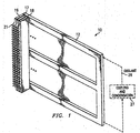
- FIGURE 1 is a diagrammatic perspective view of part of an apparatus which is a phased array antenna system 10.
- the antenna system 10 includes a frame or chassis 12.
- the chassis 12 supports a plurality of modules of a type commonly known as slats, three of which are shown in FIGURE 1 at 16-18. In an operational configuration, a larger number of slats would be installed in the frame 12, so that the frame 12 is effectively filled with slats.
- the slats are all identical, including the three slats shown at 16-18.
- Each slat has, along an edge opposite from the frame 12, a row of outwardly projecting antenna elements 21.
- the antenna elements 21 on all of the slats collectively define a two-dimensional array of antenna elements.
- Each slat includes circuitry with transmit and receive capabilities, and this circuitry is operationally coupled to the antenna elements 21 on that slat.
- the frame 12 carries electrical signals and coolant to and from each of the slats, in a manner which is known in the art and which is therefore not illustrated and described here in detail.
- FIGURE 1 diagrammatically shows a cooling and condensation system 27 which is capable of cooling a coolant in its vapor phase, so as to return the coolant to its liquid phase. Coolant from the frame 12 is circulated through the system 27 along a path which is indicated diagrammatically in FIGURE 1 by reference numeral 26.
- the transmit/receive circuitry includes monolithic microwave integrated circuits (MMICs), which need active cooling that can remove heat at a rate which is less than about 100 Watts/in 2 .
- Newer MMICs include gallium nitride (GaN) technology, and dissipate significantly greater amounts of heat, for example 500 Watts/in 2 .
- the antenna system 10 uses GaN MMIC technology, and includes a cooling configuration capable of efficiently removing heat at rate of 500 Watts/in 2 .
- the cooling arrangement provided for the antenna system 10 of FIGURE 1 is capable of removing heat at rates up to approximately 1,000 Watts/in 2 .
- FIGURE 2 is a diagrammatic exploded fragmentary perspective view of the slat 16 of FIGURE 1.
- the slat 16 includes a slat member 41, a cooling plate 42, and a cover plate 43, the cooling plate 42 being sandwiched between the slat member 41 and the cover plate 43.
- the slat member 41, cooling plate 42 and cover plate 43 are each made of aluminum silicon carbide (AlSiC), due in part to the fact that it has a coefficient of thermal expansion (CTE) comparable to that of other components within the slat, so as to avoid thermally-induced structural stress.
- AlSiC aluminum silicon carbide
- CTE coefficient of thermal expansion
- one or more of the parts 41-43 could alternatively be made of some other suitable material.
- the slat member 41 has a row of the antenna elements 21 supported thereon.
- a multi-layer circuit board 47 is supported on a side of the slat member 41 which faces the cooling plate 42.
- the circuit board 47 is electrically coupled to the frame 12 (FIGURE 1) through connectors in a manner which is known in the art and therefore not illustrated and described here in detail.
- the circuit board 47 has, on the side thereof which is not visible in FIGURE 2, a plurality of radio frequency (RF) probes that are disposed along the edge adjacent the antenna elements 21.
- RF radio frequency
- the circuit board 47 has mounted thereon a vertical column of transmit/receive modules, one of which is identified in FIGURE 2 by reference numeral 51. Each of the transmit/receive modules is associated with a respective one of the antenna elements 21.
- the transmit/receive modules are identical, and therefore only the module 51 is discussed below in further detail.
- the module 51 includes a ceramic base plate 52, which is hermetically sealed along its peripheral edge to a ceramic cover 53, thereby defining a module housing.
- the module 51 includes within this housing a circuit board, which has a GaN MMIC 56 mounted thereon.
- the side of the MMIC 56 which is visible in FIGURE 2 is the side commonly referred to as the active-junction side.
- the circuit board within the module 51 is generally not visible in FIGURE 2.
- the circuitry provided on the circuit board within each module has a configuration of a type which is known in the art, and which is therefore not described here in detail.
- the cover 53 of the module 51 has a rectangular opening 61, which is aligned with the MMIC 56 and serves as an inlet port through which coolant can enter the module 51, as discussed in more detail later.
- the cover 53 has near its opposite lower corners two output ports 62 and 63, through which coolant exits the module 51, as discussed later.
- the circuit board within the module 51 is electrically coupled to the multi-layer circuit board 47.
- the facing surfaces of the circuit board 47 and the base plate 52 each have a plurality of not-illustrated pads, and respective pairs of these pads are electrically coupled to each other by a grid of solder drops or balls, in a configuration of the type generally known in the art as a ball grid array.
- the base plate 52 of the module 51 has a plurality of not-illustrated vias, which each extend through it in a manner facilitating a hermetic seal. One end of each via is coupled to one of the pads provided on the base plate 52, and the other end of each via is electrically coupled in some suitable manner to the circuit board in the module 51.
- a seal exists between the cooling plate 42 and each of the modules provided on the slat member 41, including the module 51. In the disclosed embodiment, this is effected through the use of a low-temperature solder provided between the cooling plate 42 and each of the modules.
- the seal could alternatively be effected in some other suitable manner, for example with a compression seal.
- Still another alternative approach is to use a seal which extends along the periphery of the cooling plate 42 and the periphery of the group of modules, in a manner so that the inlet and outlet ports 61-63 are not sealed relative to each, but are all sealed relative to structure external to the seal.
- the cooling plate 42 has, on the side thereof opposite from the slat member 41, a configuration of shallow channels or grooves that are formed through machining, casting or molding.
- This network of channels includes an inlet port 72, which can be operatively coupled to a coolant supply line located within the frame 12 (FIGURE 1), for example through use of a quick-disconnect coupling of a type which is known in the art and therefore not shown and described in here detail.
- the use of quick-disconnect couplings permits a slat to be removed and replaced without draining coolant from the entire system.
- the inlet port 72 leads to a highpressure inlet channel 73, which in turn communicates with a plurality of orifices, two of which are designated in FIGURE 2 by respective reference numerals 76 and 77.
- a plurality of orifices two of which are designated in FIGURE 2 by respective reference numerals 76 and 77.
- the illustrated orifices are all the same size. However, as shown diagrammatically by the broken line 78, it would alternatively be possible for some of the orifices to be larger or smaller than others, so that some of the modules on the circuit board 47 intentionally receive more or less coolant than other modules, thereby supplying more or less coolant to modules which need proportionally more or less cooling.
- the cooling plate 42 also has several pairs of return openings 83 and 84, which each extend transversely through the cooling plate 42 and which each communicate with a respective one of the outlet ports 62 and 63 in a respective one of the modules.
- Each pair of return openings 83 and 84 communicates with a respective low-pressure return channel 86.
- the return channels 86 all lead to a somewhat deeper channel 88, which serves as a low-pressure collection chamber. Coolant from the collection chamber 88 travels from the cooling plate 42 to a not-illustrated outlet port, which is coupled to the frame 12 (FIGURE 1) by a not-illustrated quick-disconnect fitting of a known type.
- the cover 43 has its peripheral edges sealed with respect to peripheral edges of the cooling plate 42, for example by brazing or welding, or by a not-illustrated gasket. Further, the peripheral edges of the cooling plate 42 are sealed in a similar manner to peripheral edges of the slat member 41.
- FIGUREs 1 and 2 effects what can be referred to as "front side" cooling of the MMICs 56 in each module, in that the coolant directly contacts the active-junction side of each MMIC.
- a coolant which is thermally conductive but electrically non-conductive.
- the embodiment of FIGURES 1 and 2 uses as the coolant a fluorinert of a known type, such as that commercially available as FC-77. Due to the fact that the coolant directly engages the MMIC, without intervening structure, the temperature differential between the coolant and active-junction of the MMICs is minimized, which helps to keep the junction temperatures of the MMICs low, which in turn increases the operational lifetime and reliability of the MMICs.
- coolant in a liquid phase is supplied through the frame 12 to each of the slats, including the slat 16.
- the portion of the coolant which enters the slat 16 flows into the cooling plate 42 through the inlet 72.
- This coolant then travels through the inlet channel 73, where it splits so that a respective portion of it passes through each of the orifices, including the orifices shown at 76 and 77.
- respective portions of the coolant each reach and pass through a respective group of the openings 81, and then each flow through the opening 61 in a respective one of the modules, as indicated diagrammatically in FIGURE 2 by the broken line 96.
- the coolant After entering each module through the associated opening 61, the coolant directly contacts the exposed active-junction side of the MMIC 56 in that module, and absorbs heat from the MMIC 56. Due to this absorption of heat, part or all of the coolant in that module boils and changes from its liquid phase to its vapor phase. This phase change is inherently associated with absorption of a substantial amount of heat by the coolant.
- the coolant inside the module including vapor and possibly some liquid, then flows within the module from the region of the opening 61 toward the outlet ports 62 and 63, absorbing heat from other components on the circuit board within the module.
- each module respective portions of the coolant exit the module through the outlet ports 62 and 63 of that module, and then respectively pass through the associated pair of return openings 83 and 84 in the cooling plate 42, as indicated diagrammatically in FIGURE 2 by the broken lines 97 and 98.
- the portions of the coolant passing through each pair of the return openings 83 and 84 then enter a respective one of the channels 86, where they travel to the collection chamber 88.
- the coolant travels to the not-illustrated outlet port for the slat 16.
- the coolant which exits the slat 16 through the outlet port flows through a channel provided within the frame 12, and then travels along the path 26 through the cooling and condensation system 27, where it is cooled and returned to a liquid phase.
- This cooled liquid coolant is then routed back into the frame 12, where it is again distributed among the inlet ports 72 of the slats.
- the cooling plate 42 is shown as being sandwiched between the slat member 41 and the cover plate 43.
- the cover plate 43 can be replaced with a cooling plate and a slat member which are mirror images of the cooling plate 42 and slat member 41, resulting in a single slat that has a central cooling arrangement sandwiched between and serving two vertical columns of antenna elements and transmit/receive modules.
- FIGURES 1 and 2 uses a fluorinert as the coolant, because a fluorinert is thermally conductive but electrically non-conductive.
- a fluorinert is thermally conductive but electrically non-conductive.
- a significant part of the cooling effect is obtained by the phase change of the coolant, from its liquid phase to its vapor phase.
- the amount of heat absorbed by a coolant as it changes from a liquid to a vapor is known as its latent heat of vaporization.
- coolants which have a latent heat of vaporization substantially higher than that of the fluorinert used in FIGUREs 1 and 2.
- these other coolants change from a liquid to a vapor, they absorb substantially more heat per unit of volume than a fluorinert.
- water has a latent heat of vaporization which is higher than that of virtually any other suitable coolant, and which is about 20 times the latent heat of vaporization of a typical fluorinert.
- the volume of a fluorinert which must flow in order to remove a specified amount of heat is about 20 times the volume of water that must flow in order to remove the same amount of heat.
- coolants that have latent heats of vaporization greater than a fluorinert include methanol, ammonia, a mixture of water and ethylene glycol, and a mixture of water and methanol.
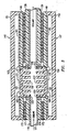
- FIGURE 3 is a diagrammatic fragmentary sectional top view of a portion of a slat which is an alternative embodiment of the slat 16 shown in FIGURE 2.
- a cooling plate 110 made of AlSiC has several passageways extending through it, one of which is visible at 111 in FIGURE 3.
- a coolant is caused to flow through the passageway 111, as indicated diagrammatically by broken lines in FIGURE 3.
- the distribution of coolant to respective passageways 111 is effected through respective not-illustrated orifices, in a manner similar to that described above in association with the embodiment of FIGURE 2.
- the coolant is water, but could alternatively be ammonia, methanol, a mixture of water and methanol, a mixture of water and ethylene glycol, a fluorinert, or any other suitable two-phase coolant.
- the cooling plate 110 has openings 116 and 117 provided through opposite sides thereof.
- a highly thermally conductive spreader part 121 is fixedly securing within the opening 116 by a ring of a sealant 123.
- the sealant 123 can be any suitable known sealant, and prevents coolant from leaking out of the passageway 111 around the edges of the thermally conductive part 121.
- an identical spreader part 122 is fixedly secured within the opening 117 by a ring of sealant 124.
- the thermally conductive parts 121 and 122 are each made of synthetic diamond, which is highly thermally conductive, but they could alternatively be made of any other suitable material, one example of which is beryllium oxide (BeO).
- the thermally conductive parts 121 and 122 each have a plurality of fins or projections 126 or 127 that extend inwardly, in a direction toward the passageway 111.
- the ends of the projections 126 and 127 may be disposed outwardly of, even with the edges of, or within the passageway 111.
- the length and position of the projections 126 and 127 ensures that the coolant will be properly distributed so as to make contact with the projections 126 and 127.
- the projections 126 and 127 result in a substantial increase in the amount of surface area on the thermally conductive parts 121 and 122 which engages the coolant, in comparison to a not-illustrated configuration in which each of the thermally conductive parts has just a flat inner surface that engages the coolant. Since the projections 126 and 127 significantly increase the amount of surface area on the parts 121 and 122 which engages the coolant, they also significantly increase the rate at which heat can be transferred from the thermally conductive parts 121 and 122 to the
- the thermally conductive parts 121 and 122 each have a flat surface on a side thereof opposite from the projections 126 and 127.
- a respective MMIC 131 or 132 is fixedly mounted on each of these flat surfaces, with the back side of each MMIC 131 or 132 facing toward and the active-junction side of each MMIC facing away from the associated thermally conductive part 121 or 122.
- the MMICs 131 and 132 can be secured in place by a known epoxy which is highly thermally conductive, or in any other suitable manner which ensures that the MMICs 131 and 132 are in substantially direct thermal communication with the thermally conductive parts 121 and 122, so as to achieve a very high level of thermal conductivity between each MMIC and the associated thermally conductive part.
- FIGURE 3 shows the thermally conductive parts 121 and 122 which are disposed between the coolant and the MMICs 131 and 132, it would alternatively be possible for the coolant to directly contact the back sides of the MMICs, even if the coolant is electrically conductive.
- the thermally conductive parts could have openings therethrough which expose the back sides of the MMICs to the coolant, in which case the parts 121 and 122 could be either thermally conductive or non-conductive.
- the back sides could be roughened to facilitate heat transfer, and/or could have integral projections similar to the projections 126 and 127 on the thermally conductive parts.
- two multi-layer circuit boards 138 and 139 are supported on opposite sides of the cooling plate 110.
- Each of the circuit boards has an opening therethrough, and a respective one of the thermally conductive parts 121 and 122 extends through each such opening.
- Two transmit/receive modules 146 and 147 are disposed on opposites of the cooling plate 110.
- the modules 146 and 147 are each generally analogous to the type of transmit/receive module shown at 51 in FIGURE 2, although there are some differences.
- each of the transmit/receive modules 146 and 147 includes a housing defined by a ceramic base plate 148 or 149 that has its peripheral edges fixedly and sealingly secured to edges of a ceramic cover 151 or 152, for example by brazing.
- the base plates 148 and 149 each have therethrough a stepped opening 153 or 154, which matingly engages a corresponding stepped opening in a respective one of the thermally conductive parts 121 and 122.
- the base plates 148 and 149 are fixedly and sealingly secured to the respective thermally conductive parts 121 or 122, for example by brazing.
- the housings of the modules 146 and 147 are each hermetically sealed.
- Each of the transmit/receive modules 146 and 147 has therein a respective circuit board 161 or 162, which in turn has transmit/receive circuitry of a known type thereon, and which has therethrough an opening that accommodates the associated MMIC 131 or 132, and an end of the corresponding thermally conductive part 121 or 122.
- the MMICs 131 and 132 are each electrically coupled to the associated circuit board 161 or 162 by a plurality of gold wires, for example as indicated diagrammatically at 163 and 164.
- the facing surfaces of the base plate 148 and the multi-layer circuit board 138 each have a plurality of pads.
- a plurality of balls of solder arranged in what is commonly known as a ball grid array, are provided between the base plate 148 and the circuit board 138.
- the solder balls 171 of the ball grid array are surrounded by an underfill 173 of a type known in the art, which is not electrically conductive.
- facing surfaces of the base plate 149 and the multi-layer circuit board 139 have pads which are electrically coupled to each other by solder balls 172 of a further ball grid array.
- the solder balls 172 in this second ball grid array are surrounded by an associated underfill 174, which is electrically non-conductive.
- the above-mentioned pads on the base plate 148 are electrically coupled to the transmit/receive circuit board 161 in a suitable manner, for example by not-illustrated vias which extend through the base plate 148 in a manner that effects a hermetic seal for the housing of the module 146.
- the pads on the base plate 149 are electrically coupled to the transmit/receive circuit board 162 in a suitable manner, for example by not-illustrated vias which extend through the base plate 149 in a manner that effects a hermetic seal for the housing of the module 147.
- the MMICs 131 and 132 each generate substantial amounts of heat, the majority of which is transferred to a respective one of the highly thermally conductive parts 121 and 122.
- Coolant in a liquid phase enters the passageway 111 from the left side in FIGURE 3, and travels rightwardly to the thermally conductive parts 121 and 122.
- the coolant directly engages the thermally conductive parts 121 and 122, where it absorbs enough heat so that part or all of the coolant boils and is vaporized.
- the resulting coolant vapor, along with any remaining liquid coolant, continues rightwardly through the passageway 111.
- transmit/receive modules 146 and 147 are visible in FIGURE 3, a number of the transmit/receive modules are provided on each side the cooling plate 110 and circuit boards 138 and 139, in a manner comparable to the depiction in FIGURE 2 of the column of transmit/receive modules (including the module 51).
- the present invention provides a number of technical advantages.
- One such technical advantage results from the use of a two-phase coolant which engages a heat-generating circuit component, either directly or substantially directly through a highly thermally conductive part, in order to extract heat at a high rate from the circuit component while minimizing the temperature differential between the coolant and the heat-generating structure within the circuit component.
- This permits the extraction of heat at rates substantially greater than the rates available with pre-existing cooling techniques, and in fact the rates achieved through use of the invention can be as much as five to ten times the existing rate. Since cooling is effected primarily by coolant vaporization, which occurs at a specific temperature, application of the invention to a phased array antenna system offers the advantage of providing a cooling effect at substantially the same temperature throughout the antenna array.
- phased array antenna system helps to eliminate temperature gradients within the phased array antenna system.
- temperature gradients within a phased array antenna system are disadvantageous because they produce undesirable phase shifts across the array, and these undesirable phase shifts degrade accurate operation.
- the operational frequency selected for a phased array antenna system is progressively increased, there is a progressive decrease in the magnitude of permissible temperature gradients within the array.
- the present invention is highly effective in minimizing temperature gradients, in a manner that permits accurate operation even at high frequencies.
Landscapes
- Engineering & Computer Science (AREA)
- Manufacturing & Machinery (AREA)
- Cooling Or The Like Of Electrical Apparatus (AREA)
- Electric Connection Of Electric Components To Printed Circuits (AREA)
- Surgical Instruments (AREA)
- Encapsulation Of And Coatings For Semiconductor Or Solid State Devices (AREA)
Abstract
Description
Claims (30)
- A method comprising the steps of:operating a circuit (47) which includes a heat-generating circuit component; andguiding a two-phase coolant along a path which brings said coolant into direct physical contact with said circuit component so that said coolant absorbs heat from said circuit component, at least part of said coolant changing from a first phase to a second phase in response to heat absorbed from said circuit component, said second phase being different from said first phase.
- A method according to claim 1, including the step of selecting a monolithic microwave integrated circuit (56) to be said circuit component.
- A method according to claim 1 or claim 2, wherein said guiding step is carried out so that said coolant directly physically contacts one of an active junction side and a back side of said monolithic microwave integrated circuit (56).
- A method according to any preceding claim, including the step of selecting a fluorinert to be said coolant.
- A method according to any preceding claim, including the steps of:configuring said circuit (47) to include a heat-generating further circuit component;carrying out said step of guiding said coolant so that a portion of said coolant flows along a further path which brings said portion of said coolant into direct physical contact with said further circuit component, said portion of said coolant absorbing heat from said further circuit component, and at least part of said portion of said coolant changing from said first phase to said second phase in response to heat absorbed from said further circuit component;providing two orifices (76,77); andcausing the two portions of said coolant which each contact a respective said circuit component to each flow through a respective said orifice (76,77) prior to contact with the circuit component.
- A method comprising the steps of:operating a circuit (138,139) which includes a heat-generating circuit component;providing a highly thermally conductive part (121,122) which is directly thermally coupled to said circuit component; andguiding a two-phase coolant along a path which brings said coolant into direct physical contact with said highly thermally conductive part (121,122) so that said coolant absorbs heat from said circuit component through said highly thermally conductive part (121,122), at least part of said coolant changing from a first phase to a second phase in response to heat absorbed from said circuit component, said second phase being different from said first phase.
- A method according to claim 6, including the step of selecting a monolithic microwave integrated circuit (131,132) to be said circuit component.
- A method according to claim 7, including the step of arranging said highly thermally conductive part (121,122) so that said thermal coupling thereof to said monolithic microwave integrated circuit (131,132) includes thermal coupling of said highly thermally conductive part (121,122) to a side of said monolithic microwave integrated circuit (131,132) opposite from an active junction side thereof.
- A method according to any preceding claim, including the step of selecting a liquid phase and a vapor phase of said coolant to respectively be said first phase and said second phase thereof.
- A method according to claim 6, including the steps of:configuring said circuit (47) to include a heat-generating further circuit component;providing a further highly thermally conductive part (121,122) which is directly thermally coupled to said further circuit component;carrying out said step of guiding said coolant so that a portion of said coolant flows along a further path which brings said portion of said coolant into direct physical contact with said further highly thermally conductive part(121,122), said portion of said coolant absorbing heat from said further circuit component through said further highly thermally conductive part(121,122), and at least part of said portion of said coolant changing from said first phase to said second phase in response to heat absorbed from said further circuit component;providing two orifices; andcausing the two portions of said coolant which each contact a respective said highly thermally conductive part to each flow through a respective said orifice prior to contacting the highly thermally conductive part (121,122).
- A method according to claim 5 or claim 10, or any claim dependent directly or indirectly from claim 5 or claim 10, including the step of configuring said orifices (76,77) to have different effective sizes.
- A method according to any preceding claim, including the step of selecting as said coolant one of water, ammonia, methanol, a fluorinert, a mixture of water and ethylene glycol, and a mixture of water and methanol.
- A method according to claim 6 or any claim dependent directly or indirectly from claim 6, including the step of fabricating said highly thermally conductive part (121,122) from one of a synthetic diamond material and beryllium oxide.
- A method according to claim 6 or any claim dependent directly or indirectly from claim 6, including the step of configuring said highly thermally conductive part (121,122) so that a surface portion thereon engaged by said coolant has a shape which causes a surface area thereof engaged by said coolant to be significantly greater than if said surface portion was substantially flat.
- An apparatus comprising:a circuit (47) which includes a heat-generating circuit component; andstructure for guiding a two-phase coolant along a path which brings said coolant into direct physical contact with said circuit component so that said coolant absorbs heat from said circuit component, at least part of said coolant changing from a first phase to a second phase in response to heat absorbed from said circuit component, said second phase being different from said first phase.
- An apparatus according to claim 15, wherein said circuit component is a monolithic microwave integrated circuit (56).
- An apparatus according to claim 15 or claim 16, wherein said coolant directly physically contacts one of an active junction side and a back side of said monolithic microwave integrated circuit (56).
- An apparatus according to any one of claims 15 to 17, wherein said coolant is a fluorinert.
- An apparatus according to any one of claims 15 to 18, wherein said coolant has a liquid phase and a vapor phase which are respectively said first phase and said second phase thereof.
- An apparatus according to any one of claims 15 to 19,
wherein said circuit (47) includes a heat-generating further circuit component;
wherein said structure for guiding said coolant causes a portion of said coolant to flow along a further path which brings said portion of said coolant into direct physical contact with said further circuit component, said portion of said coolant absorbing heat from said further circuit component, and at least part of said portion of said coolant changing from said first phase to said second phase in response to heat absorbed from said further circuit component;
wherein said structure includes two orifices (76,77); and
wherein said structure causes the two portions of said coolant which each contact a respective said circuit component to each flow through a respective said orifice (76,77) prior to contacting the circuit component. - An apparatus comprising:a circuit (138,139) which includes a heat-generating circuit component;a highly thermally conductive part (121,122) which is directly thermally coupled to said circuit component; andstructure for guiding a two-phase coolant along a path which brings said coolant into direct physical contact with said highly thermally conductive part (121,122) so that said coolant absorbs heat from said circuit component through said highly thermally conductive part (121,122), at least part of said coolant changing from a first phase to a second phase in response to heat absorbed from said circuit component, said second phase being different from said first phase.
- An apparatus according to claim 21, wherein said circuit component is a monolithic microwave integrated circuit (131,132).
- An apparatus according to claim 21, wherein said thermal coupling of said highly thermally conductive part (121,122) to said monolithic microwave integrated circuit (131,132) includes thermal coupling of said highly thermally conductive part (121,122) to a side of said monolithic microwave integrated circuit (131,132) opposite from an active junction side thereof.
- An apparatus according to any one of claims 21 to 23, wherein said first and second phases of said coolant are respectively a liquid phase and a vapor phase.
- An apparatus according to claim 21 or any claim dependent directly or indirectly from claim 21,
wherein said circuit (138,139) includes a heat-generating further circuit component;
including a further highly thermally conductive part (121,122) which is directly thermally coupled to said further circuit component;
wherein said structure for guiding said coolant causes a portion of said coolant to flow along a further path which brings said portion of said coolant into direct physical contact with said further highly thermally conductive part (121,122), said portion of said coolant absorbing heat from said further circuit component through said further highly thermally conductive part (121,122), and at least part of said portion of said coolant changing from said first phase to said second phase in response to heat absorbed from said further circuit component;
wherein said structure includes two orifices; and
wherein said structure causes the two portions of said coolant which each contact a respective said highly thermally conductive part (121,122) to each flow through a respective said orifice prior to contacting the highly thermally conductive part. - An apparatus according to any one of claims 15 to 25, wherein said orifices (76,77) have different effective sizes.
- An apparatus according to any one of claims 15 to 26, wherein said coolant is one of water, ammonia, methanol, a flourinert, a mixture of water and ethylene glycol, and a mixture of water and methanol.
- An apparatus according to claim 21 or any claim dependant directly or indirectly from claim 21, wherein said highly thermally conductive part (121,122) is made from one of a synthetic diamond material and beryllium oxide.
- An apparatus according to claim 21 or any claim dependant directly or indirectly from claim 21, wherein said highly thermally conductive part (121,122) has a surface portion which is engaged by said coolant, and which has a shape that causes a surface area thereof engaged by said coolant to be significantly greater than if said surface portion was substantially flat.
- An apparatus according to any preceding claim, including a phased array antenna system (10), said circuit (47;138,139) being part of at least one of a transmit circuit and a receive circuit of said antenna system (10).
Applications Claiming Priority (2)
| Application Number | Priority Date | Filing Date | Title |
|---|---|---|---|
| US10/193,571 US6937471B1 (en) | 2002-07-11 | 2002-07-11 | Method and apparatus for removing heat from a circuit |
| US193571 | 2002-07-11 |
Publications (3)
| Publication Number | Publication Date |
|---|---|
| EP1381083A2 true EP1381083A2 (en) | 2004-01-14 |
| EP1381083A3 EP1381083A3 (en) | 2004-12-08 |
| EP1381083B1 EP1381083B1 (en) | 2009-02-11 |
Family
ID=29735338
Family Applications (1)
| Application Number | Title | Priority Date | Filing Date |
|---|---|---|---|
| EP03254283A Expired - Lifetime EP1381083B1 (en) | 2002-07-11 | 2003-07-05 | Apparatus for removing heat from a circuit |
Country Status (5)
| Country | Link |
|---|---|
| US (1) | US6937471B1 (en) |
| EP (1) | EP1381083B1 (en) |
| AT (1) | ATE422711T1 (en) |
| DE (1) | DE60326104D1 (en) |
| ES (1) | ES2323683T3 (en) |
Cited By (16)
| Publication number | Priority date | Publication date | Assignee | Title |
|---|---|---|---|---|
| EP1528619A3 (en) * | 2003-10-31 | 2005-06-22 | Raytheon Company | Method and apparatus for cooling heat-generating structure |
| WO2006033767A1 (en) * | 2004-08-31 | 2006-03-30 | Raytheon Company | Transmitting and receiving radio frequency signals using an active electronically scanned array |
| EP1753073A2 (en) | 2005-08-09 | 2007-02-14 | The Boeing Company | Compliant, internally cooled antenna apparatus and method |
| US7254957B2 (en) | 2005-02-15 | 2007-08-14 | Raytheon Company | Method and apparatus for cooling with coolant at a subambient pressure |
| US7607475B2 (en) | 2002-07-11 | 2009-10-27 | Raytheon Company | Apparatus for cooling with coolant at subambient pressure |
| US7907409B2 (en) | 2008-03-25 | 2011-03-15 | Raytheon Company | Systems and methods for cooling a computing component in a computing rack |
| US7908874B2 (en) | 2006-05-02 | 2011-03-22 | Raytheon Company | Method and apparatus for cooling electronics with a coolant at a subambient pressure |
| US7921655B2 (en) | 2007-09-21 | 2011-04-12 | Raytheon Company | Topping cycle for a sub-ambient cooling system |
| US7934386B2 (en) | 2008-02-25 | 2011-05-03 | Raytheon Company | System and method for cooling a heat generating structure |
| US8503941B2 (en) | 2008-02-21 | 2013-08-06 | The Boeing Company | System and method for optimized unmanned vehicle communication using telemetry |
| US8651172B2 (en) | 2007-03-22 | 2014-02-18 | Raytheon Company | System and method for separating components of a fluid coolant for cooling a structure |
| US9383145B2 (en) | 2005-11-30 | 2016-07-05 | Raytheon Company | System and method of boiling heat transfer using self-induced coolant transport and impingements |
| EP3392969A4 (en) * | 2015-12-17 | 2019-05-15 | Mitsubishi Electric Corporation | PHASE CONTROL NETWORK ANTENNA |
| CN109786924A (en) * | 2019-03-05 | 2019-05-21 | 成都雷电微力科技有限公司 | A kind of heat dissipation T/R module certainly and the phased array antenna using the T/R module |
| WO2022060405A1 (en) * | 2020-09-18 | 2022-03-24 | Raytheon Company | Antenna sub-array blocks having heat dissipation |
| CN118175821A (en) * | 2024-05-16 | 2024-06-11 | 成都智芯雷通微系统技术有限公司 | Phased array radar module containing heat radiation structure |
Families Citing this family (13)
| Publication number | Priority date | Publication date | Assignee | Title |
|---|---|---|---|---|
| US6992887B2 (en) * | 2003-10-15 | 2006-01-31 | Visteon Global Technologies, Inc. | Liquid cooled semiconductor device |
| US7157793B2 (en) * | 2003-11-12 | 2007-01-02 | U.S. Monolithics, L.L.C. | Direct contact semiconductor cooling |
| US7149086B2 (en) * | 2004-12-10 | 2006-12-12 | Intel Corporation | Systems to cool multiple electrical components |
| US7551440B2 (en) * | 2007-01-24 | 2009-06-23 | Hewlett-Packard Development Company, L.P. | System and method for cooling an electronic component |
| US7548424B2 (en) * | 2007-03-12 | 2009-06-16 | Raytheon Company | Distributed transmit/receive integrated microwave module chip level cooling system |
| GB0716116D0 (en) * | 2007-08-17 | 2007-09-26 | Selex Sensors & Airborne Sys | Antenna |
| US20090101311A1 (en) * | 2007-10-22 | 2009-04-23 | Raytheon Company | System and Method for Cooling Using Two Separate Coolants |
| US8289039B2 (en) * | 2009-03-11 | 2012-10-16 | Teradyne, Inc. | Pin electronics liquid cooled multi-module for high performance, low cost automated test equipment |
| US8441827B2 (en) * | 2009-03-11 | 2013-05-14 | Caterpillar Inc. | Power converter assembly having a housing |
| US8045329B2 (en) * | 2009-04-29 | 2011-10-25 | Raytheon Company | Thermal dissipation mechanism for an antenna |
| FR2960707B1 (en) * | 2010-05-25 | 2012-06-29 | Thales Sa | ELECTRONIC SCANNING ANTENNA OF IMPROVED MODULAR CONSTRUCTION AND METHOD FOR COOLING SUCH ANTENNA |
| US10217648B1 (en) | 2017-05-31 | 2019-02-26 | Hrl Laboratories, Llc | Fabrication of microfluidic channels in diamond |
| RU2691277C1 (en) * | 2018-08-01 | 2019-06-11 | Открытое акционерное общество "Авангард" | Mobile antenna |
Family Cites Families (49)
| Publication number | Priority date | Publication date | Assignee | Title |
|---|---|---|---|---|
| US2321964A (en) | 1941-08-08 | 1943-06-15 | York Ice Machinery Corp | Purge system for refrigerative circuits |
| FR1292492A (en) | 1960-06-08 | 1962-03-26 | ||
| US3131548A (en) | 1962-11-01 | 1964-05-05 | Worthington Corp | Refrigeration purge control |
| US3174540A (en) | 1963-09-03 | 1965-03-23 | Gen Electric | Vaporization cooling of electrical apparatus |
| US3371298A (en) | 1966-02-03 | 1968-02-27 | Westinghouse Electric Corp | Cooling system for electrical apparatus |
| US3609991A (en) | 1969-10-13 | 1971-10-05 | Ibm | Cooling system having thermally induced circulation |
| US3586101A (en) | 1969-12-22 | 1971-06-22 | Ibm | Cooling system for data processing equipment |
| US3774677A (en) * | 1971-02-26 | 1973-11-27 | Ibm | Cooling system providing spray type condensation |
| US3756903A (en) | 1971-06-15 | 1973-09-04 | Wakefield Eng Inc | Closed loop system for maintaining constant temperature |
| US5333677A (en) | 1974-04-02 | 1994-08-02 | Stephen Molivadas | Evacuated two-phase head-transfer systems |
| US3989102A (en) | 1974-10-18 | 1976-11-02 | General Electric Company | Cooling liquid de-gassing system |
| US4019098A (en) | 1974-11-25 | 1977-04-19 | Sundstrand Corporation | Heat pipe cooling system for electronic devices |
| US4003213A (en) | 1975-11-28 | 1977-01-18 | Robert Bruce Cox | Triple-point heat pump |
| JPS55118561A (en) | 1979-03-05 | 1980-09-11 | Hitachi Ltd | Constant pressure type boiling cooler |
| US4511376A (en) | 1980-04-07 | 1985-04-16 | Coury Glenn E | Method of separating a noncondensable gas from a condensable vapor |
| US4381817A (en) | 1981-04-27 | 1983-05-03 | Foster Wheeler Energy Corporation | Wet/dry steam condenser |
| US4495988A (en) | 1982-04-09 | 1985-01-29 | The Charles Stark Draper Laboratory, Inc. | Controlled heat exchanger system |
| FR2602035B1 (en) | 1986-04-23 | 1990-05-25 | Michel Bosteels | METHOD AND APPARATUS FOR TRANSFERRING HEAT BETWEEN A FLUID AND A COOLING OR HEATING MEMBER BY DEPRESSION OF THE FLUID WITH RESPECT TO ATMOSPHERIC PRESSURE |
| DE3771405D1 (en) | 1986-05-30 | 1991-08-22 | Digital Equipment Corp | COMPLETE HEAT PIPE MODULE. |
| US4794984A (en) | 1986-11-10 | 1989-01-03 | Lin Pang Yien | Arrangement for increasing heat transfer coefficient between a heating surface and a boiling liquid |
| US4998181A (en) | 1987-12-15 | 1991-03-05 | Texas Instruments Incorporated | Coldplate for cooling electronic equipment |
| US4851856A (en) * | 1988-02-16 | 1989-07-25 | Westinghouse Electric Corp. | Flexible diaphragm cooling device for microwave antennas |
| JPH06100408B2 (en) | 1988-09-09 | 1994-12-12 | 日本電気株式会社 | Cooling system |
| US4938280A (en) | 1988-11-07 | 1990-07-03 | Clark William E | Liquid-cooled, flat plate heat exchanger |
| DE4118196C2 (en) | 1990-06-29 | 1995-07-06 | Erno Raumfahrttechnik Gmbh | Evaporative heat exchanger |
| US5168919A (en) * | 1990-06-29 | 1992-12-08 | Digital Equipment Corporation | Air cooled heat exchanger for multi-chip assemblies |
| US5128689A (en) * | 1990-09-20 | 1992-07-07 | Hughes Aircraft Company | Ehf array antenna backplate including radiating modules, cavities, and distributor supported thereon |
| CA2053055C (en) | 1990-10-11 | 1997-02-25 | Tsukasa Mizuno | Liquid cooling system for lsi packages |
| US5148859A (en) | 1991-02-11 | 1992-09-22 | General Motors Corporation | Air/liquid heat exchanger |
| US5239443A (en) | 1992-04-23 | 1993-08-24 | International Business Machines Corporation | Blind hole cold plate cooling system |
| US5501082A (en) | 1992-06-16 | 1996-03-26 | Hitachi Building Equipment Engineering Co., Ltd. | Refrigeration purge and/or recovery apparatus |
| US5261246A (en) | 1992-10-07 | 1993-11-16 | Blackmon John G | Apparatus and method for purging a refrigeration system |
| US5493305A (en) * | 1993-04-15 | 1996-02-20 | Hughes Aircraft Company | Small manufacturable array lattice layers |
| US5515690A (en) | 1995-02-13 | 1996-05-14 | Carolina Products, Inc. | Automatic purge supplement after chamber with adsorbent |
| US5960861A (en) | 1995-04-05 | 1999-10-05 | Raytheon Company | Cold plate design for thermal management of phase array-radar systems |
| US5943211A (en) | 1997-04-18 | 1999-08-24 | Raytheon Company | Heat spreader system for cooling heat generating components |
| US5841564A (en) * | 1996-12-31 | 1998-11-24 | Motorola, Inc. | Apparatus for communication by an electronic device and method for communicating between electronic devices |
| US5806322A (en) | 1997-04-07 | 1998-09-15 | York International | Refrigerant recovery method |
| US5818692A (en) * | 1997-05-30 | 1998-10-06 | Motorola, Inc. | Apparatus and method for cooling an electrical component |
| US6055154A (en) * | 1998-07-17 | 2000-04-25 | Lucent Technologies Inc. | In-board chip cooling system |
| US6018192A (en) * | 1998-07-30 | 2000-01-25 | Motorola, Inc. | Electronic device with a thermal control capability |
| SE513064C2 (en) | 1999-04-27 | 2000-06-26 | Abb Ab | Device for electrical appliances with a cooling device and method for avoiding loss of coolant |
| US6297775B1 (en) * | 1999-09-16 | 2001-10-02 | Raytheon Company | Compact phased array antenna system, and a method of operating same |
| US6519955B2 (en) | 2000-04-04 | 2003-02-18 | Thermal Form & Function | Pumped liquid cooling system using a phase change refrigerant |
| US6292364B1 (en) | 2000-04-28 | 2001-09-18 | Raytheon Company | Liquid spray cooled module |
| US7017651B1 (en) | 2000-09-13 | 2006-03-28 | Raytheon Company | Method and apparatus for temperature gradient control in an electronic system |
| US6498725B2 (en) * | 2001-05-01 | 2002-12-24 | Mainstream Engineering Corporation | Method and two-phase spray cooling apparatus |
| JP3946018B2 (en) | 2001-09-18 | 2007-07-18 | 株式会社日立製作所 | Liquid-cooled circuit device |
| US7000691B1 (en) | 2002-07-11 | 2006-02-21 | Raytheon Company | Method and apparatus for cooling with coolant at a subambient pressure |
-
2002
- 2002-07-11 US US10/193,571 patent/US6937471B1/en not_active Expired - Lifetime
-
2003
- 2003-07-05 DE DE60326104T patent/DE60326104D1/en not_active Expired - Lifetime
- 2003-07-05 EP EP03254283A patent/EP1381083B1/en not_active Expired - Lifetime
- 2003-07-05 AT AT03254283T patent/ATE422711T1/en not_active IP Right Cessation
- 2003-07-05 ES ES03254283T patent/ES2323683T3/en not_active Expired - Lifetime
Cited By (26)
| Publication number | Priority date | Publication date | Assignee | Title |
|---|---|---|---|---|
| US7607475B2 (en) | 2002-07-11 | 2009-10-27 | Raytheon Company | Apparatus for cooling with coolant at subambient pressure |
| US7110260B2 (en) | 2003-10-31 | 2006-09-19 | Raytheon Company | Method and apparatus for cooling heat-generating structure |
| US6952345B2 (en) | 2003-10-31 | 2005-10-04 | Raytheon Company | Method and apparatus for cooling heat-generating structure |
| EP1528619A3 (en) * | 2003-10-31 | 2005-06-22 | Raytheon Company | Method and apparatus for cooling heat-generating structure |
| WO2006033767A1 (en) * | 2004-08-31 | 2006-03-30 | Raytheon Company | Transmitting and receiving radio frequency signals using an active electronically scanned array |
| US7274328B2 (en) | 2004-08-31 | 2007-09-25 | Raytheon Company | Transmitting and receiving radio frequency signals using an active electronically scanned array |
| US7254957B2 (en) | 2005-02-15 | 2007-08-14 | Raytheon Company | Method and apparatus for cooling with coolant at a subambient pressure |
| EP1753073A2 (en) | 2005-08-09 | 2007-02-14 | The Boeing Company | Compliant, internally cooled antenna apparatus and method |
| EP1753073A3 (en) * | 2005-08-09 | 2007-04-11 | The Boeing Company | Compliant, internally cooled antenna apparatus and method |
| US7443354B2 (en) | 2005-08-09 | 2008-10-28 | The Boeing Company | Compliant, internally cooled antenna apparatus and method |
| US9383145B2 (en) | 2005-11-30 | 2016-07-05 | Raytheon Company | System and method of boiling heat transfer using self-induced coolant transport and impingements |
| US8490418B2 (en) | 2006-05-02 | 2013-07-23 | Raytheon Company | Method and apparatus for cooling electronics with a coolant at a subambient pressure |
| US7908874B2 (en) | 2006-05-02 | 2011-03-22 | Raytheon Company | Method and apparatus for cooling electronics with a coolant at a subambient pressure |
| US8651172B2 (en) | 2007-03-22 | 2014-02-18 | Raytheon Company | System and method for separating components of a fluid coolant for cooling a structure |
| US7921655B2 (en) | 2007-09-21 | 2011-04-12 | Raytheon Company | Topping cycle for a sub-ambient cooling system |
| US8503941B2 (en) | 2008-02-21 | 2013-08-06 | The Boeing Company | System and method for optimized unmanned vehicle communication using telemetry |
| US7934386B2 (en) | 2008-02-25 | 2011-05-03 | Raytheon Company | System and method for cooling a heat generating structure |
| US7907409B2 (en) | 2008-03-25 | 2011-03-15 | Raytheon Company | Systems and methods for cooling a computing component in a computing rack |
| EP3392969A4 (en) * | 2015-12-17 | 2019-05-15 | Mitsubishi Electric Corporation | PHASE CONTROL NETWORK ANTENNA |
| US10750641B2 (en) | 2015-12-17 | 2020-08-18 | Mitsubishi Electric Corporation | Phased array antenna |
| US10842047B1 (en) | 2015-12-17 | 2020-11-17 | Mitsubishi Electric Corporation | Phased array antenna |
| CN109786924A (en) * | 2019-03-05 | 2019-05-21 | 成都雷电微力科技有限公司 | A kind of heat dissipation T/R module certainly and the phased array antenna using the T/R module |
| WO2022060405A1 (en) * | 2020-09-18 | 2022-03-24 | Raytheon Company | Antenna sub-array blocks having heat dissipation |
| US11411295B2 (en) | 2020-09-18 | 2022-08-09 | Raytheon Company | Antenna sub-array blocks having heat dissipation |
| JP2023541680A (en) * | 2020-09-18 | 2023-10-03 | レイセオン カンパニー | Antenna subarray block with heat dissipation properties |
| CN118175821A (en) * | 2024-05-16 | 2024-06-11 | 成都智芯雷通微系统技术有限公司 | Phased array radar module containing heat radiation structure |
Also Published As
| Publication number | Publication date |
|---|---|
| ES2323683T3 (en) | 2009-07-23 |
| DE60326104D1 (en) | 2009-03-26 |
| EP1381083A3 (en) | 2004-12-08 |
| EP1381083B1 (en) | 2009-02-11 |
| ATE422711T1 (en) | 2009-02-15 |
| US6937471B1 (en) | 2005-08-30 |
Similar Documents
| Publication | Publication Date | Title |
|---|---|---|
| US6937471B1 (en) | Method and apparatus for removing heat from a circuit | |
| US6388317B1 (en) | Solid-state chip cooling by use of microchannel coolant flow | |
| US6717812B1 (en) | Apparatus and method for fluid-based cooling of heat-generating devices | |
| US7454920B2 (en) | Method and apparatus for moisture control within a phased array | |
| US7230334B2 (en) | Semiconductor integrated circuit chip packages having integrated microchannel cooling modules | |
| US7808781B2 (en) | Apparatus and methods for high-performance liquid cooling of multiple chips with disparate cooling requirements | |
| US7516776B2 (en) | Microjet module assembly | |
| US5777384A (en) | Tunable semiconductor device | |
| EP2831912B1 (en) | Conduction cooling of multi-channel flip chip based panel array circuits | |
| US6424533B1 (en) | Thermoelectric-enhanced heat spreader for heat generating component of an electronic device | |
| US11076502B1 (en) | Apparatus, system, and method for cooling multi-chip modules via clustered fluid-cooled plates | |
| US6014313A (en) | Packaging structure for integrated circuits | |
| US5719444A (en) | Packaging and cooling system for power semi-conductor | |
| US6952345B2 (en) | Method and apparatus for cooling heat-generating structure | |
| CA2088821C (en) | Cooling structure for integrated circuit | |
| US11024557B2 (en) | Semiconductor package structure having vapor chamber thermally connected to a surface of the semiconductor die | |
| EP0516478A2 (en) | Cooling structure for integrated circuits | |
| US20090213541A1 (en) | Cooling Plate Assembly with Fixed and Articulated Interfaces, and Method for Producing Same | |
| EP3933911B1 (en) | Liquid cooling heat radiator and communication device | |
| US8081478B1 (en) | Fluid cooled electronics module cover | |
| US11497119B2 (en) | Carrier substrate, an electronic assembly and an apparatus for wireless communication | |
| GB2226708A (en) | Cooling electronic circuit boards | |
| US20250087558A1 (en) | Direct power module cooling | |
| US20250006589A1 (en) | Fluid-cooled power module | |
| US20250372475A1 (en) | Heat-Dissipating Lid Module |
Legal Events
| Date | Code | Title | Description |
|---|---|---|---|
| PUAI | Public reference made under article 153(3) epc to a published international application that has entered the european phase |
Free format text: ORIGINAL CODE: 0009012 |
|
| AK | Designated contracting states |
Kind code of ref document: A2 Designated state(s): AT BE BG CH CY CZ DE DK EE ES FI FR GB GR HU IE IT LI LU MC NL PT RO SE SI SK TR |
|
| AX | Request for extension of the european patent |
Extension state: AL LT LV MK |
|
| RIN1 | Information on inventor provided before grant (corrected) |
Inventor name: HAWS, JAMES L. Inventor name: DENNISTON, DAVID B. Inventor name: KVIATKOFSKY, JAMES F. Inventor name: WYATT, WILLIAM GERALD |
|
| PUAL | Search report despatched |
Free format text: ORIGINAL CODE: 0009013 |
|
| AK | Designated contracting states |
Kind code of ref document: A3 Designated state(s): AT BE BG CH CY CZ DE DK EE ES FI FR GB GR HU IE IT LI LU MC NL PT RO SE SI SK TR |
|
| AX | Request for extension of the european patent |
Extension state: AL LT LV MK |
|
| RIC1 | Information provided on ipc code assigned before grant |
Ipc: 7H 01L 23/427 A Ipc: 7H 01Q 1/02 B Ipc: 7H 05K 7/20 B |
|
| 17P | Request for examination filed |
Effective date: 20050513 |
|
| AKX | Designation fees paid |
Designated state(s): AT BE BG CH CY CZ DE DK EE ES FI FR GB GR HU IE IT LI LU MC NL PT RO SE SI SK TR |
|
| 17Q | First examination report despatched |
Effective date: 20051128 |
|
| RTI1 | Title (correction) |
Free format text: APPARATUS FOR REMOVING HEAT FROM A CIRCUIT |
|
| GRAP | Despatch of communication of intention to grant a patent |
Free format text: ORIGINAL CODE: EPIDOSNIGR1 |
|
| GRAS | Grant fee paid |
Free format text: ORIGINAL CODE: EPIDOSNIGR3 |
|
| GRAA | (expected) grant |
Free format text: ORIGINAL CODE: 0009210 |
|
| AK | Designated contracting states |
Kind code of ref document: B1 Designated state(s): AT BE BG CH CY CZ DE DK EE ES FI FR GB GR HU IE IT LI LU MC NL PT RO SE SI SK TR |
|
| REG | Reference to a national code |
Ref country code: GB Ref legal event code: FG4D |
|
| REG | Reference to a national code |
Ref country code: CH Ref legal event code: EP |
|
| REG | Reference to a national code |
Ref country code: IE Ref legal event code: FG4D |
|
| REF | Corresponds to: |
Ref document number: 60326104 Country of ref document: DE Date of ref document: 20090326 Kind code of ref document: P |
|
| RAP2 | Party data changed (patent owner data changed or rights of a patent transferred) |
Owner name: RAYTHEON COMPANY |
|
| REG | Reference to a national code |
Ref country code: ES Ref legal event code: FG2A Ref document number: 2323683 Country of ref document: ES Kind code of ref document: T3 |
|
| PG25 | Lapsed in a contracting state [announced via postgrant information from national office to epo] |
Ref country code: FI Free format text: LAPSE BECAUSE OF FAILURE TO SUBMIT A TRANSLATION OF THE DESCRIPTION OR TO PAY THE FEE WITHIN THE PRESCRIBED TIME-LIMIT Effective date: 20090211 Ref country code: SI Free format text: LAPSE BECAUSE OF FAILURE TO SUBMIT A TRANSLATION OF THE DESCRIPTION OR TO PAY THE FEE WITHIN THE PRESCRIBED TIME-LIMIT Effective date: 20090211 Ref country code: NL Free format text: LAPSE BECAUSE OF FAILURE TO SUBMIT A TRANSLATION OF THE DESCRIPTION OR TO PAY THE FEE WITHIN THE PRESCRIBED TIME-LIMIT Effective date: 20090211 |
|
| NLV1 | Nl: lapsed or annulled due to failure to fulfill the requirements of art. 29p and 29m of the patents act | ||
| PG25 | Lapsed in a contracting state [announced via postgrant information from national office to epo] |
Ref country code: SE Free format text: LAPSE BECAUSE OF FAILURE TO SUBMIT A TRANSLATION OF THE DESCRIPTION OR TO PAY THE FEE WITHIN THE PRESCRIBED TIME-LIMIT Effective date: 20090511 Ref country code: AT Free format text: LAPSE BECAUSE OF FAILURE TO SUBMIT A TRANSLATION OF THE DESCRIPTION OR TO PAY THE FEE WITHIN THE PRESCRIBED TIME-LIMIT Effective date: 20090211 |
|
| PG25 | Lapsed in a contracting state [announced via postgrant information from national office to epo] |
Ref country code: BE Free format text: LAPSE BECAUSE OF FAILURE TO SUBMIT A TRANSLATION OF THE DESCRIPTION OR TO PAY THE FEE WITHIN THE PRESCRIBED TIME-LIMIT Effective date: 20090211 |
|
| PG25 | Lapsed in a contracting state [announced via postgrant information from national office to epo] |
Ref country code: PT Free format text: LAPSE BECAUSE OF FAILURE TO SUBMIT A TRANSLATION OF THE DESCRIPTION OR TO PAY THE FEE WITHIN THE PRESCRIBED TIME-LIMIT Effective date: 20090713 Ref country code: DK Free format text: LAPSE BECAUSE OF FAILURE TO SUBMIT A TRANSLATION OF THE DESCRIPTION OR TO PAY THE FEE WITHIN THE PRESCRIBED TIME-LIMIT Effective date: 20090211 Ref country code: EE Free format text: LAPSE BECAUSE OF FAILURE TO SUBMIT A TRANSLATION OF THE DESCRIPTION OR TO PAY THE FEE WITHIN THE PRESCRIBED TIME-LIMIT Effective date: 20090211 Ref country code: CZ Free format text: LAPSE BECAUSE OF FAILURE TO SUBMIT A TRANSLATION OF THE DESCRIPTION OR TO PAY THE FEE WITHIN THE PRESCRIBED TIME-LIMIT Effective date: 20090211 |
|
| PG25 | Lapsed in a contracting state [announced via postgrant information from national office to epo] |
Ref country code: SK Free format text: LAPSE BECAUSE OF FAILURE TO SUBMIT A TRANSLATION OF THE DESCRIPTION OR TO PAY THE FEE WITHIN THE PRESCRIBED TIME-LIMIT Effective date: 20090211 Ref country code: RO Free format text: LAPSE BECAUSE OF FAILURE TO SUBMIT A TRANSLATION OF THE DESCRIPTION OR TO PAY THE FEE WITHIN THE PRESCRIBED TIME-LIMIT Effective date: 20090211 |
|
| PLBE | No opposition filed within time limit |
Free format text: ORIGINAL CODE: 0009261 |
|
| STAA | Information on the status of an ep patent application or granted ep patent |
Free format text: STATUS: NO OPPOSITION FILED WITHIN TIME LIMIT |
|
| 26N | No opposition filed |
Effective date: 20091112 |
|
| PG25 | Lapsed in a contracting state [announced via postgrant information from national office to epo] |
Ref country code: BG Free format text: LAPSE BECAUSE OF FAILURE TO SUBMIT A TRANSLATION OF THE DESCRIPTION OR TO PAY THE FEE WITHIN THE PRESCRIBED TIME-LIMIT Effective date: 20090511 |
|
| PG25 | Lapsed in a contracting state [announced via postgrant information from national office to epo] |
Ref country code: MC Free format text: LAPSE BECAUSE OF NON-PAYMENT OF DUE FEES Effective date: 20090731 |
|
| REG | Reference to a national code |
Ref country code: CH Ref legal event code: PL |
|
| REG | Reference to a national code |
Ref country code: IE Ref legal event code: MM4A |
|
| PG25 | Lapsed in a contracting state [announced via postgrant information from national office to epo] |
Ref country code: LI Free format text: LAPSE BECAUSE OF NON-PAYMENT OF DUE FEES Effective date: 20090731 Ref country code: CH Free format text: LAPSE BECAUSE OF NON-PAYMENT OF DUE FEES Effective date: 20090731 |
|
| PG25 | Lapsed in a contracting state [announced via postgrant information from national office to epo] |
Ref country code: IE Free format text: LAPSE BECAUSE OF NON-PAYMENT OF DUE FEES Effective date: 20090705 |
|
| PG25 | Lapsed in a contracting state [announced via postgrant information from national office to epo] |
Ref country code: GR Free format text: LAPSE BECAUSE OF FAILURE TO SUBMIT A TRANSLATION OF THE DESCRIPTION OR TO PAY THE FEE WITHIN THE PRESCRIBED TIME-LIMIT Effective date: 20090512 |
|
| PG25 | Lapsed in a contracting state [announced via postgrant information from national office to epo] |
Ref country code: LU Free format text: LAPSE BECAUSE OF NON-PAYMENT OF DUE FEES Effective date: 20090705 |
|
| PG25 | Lapsed in a contracting state [announced via postgrant information from national office to epo] |
Ref country code: HU Free format text: LAPSE BECAUSE OF FAILURE TO SUBMIT A TRANSLATION OF THE DESCRIPTION OR TO PAY THE FEE WITHIN THE PRESCRIBED TIME-LIMIT Effective date: 20090812 |
|
| PG25 | Lapsed in a contracting state [announced via postgrant information from national office to epo] |
Ref country code: TR Free format text: LAPSE BECAUSE OF FAILURE TO SUBMIT A TRANSLATION OF THE DESCRIPTION OR TO PAY THE FEE WITHIN THE PRESCRIBED TIME-LIMIT Effective date: 20090211 |
|
| PG25 | Lapsed in a contracting state [announced via postgrant information from national office to epo] |
Ref country code: CY Free format text: LAPSE BECAUSE OF FAILURE TO SUBMIT A TRANSLATION OF THE DESCRIPTION OR TO PAY THE FEE WITHIN THE PRESCRIBED TIME-LIMIT Effective date: 20090211 |
|
| REG | Reference to a national code |
Ref country code: FR Ref legal event code: PLFP Year of fee payment: 14 |
|
| REG | Reference to a national code |
Ref country code: FR Ref legal event code: PLFP Year of fee payment: 15 |
|
| REG | Reference to a national code |
Ref country code: FR Ref legal event code: PLFP Year of fee payment: 16 |
|
| PGFP | Annual fee paid to national office [announced via postgrant information from national office to epo] |
Ref country code: FR Payment date: 20200611 Year of fee payment: 18 |
|
| PGFP | Annual fee paid to national office [announced via postgrant information from national office to epo] |
Ref country code: GB Payment date: 20200624 Year of fee payment: 18 |
|
| PGFP | Annual fee paid to national office [announced via postgrant information from national office to epo] |
Ref country code: DE Payment date: 20200624 Year of fee payment: 18 Ref country code: ES Payment date: 20200803 Year of fee payment: 18 |
|
| PGFP | Annual fee paid to national office [announced via postgrant information from national office to epo] |
Ref country code: IT Payment date: 20200610 Year of fee payment: 18 |
|
| REG | Reference to a national code |
Ref country code: DE Ref legal event code: R119 Ref document number: 60326104 Country of ref document: DE |
|
| GBPC | Gb: european patent ceased through non-payment of renewal fee |
Effective date: 20210705 |
|
| PG25 | Lapsed in a contracting state [announced via postgrant information from national office to epo] |
Ref country code: GB Free format text: LAPSE BECAUSE OF NON-PAYMENT OF DUE FEES Effective date: 20210705 Ref country code: DE Free format text: LAPSE BECAUSE OF NON-PAYMENT OF DUE FEES Effective date: 20220201 |
|
| PG25 | Lapsed in a contracting state [announced via postgrant information from national office to epo] |
Ref country code: FR Free format text: LAPSE BECAUSE OF NON-PAYMENT OF DUE FEES Effective date: 20210731 |
|
| PG25 | Lapsed in a contracting state [announced via postgrant information from national office to epo] |
Ref country code: IT Free format text: LAPSE BECAUSE OF NON-PAYMENT OF DUE FEES Effective date: 20210705 |
|
| REG | Reference to a national code |
Ref country code: ES Ref legal event code: FD2A Effective date: 20220826 |
|
| PG25 | Lapsed in a contracting state [announced via postgrant information from national office to epo] |
Ref country code: ES Free format text: LAPSE BECAUSE OF NON-PAYMENT OF DUE FEES Effective date: 20210706 |