EP1381079A1 - Heat treating method and heat treating device - Google Patents
Heat treating method and heat treating device Download PDFInfo
- Publication number
- EP1381079A1 EP1381079A1 EP02705146A EP02705146A EP1381079A1 EP 1381079 A1 EP1381079 A1 EP 1381079A1 EP 02705146 A EP02705146 A EP 02705146A EP 02705146 A EP02705146 A EP 02705146A EP 1381079 A1 EP1381079 A1 EP 1381079A1
- Authority
- EP
- European Patent Office
- Prior art keywords
- gas
- reaction container
- way
- pressure
- replacement
- Prior art date
- Legal status (The legal status is an assumption and is not a legal conclusion. Google has not performed a legal analysis and makes no representation as to the accuracy of the status listed.)
- Granted
Links
Images




Classifications
-
- H—ELECTRICITY
- H10—SEMICONDUCTOR DEVICES; ELECTRIC SOLID-STATE DEVICES NOT OTHERWISE PROVIDED FOR
- H10P—GENERIC PROCESSES OR APPARATUS FOR THE MANUFACTURE OR TREATMENT OF DEVICES COVERED BY CLASS H10
- H10P72/00—Handling or holding of wafers, substrates or devices during manufacture or treatment thereof
- H10P72/06—Apparatus for monitoring, sorting, marking, testing or measuring
- H10P72/0604—Process monitoring, e.g. flow or thickness monitoring
-
- F—MECHANICAL ENGINEERING; LIGHTING; HEATING; WEAPONS; BLASTING
- F27—FURNACES; KILNS; OVENS; RETORTS
- F27D—DETAILS OR ACCESSORIES OF FURNACES, KILNS, OVENS OR RETORTS, IN SO FAR AS THEY ARE OF KINDS OCCURRING IN MORE THAN ONE KIND OF FURNACE
- F27D19/00—Arrangements of controlling devices
-
- C—CHEMISTRY; METALLURGY
- C23—COATING METALLIC MATERIAL; COATING MATERIAL WITH METALLIC MATERIAL; CHEMICAL SURFACE TREATMENT; DIFFUSION TREATMENT OF METALLIC MATERIAL; COATING BY VACUUM EVAPORATION, BY SPUTTERING, BY ION IMPLANTATION OR BY CHEMICAL VAPOUR DEPOSITION, IN GENERAL; INHIBITING CORROSION OF METALLIC MATERIAL OR INCRUSTATION IN GENERAL
- C23C—COATING METALLIC MATERIAL; COATING MATERIAL WITH METALLIC MATERIAL; SURFACE TREATMENT OF METALLIC MATERIAL BY DIFFUSION INTO THE SURFACE, BY CHEMICAL CONVERSION OR SUBSTITUTION; COATING BY VACUUM EVAPORATION, BY SPUTTERING, BY ION IMPLANTATION OR BY CHEMICAL VAPOUR DEPOSITION, IN GENERAL
- C23C16/00—Chemical coating by decomposition of gaseous compounds, without leaving reaction products of surface material in the coating, i.e. chemical vapour deposition [CVD] processes
- C23C16/22—Chemical coating by decomposition of gaseous compounds, without leaving reaction products of surface material in the coating, i.e. chemical vapour deposition [CVD] processes characterised by the deposition of inorganic material, other than metallic material
- C23C16/30—Deposition of compounds, mixtures or solid solutions, e.g. borides, carbides, nitrides
- C23C16/34—Nitrides
- C23C16/345—Silicon nitride
-
- C—CHEMISTRY; METALLURGY
- C23—COATING METALLIC MATERIAL; COATING MATERIAL WITH METALLIC MATERIAL; CHEMICAL SURFACE TREATMENT; DIFFUSION TREATMENT OF METALLIC MATERIAL; COATING BY VACUUM EVAPORATION, BY SPUTTERING, BY ION IMPLANTATION OR BY CHEMICAL VAPOUR DEPOSITION, IN GENERAL; INHIBITING CORROSION OF METALLIC MATERIAL OR INCRUSTATION IN GENERAL
- C23C—COATING METALLIC MATERIAL; COATING MATERIAL WITH METALLIC MATERIAL; SURFACE TREATMENT OF METALLIC MATERIAL BY DIFFUSION INTO THE SURFACE, BY CHEMICAL CONVERSION OR SUBSTITUTION; COATING BY VACUUM EVAPORATION, BY SPUTTERING, BY ION IMPLANTATION OR BY CHEMICAL VAPOUR DEPOSITION, IN GENERAL
- C23C16/00—Chemical coating by decomposition of gaseous compounds, without leaving reaction products of surface material in the coating, i.e. chemical vapour deposition [CVD] processes
- C23C16/44—Chemical coating by decomposition of gaseous compounds, without leaving reaction products of surface material in the coating, i.e. chemical vapour deposition [CVD] processes characterised by the method of coating
- C23C16/4401—Means for minimising impurities, e.g. dust, moisture or residual gas, in the reaction chamber
-
- C—CHEMISTRY; METALLURGY
- C23—COATING METALLIC MATERIAL; COATING MATERIAL WITH METALLIC MATERIAL; CHEMICAL SURFACE TREATMENT; DIFFUSION TREATMENT OF METALLIC MATERIAL; COATING BY VACUUM EVAPORATION, BY SPUTTERING, BY ION IMPLANTATION OR BY CHEMICAL VAPOUR DEPOSITION, IN GENERAL; INHIBITING CORROSION OF METALLIC MATERIAL OR INCRUSTATION IN GENERAL
- C23C—COATING METALLIC MATERIAL; COATING MATERIAL WITH METALLIC MATERIAL; SURFACE TREATMENT OF METALLIC MATERIAL BY DIFFUSION INTO THE SURFACE, BY CHEMICAL CONVERSION OR SUBSTITUTION; COATING BY VACUUM EVAPORATION, BY SPUTTERING, BY ION IMPLANTATION OR BY CHEMICAL VAPOUR DEPOSITION, IN GENERAL
- C23C16/00—Chemical coating by decomposition of gaseous compounds, without leaving reaction products of surface material in the coating, i.e. chemical vapour deposition [CVD] processes
- C23C16/44—Chemical coating by decomposition of gaseous compounds, without leaving reaction products of surface material in the coating, i.e. chemical vapour deposition [CVD] processes characterised by the method of coating
- C23C16/4401—Means for minimising impurities, e.g. dust, moisture or residual gas, in the reaction chamber
- C23C16/4408—Means for minimising impurities, e.g. dust, moisture or residual gas, in the reaction chamber by purging residual gases from the reaction chamber or gas lines
-
- C—CHEMISTRY; METALLURGY
- C23—COATING METALLIC MATERIAL; COATING MATERIAL WITH METALLIC MATERIAL; CHEMICAL SURFACE TREATMENT; DIFFUSION TREATMENT OF METALLIC MATERIAL; COATING BY VACUUM EVAPORATION, BY SPUTTERING, BY ION IMPLANTATION OR BY CHEMICAL VAPOUR DEPOSITION, IN GENERAL; INHIBITING CORROSION OF METALLIC MATERIAL OR INCRUSTATION IN GENERAL
- C23C—COATING METALLIC MATERIAL; COATING MATERIAL WITH METALLIC MATERIAL; SURFACE TREATMENT OF METALLIC MATERIAL BY DIFFUSION INTO THE SURFACE, BY CHEMICAL CONVERSION OR SUBSTITUTION; COATING BY VACUUM EVAPORATION, BY SPUTTERING, BY ION IMPLANTATION OR BY CHEMICAL VAPOUR DEPOSITION, IN GENERAL
- C23C16/00—Chemical coating by decomposition of gaseous compounds, without leaving reaction products of surface material in the coating, i.e. chemical vapour deposition [CVD] processes
- C23C16/44—Chemical coating by decomposition of gaseous compounds, without leaving reaction products of surface material in the coating, i.e. chemical vapour deposition [CVD] processes characterised by the method of coating
- C23C16/4412—Details relating to the exhausts, e.g. pumps, filters, scrubbers, particle traps
-
- C—CHEMISTRY; METALLURGY
- C23—COATING METALLIC MATERIAL; COATING MATERIAL WITH METALLIC MATERIAL; CHEMICAL SURFACE TREATMENT; DIFFUSION TREATMENT OF METALLIC MATERIAL; COATING BY VACUUM EVAPORATION, BY SPUTTERING, BY ION IMPLANTATION OR BY CHEMICAL VAPOUR DEPOSITION, IN GENERAL; INHIBITING CORROSION OF METALLIC MATERIAL OR INCRUSTATION IN GENERAL
- C23C—COATING METALLIC MATERIAL; COATING MATERIAL WITH METALLIC MATERIAL; SURFACE TREATMENT OF METALLIC MATERIAL BY DIFFUSION INTO THE SURFACE, BY CHEMICAL CONVERSION OR SUBSTITUTION; COATING BY VACUUM EVAPORATION, BY SPUTTERING, BY ION IMPLANTATION OR BY CHEMICAL VAPOUR DEPOSITION, IN GENERAL
- C23C16/00—Chemical coating by decomposition of gaseous compounds, without leaving reaction products of surface material in the coating, i.e. chemical vapour deposition [CVD] processes
- C23C16/44—Chemical coating by decomposition of gaseous compounds, without leaving reaction products of surface material in the coating, i.e. chemical vapour deposition [CVD] processes characterised by the method of coating
- C23C16/455—Chemical coating by decomposition of gaseous compounds, without leaving reaction products of surface material in the coating, i.e. chemical vapour deposition [CVD] processes characterised by the method of coating characterised by the method used for introducing gases into reaction chamber or for modifying gas flows in reaction chamber
- C23C16/45519—Inert gas curtains
-
- C—CHEMISTRY; METALLURGY
- C23—COATING METALLIC MATERIAL; COATING MATERIAL WITH METALLIC MATERIAL; CHEMICAL SURFACE TREATMENT; DIFFUSION TREATMENT OF METALLIC MATERIAL; COATING BY VACUUM EVAPORATION, BY SPUTTERING, BY ION IMPLANTATION OR BY CHEMICAL VAPOUR DEPOSITION, IN GENERAL; INHIBITING CORROSION OF METALLIC MATERIAL OR INCRUSTATION IN GENERAL
- C23C—COATING METALLIC MATERIAL; COATING MATERIAL WITH METALLIC MATERIAL; SURFACE TREATMENT OF METALLIC MATERIAL BY DIFFUSION INTO THE SURFACE, BY CHEMICAL CONVERSION OR SUBSTITUTION; COATING BY VACUUM EVAPORATION, BY SPUTTERING, BY ION IMPLANTATION OR BY CHEMICAL VAPOUR DEPOSITION, IN GENERAL
- C23C16/00—Chemical coating by decomposition of gaseous compounds, without leaving reaction products of surface material in the coating, i.e. chemical vapour deposition [CVD] processes
- C23C16/44—Chemical coating by decomposition of gaseous compounds, without leaving reaction products of surface material in the coating, i.e. chemical vapour deposition [CVD] processes characterised by the method of coating
- C23C16/455—Chemical coating by decomposition of gaseous compounds, without leaving reaction products of surface material in the coating, i.e. chemical vapour deposition [CVD] processes characterised by the method of coating characterised by the method used for introducing gases into reaction chamber or for modifying gas flows in reaction chamber
- C23C16/45561—Gas plumbing upstream of the reaction chamber
-
- C—CHEMISTRY; METALLURGY
- C23—COATING METALLIC MATERIAL; COATING MATERIAL WITH METALLIC MATERIAL; CHEMICAL SURFACE TREATMENT; DIFFUSION TREATMENT OF METALLIC MATERIAL; COATING BY VACUUM EVAPORATION, BY SPUTTERING, BY ION IMPLANTATION OR BY CHEMICAL VAPOUR DEPOSITION, IN GENERAL; INHIBITING CORROSION OF METALLIC MATERIAL OR INCRUSTATION IN GENERAL
- C23C—COATING METALLIC MATERIAL; COATING MATERIAL WITH METALLIC MATERIAL; SURFACE TREATMENT OF METALLIC MATERIAL BY DIFFUSION INTO THE SURFACE, BY CHEMICAL CONVERSION OR SUBSTITUTION; COATING BY VACUUM EVAPORATION, BY SPUTTERING, BY ION IMPLANTATION OR BY CHEMICAL VAPOUR DEPOSITION, IN GENERAL
- C23C16/00—Chemical coating by decomposition of gaseous compounds, without leaving reaction products of surface material in the coating, i.e. chemical vapour deposition [CVD] processes
- C23C16/44—Chemical coating by decomposition of gaseous compounds, without leaving reaction products of surface material in the coating, i.e. chemical vapour deposition [CVD] processes characterised by the method of coating
- C23C16/455—Chemical coating by decomposition of gaseous compounds, without leaving reaction products of surface material in the coating, i.e. chemical vapour deposition [CVD] processes characterised by the method of coating characterised by the method used for introducing gases into reaction chamber or for modifying gas flows in reaction chamber
- C23C16/45563—Gas nozzles
- C23C16/45568—Porous nozzles
-
- F—MECHANICAL ENGINEERING; LIGHTING; HEATING; WEAPONS; BLASTING
- F27—FURNACES; KILNS; OVENS; RETORTS
- F27B—FURNACES, KILNS, OVENS OR RETORTS IN GENERAL; OPEN SINTERING OR LIKE APPARATUS
- F27B17/00—Furnaces of a kind not covered by any of groups F27B1/00 - F27B15/00
- F27B17/0016—Chamber type furnaces
- F27B17/0025—Chamber type furnaces specially adapted for treating semiconductor wafers
-
- F—MECHANICAL ENGINEERING; LIGHTING; HEATING; WEAPONS; BLASTING
- F27—FURNACES; KILNS; OVENS; RETORTS
- F27D—DETAILS OR ACCESSORIES OF FURNACES, KILNS, OVENS OR RETORTS, IN SO FAR AS THEY ARE OF KINDS OCCURRING IN MORE THAN ONE KIND OF FURNACE
- F27D21/00—Arrangement of monitoring devices; Arrangement of safety devices
-
- F—MECHANICAL ENGINEERING; LIGHTING; HEATING; WEAPONS; BLASTING
- F27—FURNACES; KILNS; OVENS; RETORTS
- F27D—DETAILS OR ACCESSORIES OF FURNACES, KILNS, OVENS OR RETORTS, IN SO FAR AS THEY ARE OF KINDS OCCURRING IN MORE THAN ONE KIND OF FURNACE
- F27D7/00—Forming, maintaining or circulating atmospheres in heating chambers
- F27D7/06—Forming or maintaining special atmospheres or vacuum within heating chambers
-
- H—ELECTRICITY
- H10—SEMICONDUCTOR DEVICES; ELECTRIC SOLID-STATE DEVICES NOT OTHERWISE PROVIDED FOR
- H10P—GENERIC PROCESSES OR APPARATUS FOR THE MANUFACTURE OR TREATMENT OF DEVICES COVERED BY CLASS H10
- H10P14/00—Formation of materials, e.g. in the shape of layers or pillars
- H10P14/60—Formation of materials, e.g. in the shape of layers or pillars of insulating materials
- H10P14/63—Formation of materials, e.g. in the shape of layers or pillars of insulating materials characterised by the formation processes
- H10P14/6326—Deposition processes
- H10P14/6328—Deposition from the gas or vapour phase
- H10P14/6334—Deposition from the gas or vapour phase using decomposition or reaction of gaseous or vapour phase compounds, i.e. chemical vapour deposition
-
- H—ELECTRICITY
- H10—SEMICONDUCTOR DEVICES; ELECTRIC SOLID-STATE DEVICES NOT OTHERWISE PROVIDED FOR
- H10P—GENERIC PROCESSES OR APPARATUS FOR THE MANUFACTURE OR TREATMENT OF DEVICES COVERED BY CLASS H10
- H10P14/00—Formation of materials, e.g. in the shape of layers or pillars
- H10P14/60—Formation of materials, e.g. in the shape of layers or pillars of insulating materials
- H10P14/66—Formation of materials, e.g. in the shape of layers or pillars of insulating materials characterised by the type of materials
- H10P14/668—Formation of materials, e.g. in the shape of layers or pillars of insulating materials characterised by the type of materials the materials being characterised by the deposition precursor materials
- H10P14/6681—Formation of materials, e.g. in the shape of layers or pillars of insulating materials characterised by the type of materials the materials being characterised by the deposition precursor materials the precursor containing a compound comprising Si
- H10P14/6682—Formation of materials, e.g. in the shape of layers or pillars of insulating materials characterised by the type of materials the materials being characterised by the deposition precursor materials the precursor containing a compound comprising Si the compound being a silane, e.g. disilane, methylsilane or chlorosilane
-
- H—ELECTRICITY
- H10—SEMICONDUCTOR DEVICES; ELECTRIC SOLID-STATE DEVICES NOT OTHERWISE PROVIDED FOR
- H10P—GENERIC PROCESSES OR APPARATUS FOR THE MANUFACTURE OR TREATMENT OF DEVICES COVERED BY CLASS H10
- H10P14/00—Formation of materials, e.g. in the shape of layers or pillars
- H10P14/60—Formation of materials, e.g. in the shape of layers or pillars of insulating materials
- H10P14/69—Inorganic materials
- H10P14/694—Inorganic materials composed of nitrides
- H10P14/6943—Inorganic materials composed of nitrides containing silicon
- H10P14/69433—Inorganic materials composed of nitrides containing silicon the material being a silicon nitride not containing oxygen, e.g. SixNy or SixByNz
Definitions
- the present invention relates to a thermal processing unit and a thermal processing method for carrying out a thermal process while supplying a process gas to an object to be processed.
- a vertical thermal processing unit as shown in Fig. 9, for example, is used as a unit for carrying out such a film-forming process.
- This vertical thermal processing unit conducts a thermal process to objects to be processed in a batch manner.
- the vertical thermal processing unit is provided with a cylindrical reaction tube 10 consisting of quartz double tubes, an inner tube 11 and an outer tube 12.
- reaction tube 10 Inside of the reaction tube 10 is evacuated by a not-shown vacuum pump via a discharging tube 14 so as to be a reduced-pressure atmosphere. On the other hand, a process gas is introduced into the reaction tube 10. A not-shown heater surrounds a side circumference of the reaction tube 10. The film-forming process of the wafers W is carried out by heat generated by the heater.
- the film-forming process is a film-forming process of, for example, a silicon nitride film
- ammonium (NH 3 ) gas and dichlorosilane (SiH 2 Cl 2 ) gas are used as process gases.
- a gas-supplying system in this case will be briefly described.
- the ammonium gas is supplied from a gas supplying source 15a through a gas tube 16a and the dichlorosilane gas is supplied from a gas supplying source 15b through a gas tube 16b, into the reaction tube 10 respectively.
- nitrogen gas as a purge gas is adapted to be supplied from a gas supplying source 15c through a gas tube 16c into a room between the inner tube 11 and the outer tube 12.
- Vc1 and Vc2 indicate valves and Mc indicates a flow-rate adjusting part.
- a valve Va1, a flow-rate adjusting part Ma, and a valve Va2 are provided in this order from an upstream side thereof.
- a valve Vb1, a flow-rate adjusting part Mb and a valve Vb2 are provided as well.
- the aforementioned process gases are poisonous. Therefore, when the processed wafers W are taken out from the reaction tube 10 immediately after the completion of the film-forming process, the poisonous process gases, which remain in the reaction tube 10 and the gas tubes 16a, 16b communicated thereto for supplying the process gases, may be flown to the outside. Therefore, the nitrogen gas is flown from the gas supplying source 15c to the gas tubes 16a, 16b as a replacement gas (purge gas) after the completion of the film-forming process, so that the remaining process gases can be replaced with the nitrogen gas.
- the gas tube 16c branches into four tubes, i.e. bypass ways 17a, 17b, 18a, 18b at an upstream portion with respect to the flow-rate adjusting part Mc.
- the bypass ways 17a and 18a are connected to an upstream side and a downstream side with respect to the flow-rate adjusting part Ma of the gas tube 16a
- the bypass ways 17b and 18b are connected to an upstream side and a downstream side with respect to the flow-rate adjusting part Mb of the gas tube 16b.
- a valve Va3 is provided with the bypass way 17a
- a valve Vb3 is provided with the bypass way 17b
- a flow-rate adjusting part Md and a valve Vd4 are provided with the bypass way 18a in this order from an upstream side thereof
- a flow-rate adjusting part Me and a valve Vb4 are provided with the bypass way 18b in this order from an upstream side thereof, respectively.
- the nitrogen gas supply is conducted by two lines to each of the gas tubes 16a, 16b that are for supplying the process gases. This is because a flow-rate adjusting range of each of the process gases is narrow and a maximum flow rate of each of the flow-rate adjusting parts Ma, Mb is small. In other words, the bypass ways 18a, 18b are provided in order to ensure a flow rate of the nitrogen gas.
- the inventor has been studying a method, for example, illustrated in Fig. 10 as a method for removing a process gas.
- a method for removing a process gas First of all, at a time t1 when a film-forming process is completed, all the gas supplies into the gas tubes 16a and 16b are stopped. Then, the process gas is discharged toward the discharging tube 14 so that the previous process pressure of 13.3 Pa (0.1 Torr) is reduced to 0.133 Pa.
- the rate for the process gas to be discharged gradually becomes slower. Therefore, in order to enhance a probability of collision of nitrogen gas molecules and process gas molecules by raising the pressure in the reaction tube 10 up to the previous process pressure once, the nitrogen gas supply to the gas tubes 16a and 16b are started (a time t2).
- This invention is based on the above issues and the object thereof is to provide a technique capable of shortening a required time from conveying-in of an object to be processed to conveying-out thereof in a thermal processing unit and a thermal processing method, in which a process gas is supplied to the object to be processed so as to conduct a thermal process.
- the present invention is a thermal processing unit comprising: a reaction container which an object to be processed is conveyed into and from; a process-gas introducing part for introducing a process gas into the reaction container; a replacement-gas introducing part for introducing a replacement gas into the reaction container, the replacement-gas introducing part being independent of the process-gas introducing part; a discharging part for discharging a gas in the reaction container; and a controlling part connected to the process-gas introducing part, the replacement-gas introducing part and the discharging part, the controlling part being adapted to: control the discharging part so as to lower a pressure in the reaction container with respect to at a thermal process, then control the process-gas introducing part and the replacement-gas introducing part so as to stop introducing the process gas and introduce the replacement gas into the reaction container as well as control the discharging part so as to raise the pressure in the reaction container with respect to at the thermal process, and then control the discharging part so as to lower the pressure in the reaction container with respect to at the
- the process-gas introducing part has a process-gas way for introducing the process gas into the reaction container and a first open-close unit arranged in a vicinity of the reaction container, the first open-close unit opening and closing the process-gas way, and the controlling part is adapted to control the first open-close unit.
- the discharging part has a discharging way for discharging the gas in the reaction container and a pressure-adjusting unit arranged in the discharging way, the pressure-adjusting unit adjusting to open and close the discharging way so as to adjust the pressure in the reaction container, and the controlling part is adapted to control the pressure-adjusting unit.
- the thermal processing unit further comprises a bypass way connected between an upstream portion with respect to the first open-close unit in the process-gas way and the discharging way, the bypass way bypassing the reaction container, and a second open-close unit that opens and closes the bypass way.
- an assistant replacement-gas introducing part for introducing the replacement gas into the processing-gas way is provided at an upstream portion with respect to a position connecting to the bypass way in the process-gas way.
- the assistant replacement-gas introducing part has an assistant replacement-gas way for introducing the replacement gas into the process-gas way and a third open-close unit that opens and closes the assistant replacement-gas way.
- controlling part is connected to the second open-close unit and the third open-close unit, is adapted to control the first open-close unit and the third open-close unit to stop introducing the process gas and to introduce the replacement gas into the process-gas way so as to generate a pressure-raised state in the process-gas way, and then is adapted to control the second open-close unit so as to discharge the gas in the process-gas way through the bypass way.
- the present invention is a thermal processing method for conducting a thermal process to an object to be processed by using a thermal processing unit comprising: a reaction container which an object to be processed is conveyed into and from; a process-gas introducing part for introducing a process gas into the reaction container; a replacement-gas introducing part for introducing a replacement gas into the reaction container, the replacement-gas introducing part being independent of the process-gas introducing part; and a discharging part for discharging a gas in the reaction container; the method comprising: a first pressure-lowering step of controlling the discharging part so as to lower a pressure in the reaction container with respect to at the thermal process, the first pressure-lowering step being conducted after completing the thermal process; a pressure-raising step of controlling the process-gas introducing part and the replacement-gas introducing part so as to stop introducing the process gas and introduce the replacement gas into the reaction container as well as controlling the discharging part so as to raise the pressure in the reaction container with respect to at the thermal process, the pressure-raising step
- the present invention is a thermal processing method for conducting a thermal process to an object to be processed by using a thermal processing unit comprising: a reaction container which an object to be processed is conveyed into and from; a process-gas introducing part for introducing a process gas into the reaction container; a replacement-gas introducing part for introducing a replacement gas into the reaction container, the replacement-gas introducing part being independent of the process-gas introducing part; and a discharging part for discharging a gas in the reaction container; the process-gas introducing part having a process-gas way for introducing the process gas into the reaction container and a first open-close unit arranged in a vicinity of the reaction container, the first open-close unit opening and closing the process-gas way, the controlling part being adapted to control the first open-close unit, the discharging part having a discharging way for discharging the gas in the reaction container and a pressure-adjusting unit arranged in the discharging way, the pressure-adjusting unit adjusting to open and close the discharging way
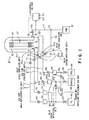
- Fig. 1 is a whole schematic view showing one embodiment of a thermal processing unit according to the present invention.
- a vertical thermal processing unit of this embodiment is provided with a reaction container 2.
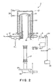
- Fig. 2 is a vertical cross sectional view showing the reaction container 2.
- a reaction tube 21 shown in Fig. 2 is made of, for example, quartz.
- the reaction tube 21 has, for example, a double-tube structure consisting of an inner tube 22 and an outer tube 23.
- the outer tube 23 is provided coaxially with respect to the inner tube 22 so as to form an appropriate space.
- An upper end of the outer tube 23 is closed, and a lower end thereof is airtightly connected to a cylindrical metallic manifold 24.
- an upper end of the inner tube 22 is opened.
- the inner tube 22 is supported by a supporting ring 25 formed to protrude from an inner peripheral face of the manifold 24.
- Wafers W which are objects to be processed are placed on a wafer-boat (supporting member) 27 in a tier-like manner.
- a boat-elevator 26 is adapted to convey the wafer-boat (supporting member) 27 through an opening portion at a lower side of the manifold 24 into the inner tube 22.
- the inner tube 22 forms a thermal processing atmosphere for the wafers W, which are objects to be processed.
- the boat-elevator 26 is provided with a lid 28 capable of closing the opening portion at the lower side of the manifold 24.
- a thermal insulator 29a is arranged so as to surround the circumference of the reaction tube 21.
- a heater 29b composed of, for example, a resistive heating element is provided on an inner wall face of the thermal insulator 29a.
- the thermal insulator 29a and the heater 29b form a heating furnace 29.
- a plurality of gas introducing tubes for convenience, only one of them is shown in the figure) for introducing a process gas, a replacement gas and the like into the reaction container 2 pierce through a lower part of the manifold 24 with respect to the supporting ring 25.
- the gas introducing tubes correspond to gas tubes 5, 6 which are process gas ways and a gas tube 7 which is a replacement gas way.
- a discharging port 30 is formed at a circumferential face of an upper part of the manifold 24 with respect to the supporting ring 25.
- a gas tube 4 for introducing nitrogen gas pierces through an upper part of the manifold 24 with respect to the supporting ring 25.
- a discharging tube 3 serving as a discharging way is hermetically connected to the discharging port 30.
- a vacuum pump 32 is connected to the discharging tube 3 through a pressure-adjusting unit 31.
- the pressure-adjusting unit 31 may be composed of an appropriate unit which adjusts an opening degree of the discharging tube 3.
- a controlling part 100 is adapted to control the pressure-adjusting unit 31, i.e. to adjust the opening degree of the discharging tube 3, depending on a measured pressure obtained by a pressure gauge 101, which measures the pressure inside the reaction container 2. Note that the controlling part 100 conducts not only control of the pressure-adjusting unit 31 but also control of all valves used in this embodiment.
- the gas tubes 5, 6 communicate with their tip portions 50, 60 via valve units 51, 61 provided in a vicinity of the reaction container 2, respectively.
- Each of the tip portions 50, 60 protrudes into the inside of the inner tube 22.
- the valve unit 51 is a combination of a valve 51a which serves as a first open-close unit and a valve 51b which serves as a second open-close unit, as shown in Fig. 1.
- the valve unit 61 is also a combination of a valve 61a which serves as a first open-close unit and a valve 61b which serves as a second open-close unit.
- the valves 51a, 61a are to open and close the gas tubes 5, 6, respectively.
- the valves 51b, 61b are respectively adapted to open and close bypass ways 52, 62, which are branched out from upstream portions with respect to the valves 51a, 61a of the gas tubes 5, 6 and are joined with (connected to) the discharging tube 3.
- the two bypass ways 52, 62 are joined together on their way (before being connected to the discharging tube 3), and are connected at a connection point P1 of the discharging tube 3.
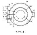
- the gas tube 7 will be described with reference to Fig. 3.
- the gas tube 7 communicates with its tip portion 70 through a valve 71 provided in a vicinity of the reaction container 2.
- the tip portion 70 protrudes into the inside of the inner tube 22.
- valve units 51, 61 and the valve 71 are fixed to, for example, a common fixing member 20 provided in a vicinity of the reaction container 2.
- the reaction container 2 may be provided with a cleaning-gas introducing tube for removing an adhesion which has adhered on the inner wall, and the like, which may also protrude into the inside of the inner tube 22, although they are not shown here.
- the tip of the gas tube 7 is covered with, for example, a ceramic porous layer, which is described in Japanese Patent Laid-Open Publication (Kokai) 2000-58530.
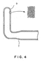
- the ceramic porous layer is, for example, a silica porous layer 9 as shown in Fig. 4. As shown in Fig 4, this silica porous layer 9 has a cylindrical structure whose upper end is closed, and is fixed to the tip of the gas tube 7 by welding.
- a thickness of the silica porous layer 9 is, for example, 10 to 50 mm.
- the gas tube 4 and the gas tube 7 are both provided for supplying the nitrogen gas into the reaction container 2. Therefore, the base sides of the gas tubes 4 and 7 are commonly connected to a nitrogen gas supplying source 4b through a valve 4a.
- a valve 42 and a flow-rate adjusting part 43 are further provided between the valve 4a and the valve 41 in the gas tube 4.
- a valve 72 and a flow-rate adjusting part 73 are also provided between the valve 4a and the valve 71 in the gas tube 7.
- a gas tube 5 is to supply, for example, ammonium (NH 3 ) gas and a gas tube 6 is to supply dichlorosilane (SiH 2 Cl 2 ) gas.
- a base side of the gas tube 5 with respect to the valve unit 51 is connected to a gas supplying source 56 of the ammonium gas thorough a valve 53, a flow-rate adjusting part 54, and a valve 55.
- a base side of the gas tube 6 with respect to the valve unit 61 is connected to a gas supplying source 66 of the dichlorosilane gas thorough a valve 63, a flow-rate adjusting part 64, and a valve 65.
- bypass ways 8a and 8b branched out from between the valve 4a and the flow-rate adjusting part 43 of the gas tube 4, which serve as assistant replacement-gas ways, are respectively connected to the gas tubes 5 and 6. Accordingly, the nitrogen gas may be introduced from the nitrogen gas supplying source 4b to the gas tubes 5 and 6.
- a tip of the bypass way 8a is connected to a point P2 between the flow-rate adjusting part 54 and the valve 55 of the gas tube 5.
- a tip of the bypass way 8b is connected to a point P3 between the flow-rate adjusting part 64 and the valve 65 of the gas tube 6.
- a valve 81 which corresponds to a third open-close unit is provided in the bypass way 8a.
- a valve 82 which corresponds to a third open-close unit is also provided in the bypass way 8b.
- a silicon nitride film is formed.
- 150 sheets of wafers W are placed on the wafer-boat 27 in a tier-like manner.
- This wafer-boat 27 is conveyed by the boat-elevator 26 into the inner tube 22 from the opening portion provided at the lower part of the manifold 24.
- This opening portion is hermetically closed by the lid 28.
- the inside of the reaction tube 21 is heated by the heater 29 to be, for example, about 760 C°.
- a pressure in the reaction tube 21 is adjusted to be, for example, 133 ⁇ 10 -1 Pa (1.0 ⁇ 10 -1 Torr) by adjusting a discharging (exhaust) volume.
- the ammonium gas and the dichlorosilane gas, which are process gases are respectively supplied through the gas tube 5 and the gas tube 6, so that a film-forming process is carried out on the wafers W.
- a gas flow in the film-forming process is shown in Fig. 5.
- a flowing state is indicated with a solid line and a non-flowing state is indicated with a dotted line.
- the process gases flow in the gas tubes 5 and 6.
- the nitrogen gas flows in the gas tube 4 in order to prevent reaction products generated by a reaction of the process gases from adhering to an inner wall of the outer tube 23.
- the nitrogen gas does not flow in the gas tube 7 as shown in Fig. 5 because the valve 72 is closed.
- the nitrogen gas also does not flow at downstream portions of the respective valves 81, 82 of the bypass ways 8a and 8b because the valves 81 and 82 are also closed.
- valves 51b, 61b on the side of the bypass ways in the valve units 51, 61 are closed during the film-forming process for both of the gas tubes 5, 6, in which the gas flows. Accordingly, a sucking force of the vacuum pump 32 reaches only the side of the reaction tube 21.
- the controlling part 100 controls the pressure-adjusting unit 31 in order to maintain the pressure in the reaction container 2 at the aforementioned processing pressure of, for example, 133 ⁇ 10 -1 Pa (1. 0 ⁇ 10 -1 Torr).
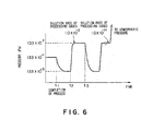
- Fig. 6 is a specific chart showing a pressure change in the reaction container 2 as time passes and a concentration of the remaining process gases (dilution ratio) as well.
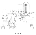
- the valves 55 and 65 are closed so that flow of the process gases into the gas tubes 5, 6 is stopped.
- the valves 51a and 61a are closed, and the pressure-adjusting unit 31 are fully opened (refer to Fig. 7).
- the inside of the reaction container 2 is quickly shifted to a pressure-reduced state.
- the pressure inside the reaction container 2 is maintained to be, for example, 133 ⁇ 10 -3 Pa (1.0 ⁇ 10 -3 Torr).
- the pressure-adjusting unit 31 is once closed and the valve 71 is opened, so that the nitrogen gas introduction from the gas tube 7 is started. Thereafter, while the process gas(es) remaining in the reaction container 2 is replaced with the replacement gas (the discharge from the reaction container 2 is continued), the pressure in the reaction container 2 is raised to be not less than the pressure at the film-forming process.
- This pressure-raising step is carried out aiming that the pressure in the reaction container 2 is raised by introducing the nitrogen gas into the reaction container 2 so that a probability of collision between remaining process gas molecules and nitrogen gas molecules is enhanced. This allows more process gases to be discharged during a pressure-lowering step which is carried out later.
- the nitrogen gas from the gas tube 7 flows into the reaction container 2 at a blast.
- the silica porous layer 9 is provided at a 'gas outlet of the gas tube 7, the nitrogen gas diffuses uniformly and is introduced at a large flow rate without stirring up particles in the reaction container 2.
- the inside pressure of the reaction container 2 is raised to, for example, 133 ⁇ 10 2 Pa, and a dilution ratio of the process gases is, for example, 1.0 ⁇ 10 -2 .
- the pressure-adjusting unit 31 is unfastened at the time t3. Thereby, the inside pressure of the reaction container 2 is lowered to, for example, 133 ⁇ 10 -3 Pa, which is the same as the pressure in the first pressure-lowering step carried out previously. Accordingly, the process gas(es) is discharged together with the nitrogen gas.
- the dilution ratio of the process gas(es) in the reaction container 2 is lowered to be not more than a safety dilution ratio which permits the reaction container 2 to be opened, for example, to be about 1.0 ⁇ 10 -14 .
- the nitrogen gas is introduced from the gas tube 7 to the reaction container 2 with the pressure-adjusting unit 31 being closed, so that the inside of the reaction container 2 is caused back to be at the atmospheric pressure.
- the wafer-boat 27 is lowered.
- a time to maintain this pressure-reduced (lowered) state is, for example, about 5 minutes.
- the dilution ratio of the process gases remaining in the reaction container 2 is lowered to be not more than' the safety dilution ratio, for example, 1.0 ⁇ 10 -14 , and when the inside of the reaction container 2 starts to be caused to get back to the atmospheric pressure, any operation to replace with the nitrogen gas the process gases remaining in the gas tubes 5, 6 for supplying the process gases is started in parallel to that.
- the reaction container 2 for example while the wafer-boat 27 is lowered and/or the wafers W are conveyed out from the wafer-boat 27, the replacement process of the process gases in the gas tubes 5, 6 is carried out concurrently.
- the valve 71 is closed from the state shown in Fig. 7, and the supply of the nitrogen gas to the reaction container 2 is stopped.
- the valve 81 and the valve 82 are opened, and the nitrogen gas is introduced from the bypass ways 8a, 8b to the gas tubes 5, 6.
- the valves 51a, 51b and the valves 61a, 61b are both closed in the valve units 51, 61, and the bypass ways 52, 62 and the gas tubes 5, 6 are not connected (communicated) therebetween. Therefore, pressures in the gas tube 5 and in the gas tube 6 are raised at a blast by the pressure of the nitrogen gas supplied from the upstream side.
- the valves 51a, 61a that are the first open-close units are provided respectively, in the vicinities of the reaction container 2 of the gas tubes 5, 6 for supplying the process gases. Therefore, a room, from which the process gases therein should be discharged, is separated after the completion of the film-forming process, the inside of the reaction container 2 is firstly caused to be in the pressure-reduced state, then the nitrogen gas is introduced from the gas tube 7 into the reaction container 2 so that the inside of the reaction container 2 is caused to be at a pressure higher than that during the thermal process, and thereafter the inside of the reaction container 2 is again caused to be in the pressure-reduced state.
- a time for making the concentration of the process gases in the reaction container not more than the safety standard value after the completion of the thermal process is about 25 minutes in a sequence using the unit shown in Fig. 9 described in the prior art, but about 15 minutes in a sequence in this embodiment.
- the gas replacement process in the gas tubes 5, 6, which are the process gas ways, is carried out while the wafers W are transferred. Therefore, the time of the gas replacement process in the gas tubes 5, 6 does not influence the throughput. Incidentally, it is useful to remove the gases remaining in the gas tubes 5, 6 for carrying out a next thermal process excellently.
- a step may be carried out, in which evacuation is firstly carried out with the valves 51a, 61a being opened after the thermal process, then the valves 51a, 61a are closed and the replacement gas is introduced into the reaction container 2 so that the pressure is raised higher than at the thermal process.
- the double tube structure is used for the reaction container 2 in the above embodiment, but the present invention is also applicable to a unit using a reaction container composed of, for example, a single tube.
Landscapes
- Chemical & Material Sciences (AREA)
- Engineering & Computer Science (AREA)
- Mechanical Engineering (AREA)
- Materials Engineering (AREA)
- General Chemical & Material Sciences (AREA)
- Chemical Kinetics & Catalysis (AREA)
- Metallurgy (AREA)
- Organic Chemistry (AREA)
- General Engineering & Computer Science (AREA)
- Inorganic Chemistry (AREA)
- Chemical Vapour Deposition (AREA)
- Waste-Gas Treatment And Other Accessory Devices For Furnaces (AREA)
- Furnace Details (AREA)
Abstract
Description
Claims (9)
- A thermal processing unit comprising:a reaction container which an object to be processed is conveyed into and from,a process-gas introducing part for introducing a process gas into the reaction container,a replacement-gas introducing part for introducing a replacement gas into the reaction container, the replacement-gas introducing part being independent of the process-gas introducing part,a discharging part for discharging a gas in the reaction container, anda controlling part connected to the process-gas introducing part, the replacement-gas introducing part and the discharging part, the controlling part being adapted to: control the discharging part so as to lower a pressure in the reaction container with respect to at a thermal process; then' control the process-gas introducing part and the replacement-gas introducing part so as to stop introducing the process gas and introduce the replacement gas into' the reaction container as well as control the discharging part so as to raise the pressure in the reaction container with respect to at the thermal process; and then control the discharging part so as to lower the pressure in the reaction container with respect to at the thermal process.
- A thermal processing unit according to claim 1, wherein
the process-gas introducing part has
a process-gas way for introducing the process gas into the reaction container and
a first open-close unit arranged in a vicinity of the reaction container, the first open-close unit opening and closing the process-gas way, and
the controlling part is adapted to control the first open-close unit. - A thermal processing unit according to claim 2, wherein
the discharging part has
a discharging way for discharging the gas in the reaction container and
a pressure-adjusting unit arranged in the discharging way, the pressure-adjusting unit adjusting to open and close the discharging way so as to adjust the pressure in the reaction container, and
the controlling part is adapted to control the pressure-adjusting unit. - A thermal processing unit according to claim 3, further comprising
a bypass way connected between an upstream portion with respect to the first open-close unit in the process-gas way and the discharging way, the bypass way bypassing the reaction container, and
a second open-close unit that opens and closes the bypass way. - A thermal processing unit according to claim 4, wherein
an assistant replacement-gas introducing part for introducing the replacement gas into the processing-gas way is provided at an upstream portion with respect to a position connecting to the bypass way in the process-gas way. - A thermal processing unit according to claim 5, wherein
the assistant replacement-gas introducing part has
an assistant replacement-gas way for introducing the replacement gas into the process-gas way and
a third open-close unit that opens and closes the assistant replacement-gas way. - A thermal processing unit according to claim 6, wherein
the controlling part is connected to the second open-close unit and the third open-close unit, is adapted to control the first open-close unit and the third open-close unit to stop introducing the process gas and to introduce the replacement gas into the process-gas way so as to generate a pressure-raised state in the process-gas way, and then is adapted to control the second open-close unit so as to discharge the gas in the process-gas way through the bypass way. - A thermal processing method for conducting a thermal process to an object to be processed by using a thermal processing unit comprising:a reaction container which an object to be processed is conveyed into and from,a process-gas introducing part for introducing a process gas into the reaction container,a replacement-gas introducing part for introducing a replacement gas into the reaction container, the replacement-gas introducing part being independent of the process-gas introducing part, anda discharging part for discharging a gas in the reaction container,the method comprising:a first pressure-lowering step of controlling the discharging part so as to lower a pressure in the reaction container with respect to at the thermal process, the first pressure-lowering step being conducted after completing the thermal process,a pressure-raising step of controlling the process-gas introducing part and the replacement-gas introducing part so as to stop introducing the process gas and introduce the replacement gas into the reaction container as well as controlling the discharging part so as to raise the pressure in the reaction container with respect to at the thermal process, the pressure-raising step being conducted after the first pressure-lowering step, anda second pressure-lowering step of controlling the discharging part so as to lower the pressure in the reaction container with respect to at the thermal process, the second pressure-lowering step being conducted after the pressure-raising step.
- A thermal processing method for conducting a thermal process to an object to be processed by using a thermal processing unit comprising:a reaction container which an object to be processed is conveyed into and from,a process-gas introducing part for introducing a process gas into the reaction container,a replacement-gas introducing part for introducing a replacement gas into the reaction container, the replacement-gas introducing part being independent of the process-gas introducing part, anda discharging part for discharging a gas in the reaction container,the process-gas introducing part havinga process-gas way for introducing the process gas into the reaction container anda first open-close unit arranged in a vicinity of the reaction container, the first open-close unit opening and closing the process-gas way,the controlling part being adapted to control the first open-close unit,the discharging part havinga discharging way for discharging the gas in the reaction container anda pressure-adjusting unit arranged in the discharging way, the pressure-adjusting unit adjusting to open and close the discharging way so as to adjust the pressure in the reaction container,the controlling part being adapted to control the pressure-adjusting unit,the thermal processing unit further comprisinga bypass way connected between an upstream portion with respect to the first open-close unit in the process-gas way and the discharging way, the bypass way bypassing the reaction container, anda second open-close unit that opens and closes the bypass way,an assistant replacement-gas introducing part for introducing the replacement gas into the processing-gas way being provided at an upstream portion with respect to a position connecting to the bypass way in the process-gas way, andthe assistant replacement-gas introducing part havingan assistant replacement-gas way for introducing the replacement gas into the process-gas way anda third open-close unit that opens and closes the assistant replacement-gas way,the method comprising:a pressure-raising step of controlling the first open-close unit and the third open-close unit so as to stop introducing the process gas and introduce the replacement gas into the process-gas way so as to generate a pressure-raised state in the process-gas way, anda step of controlling the second open-close unit to discharge the gas in the process-gas way through the bypass way, the step being conducted after the pressure-raising step.
Priority Applications (1)
| Application Number | Priority Date | Filing Date | Title |
|---|---|---|---|
| EP06000518A EP1657741A1 (en) | 2001-03-30 | 2002-03-13 | Thermal processing unit and thermal processing method |
Applications Claiming Priority (3)
| Application Number | Priority Date | Filing Date | Title |
|---|---|---|---|
| JP2001098044A JP3403181B2 (en) | 2001-03-30 | 2001-03-30 | Heat treatment apparatus and heat treatment method |
| JP2001098044 | 2001-03-30 | ||
| PCT/JP2002/002377 WO2002082523A1 (en) | 2001-03-30 | 2002-03-13 | Heat treating method and heat treating device |
Related Child Applications (1)
| Application Number | Title | Priority Date | Filing Date |
|---|---|---|---|
| EP06000518A Division EP1657741A1 (en) | 2001-03-30 | 2002-03-13 | Thermal processing unit and thermal processing method |
Publications (3)
| Publication Number | Publication Date |
|---|---|
| EP1381079A1 true EP1381079A1 (en) | 2004-01-14 |
| EP1381079A4 EP1381079A4 (en) | 2005-06-29 |
| EP1381079B1 EP1381079B1 (en) | 2007-01-03 |
Family
ID=18951740
Family Applications (2)
| Application Number | Title | Priority Date | Filing Date |
|---|---|---|---|
| EP06000518A Withdrawn EP1657741A1 (en) | 2001-03-30 | 2002-03-13 | Thermal processing unit and thermal processing method |
| EP02705146A Expired - Lifetime EP1381079B1 (en) | 2001-03-30 | 2002-03-13 | Heat treating method |
Family Applications Before (1)
| Application Number | Title | Priority Date | Filing Date |
|---|---|---|---|
| EP06000518A Withdrawn EP1657741A1 (en) | 2001-03-30 | 2002-03-13 | Thermal processing unit and thermal processing method |
Country Status (7)
| Country | Link |
|---|---|
| US (1) | US6814572B2 (en) |
| EP (2) | EP1657741A1 (en) |
| JP (1) | JP3403181B2 (en) |
| KR (1) | KR100590131B1 (en) |
| CN (1) | CN1215538C (en) |
| DE (1) | DE60217317T8 (en) |
| WO (1) | WO2002082523A1 (en) |
Families Citing this family (28)
| Publication number | Priority date | Publication date | Assignee | Title |
|---|---|---|---|---|
| JP4074461B2 (en) * | 2002-02-06 | 2008-04-09 | 東京エレクトロン株式会社 | Film forming method, film forming apparatus, and semiconductor device manufacturing method |
| JP3985899B2 (en) * | 2002-03-28 | 2007-10-03 | 株式会社日立国際電気 | Substrate processing equipment |
| JP4421393B2 (en) * | 2004-06-22 | 2010-02-24 | 東京エレクトロン株式会社 | Substrate processing equipment |
| US20050287806A1 (en) * | 2004-06-24 | 2005-12-29 | Hiroyuki Matsuura | Vertical CVD apparatus and CVD method using the same |
| KR100609065B1 (en) * | 2004-08-04 | 2006-08-10 | 삼성전자주식회사 | Oxide film forming apparatus and method |
| US7425692B2 (en) * | 2004-09-07 | 2008-09-16 | Btu International, Inc. | Thermal processing system having slot eductors |
| US7966969B2 (en) * | 2004-09-22 | 2011-06-28 | Asm International N.V. | Deposition of TiN films in a batch reactor |
| US20060156980A1 (en) * | 2005-01-19 | 2006-07-20 | Samsung Electronics Co., Ltd. | Apparatus including 4-way valve for fabricating semiconductor device, method of controlling valve, and method of fabricating semiconductor device using the apparatus |
| JP4506677B2 (en) * | 2005-03-11 | 2010-07-21 | 東京エレクトロン株式会社 | Film forming method, film forming apparatus, and storage medium |
| JP4698354B2 (en) * | 2005-09-15 | 2011-06-08 | 株式会社リコー | CVD equipment |
| US7691757B2 (en) | 2006-06-22 | 2010-04-06 | Asm International N.V. | Deposition of complex nitride films |
| JP4273145B2 (en) * | 2006-09-13 | 2009-06-03 | エスペック株式会社 | Heat treatment equipment |
| KR100872312B1 (en) * | 2007-05-04 | 2008-12-05 | 주식회사 디엠에스 | Etching Gas Control System |
| US7629256B2 (en) | 2007-05-14 | 2009-12-08 | Asm International N.V. | In situ silicon and titanium nitride deposition |
| US20090197424A1 (en) * | 2008-01-31 | 2009-08-06 | Hitachi Kokusai Electric Inc. | Substrate processing apparatus and method for manufacturing semiconductor device |
| US20090212014A1 (en) * | 2008-02-27 | 2009-08-27 | Tokyo Electron Limited | Method and system for performing multiple treatments in a dual-chamber batch processing system |
| US7833906B2 (en) | 2008-12-11 | 2010-11-16 | Asm International N.V. | Titanium silicon nitride deposition |
| JP5966649B2 (en) * | 2012-06-18 | 2016-08-10 | 東京エレクトロン株式会社 | Heat treatment equipment |
| US20140038421A1 (en) * | 2012-08-01 | 2014-02-06 | Taiwan Semiconductor Manufacturing Company, Ltd. | Deposition Chamber and Injector |
| JP6020227B2 (en) * | 2013-02-12 | 2016-11-02 | 東京エレクトロン株式会社 | Gas supply system and film forming apparatus |
| KR20160026572A (en) * | 2014-09-01 | 2016-03-09 | 삼성전자주식회사 | Apparatus for processing a substrate |
| JP6486160B2 (en) | 2015-03-23 | 2019-03-20 | 東京エレクトロン株式会社 | Heat treatment equipment |
| JP2018186235A (en) * | 2017-04-27 | 2018-11-22 | 東京エレクトロン株式会社 | Substrate processing apparatus, particle removal method in injector and substrate processing method |
| US11393703B2 (en) * | 2018-06-18 | 2022-07-19 | Applied Materials, Inc. | Apparatus and method for controlling a flow process material to a deposition chamber |
| JP7027565B2 (en) * | 2018-09-11 | 2022-03-01 | 株式会社Kokusai Electric | Substrate processing equipment, semiconductor equipment manufacturing methods and programs |
| JP6651591B1 (en) * | 2018-09-27 | 2020-02-19 | 株式会社Kokusai Electric | Substrate processing apparatus and semiconductor device manufacturing method |
| JP7487084B2 (en) * | 2020-12-07 | 2024-05-20 | 株式会社Screenホールディングス | Heat Treatment Equipment |
| JP7687791B2 (en) | 2021-03-15 | 2025-06-03 | 東京エレクトロン株式会社 | Temperature control unit and processing device |
Family Cites Families (8)
| Publication number | Priority date | Publication date | Assignee | Title |
|---|---|---|---|---|
| US4369031A (en) * | 1981-09-15 | 1983-01-18 | Thermco Products Corporation | Gas control system for chemical vapor deposition system |
| US5484484A (en) * | 1993-07-03 | 1996-01-16 | Tokyo Electron Kabushiki | Thermal processing method and apparatus therefor |
| JPH0774104A (en) * | 1993-08-31 | 1995-03-17 | Sony Corp | Reactor |
| US5920797A (en) * | 1996-12-03 | 1999-07-06 | Applied Materials, Inc. | Method for gaseous substrate support |
| KR100505310B1 (en) * | 1998-05-13 | 2005-08-04 | 동경 엘렉트론 주식회사 | Single-substrate-processing cvd apparatus and method |
| KR100282853B1 (en) * | 1998-05-18 | 2001-04-02 | 서성기 | Apparatus for thin film deposition using cyclic gas injection |
| JP3396431B2 (en) | 1998-08-10 | 2003-04-14 | 東京エレクトロン株式会社 | Oxidation treatment method and oxidation treatment device |
| US6645302B2 (en) * | 2000-04-26 | 2003-11-11 | Showa Denko Kabushiki Kaisha | Vapor phase deposition system |
-
2001
- 2001-03-30 JP JP2001098044A patent/JP3403181B2/en not_active Expired - Fee Related
-
2002
- 2002-03-13 EP EP06000518A patent/EP1657741A1/en not_active Withdrawn
- 2002-03-13 US US10/473,249 patent/US6814572B2/en not_active Expired - Lifetime
- 2002-03-13 EP EP02705146A patent/EP1381079B1/en not_active Expired - Lifetime
- 2002-03-13 WO PCT/JP2002/002377 patent/WO2002082523A1/en not_active Ceased
- 2002-03-13 DE DE60217317T patent/DE60217317T8/en active Active
- 2002-03-13 KR KR1020037011124A patent/KR100590131B1/en not_active Expired - Fee Related
- 2002-03-13 CN CNB028057635A patent/CN1215538C/en not_active Expired - Fee Related
Also Published As
| Publication number | Publication date |
|---|---|
| EP1381079B1 (en) | 2007-01-03 |
| DE60217317T2 (en) | 2007-07-05 |
| KR20030082605A (en) | 2003-10-22 |
| DE60217317D1 (en) | 2007-02-15 |
| KR100590131B1 (en) | 2006-06-15 |
| JP2002299327A (en) | 2002-10-11 |
| CN1215538C (en) | 2005-08-17 |
| CN1496582A (en) | 2004-05-12 |
| EP1381079A4 (en) | 2005-06-29 |
| US6814572B2 (en) | 2004-11-09 |
| JP3403181B2 (en) | 2003-05-06 |
| WO2002082523A1 (en) | 2002-10-17 |
| US20040115584A1 (en) | 2004-06-17 |
| DE60217317T8 (en) | 2007-10-04 |
| EP1657741A1 (en) | 2006-05-17 |
Similar Documents
| Publication | Publication Date | Title |
|---|---|---|
| EP1381079B1 (en) | Heat treating method | |
| CN104681466B (en) | Substrate processing apparatus and method for manufacturing semiconductor device | |
| US20080087218A1 (en) | Board processing apparatus and method of fabricating semiconductor apparatus | |
| US20100022093A1 (en) | Vacuum processing apparatus, method of operating same and storage medium | |
| TWI415206B (en) | A substrate processing apparatus, and a method of manufacturing the semiconductor device | |
| CN1742113B (en) | Vacuum treatment device | |
| CN112349623B (en) | Substrate processing apparatus, method for manufacturing semiconductor device, and computer-readable recording medium | |
| TW201826355A (en) | Film forming apparatus and film forming method | |
| US20040007186A1 (en) | Heat-treating device | |
| KR101210458B1 (en) | Method of manufacturing semiconductor device and substrate processing apparatus | |
| US6287984B1 (en) | Apparatus and method for manufacturing semiconductor device | |
| KR20150120470A (en) | Substrate processing device, method for manufacturing semiconductor device, and method for processing substrate | |
| KR20210018075A (en) | Substrate processing apparatus, method of manufacturing semiconductor device and substrate processing program | |
| JP2006032610A (en) | Deposition equipment | |
| EP1357582A1 (en) | Heat-treating device | |
| JPH04162709A (en) | Manufacturing apparatus of semiconductor and processing method of reaction | |
| JPH0387386A (en) | Substrate treating device | |
| JP2000306838A (en) | Treatment method and apparatus for semiconductor substrate | |
| JPH10154702A (en) | Semiconductor manufacturing method and apparatus | |
| JPH02122076A (en) | Film forming method | |
| JP3670524B2 (en) | Manufacturing method of semiconductor device | |
| JP2012136743A (en) | Substrate treatment device | |
| JP2006086186A (en) | Substrate processing equipment | |
| JP4597393B2 (en) | Heat treatment equipment | |
| JP2011222656A (en) | Substrate treatment apparatus |
Legal Events
| Date | Code | Title | Description |
|---|---|---|---|
| PUAI | Public reference made under article 153(3) epc to a published international application that has entered the european phase |
Free format text: ORIGINAL CODE: 0009012 |
|
| 17P | Request for examination filed |
Effective date: 20030930 |
|
| AK | Designated contracting states |
Kind code of ref document: A1 Designated state(s): AT BE CH CY DE DK ES FI FR GB GR IE IT LI LU MC NL PT SE TR |
|
| RIN1 | Information on inventor provided before grant (corrected) |
Inventor name: OKABE, TSUNEYUKI,TOKYO ELECTRON LTD. |
|
| A4 | Supplementary search report drawn up and despatched |
Effective date: 20050518 |
|
| RBV | Designated contracting states (corrected) |
Designated state(s): DE FR GB IT NL |
|
| GRAP | Despatch of communication of intention to grant a patent |
Free format text: ORIGINAL CODE: EPIDOSNIGR1 |
|
| RTI1 | Title (correction) |
Free format text: HEAT TREATING METHOD |
|
| GRAS | Grant fee paid |
Free format text: ORIGINAL CODE: EPIDOSNIGR3 |
|
| GRAA | (expected) grant |
Free format text: ORIGINAL CODE: 0009210 |
|
| RIN1 | Information on inventor provided before grant (corrected) |
Inventor name: OKABE, TSUNEYUKI,TOKYO ELECTRON LTD. |
|
| AK | Designated contracting states |
Kind code of ref document: B1 Designated state(s): DE FR GB IT NL |
|
| REG | Reference to a national code |
Ref country code: GB Ref legal event code: FG4D |
|
| REF | Corresponds to: |
Ref document number: 60217317 Country of ref document: DE Date of ref document: 20070215 Kind code of ref document: P |
|
| ET | Fr: translation filed | ||
| PLBE | No opposition filed within time limit |
Free format text: ORIGINAL CODE: 0009261 |
|
| STAA | Information on the status of an ep patent application or granted ep patent |
Free format text: STATUS: NO OPPOSITION FILED WITHIN TIME LIMIT |
|
| 26N | No opposition filed |
Effective date: 20071005 |
|
| GBPC | Gb: european patent ceased through non-payment of renewal fee |
Effective date: 20070403 |
|
| PG25 | Lapsed in a contracting state [announced via postgrant information from national office to epo] |
Ref country code: GB Free format text: LAPSE BECAUSE OF NON-PAYMENT OF DUE FEES Effective date: 20070403 |
|
| REG | Reference to a national code |
Ref country code: FR Ref legal event code: PLFP Year of fee payment: 14 |
|
| PGFP | Annual fee paid to national office [announced via postgrant information from national office to epo] |
Ref country code: NL Payment date: 20150210 Year of fee payment: 14 |
|
| PGFP | Annual fee paid to national office [announced via postgrant information from national office to epo] |
Ref country code: IT Payment date: 20150223 Year of fee payment: 14 Ref country code: DE Payment date: 20150310 Year of fee payment: 14 |
|
| PGFP | Annual fee paid to national office [announced via postgrant information from national office to epo] |
Ref country code: FR Payment date: 20150309 Year of fee payment: 14 |
|
| REG | Reference to a national code |
Ref country code: DE Ref legal event code: R119 Ref document number: 60217317 Country of ref document: DE |
|
| REG | Reference to a national code |
Ref country code: NL Ref legal event code: MM Effective date: 20160401 |
|
| REG | Reference to a national code |
Ref country code: FR Ref legal event code: ST Effective date: 20161130 |
|
| PG25 | Lapsed in a contracting state [announced via postgrant information from national office to epo] |
Ref country code: DE Free format text: LAPSE BECAUSE OF NON-PAYMENT OF DUE FEES Effective date: 20161001 Ref country code: FR Free format text: LAPSE BECAUSE OF NON-PAYMENT OF DUE FEES Effective date: 20160331 Ref country code: NL Free format text: LAPSE BECAUSE OF NON-PAYMENT OF DUE FEES Effective date: 20160401 |
|
| PG25 | Lapsed in a contracting state [announced via postgrant information from national office to epo] |
Ref country code: IT Free format text: LAPSE BECAUSE OF NON-PAYMENT OF DUE FEES Effective date: 20160313 |