EP1381069A2 - Bicycle power supply with full-wave and half-wave charging elements - Google Patents
Bicycle power supply with full-wave and half-wave charging elements Download PDFInfo
- Publication number
- EP1381069A2 EP1381069A2 EP03015784A EP03015784A EP1381069A2 EP 1381069 A2 EP1381069 A2 EP 1381069A2 EP 03015784 A EP03015784 A EP 03015784A EP 03015784 A EP03015784 A EP 03015784A EP 1381069 A2 EP1381069 A2 EP 1381069A2
- Authority
- EP
- European Patent Office
- Prior art keywords
- wave
- dynamo
- full
- charging element
- charging
- Prior art date
- Legal status (The legal status is an assumption and is not a legal conclusion. Google has not performed a legal analysis and makes no representation as to the accuracy of the status listed.)
- Granted
Links
Images
Classifications
-
- H—ELECTRICITY
- H02—GENERATION; CONVERSION OR DISTRIBUTION OF ELECTRIC POWER
- H02J—ELECTRIC POWER NETWORKS; CIRCUIT ARRANGEMENTS OR SYSTEMS FOR SUPPLYING OR DISTRIBUTING ELECTRIC POWER; SYSTEMS FOR STORING ELECTRIC ENERGY
- H02J7/00—Circuit arrangements for charging or discharging batteries or for supplying loads from batteries
- H02J7/14—Circuit arrangements for charging or discharging batteries or for supplying loads from batteries for charging batteries from dynamo-electric generators driven at varying speed, e.g. on vehicle
- H02J7/1407—Circuit arrangements for charging or discharging batteries or for supplying loads from batteries for charging batteries from dynamo-electric generators driven at varying speed, e.g. on vehicle on vehicles not being driven by a motor, e.g. bicycles
-
- H—ELECTRICITY
- H02—GENERATION; CONVERSION OR DISTRIBUTION OF ELECTRIC POWER
- H02M—APPARATUS FOR CONVERSION BETWEEN AC AND AC, BETWEEN AC AND DC, OR BETWEEN DC AND DC, AND FOR USE WITH MAINS OR SIMILAR POWER SUPPLY SYSTEMS; CONVERSION OF DC OR AC INPUT POWER INTO SURGE OUTPUT POWER; CONTROL OR REGULATION THEREOF
- H02M7/00—Conversion of AC power input into DC power output; Conversion of DC power input into AC power output
- H02M7/02—Conversion of AC power input into DC power output without possibility of reversal
- H02M7/04—Conversion of AC power input into DC power output without possibility of reversal by static converters
- H02M7/06—Conversion of AC power input into DC power output without possibility of reversal by static converters using discharge tubes without control electrode or semiconductor devices without control electrode
- H02M7/10—Conversion of AC power input into DC power output without possibility of reversal by static converters using discharge tubes without control electrode or semiconductor devices without control electrode arranged for operation in series, e.g. for multiplication of voltage
Definitions
- the present invention is directed to bicycles and, more particularly, to a charging apparatus that charges with voltage from an alternating current bicycle dynamo.
- Automatic transmission shifting devices are commonly provided in newer bicycles. Such bicycles often employ an electrically powered transmission. Accordingly, a dynamo is usually provided for generating electrical power, and a charging system is provided for charging a battery or other voltage storing device used to supply the electrical power to the electrically powered transmission. Since the dynamo generates an alternating current voltage, and since electrically powered transmissions often operate using direct current voltages, half-wave or full-wave rectification of the dynamo output signal usually must be performed.
- a charging apparatus comprises a rectifying circuit for rectifying the alternating current from the bicycle dynamo; a full-wave charging element operatively coupled to the rectifying circuit for charging during both positive and negative half-cycles of the bicycle dynamo; a first half-wave charging element operatively coupled to the rectifying circuit in parallel with the full-wave charging element, wherein the first half-wave charging element charges during positive half-cycles of said dynamo; and a second half-wave charging element operatively coupled to the rectifying circuit in parallel with the full-wave charging element, wherein the second half-wave charging element charges during negative half-cycles of the dynamo. Additional inventive features will become apparent from the description below, and such features alone or in combination with the above features may form the basis of further inventions as recited in the claims and their equivalents.
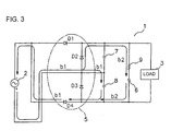
- Fig. 1 is a schematic diagram of a particular embodiment of a charging apparatus 1 that charges with voltage from an alternating current bicycle dynamo 2, wherein charging apparatus 1 is connected between dynamo 2 and a load 3.
- Charging apparatus 1 comprises a full-wave rectifier circuit 5, a full-wave charging element comprising an electric double layer capacitor 6 (which is environmentally friendly), and first and second half-wave charging elements comprising first and second electrolytic capacitors 7 and 8.
- a resistance 9 is connected in series with electric double layer capacitor 6.
- full-wave rectifier circuit 5 is a bridge rectifier circuit comprising four connected diodes D1, D2, D3, D4.
- Electric double layer capacitor 6 is connected to the output of full-wave rectifier circuit 5 such that full-wave rectifier circuit 5 charges electric double layer capacitor 6 during the entire sinusoidal cycle of dynamo 2.
- First and second electrolytic capacitors 7 and 8 are connected in parallel with electric double layer capacitor 6. More specifically, one end of first electrolytic capacitor 7 and the terminal of resistor 9 opposite electric double layer capacitor 6 are connected to a node between diode D1 and diode D2 of full-wave rectifier circuit 5, and at the other end of first electrolytic capacitor 7 is connected to a node between diode D2 and diode D3.
- second electrolytic capacitor 8 One end of second electrolytic capacitor 8 is connected to the node between diode D2 and diode D3, and the other end of second electrolytic capacitor 8 together with the terminal of electric double layer capacitor 6 opposite resistor 9 are connected to a node between diode D3 and diode D4.
- Capacitors 6, 7, and 8 are repeatedly charged by the above-described operation. Electric double layer capacitor 8 is charged to voltage that is double the peak value of the maximum dynamo voltage, thus eliminating the problem of insufficient voltage at low speed (i.e., during low dynamo rotation speed). Additionally, the first and second electrolytic capacitors 7 and 8 are relatively inexpensive, so increased cost of the devices can be avoided.
Landscapes
- Engineering & Computer Science (AREA)
- Power Engineering (AREA)
- Charge And Discharge Circuits For Batteries Or The Like (AREA)
- Control Of Charge By Means Of Generators (AREA)
- Secondary Cells (AREA)
- Electric Propulsion And Braking For Vehicles (AREA)
Abstract
Description
Claims (7)
- A charging apparatus (1) that charges with voltage from an alternating current bicycle dynamo (2), wherein the charging apparatus (1) comprises:a rectifying circuit (5) for rectifying the alternating current from the bicycle dynamo (2);a full-wave charging element (6) operatively coupled to the rectifying circuit (5) for charging during both positive and negative half-cycles of the bicycle dynamo (2);a first half-wave charging element (7) operatively coupled to the rectifying circuit (5) in parallel with the full-wave charging element (6), wherein the first half-wave charging element (7) charges during positive half-cycles of said dynamo (2); anda second half-wave charging element (8) operatively coupled to the rectifying circuit (5) in parallel with the full-wave charging element (6), wherein the second half-wave charging element (7) charges during negative half-cycles of the dynamo (2).
- The charging apparatus according to claim 1 wherein the full-wave charging element (6) comprises a secondary cell.
- The charging apparatus according to claim 1 wherein the first half-wave charging element (7) is connected in series with the second half-wave charging element (8).
- The charging apparatus according to claim 1 wherein the full-wave charging element (6) comprises an electric double layer capacitor.
- The charging apparatus according to claims 1 or 4 wherein the first half-wave charging element (7) comprises a first electrolytic capacitor.
- The charging apparatus according to claim 5 wherein the second half-wave charging element (8) comprises a second electrolytic capacitor.
- The charging apparatus according to claim 6 wherein the first electrolytic capacitor is connected in series with the second electrolytic capacitor.
Applications Claiming Priority (2)
| Application Number | Priority Date | Filing Date | Title |
|---|---|---|---|
| JP2002202501 | 2002-07-11 | ||
| JP2002202501A JP2004048897A (en) | 2002-07-11 | 2002-07-11 | Charger of bicycle dynamo |
Publications (3)
| Publication Number | Publication Date |
|---|---|
| EP1381069A2 true EP1381069A2 (en) | 2004-01-14 |
| EP1381069A3 EP1381069A3 (en) | 2007-10-03 |
| EP1381069B1 EP1381069B1 (en) | 2012-01-18 |
Family
ID=29728498
Family Applications (1)
| Application Number | Title | Priority Date | Filing Date |
|---|---|---|---|
| EP03015784A Expired - Lifetime EP1381069B1 (en) | 2002-07-11 | 2003-07-10 | Bicycle power supply with full-wave and half-wave charging elements |
Country Status (5)
| Country | Link |
|---|---|
| US (1) | US20040051506A1 (en) |
| EP (1) | EP1381069B1 (en) |
| JP (1) | JP2004048897A (en) |
| CN (1) | CN1471213A (en) |
| TW (1) | TWI221694B (en) |
Cited By (2)
| Publication number | Priority date | Publication date | Assignee | Title |
|---|---|---|---|---|
| WO2011000974A3 (en) * | 2010-10-19 | 2011-08-25 | Phonak Ag | Hearing instrument comprising a rechargeable power source |
| US8569973B2 (en) | 2009-12-23 | 2013-10-29 | Dora S.P.A. | Power supply for lamps, particularly for LED-MR16 lamps |
Families Citing this family (6)
| Publication number | Priority date | Publication date | Assignee | Title |
|---|---|---|---|---|
| JP3645881B2 (en) * | 2002-10-18 | 2005-05-11 | 株式会社シマノ | Bicycle dynamo charger |
| TWI386133B (en) | 2009-10-05 | 2013-02-11 | Taiwan Textile Res Inst | Assembled flexible textile capacitor module |
| CN102431488B (en) * | 2011-12-16 | 2014-07-30 | 庄景阳 | Headlamp signal control rectifier current output device |
| CN102386669A (en) * | 2011-12-16 | 2012-03-21 | 庄景阳 | Device for improving charging current of rectifier by means of energy storage capacitor |
| JP2016201973A (en) * | 2015-04-14 | 2016-12-01 | ミツミ電機株式会社 | Full-wave voltage doubler rectifier circuit and power supply device |
| CN108736750B (en) * | 2018-06-11 | 2024-10-01 | 重庆和诚电器有限公司 | Half-wave voltage regulator for motorcycle magneto |
Family Cites Families (6)
| Publication number | Priority date | Publication date | Assignee | Title |
|---|---|---|---|---|
| DE3933391A1 (en) * | 1989-10-06 | 1991-04-18 | Sen Gerhard Stahlmann | Lighting amplifier for powered bicycle or low power motorcycle - uses generator coupled to electrolytic capacitor circuit to provide output |
| DK0460585T3 (en) * | 1990-06-07 | 1994-03-07 | Bisy Bike Systems Ind Fertigun | Bicycle light system with alternator |
| DE4222994C2 (en) * | 1992-07-13 | 1994-12-22 | Busch & Mueller Fahrzeugteile | Lighting device, in particular for bicycle rear lights, and method for its operation with optimal use of the power of a small generator (bicycle dynamo) |
| GB9314262D0 (en) * | 1993-07-09 | 1993-08-18 | Sgs Thomson Microelectronics | A multistandard ac/dc converter embodying mains voltage detection |
| JP3396655B2 (en) * | 2000-02-29 | 2003-04-14 | 株式会社シマノ | Bicycle power supply |
| JP3679681B2 (en) * | 2000-04-05 | 2005-08-03 | ペンタックス株式会社 | Power supply device and electric double layer capacitor charging method |
-
2002
- 2002-07-11 JP JP2002202501A patent/JP2004048897A/en active Pending
-
2003
- 2003-06-09 TW TW092115563A patent/TWI221694B/en not_active IP Right Cessation
- 2003-07-08 US US10/616,252 patent/US20040051506A1/en not_active Abandoned
- 2003-07-10 CN CNA031472451A patent/CN1471213A/en active Pending
- 2003-07-10 EP EP03015784A patent/EP1381069B1/en not_active Expired - Lifetime
Cited By (2)
| Publication number | Priority date | Publication date | Assignee | Title |
|---|---|---|---|---|
| US8569973B2 (en) | 2009-12-23 | 2013-10-29 | Dora S.P.A. | Power supply for lamps, particularly for LED-MR16 lamps |
| WO2011000974A3 (en) * | 2010-10-19 | 2011-08-25 | Phonak Ag | Hearing instrument comprising a rechargeable power source |
Also Published As
| Publication number | Publication date |
|---|---|
| JP2004048897A (en) | 2004-02-12 |
| CN1471213A (en) | 2004-01-28 |
| US20040051506A1 (en) | 2004-03-18 |
| TWI221694B (en) | 2004-10-01 |
| EP1381069B1 (en) | 2012-01-18 |
| EP1381069A3 (en) | 2007-10-03 |
| TW200401489A (en) | 2004-01-16 |
Similar Documents
| Publication | Publication Date | Title |
|---|---|---|
| TW483214B (en) | Charging device and charging method thereof | |
| KR900700934A (en) | Electronic wrist watch with power generation device | |
| JP6519574B2 (en) | Wireless power receiving device, wireless power transmission device using the same, and rectifier | |
| JP2013258883A (en) | Power conversion device | |
| EP1381069A2 (en) | Bicycle power supply with full-wave and half-wave charging elements | |
| JP2010022133A (en) | Charger device | |
| JP3645881B2 (en) | Bicycle dynamo charger | |
| JP2014171313A (en) | Dc/dc converter | |
| JP2007209056A (en) | Power storage device | |
| CN203617920U (en) | Voltage doubling rectifying circuit used for power source | |
| JP2008064539A (en) | Electronic ammeter | |
| TWI422114B (en) | A self powered feed forward charging circuit and design methodology for the protection of electrical energy storage devices | |
| JP2010148302A (en) | Dc/dc power converter | |
| JP3656779B2 (en) | DC-DC converter | |
| US9966792B2 (en) | Uninterruptible power supply for SMPS loads | |
| CN205986691U (en) | Start difunctional circuit of drive / rectification that power generating equipment used | |
| JP2001211650A (en) | Power supply | |
| WO2015114780A1 (en) | Capacitor input smoothing circuit | |
| CN108336806A (en) | A kind of comprehensive power supply device and method | |
| JP3551324B2 (en) | Point load type electrical equipment | |
| JP2009290970A (en) | Power supply system | |
| EP2068421A3 (en) | Voltage regulator and generator assembly for charging batteries | |
| JPH06245541A (en) | Inverter control power supply method | |
| JP4522157B2 (en) | Battery charging device and power supply device | |
| JPH1032981A (en) | Power supply |
Legal Events
| Date | Code | Title | Description |
|---|---|---|---|
| PUAI | Public reference made under article 153(3) epc to a published international application that has entered the european phase |
Free format text: ORIGINAL CODE: 0009012 |
|
| AK | Designated contracting states |
Kind code of ref document: A2 Designated state(s): AT BE BG CH CY CZ DE DK EE ES FI FR GB GR HU IE IT LI LU MC NL PT RO SE SI SK TR |
|
| AX | Request for extension of the european patent |
Extension state: AL LT LV MK |
|
| RAP1 | Party data changed (applicant data changed or rights of an application transferred) |
Owner name: SHIMANO INC. |
|
| PUAL | Search report despatched |
Free format text: ORIGINAL CODE: 0009013 |
|
| AK | Designated contracting states |
Kind code of ref document: A3 Designated state(s): AT BE BG CH CY CZ DE DK EE ES FI FR GB GR HU IE IT LI LU MC NL PT RO SE SI SK TR |
|
| AX | Request for extension of the european patent |
Extension state: AL LT LV MK |
|
| RIC1 | Information provided on ipc code assigned before grant |
Ipc: B62J 6/00 20060101ALI20070827BHEP Ipc: H01J 7/14 20060101AFI20031028BHEP |
|
| 17P | Request for examination filed |
Effective date: 20071017 |
|
| AKX | Designation fees paid |
Designated state(s): DE NL |
|
| 17Q | First examination report despatched |
Effective date: 20090908 |
|
| REG | Reference to a national code |
Ref country code: DE Ref legal event code: R079 Ref document number: 60339734 Country of ref document: DE Free format text: PREVIOUS MAIN CLASS: H01J0007140000 Ipc: H02J0007140000 |
|
| GRAP | Despatch of communication of intention to grant a patent |
Free format text: ORIGINAL CODE: EPIDOSNIGR1 |
|
| RIC1 | Information provided on ipc code assigned before grant |
Ipc: H02J 7/14 20060101AFI20111010BHEP Ipc: B62J 6/00 20060101ALI20111010BHEP |
|
| RIN1 | Information on inventor provided before grant (corrected) |
Inventor name: KITAMURA, SATOSHI |
|
| GRAS | Grant fee paid |
Free format text: ORIGINAL CODE: EPIDOSNIGR3 |
|
| GRAA | (expected) grant |
Free format text: ORIGINAL CODE: 0009210 |
|
| AK | Designated contracting states |
Kind code of ref document: B1 Designated state(s): DE NL |
|
| REG | Reference to a national code |
Ref country code: DE Ref legal event code: R096 Ref document number: 60339734 Country of ref document: DE Effective date: 20120315 |
|
| REG | Reference to a national code |
Ref country code: NL Ref legal event code: T3 |
|
| PLBE | No opposition filed within time limit |
Free format text: ORIGINAL CODE: 0009261 |
|
| STAA | Information on the status of an ep patent application or granted ep patent |
Free format text: STATUS: NO OPPOSITION FILED WITHIN TIME LIMIT |
|
| 26N | No opposition filed |
Effective date: 20121019 |
|
| REG | Reference to a national code |
Ref country code: DE Ref legal event code: R097 Ref document number: 60339734 Country of ref document: DE Effective date: 20121019 |
|
| PGFP | Annual fee paid to national office [announced via postgrant information from national office to epo] |
Ref country code: NL Payment date: 20160610 Year of fee payment: 14 |
|
| REG | Reference to a national code |
Ref country code: NL Ref legal event code: MM Effective date: 20170801 |
|
| PG25 | Lapsed in a contracting state [announced via postgrant information from national office to epo] |
Ref country code: NL Free format text: LAPSE BECAUSE OF NON-PAYMENT OF DUE FEES Effective date: 20170801 |
|
| PGFP | Annual fee paid to national office [announced via postgrant information from national office to epo] |
Ref country code: DE Payment date: 20180626 Year of fee payment: 16 |
|
| REG | Reference to a national code |
Ref country code: DE Ref legal event code: R119 Ref document number: 60339734 Country of ref document: DE |
|
| PG25 | Lapsed in a contracting state [announced via postgrant information from national office to epo] |
Ref country code: DE Free format text: LAPSE BECAUSE OF NON-PAYMENT OF DUE FEES Effective date: 20200201 |