EP1380807B1 - Befestigungseinrichtung für ein Zielfernrohr an einer Waffe - Google Patents
Befestigungseinrichtung für ein Zielfernrohr an einer Waffe Download PDFInfo
- Publication number
- EP1380807B1 EP1380807B1 EP02015263A EP02015263A EP1380807B1 EP 1380807 B1 EP1380807 B1 EP 1380807B1 EP 02015263 A EP02015263 A EP 02015263A EP 02015263 A EP02015263 A EP 02015263A EP 1380807 B1 EP1380807 B1 EP 1380807B1
- Authority
- EP
- European Patent Office
- Prior art keywords
- mounting
- fastening device
- opening
- rail
- mounting apparatus
- Prior art date
- Legal status (The legal status is an assumption and is not a legal conclusion. Google has not performed a legal analysis and makes no representation as to the accuracy of the status listed.)
- Expired - Lifetime
Links
- 230000000284 resting effect Effects 0.000 abstract 1
- 239000000463 material Substances 0.000 description 2
- 229910000831 Steel Inorganic materials 0.000 description 1
- XAGFODPZIPBFFR-UHFFFAOYSA-N aluminium Chemical compound [Al] XAGFODPZIPBFFR-UHFFFAOYSA-N 0.000 description 1
- 229910052782 aluminium Inorganic materials 0.000 description 1
- 230000004323 axial length Effects 0.000 description 1
- 238000011109 contamination Methods 0.000 description 1
- 238000010304 firing Methods 0.000 description 1
- 238000009434 installation Methods 0.000 description 1
- 230000001681 protective effect Effects 0.000 description 1
- 230000035939 shock Effects 0.000 description 1
- 239000010959 steel Substances 0.000 description 1
Images


Classifications
-
- F—MECHANICAL ENGINEERING; LIGHTING; HEATING; WEAPONS; BLASTING
- F41—WEAPONS
- F41G—WEAPON SIGHTS; AIMING
- F41G11/00—Details of sighting or aiming apparatus; Accessories
- F41G11/001—Means for mounting tubular or beam shaped sighting or aiming devices on firearms
- F41G11/003—Mountings with a dove tail element, e.g. "Picatinny rail systems"
Definitions
- the invention relates to a fastening device for a telescopic sight on a weapon, with an attached to the riflescope housing, extending along the telescopic mounting rail, which is supported on at least one mounted on the weapon mounting device and having a longitudinal groove into which the inner profile of the Nut corresponding clamping member is pushed, which is fixed with a fastening screw which engages through an opening in the mounting device into a thread in the clamping part.
- the scope should be easily attachable to the mounting device and be detachable from it. Also, no damage to the riflescope must be made by this connection. In addition, a lightweight, low profile is required. Finally, the scope should be able to be mounted in an axially different position relative to the mounting device.
- holes must be mounted during assembly of the riflescope, which lead to damage and thus depreciation of the riflescope.
- the holes are associated with an increased workload.
- the dovetail mounting rail must have a not inconsiderable height to attach the holes can, resulting in a large weight of the mounting rail and thus the riflescope results.
- the object of the invention is to provide a low and easy means for accurate and stable connection of the riflescope with the mounting device.
- the mounting rail on the side facing the mounting device has a toothing, into which at least one projection connected to the mounting device engages.
- the toothing ensures a positive reception of the axial forces acting on the telescopic sight.
- the clamping part extends into the opening in the mounting device. That is, the clamping part is longer than the height of the inner profile of the mounting rail. This ensures a low overall height of the mounting rail.
- the mounting rail is designed as a hollow profile, whereby the weight of the riflescope is additionally reduced. Also, a sufficient thread length and thus a secure screw is ensured by the reaching into the opening in the mounting device clamping part.
- the clamping part is preferably with its outer circumference on both sides of the opening of the longitudinal groove of the mounting rail as at the opening in the mounting device in a form-fitting manner.
- the mounting rail can be supported on a flat surface on the mounting device.
- the mounting device can thus be made quite easy. Also, so that the sides of the mounting rail remain largely free, so that they can be adapted to the appearance of the riflescope.
- a simple tool such as a screwdriver, is sufficient for attaching the riflescope.
- the mounting device on the mounting rail side facing also have a flat longitudinal groove with, for example, rectangular cross-section into which engages a correspondingly rectangular flat projection on the mounting rail form-fitting.
- Insert and mounting device can then be made of different materials, such as steel and aluminum. This allows a further weight saving.
- the scope 1 has a mounting rail 2, which extends at least over part of the length of the riflescope 1.
- the mounting rail 2 is based on two spaced apart on the weapon not shown mounted bearings or mounting devices 3a, 3b from.
- the mounting rail 2 is designed as a hollow profile, ie it has a longitudinal groove 5 with a longitudinal opening 6 ( Fig. 6 ).
- a clamping part 7 is pushed in the longitudinal groove 5, the opening 6 at one end has a larger cross-section.
- the clamping part 7 is provided with an internal thread 9 into which a fastening screw 8 engages, which projects through an opening 11a, 11b in the mounting devices 3a, 3b. With its head 4, the screw 8 is supported on an inner shoulder 10a, 10b in the mounting device 3a and 3b, respectively.
- the clamping part 7 extends into the openings 11a, 11b of the mounting device 3a, 3b. It is designed in cross-section T-shaped.
- the vertical bar of the T forms a sleeve-shaped portion 12, while the crossbar of the T forms a head 13 which on its underside on both sides of the portion 12 to the section 12 towards wedge-shaped thicker clamping surfaces 14, 15 ( 6 and 7 ), which cooperate with correspondingly inclined clamping surfaces 16, 17 in the longitudinal groove 5 on both sides of the longitudinal opening 6.
- the sleeve-shaped portion 12 of the clamping parts 7 extends through the longitudinal opening 6 in the mounting rail 2 and into the openings 11a, 11b of the two mounting device 3a, 3b into it ,
- the clamping part 7 thus has a height 18 ( Fig. 7 ), which is substantially larger than the overall height of the inner profile of the longitudinal groove 5.
- the mounting rail 2 have a low overall height 19 ( Fig. 4 ).
- the sleeve-shaped portion 12 of the clamping member 7 rests with its outer periphery 21 on both sides of the wall of the opening 6 of the longitudinal groove 5, also lies its outer periphery positively against the wall of the openings 11a, 11b of the mounting devices 3a, 3b.
- the mounting rail 2 is provided on both sides of the longitudinal openings 6 at one end in the region of the mounting device 3a on the mounting device 3a facing side with a toothing 22.
- the mounting device 3a wies in turn on the mounting rail 2 side facing in the longitudinal direction of the riflescope 1 in front of and behind the mounting screw 8 each tooth-shaped projections 23 which engage in the toothing 22 on the mounting rail 2.
- the teeth 23 and the teeth of the toothing 22 may be formed, for example, trapezoidal or rectangular.
- the mounting rail 2 is in the region of the other mounting device 3b with a flat surface 24 on the flat surface 25 of the mounting device 3b ( Fig. 1 and 3 ).
- the embodiment according to Fig. 8 and 9 differs from the one after Figure 1-7 essentially in that the mounting device 3 is formed as a one-piece rail, which has on the mounting rail 2 side facing a flat, rectangular in cross-section longitudinal groove 26 into which a rectangular cross-section projection 30 engages the mounting rail 2 in a form-fitting manner.
- the extending along the non-illustrated weapon rail 3 is provided with openings 11 a, 11 b, through each of which a fastening screw 8 in each case a clamping part 7 extends.
- Fig. 10 and 11 is in the mounting device 3 at one opening 11 a an insert 27 is provided which in Fig. 12 is shown separately.
- the insert 27 is provided with the teeth 23 ( Fig. 12 ), which engage in the toothing 22 on the mounting rail 2 of the riflescope 1.
- the insert 27 is formed in cross-section T-shaped, wherein the vertical bar of the T forms the portion with which the insert 27, the opening 11a in the mounting device 3 extends through, he is also provided with the teeth 23, in the toothing 22nd intervention.
- the crossbar of the T is supported on the inner shoulder 28 in the mounting device 3 at the end remote from the mounting rail 2 end of the opening 11a.
- the insert 27 in turn has an inner shoulder 29, on which the head 4 of the screw 8 is supported.
- the insert 27 has an inner recess 31 into which the sleeve-shaped portion 12 of the clamping part 7 extends. If in the mounting device 3 after Fig. 10 and 11 the teeth 23 are offset relative to the cylinder axis 33 of the insert 27 by a 1/4 pitch t of the toothing 22, depending on the installation position of the insert 27, the axial length of the telescopic sight relative to the mounting device 3 to a 1/2 pitch t exactly be fixed.
- the solution opening 6 of the monorail 2 can be closed in the uncovered by the mounting devices 3a, 3b areas with a cross-sectionally T-shaped cover 32 which engages with the vertical bar of the T in the longitudinal groove 5 of the mounting rail 2, while the crossbar T the side of the mounting rail 2 overlaps, which faces with mounted scope 1 of the mounting device 3, 3a, 3b.
- the cover 32 By the cover 32, the longitudinal groove 5 is protected from contamination. Also, the appearance of the scope 1 is improved by covering the teeth 22.
- the cover 35 is preferably made of an easily cuttable material. Thus, the required length of the cover 32 can be adapted to the respective assembly in a simple manner.
Landscapes
- Engineering & Computer Science (AREA)
- General Engineering & Computer Science (AREA)
- Aiming, Guidance, Guns With A Light Source, Armor, Camouflage, And Targets (AREA)
- Gripping Jigs, Holding Jigs, And Positioning Jigs (AREA)
- Telescopes (AREA)
Description
- Die Erfindung bezieht sich auf eine Befestigungseinrichtung für ein Zielfernrohr an einer Waffe, mit einer mit dem Zielfernrohrgehäuse verbundenen, sich entlang dem Zielfernrohr erstreckenden Montageschiene, die sich auf wenigstens einer an der Waffe befestigten Montagevorrichtung abstützt und eine Längsnut aufweist, in die ein dem Innenprofil der Nut entsprechendes Klemmteil geschoben ist, das mit einer Befestigungsschraube festgelegt wird, welche durch eine Öffnung in der Montagevorrichtung in ein Gewinde im Klemmteil eingreift.
- Mit einer solchen Befestigungsvorrichtung muß eine exakte und stabile Verbindung des Zielfernrohres mit der Montagevorrichtung auf der Waffe sichergestellt werden, so daß sich die Visierlinie trotz Schockbelastung durch den Rückstoß der Waffe nicht verändert.
- Ferner soll das Zielfernrohr auf der Montagevorrichtung leicht befestigbar und von ihr lösbar sein. Auch darf keine Beschädigung des Zielfernrohres durch diese Verbindung erfolgen. Zudem wird eine leichte, niedrige Bauweise gefordert. Schließlich soll das Zielfernrohr in axial unterschiedlicher Position relativ zur Montagevorrichtung befestigt werden können.
- Es ist bekannt, das Zielfernrohr mit einer im Querschnitt schwalbenschwanzförmigen Montageschiene und die Montagevorrichtung auf der Waffe mit Klemmbacken zu versehen, und mit einer Klemmschraube, die die Klemmbacken und eine Querbohrung in der Montageschiene durchsetzt, die Montageschiene zwischen den Klemmbacken einzuspannen.
- Dazu müssen jedoch Bohrungen bei der Montage des Zielfernrohres angebracht werden, die zu einer Beschädigung und damit Wertminderung des Zielfernrohres führen. Auch sind die Bohrungen mit einem erhöhten Arbeitsaufwand verbunden. Zudem muß die schwalbenschwanzförmige Montageschiene eine nicht unbeträchtliche Bauhöhe besitzen um die Bohrungen anbringen zu können, woraus ein großes Gewicht der Montageschiene und damit des Zielfernrohres resultiert.
- Ferner ist aus
DE 38 20 471 C2 bereits eine Befestigungsvorrichtung der eingangs eingegebenen Art bekannt. Dabei wird die keilförmige Montageschiene beim Anziehen der Befestigungsschraube mit dem Klemmteil fest in eine keilförmige ausgebildete Nut in der Montagevorrichtung gezogen. Schon ein geringes Lockern der Befestigungs- bzw. Klemmschraube führt zum Lösen der Verbindung und damit zur Dejustierung zwischen Zielfernrohr und Waffe. Da die Schußkräfte nur durch Reibungskräfte aufgenommen werden, sind zudem hohe Klemmkräfte erforderlich. Um die Montageschiene durch die hohen Klemmkräfte nicht zu verformen, muß die Montagevorrichtung im Bereich der Führungsnut massiv ausgebildet werden, was ein erhöhtes Gewicht bewirkt. - Aufgabe der Erfindung ist es, eine niedrige und leichte Einrichtung zur genauen und stabilen Verbindung des Zielfernrohres mit der Montagevorrichtung zur Verfügung zu stellen.
- Dies wird erfindungsgemäß mit der im Anspruch 1 gekennzeichneten Befestigungseinrichtung erreicht. In den Unteransprüchen sind vorteilhafte Ausgestaltungen der erfindungsgemäßen Befestigungseinrichtung wiedergegeben.
- Erfindungsgemäß weist die Montageschiene an der der Montagevorrichtung zugewandten Seite eine Verzahnung auf, in die wenigstens ein mit der Montagevorrichtung verbundener Vorsprung eingreift. Durch die Verzahnung wird eine formschlüssige Aufnahme der auf das Zielfernrohr wirkenden axialen Kräfte gewährleistet.
- Vorzugsweise erstreckt sich das Klemmteil bis in die Öffnung in der Montagevorrichtung hinein. D.h. das Klemmteil ist länger als die Bauhöhe des Innenprofils der Montageschiene . Dadurch wird eine geringe Bauhöhe der Montageschiene gewährleistet. Zudem ist die Montageschiene als Hohlprofil ausgebildet, wodurch das Gewicht des Zielfernrohres zusätzlich reduziert wird. Auch ist durch das in die Öffnung in die Montagevorrichtung reichende Klemmteil eine ausreichende Gewindelänge und damit eine sichere Schraubverbindung sichergestellt.
- Aufgrund des Formschlusses werden die Befestigungsschrauben nicht durch die Schußkräfte beansprucht und es besteht daher eine geringe Gefahr des Lockern der Schrauben.
- Das Klemmteil liegt vorzugsweise mit seinem Außenumfang sowohl auf beiden Seiten an der Öffnung der Längsnut der Montageschiene wie an der Öffnung in der Montagevorrichtung formschlüssig an. Durch diese formschlüssige Verbindung ist eine seitliche Führung zwischen Montageschiene und Klemmteil erreicht. Damit werden die beim Schuß auftretenden Querkräfte sicher aufgenommen und die Gefahr einer Dejustierung des Zielfernrohres ist beseitigt.
- Auch sind keine massiven seitlichen Schultern an der Montagevorrichtung erforderlich. Vielmehr kann sich die Montageschiene auf einer planen Fläche auf der Montagevorrichtung abstützen. Die Montagevorrichtung kann damit recht leicht ausgebildet werden. Auch bleiben damit die Seiten der Montageschiene weitgehend frei, so daß sie an das Erscheinungsbild des Zielfernrohres angepaßt werden können.
- Erfindungsgemäß erfolgt die Befestigung des Zielfernrohres, ohne es zu beschädigen oder gar beschädigen zu müssen. Ein einfaches Werkzeug, wie ein Schraubendreher, reicht zur Befestigung des Zielfernrohres aus.
- Statt einer planen Fläche kann zur Aufnahme der Querkräfte die Montagevorrichtung an der Montageschiene zugewandten Seite auch eine flache Längsnut mit beispielsweise rechtwinkligem Querschnitt aufweisen, in die ein entsprechend rechtwinkliger flacher Vorsprung an der Montageschiene formschlüssig eingreift.
- Zudem kann in der Montagevorrichtung ein Einsatz vorgesehen sein, in den sich das Klemmteil erstreckt. Einsatz und Montagevorrichtung können dann aus unterschiedlichen Werkstoffen, beispielsweise Stahl und Aluminium, gefertigt werden. Dies erlaubt eine weitere Gewichtseinsparung.
- Nachstehend ist die Erfindung anhand der beigefügten Zeichnungen beispielhaft näher erläutert.
- Darin zeigen:
-
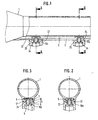
Fig. 1 : Einen Längsschnitt durch einen Teil eines Zielfernrohres und durch eine erste Ausführungsform einer Einrichtung zur Befestigung desselben an einer nicht-dargestellten Waffe; -
Fig. 2 und 3 : Einen Schnitt entlang der Linie entlang der Linie II-II bzw. III-III nachFig. 1 ; -
Fig. 4 : Einen Querschnitt durch das Zielfernrohr nachFig. 1-3 ohne Befestigungseinrichtung; -
Fig. 5 : Eine Draufsicht auf das Zielfernrohr von unten; -
Fig. 6 : Eine Draufsicht auf das Klemmteil von unten; -
Fig. 7 : Einen Schnitt durch das Klemmteil entlang der Linie VII-VII; -
Fig. 8 : Einen Längsschnitt durch einen Teil eines Zielfernrohres und durch eine Einrichtung zur Befestigung desselben an einer Waffe nach einer weiteren Ausführungsform; -
Fig. 9 : Einen Querschnitt entlang der Linie IX-IX inFig. 8 ; -
Fig. 10 : Einen Längsschnitt durch den Teil eines Zielfernrohres und durch eine Einrichtung zur Befestigung desselben an einer Waffe nach noch einer anderen Ausführungsform; -
Fig. 11 : Einen Querschnitt entlang der Linie XI-XI inFig. 10 ; -
Fig. 12 : Eine Seitenansicht des Einsatzes der Befestigungseinrichtung nachFig. 10 und11 ; und -
Fig. 13 : Eine Schutzabdeckung für das Zielfernrohr. - Gemäß
Fig. 1 bis 7 weist das Zielfernrohr 1 eine Montageschiene 2 auf, die sich zumindest über einen Teil der Länge des Zielfernrohres 1 erstreckt. Die Montageschiene 2 stützt sich auf zwei im Abstand auf der nicht-dargestellten Waffe befestigten Lagern oder Montagevorrichtungen 3a, 3b ab. Die Montageschiene 2 ist als Hohlprofil ausgebildet, d.h. sie weist eine Längsnut 5 mit einer Längsöffnung 6 auf (Fig. 6 ). In die Längsnut 5 ist ein Klemmteil 7 geschoben. Um das Klemmteil 7 in die Nut 5 schieben zu können, weist die Öffnung 6 an einem Ende einen größeren Querschnitt auf. - Das Klemmteil 7 ist mit einem Innengewinde 9 versehen, in das eine Befestigungsschraube 8 eingreift, welche eine Öffnung 11a, 11b in den Montagevorrichtungen 3a, 3b durchragt. Mit ihrem Kopf 4 stützt sich die Schraube 8 an einer Innenschulter 10a, 10b in der Montagevorrichtung 3a bzw. 3b ab.
- Das Klemmteil 7 erstreckt sich in die Öffnungen 11a, 11b der Montagevorrichtung 3a, 3b hinein. Es ist dazu im Querschnitt T-förmig ausgebildet. Der senkrechte Balken des T bildet einen hülsenförmigen Abschnitt 12, während der Querbalken des T einen Kopf 13 bildet, der an seiner Unterseite beiderseits des Abschnitts 12 sich zum Abschnitt 12 hin keilförmig dicker werdende Klemmflächen 14, 15 aufweist (
Fig. 6 und 7 ), die mit entsprechend geneigten Klemmflächen 16, 17 in der Längsnut 5 beiderseits der Längsöffnung 6 zusammenwirken. - Durch den hülsenförmigen Abschnitt 12 und den Kopf 13 erstreckt sich eine Bohrung mit dem Innengewinde 9. Der hülsenförmige Abschnitt 12 der Klemmteile 7 erstreckt sich durch die Längsöffnung 6 in der Montageschiene 2 hindurch und in die Öffnungen 11a, 11b der beiden Montagevorrichtung 3a, 3b hinein. Das Klemmteil 7 weist damit eine Bauhöhe 18 auf (
Fig. 7 ), die wesentlich größer ist als die Bauhöhe des Innenprofils der Längsnut 5. Damit kann die Montageschiene 2 eine geringe Bauhöhe 19 aufweisen (Fig. 4 ). Der hülsenförmige Abschnitt 12 des Klemmteils 7 liegt mit seinem Außenumfang 21 an beiden Seiten an der Wandung der Öffnung 6 der Längsnut 5 an, ferner liegt sein Außenumfang formschlüssig an der Wandung der Öffnungen 11a, 11b der Montagevorrichtungen 3a, 3b an. - Die Montageschiene 2 ist beiderseits der Längsöffnungen 6 an einem Ende im Bereich der Montagevorrichtung 3a an der der Montagevorrichtung 3a zugewandten Seite mit einer Verzahnung 22 vorgesehen. Die Montagevorrichtung 3a wiest ihrerseits auf der der Montageschiene 2 zugewandten Seite in Längsrichtung des Zielfernrohres 1 vor und hinter der Befestigungsschraube 8 jeweils zahnförmige Vorsprünge 23 auf, die in die Verzahnung 22 an der Montageschiene 2 eingreifen. Die Zähne 23 und die Zähne der Verzahnung 22 können beispielsweise trapezförmig oder rechteckig ausgebildet sein. Demgegenüber liegt die Montageschiene 2 im Bereich der anderen Montagevorrichtung 3b mit planer Fläche 24 auf der planen Fläche 25 der Montagevorrichtung 3b auf (
Fig. 1 und 3 ). - Die Ausführungsform nach
Fig. 8 und9 unterscheidet sich von derjenigen nachFigur 1-7 im Wesentlichen dadurch, daß die Montagevorrichtung 3 als einteilige Schiene ausgebildet ist, die an der der Montageschiene 2 zugewandten Seite eine flache, im Querschnitt rechteckige Längsnut 26 aufweist, in die ein im Querschnitt rechteckiger Vorsprung 30 an der Montageschiene 2 formschlüssig eingreift. Die sich entlang der nicht-dargestellten Waffe erstreckende Schiene 3 ist mit Öffnungen 11a, 11b versehen, durch die sich jeweils eine Befestigungsschraube 8 in jeweils ein Klemmteil 7 erstreckt. - Nach
Fig. 10 und11 ist in der Montagevorrichtung 3 an der einen Öffnung 11a ein Einsatz 27 vorgesehen, der inFig. 12 gesondert dargestellt ist. Der Einsatz 27 ist mit den Zähnen 23 versehen (Fig. 12 ), die in die Verzahnung 22 an der Montageschiene 2 des Zielfernrohres 1 eingreifen. - Der Einsatz 27 ist im Querschnitt T-förmig ausgebildet, wobei der senkrechte Balken des T den Abschnitt bildet, mit dem der Einsatz 27 die Öffnung 11a in der Montagevorrichtung 3 durchragt, auch ist er mit den Zähnen 23 versehen ist, die in die Verzahnung 22 eingreifen. Demgegenüber stützt sich der Querbalken des T auf der Innenschulter 28 in der Montagevorrichtung 3 an dem von der Montageschiene 2 abgewandten Ende der Öffnung 11a ab.
- Weiterhin weist der Einsatz 27 seinerseits eine Innenschulter 29 auf, an der sich der Kopf 4 der Schraube 8 abstützt. Schließlich weist der Einsatz 27 eine Innenausnehmung 31 auf, in die sich der hülsenförmige Abschnitt 12 des Klemmteils 7 erstreckt. Wenn bei der Montagevorrichtung 3 nach
Fig. 10 und11 die Zähne 23 gegenüber der Zylinderachse 33 des Einsatzes 27 um eine 1/4-Teilung t der Verzahnung 22 versetzt sind, kann je nach Einbaulage des Einsatzes 27 die axiale Länge des Zielfernrohr relativ zu der Montagevorrichtung 3 auf eine 1/2-Teilung t genau fixiert werden. - Gemäß
Fig. 13 kann die Lösungsöffnung 6 der Monageschiene 2 in den nicht durch die Montagevorrichtungen 3a, 3b abegedeckten Bereichen mit einer im Querschnitt T-förmigen Abdeckung 32 verschlossen werden, welche mit dem senkrechten Balken des T in die Längsnut 5 der Montageschiene 2 eingreift, während der Querbalken T die Seite der Montageschiene 2 übergreift, die bei montiertem Zielfernrohr 1 der Montagevorrichtung 3, 3a, 3b zugewandt ist. Durch die Abdeckung 32 wird die Längsnut 5 vor Verschmutzung geschützt. Auch wird das Erscheinungsbild des Zielfernrohr 1 durch Abdecken der Verzahnung 22 verbessert. Die Abdeckung 35 wird vorzugsweise aus einem leicht schneidbaren Material hergestellt. So kann die benötigte Länge der Abdeckung 32 an die jeweilige Montage auf einfache Weise angepaßt werden.
Claims (13)
- Befestigungseinrichtung für ein Zielfernrohr (1) an einer Waffe mit einer mit dem Zielfernrohrgehäuse verbundenen, sich entlang dem Zielfernrohr (1) erstreckenden Montageschiene (2), die sich auf wenigstens einer an der Waffe befestigten Montagevorrichtung (3a,3b) abstützt und eine Längsnut (5) aufweist, in die ein dem Innenprofil der Nut entsprechendes Klemmteil (7) geschoben ist, das mit einer Befestigungsschraube (8) festgelegt wird, welche durch eine erste Offnung (11a,11b) in der Montagevorrichtung (3a,3b) in ein Gewinde (9) in dem Klemmteil (7) eingreift, dadurch gekennzeichnet, daß die Montageschiene (2) an der der Montagevorrichtung (3, 3a, 3b) zugewandten Seite mit einer Verzahnung (22) versehen ist, in die wenigstens ein mit der Montagevorrichtung (3, 3a, 3b) verbundener erster Vorsprung (23) eingreift.
- Befestigungseinrichtung nach Anspruch 1, dadurch gekennzeichnet, daß sich das Klemmteil (7) in die erste Offnung (11a, 11b) in der Montagevorrichtung (3, 3a, 3b) erstreckt.
- Befestigungseinrichtung nach Anspruch 1 oder 2, dadurch gekennzeichnet, daß das Klemmteil (7) sowohl mit der zweiten Offnung (6) der Längsnut (5) der Montageschiene (2) wie mit der ersten Offnung (11a, 11b) in der Montagevorrichtung (3, 3a, 3b) formschlüssig ausgebildet ist.
- Befestigungseinrichtung nach einem der vorstehenden Ansprüche, dadurch gekennzeichnet, daß das Klemmteil (7) T-förmig ausgebildet ist, wobei der senkrechte Balken des T einen hülsenförmigen Abschnitt (12) bildet, durch den sich das Innengewinde für die Befestigungsschraube (8) erstreckt, während der Querbalken des T an seiner Unterseite beiderseits des senkrechten Balkens Klemmflächen (14, 15) aufweist, die mit Klemmflächen (16, 17) des Innenprofils der Nut (5) der Montageschiene (2) zusammenwirken.
- Befestigungseinrichtung nach Anspruch 4, dadurch gekennzeichnet, daß der hülsenförmige Abschnitt (12) in die erste Offnung (11a, 11b) der Montagevorrichtung (3, 3a, 3b) ragt.
- Befestigungseinrichtung nach Anspruch 4 oder 5, dadurch gekennzeichnet, daß der hülsenförmige Abschnitt (12) sowohl mit der zweite Offnung (6) der Längsnut (5) der Montageschiene (2) wie mit der ersten Offnung (11a,11b) in der Montagevorrichtung (3, 3a, 3b) formschlüssig ausgebildet ist.
- Befestigungseinrichtung nach einem der vorstehenden Ansprüche, dadurch gekennzeichnet, daß die Montagevorrichtung (3, 3a, 3b) eine zweite Längsnut (26), aufweist, in die ein sich entlang der Montageschiene (2) erstreckender zweiter Vorsprung (30) formschlüssig eingreift.
- Befestigungseinrichtung nach Anspruch 7, dadurch gekennzeichnet, daß die zweite Nut (26) und der zweite Vorsprung (30) rechteckig ausgebildet sind.
- Befestigungseinrichtung nach Anspruch 1, dadurch gekennzeichnet, daß der wenigstens eine erste Vorsprung (23), der in die Verzahnung (22) der Montageschiene (2) eingreift, an einem Einsatz (27) vorgesehen ist.
- Befestigungseinrichtung nach Anspruch 9, dadurch gekennzeichnet, daß der Einsatz (27) einem mit der ersten Offnung (11a) der Montagevorrichtung (3) formschlüssigen Außenumfang aufweist.
- Befestigungseinrichtung nach Anspruch 9 oder 10, dadurch gekennzeichnet, daß der Einsatz (27) T-förmig ausgebildet ist, wobei der senkrechte Balken des T den Abschnitt bildet, mit dem der Einsatz (27) die erste Öffnung (11a) in der Montagevorrichtung (3) durchragt, während sich der Querbalken des T auf einer Innenschulter (28) an dem von der Montageschiene (2) abgewandten Ende der ersten Öffnung (11a) in der Montagevorrichtung (3) abstützt.
- Befestigungseinrichtung nach einem der Ansprüche 9-11, dadurch gekennzeichnet, daß sich das Klemmteil (7) in den Einsatz (27) in der Montagevorrichtung (3) erstreckt.
- Befestigungseinrichtung nach einem der vorstehenden Ansprüche, dadurch gekennzeichnet, daß die Montagevorrichtung (3) als Schiene ausgebildet ist, die wenigstens zwei ersten Öffnungen (11a, 11b) aufweist, die jeweils eine Befestigungsschraube (8) aufnehmen, die in ein Klemmteil (7) in der Längsnut (5) der Montageschiene (2) eingreifen.
Priority Applications (4)
| Application Number | Priority Date | Filing Date | Title |
|---|---|---|---|
| EP02015263A EP1380807B1 (de) | 2002-07-09 | 2002-07-09 | Befestigungseinrichtung für ein Zielfernrohr an einer Waffe |
| AT02015263T ATE480748T1 (de) | 2002-07-09 | 2002-07-09 | Befestigungseinrichtung für ein zielfernrohr an einer waffe |
| DE50214644T DE50214644D1 (de) | 2002-07-09 | 2002-07-09 | Befestigungseinrichtung für ein Zielfernrohr an einer Waffe |
| US10/443,993 US6901692B2 (en) | 2002-07-09 | 2003-05-23 | Fastening device for an aiming telescope on a weapon |
Applications Claiming Priority (1)
| Application Number | Priority Date | Filing Date | Title |
|---|---|---|---|
| EP02015263A EP1380807B1 (de) | 2002-07-09 | 2002-07-09 | Befestigungseinrichtung für ein Zielfernrohr an einer Waffe |
Publications (2)
| Publication Number | Publication Date |
|---|---|
| EP1380807A1 EP1380807A1 (de) | 2004-01-14 |
| EP1380807B1 true EP1380807B1 (de) | 2010-09-08 |
Family
ID=29724417
Family Applications (1)
| Application Number | Title | Priority Date | Filing Date |
|---|---|---|---|
| EP02015263A Expired - Lifetime EP1380807B1 (de) | 2002-07-09 | 2002-07-09 | Befestigungseinrichtung für ein Zielfernrohr an einer Waffe |
Country Status (4)
| Country | Link |
|---|---|
| US (1) | US6901692B2 (de) |
| EP (1) | EP1380807B1 (de) |
| AT (1) | ATE480748T1 (de) |
| DE (1) | DE50214644D1 (de) |
Families Citing this family (20)
| Publication number | Priority date | Publication date | Assignee | Title |
|---|---|---|---|---|
| DE10111442B4 (de) * | 2001-03-09 | 2014-11-20 | Maquet Gmbh & Co. Kg | Anordnung zum lösbaren Verbinden zweier stumpf aneinander stoßender Bauteile |
| US7121037B2 (en) * | 2004-06-14 | 2006-10-17 | Robert Nils Penney | External adjustable telescopic scope device |
| US20080022576A1 (en) * | 2006-07-27 | 2008-01-31 | Epling J Patrick | Octagonal Scope and Ring Mount |
| US9267753B2 (en) * | 2011-09-28 | 2016-02-23 | Cadex, Inc. | Recoil force mitigating device for firearms |
| US9239210B2 (en) * | 2014-04-03 | 2016-01-19 | Magpul Industries Corp. | Firearm accessory mounting interface |
| US9709358B2 (en) * | 2014-10-22 | 2017-07-18 | Bravo Company USA, Inc. | Coupling various firearm accessories to a firearm |
| US20170030682A1 (en) * | 2015-07-31 | 2017-02-02 | Paul Arthur Pearson | Rifle Scope Mounting System |
| US10900743B2 (en) | 2016-05-12 | 2021-01-26 | Bravo Company Mfg, Inc. | Firearm handguard assembly |
| US9791239B1 (en) | 2016-05-12 | 2017-10-17 | Bravo Company Mfg. Inc. | Firearm handguard assembly |
| US10295304B1 (en) | 2016-05-12 | 2019-05-21 | Bravo Company Mfg, Inc. | Firearm handguard assembly |
| US10260841B2 (en) | 2016-10-20 | 2019-04-16 | Bravo Company Mfg, Inc. | Firearm accessory mounting system |
| US10260838B1 (en) | 2016-10-20 | 2019-04-16 | Bravo Company Mfg, Inc. | Firearm handguard |
| USD844091S1 (en) | 2016-10-20 | 2019-03-26 | Bravo Company Mfg, Inc. | Firearm handguard |
| US10551145B2 (en) | 2017-10-18 | 2020-02-04 | Bravo Company Mfg, Inc. | Modular key-slot accessory mounting system for a firearm |
| WO2020060723A2 (en) | 2018-08-24 | 2020-03-26 | Bravo Company Mfg, Inc. | Firearm accessory mounting assembly |
| USD912189S1 (en) | 2019-04-29 | 2021-03-02 | Bravo Company Mfg, Inc. | Firearm handguard |
| US11543212B1 (en) * | 2019-11-22 | 2023-01-03 | Phillip Letts | Indexing scope mount assembly |
| US11982512B2 (en) * | 2020-02-24 | 2024-05-14 | Phillip Gerlings | Firearm accessory mounting system |
| US12055367B2 (en) * | 2021-10-13 | 2024-08-06 | Shanyao Lee | Optics mount with slope and teeth |
| US12235071B2 (en) * | 2022-06-29 | 2025-02-25 | Daniel Defense, Llc | Systems and methods for an adjustable weight assembly for a firearm |
Family Cites Families (5)
| Publication number | Priority date | Publication date | Assignee | Title |
|---|---|---|---|---|
| US2583260A (en) * | 1950-06-28 | 1952-01-22 | Thomas R Felix | Telescope sight mount for firearms |
| US2649779A (en) * | 1953-01-07 | 1953-08-25 | Robert R Hardgrove | Detachable telescope sight mount |
| US2854748A (en) * | 1954-10-13 | 1958-10-07 | Harvey A Williams | Mount for gun sight |
| DE962410C (de) * | 1955-07-09 | 1957-04-18 | J G Anschuetz G M B H | Seitenfeineinstellung fuer Zielfernrohre |
| DE3820471A1 (de) * | 1988-06-16 | 1989-12-28 | Zeiss Carl Fa | Befestigungseinrichtung fuer ein zielfernrohr |
-
2002
- 2002-07-09 AT AT02015263T patent/ATE480748T1/de active
- 2002-07-09 EP EP02015263A patent/EP1380807B1/de not_active Expired - Lifetime
- 2002-07-09 DE DE50214644T patent/DE50214644D1/de not_active Expired - Lifetime
-
2003
- 2003-05-23 US US10/443,993 patent/US6901692B2/en not_active Expired - Lifetime
Also Published As
| Publication number | Publication date |
|---|---|
| DE50214644D1 (de) | 2010-10-21 |
| US20040009034A1 (en) | 2004-01-15 |
| EP1380807A1 (de) | 2004-01-14 |
| ATE480748T1 (de) | 2010-09-15 |
| US6901692B2 (en) | 2005-06-07 |
Similar Documents
| Publication | Publication Date | Title |
|---|---|---|
| EP1380807A1 (de) | Befestigungseinrichtung für ein Zielfernrohr an einer Waffe | |
| EP2339287B1 (de) | Klemmsystem für Zusatzgeräte auf einer Picatinny-Schiene | |
| EP0503305B1 (de) | Dachgepäckträger für Kraftfahrzeuge mit Dachreling | |
| DE102018221183B3 (de) | Justierbeschlag und Tragsystem für Solarmodule | |
| EP3106826B1 (de) | Adapterstück und handfeuerwaffe mit einem solchen adapterstück | |
| DE10025839C1 (de) | Ausleger | |
| DE102011010940A1 (de) | Vorrichtung zur Bettung eines Verschlussgehäuses und/oder eines Laufs in einem Schaft einer Handfeuerwaffe | |
| EP3130717B1 (de) | Pfosten-riegel-verbindung | |
| EP1111249A2 (de) | Klemmvorrichtung | |
| DE102007034432B4 (de) | Schalungselement für Rundschalungen | |
| EP2245412B1 (de) | Vorrichtung zur befestigung eines zusatzteils, insbesondere einer zieleinrichtung, an einer waffe | |
| DE102006024508B4 (de) | Halterung für Zusatzgeräte an Feuerwaffen | |
| EP2775254A1 (de) | Seitenmontage zur Befestigung einer Zusatzeinrichtung an einer Waffe | |
| EP1713991B1 (de) | Türdrückerpaar mit Türdrückerklemmbefestigung | |
| EP1380808A1 (de) | Befestigungseinrichtung für ein Zielfernrohr an einer Waffe | |
| EP0086329B1 (de) | Verbindungsvorrichtung | |
| DE102018101285A1 (de) | Eckverbinder | |
| DE10340196B4 (de) | Schlossmoduleinrichtung für eine Kraftfahrzeugtür | |
| DE102004048879A1 (de) | Anlenkung | |
| EP2394131B1 (de) | Vorrichtung zur befestigung einer zusatzeinrichtung an einer waffe | |
| EP1036945B1 (de) | Bausatz mit einer Vorrichtung zur verstellbaren Befestigung von festen oder beweglichen Platten | |
| EP3546767B1 (de) | Verbinder für profile eines baukastensystems und baukastensystem | |
| DE202005010983U1 (de) | Halterung für Sonnenschutzanlagen | |
| DE29905418U1 (de) | Vorrichtung zur lösbaren Befestigung einer Gebäudeplatte | |
| DE8912521U1 (de) | Sicherheitsbeschlag für Türen |
Legal Events
| Date | Code | Title | Description |
|---|---|---|---|
| PUAI | Public reference made under article 153(3) epc to a published international application that has entered the european phase |
Free format text: ORIGINAL CODE: 0009012 |
|
| 17P | Request for examination filed |
Effective date: 20020709 |
|
| AK | Designated contracting states |
Kind code of ref document: A1 Designated state(s): AT BE BG CH CY CZ DE DK EE ES FI FR GB GR IE IT LI LU MC NL PT SE SK TR |
|
| AX | Request for extension of the european patent |
Extension state: AL LT LV MK RO SI |
|
| AKX | Designation fees paid |
Designated state(s): AT BE BG CH CY CZ DE DK EE ES FI FR GB GR IE IT LI LU MC NL PT SE SK TR |
|
| 17Q | First examination report despatched |
Effective date: 20070906 |
|
| GRAP | Despatch of communication of intention to grant a patent |
Free format text: ORIGINAL CODE: EPIDOSNIGR1 |
|
| GRAS | Grant fee paid |
Free format text: ORIGINAL CODE: EPIDOSNIGR3 |
|
| GRAA | (expected) grant |
Free format text: ORIGINAL CODE: 0009210 |
|
| AK | Designated contracting states |
Kind code of ref document: B1 Designated state(s): AT BE BG CH CY CZ DE DK EE ES FI FR GB GR IE IT LI LU MC NL PT SE SK TR |
|
| REG | Reference to a national code |
Ref country code: GB Ref legal event code: FG4D Free format text: NOT ENGLISH |
|
| REG | Reference to a national code |
Ref country code: CH Ref legal event code: EP Ref country code: CH Ref legal event code: NV Representative=s name: E. BLUM & CO. AG PATENT- UND MARKENANWAELTE VSP |
|
| REG | Reference to a national code |
Ref country code: IE Ref legal event code: FG4D Free format text: LANGUAGE OF EP DOCUMENT: GERMAN |
|
| REF | Corresponds to: |
Ref document number: 50214644 Country of ref document: DE Date of ref document: 20101021 Kind code of ref document: P |
|
| REG | Reference to a national code |
Ref country code: NL Ref legal event code: VDEP Effective date: 20100908 |
|
| PG25 | Lapsed in a contracting state [announced via postgrant information from national office to epo] |
Ref country code: FI Free format text: LAPSE BECAUSE OF FAILURE TO SUBMIT A TRANSLATION OF THE DESCRIPTION OR TO PAY THE FEE WITHIN THE PRESCRIBED TIME-LIMIT Effective date: 20100908 |
|
| PG25 | Lapsed in a contracting state [announced via postgrant information from national office to epo] |
Ref country code: CY Free format text: LAPSE BECAUSE OF FAILURE TO SUBMIT A TRANSLATION OF THE DESCRIPTION OR TO PAY THE FEE WITHIN THE PRESCRIBED TIME-LIMIT Effective date: 20100908 |
|
| REG | Reference to a national code |
Ref country code: IE Ref legal event code: FD4D |
|
| PG25 | Lapsed in a contracting state [announced via postgrant information from national office to epo] |
Ref country code: GR Free format text: LAPSE BECAUSE OF FAILURE TO SUBMIT A TRANSLATION OF THE DESCRIPTION OR TO PAY THE FEE WITHIN THE PRESCRIBED TIME-LIMIT Effective date: 20101209 Ref country code: SE Free format text: LAPSE BECAUSE OF FAILURE TO SUBMIT A TRANSLATION OF THE DESCRIPTION OR TO PAY THE FEE WITHIN THE PRESCRIBED TIME-LIMIT Effective date: 20100908 Ref country code: NL Free format text: LAPSE BECAUSE OF FAILURE TO SUBMIT A TRANSLATION OF THE DESCRIPTION OR TO PAY THE FEE WITHIN THE PRESCRIBED TIME-LIMIT Effective date: 20100908 |
|
| PG25 | Lapsed in a contracting state [announced via postgrant information from national office to epo] |
Ref country code: IE Free format text: LAPSE BECAUSE OF FAILURE TO SUBMIT A TRANSLATION OF THE DESCRIPTION OR TO PAY THE FEE WITHIN THE PRESCRIBED TIME-LIMIT Effective date: 20100908 |
|
| PG25 | Lapsed in a contracting state [announced via postgrant information from national office to epo] |
Ref country code: SK Free format text: LAPSE BECAUSE OF FAILURE TO SUBMIT A TRANSLATION OF THE DESCRIPTION OR TO PAY THE FEE WITHIN THE PRESCRIBED TIME-LIMIT Effective date: 20100908 Ref country code: PT Free format text: LAPSE BECAUSE OF FAILURE TO SUBMIT A TRANSLATION OF THE DESCRIPTION OR TO PAY THE FEE WITHIN THE PRESCRIBED TIME-LIMIT Effective date: 20110110 Ref country code: IT Free format text: LAPSE BECAUSE OF FAILURE TO SUBMIT A TRANSLATION OF THE DESCRIPTION OR TO PAY THE FEE WITHIN THE PRESCRIBED TIME-LIMIT Effective date: 20100908 Ref country code: EE Free format text: LAPSE BECAUSE OF FAILURE TO SUBMIT A TRANSLATION OF THE DESCRIPTION OR TO PAY THE FEE WITHIN THE PRESCRIBED TIME-LIMIT Effective date: 20100908 |
|
| PG25 | Lapsed in a contracting state [announced via postgrant information from national office to epo] |
Ref country code: ES Free format text: LAPSE BECAUSE OF FAILURE TO SUBMIT A TRANSLATION OF THE DESCRIPTION OR TO PAY THE FEE WITHIN THE PRESCRIBED TIME-LIMIT Effective date: 20101219 |
|
| PLBE | No opposition filed within time limit |
Free format text: ORIGINAL CODE: 0009261 |
|
| STAA | Information on the status of an ep patent application or granted ep patent |
Free format text: STATUS: NO OPPOSITION FILED WITHIN TIME LIMIT |
|
| 26N | No opposition filed |
Effective date: 20110609 |
|
| PG25 | Lapsed in a contracting state [announced via postgrant information from national office to epo] |
Ref country code: DK Free format text: LAPSE BECAUSE OF FAILURE TO SUBMIT A TRANSLATION OF THE DESCRIPTION OR TO PAY THE FEE WITHIN THE PRESCRIBED TIME-LIMIT Effective date: 20100908 |
|
| REG | Reference to a national code |
Ref country code: DE Ref legal event code: R097 Ref document number: 50214644 Country of ref document: DE Effective date: 20110609 |
|
| PG25 | Lapsed in a contracting state [announced via postgrant information from national office to epo] |
Ref country code: MC Free format text: LAPSE BECAUSE OF NON-PAYMENT OF DUE FEES Effective date: 20110731 |
|
| PG25 | Lapsed in a contracting state [announced via postgrant information from national office to epo] |
Ref country code: LU Free format text: LAPSE BECAUSE OF NON-PAYMENT OF DUE FEES Effective date: 20110709 |
|
| PG25 | Lapsed in a contracting state [announced via postgrant information from national office to epo] |
Ref country code: TR Free format text: LAPSE BECAUSE OF FAILURE TO SUBMIT A TRANSLATION OF THE DESCRIPTION OR TO PAY THE FEE WITHIN THE PRESCRIBED TIME-LIMIT Effective date: 20100908 Ref country code: BG Free format text: LAPSE BECAUSE OF FAILURE TO SUBMIT A TRANSLATION OF THE DESCRIPTION OR TO PAY THE FEE WITHIN THE PRESCRIBED TIME-LIMIT Effective date: 20101208 |
|
| PGFP | Annual fee paid to national office [announced via postgrant information from national office to epo] |
Ref country code: CH Payment date: 20140722 Year of fee payment: 13 |
|
| PGFP | Annual fee paid to national office [announced via postgrant information from national office to epo] |
Ref country code: GB Payment date: 20140721 Year of fee payment: 13 Ref country code: FR Payment date: 20140724 Year of fee payment: 13 |
|
| PGFP | Annual fee paid to national office [announced via postgrant information from national office to epo] |
Ref country code: BE Payment date: 20140722 Year of fee payment: 13 |
|
| REG | Reference to a national code |
Ref country code: CH Ref legal event code: PL |
|
| GBPC | Gb: european patent ceased through non-payment of renewal fee |
Effective date: 20150709 |
|
| PG25 | Lapsed in a contracting state [announced via postgrant information from national office to epo] |
Ref country code: GB Free format text: LAPSE BECAUSE OF NON-PAYMENT OF DUE FEES Effective date: 20150709 Ref country code: LI Free format text: LAPSE BECAUSE OF NON-PAYMENT OF DUE FEES Effective date: 20150731 Ref country code: CH Free format text: LAPSE BECAUSE OF NON-PAYMENT OF DUE FEES Effective date: 20150731 |
|
| REG | Reference to a national code |
Ref country code: FR Ref legal event code: ST Effective date: 20160331 |
|
| PG25 | Lapsed in a contracting state [announced via postgrant information from national office to epo] |
Ref country code: FR Free format text: LAPSE BECAUSE OF NON-PAYMENT OF DUE FEES Effective date: 20150731 |
|
| PG25 | Lapsed in a contracting state [announced via postgrant information from national office to epo] |
Ref country code: BE Free format text: LAPSE BECAUSE OF NON-PAYMENT OF DUE FEES Effective date: 20150731 |
|
| PGFP | Annual fee paid to national office [announced via postgrant information from national office to epo] |
Ref country code: DE Payment date: 20180823 Year of fee payment: 17 |
|
| PGFP | Annual fee paid to national office [announced via postgrant information from national office to epo] |
Ref country code: CZ Payment date: 20180629 Year of fee payment: 17 Ref country code: AT Payment date: 20180719 Year of fee payment: 17 |
|
| PG25 | Lapsed in a contracting state [announced via postgrant information from national office to epo] |
Ref country code: CZ Free format text: LAPSE BECAUSE OF NON-PAYMENT OF DUE FEES Effective date: 20190709 |
|
| REG | Reference to a national code |
Ref country code: DE Ref legal event code: R119 Ref document number: 50214644 Country of ref document: DE |
|
| REG | Reference to a national code |
Ref country code: AT Ref legal event code: MM01 Ref document number: 480748 Country of ref document: AT Kind code of ref document: T Effective date: 20190709 |
|
| PG25 | Lapsed in a contracting state [announced via postgrant information from national office to epo] |
Ref country code: AT Free format text: LAPSE BECAUSE OF NON-PAYMENT OF DUE FEES Effective date: 20190709 Ref country code: DE Free format text: LAPSE BECAUSE OF NON-PAYMENT OF DUE FEES Effective date: 20200201 |