EP1380798B1 - Arrangement of burner and heat exchanger, and air-heating apparatus - Google Patents
Arrangement of burner and heat exchanger, and air-heating apparatus Download PDFInfo
- Publication number
- EP1380798B1 EP1380798B1 EP02077787A EP02077787A EP1380798B1 EP 1380798 B1 EP1380798 B1 EP 1380798B1 EP 02077787 A EP02077787 A EP 02077787A EP 02077787 A EP02077787 A EP 02077787A EP 1380798 B1 EP1380798 B1 EP 1380798B1
- Authority
- EP
- European Patent Office
- Prior art keywords
- heat exchanger
- burner
- exchange elements
- heat
- heat exchange
- Prior art date
- Legal status (The legal status is an assumption and is not a legal conclusion. Google has not performed a legal analysis and makes no representation as to the accuracy of the status listed.)
- Expired - Lifetime
Links
Images


Classifications
-
- F—MECHANICAL ENGINEERING; LIGHTING; HEATING; WEAPONS; BLASTING
- F24—HEATING; RANGES; VENTILATING
- F24H—FLUID HEATERS, e.g. WATER OR AIR HEATERS, HAVING HEAT-GENERATING MEANS, e.g. HEAT PUMPS, IN GENERAL
- F24H3/00—Air heaters
- F24H3/02—Air heaters with forced circulation
- F24H3/06—Air heaters with forced circulation the air being kept separate from the heating medium, e.g. using forced circulation of air over radiators
- F24H3/10—Air heaters with forced circulation the air being kept separate from the heating medium, e.g. using forced circulation of air over radiators by plates
- F24H3/105—Air heaters with forced circulation the air being kept separate from the heating medium, e.g. using forced circulation of air over radiators by plates using fluid fuel
-
- F—MECHANICAL ENGINEERING; LIGHTING; HEATING; WEAPONS; BLASTING
- F28—HEAT EXCHANGE IN GENERAL
- F28D—HEAT-EXCHANGE APPARATUS, NOT PROVIDED FOR IN ANOTHER SUBCLASS, IN WHICH THE HEAT-EXCHANGE MEDIA DO NOT COME INTO DIRECT CONTACT
- F28D9/00—Heat-exchange apparatus having stationary plate-like or laminated conduit assemblies for both heat-exchange media, the media being in contact with different sides of a conduit wall
- F28D9/0031—Heat-exchange apparatus having stationary plate-like or laminated conduit assemblies for both heat-exchange media, the media being in contact with different sides of a conduit wall the conduits for one heat-exchange medium being formed by paired plates touching each other
- F28D9/0043—Heat-exchange apparatus having stationary plate-like or laminated conduit assemblies for both heat-exchange media, the media being in contact with different sides of a conduit wall the conduits for one heat-exchange medium being formed by paired plates touching each other the plates having openings therein for circulation of at least one heat-exchange medium from one conduit to another
Definitions
- the heat exchanger elements 3 are produced from high temperature materials, such as high temperature steels (e.g., a stainless steel) and high temperature alloys, which possess sufficient mechanical strength and corrosion resistance at high temperature.
- high temperature steels e.g., a stainless steel
- high temperature alloys which possess sufficient mechanical strength and corrosion resistance at high temperature.
- the burner and heat exchanger arrangement comprise an additional condensation unit CU located at the gas outlet H.
- the condensation unit CU further increases the energy efficiency of the burner and heat exchanger arrangement by condensation of moisture from the heated gas.
Abstract
Description
- The present invention relates to an arrangement of a burner and heat exchanger as defined in the preamble of claim 1. Also, the invention relates to an air-heating apparatus comprising such an arrangement of a burner and heat exchanger. Further, the invention relates to a method for such an air-heating apparatus.
- Air-heating apparatuses are well known in the art for heating of large spaces such as storage warehouses and workshops. In such an air-heating apparatus a burner section and a heat exchanger section are separately present.
- The burner section is used as energy source and provides energy in the form of heated matter at it's outlet to the heat exchanger section. The heated matter may be an exhaust gas or a fluid: most systems known in the art are gas-fired air heating apparatuses that use a gas burner device to burn a primary fuel gas (e.g., natural gas) and to produce high temperature exhaust gas as energy source.
- In the heat exchanger section of gas-fired air-heating apparatuses the energy content of the high temperature exhaust gas is used to heat a secondary gas (i.e., room air or process air) which is to be distributed in the space to be heated. The heat exchanger section consists of heat exchanger elements through which the high temperature exhaust gas is guided internally and where heat exchange between the high temperature exhaust gas and the process air takes place at the outer surface of those heat exchange elements. The process air may be forced by a blower to flow across the outer surface of the heat exchanger elements to enhance the exchange of heat.
- In relation to energy conservation and reduction of energy costs, the efficiency of air-heating apparatuses from the prior art may be regarded low. Mainly for historical reasons, the maximum temperature in the heat exchanging section is typically limited to about 450°C. Therefore the heat flux (heat flow per unit area) of an air-heating unit is low. To obtain a sufficiently large heat flow for adequate heating, the heat exchanger area of an air-heating unit must be large and consequently air-heating units from the prior art are relatively bulky. The actual flow needed relates to the size of the space to be heated and depends on the actual capacity of the air-heating apparatus. (In some cases more than one air-heating apparatus may be required in a particular space.) Disadvantageously, due to their bulky size, air-heating apparatuses reduce the useful floor (or wall) capacity of storage warehouses and the like.
-
US-A-2682867 discloses a floor furnace with tubular heating element, comprising a plurality of tubular heater elements each arranged with an external burner element - It is an object of the present invention to provide an air-heating apparatus that has better energy efficiency than air-heating systems from the prior art.
- Therefore, the present invention relates to an arrangement of a burner and heat exchanger as defined in claim 1.
- Further, the present invention relates to a method to be carried out by the arrangement according to claim 9 and to an air-heating apparatus comprising such an arrangement of a burner and a heat exchanger according to claim 12.
- Advantageously, the present invention allows an increase of the surface temperature of the heat exchanger to well above 450°C up to temperatures, e.g., up to 1000°C, preferably in the range of 700-800°C, where heat transfer is taking place substantially by radiation. A surface temperature of approx. 750°C may be used in the air-heating apparatus according to the present invention. Due to the higher temperature of the high temperature exhaust gas the efficiency of heat transfer in the heat exchanger is strongly improved.
- Also, by allowing high temperatures, the heat flux and heat transfer of a heat exchanger is strongly increased. Since the heat transfer is proportional to the cubic of the temperature difference between the incoming primary heat flow (i.e., high temperature exhaust gas) and secondary heat flow (i.e., process air), a two-fold increase of the temperature difference will result in an 8-fold increase of the energy in the outgoing secondary heat flow. As a consequence, for a given capacity of a heat exchanger, the heat exchanger in the air-heating apparatus according to the present invention can have a smaller size than a heat exchanger from the prior art. Advantageously, a more compact air-heating apparatus will need less floor- (or wall-) space than an air-heating apparatus from the prior art.
- In this respect, high temperature materials may be defined as materials which can withstand exposure to temperatures above 450°C during process time without a significant deterioration of their mechanical, physical and/or chemical properties. By using high temperature materials for the heat exchanger, the heat exchanger advantageously has improved thermal stability i.e., resistance to e.g., high temperature mechanical failure and high temperature corrosion.
- In a further preferred embodiment, the position of the burner inside the heat exchanger favours both the increase of the working temperature and the size reduction of the apparatus, due to the fact that the high temperature exhaust gas is generated directly in the heat exchanger.
- Below, the invention will be explained with reference to some drawings, which are intended for illustration purposes only and not to limit the scope of protection as defined in the accompanying claims.
-
Figure 1 shows a cross-sectional view of an arrangement of a burner and a heat exchanger according to the present invention; -
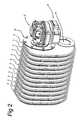
Figure 2 shows a perspective view of an arrangement of a burner and a heat exchanger according to the present invention; -
Figure 3 shows a perspective view of the burner and heat exchanger arrangement in a further embodiment. -
Figure 1 shows a cross-sectional view of an arrangement of a burner and a heat exchanger according to the present invention. The arrangement comprises a heat exchanger 1 and aburner 2. The heat exchanger 1 consists of a plurality of interconnectedheat exchange elements 3 forming a lamellar structure. In this lamellar structure theheat exchange elements 3 have preferably a substantially rectangular shape and are connected gastight to each other with a gap in between two adjacentheat exchange elements 3. Theheat exchange elements 3 compriseinlet duct parts 4 andoutlet duct parts 5 for connecting to each other. Aninlet duct part 4 andoutlet duct part 5 are preferably integral parts of anelement 3, but also may be separate parts for connection to aheat exchange element 3. InFigure 1 theducts ducts heat exchanger element 3. - On one sidewall A of the heat exchanger 1 an end heat exchange element 3' is located which comprises an
inlet duct part 4 and anoutlet duct part 5 on only one of it's sides. - On the opposite sidewall B of the heat exchanger 1, the
burner 2 is connected. Theburner 2 is a gas-fired burner and is connected to an outer inlet duct part 4' of the heat exchanger 1. Outer inlet duct 4' may be provided with a flange for connecting theburner 2. Theburner 2 receives fuel gas at a burner inlet F. A gas outlet H is located on the outer outlet duct part 5'. Outer outlet duct 5' may be provided with a flange for connecting other ducts. - When the
burner 2 is in use, the burning process produces high temperature exhaust gas which are directed into the heat exchanger 1. The high temperature exhaust gas flows from theburner 2 through theinlet duct parts 4, theheat exchange elements 3, and theoutlet duct parts 5 to the gas outlet H. InFigure 1 , theburner 2 is located at the same sidewall B of the heat exchanger 1 as the gas outlet H. It will be appreciated that the gas outlet H may be located at an opposite location H' at sidewall A of the heat exchanger 1. - In the heat exchanger 1 according to the present invention, the flow of process air to be heated is perpendicular to the drawing surface of
Figure 1 . -
Figure 2 shows a perspective view of an arrangement of theburner 2 and the heat exchanger 1 according to the present invention. InFigure 2 , entities with the same reference numbers refer to the same entities as shown inFigure 1 . - It is known that the larger the temperature difference between the relatively hot
heat exchange elements 3 and the relatively cold incoming process air flow, the larger the heat transfer to the process air flow will be. Thus, to enhance the energy efficiency of the heat exchanger 1, increasing the surface temperature of theheat exchange elements 3 relative to the temperature of the incoming secondary gas is required. - Typically, in prior art air-heating apparatuses a surface temperature of approx. 450°C is maintained during use of the apparatus. Most of the heat transfer is achieved at this temperature by convection (heat flow from the outer surface of the
heat exchange elements 3 to the process air). To enhance the heat transfer and the heat flow, the surface temperature must be increased. In the present invention, the surface temperature is preferably increased up to roughly 1000 °C, preferably 700 - 800°C. - Actually, at this high temperature, the surface of the heat exchange elements will be hot enough to generate radiation in the visible range of the spectrum. Since the heat transfer is proportional to the cubic of the temperature difference between the incoming primary flow (here the hot surface at e.g., ∼ 750°C heated by the high temperature exhaust gas) and incoming secondary heat flow (the process air flow at e.g., ∼25°C), the increase of the temperature difference from 425° to 725° will result in an (almost) 5-fold increase of the energy in the outgoing secondary heat flow.
- In the present invention it is recognized that increasing the surface temperature of the
heat exchange elements 3 relative to the temperature of the incoming process air can be achieved by locating theburner 2 close to the heat exchanger 1, and by improving the thermal stability of the heat exchanger 1, mechanically, physically, and/or chemically. - In a preferred embodiment of the present invention, the
burner 2 is integrated in the heat exchanger 1: Theburner 2 is located inside theinlet duct parts 4 and preferably extends over a substantially large part of the length L of the heat exchanger 1. - To improve thermal stability at the high working temperature, the
heat exchanger elements 3 are produced from high temperature materials, such as high temperature steels (e.g., a stainless steel) and high temperature alloys, which possess sufficient mechanical strength and corrosion resistance at high temperature. - Furthermore, due to the increase of the energy in the outgoing secondary heat flow (process air heated in the heat exchanger 1), the heat exchanger 1 according to the present invention can be more compact and have smaller dimensions than a heat exchanger from the prior art, for a given heat capacity. Typically, compared to the size of air heating apparatuses from the prior art, an air heating apparatus comprising the arrangement of burner and heat exchanger according to the present invention occupies a volume which is approximately 50 % smaller. As a consequence, less floor space or wall space is needed for placement of an air-heating apparatus according to the present invention.
- The
burner 2 in the arrangement of the present invention is preferably a pressurised gas-fired burner. - The arrangement of burner and heat exchanger is formed in such a way that energy losses of the high temperature exhaust gas during transfer from burner to heat exchanger are as minimal as possible. In the preferred embodiment, the
burner 2 may be integrated in the heat exchanger. - Further, the arrangement of burner and heat exchanger is formed in such a way that a distribution of the heated gas along the direction L of the heat exchanger 1 is obtained that provides a substantially uniform heating of the
heat exchange elements 3, i.e., eachelement 3 has substantially the same temperature during operation. - The
burner 2 further may comprise a connector 40 (e.g., a flange) for connecting to the outer inlet duct 4' of the heat exchanger 1. - The
burner 2 shown here is a pressurised gas-fired burner. It is noted that the burner may also be a burner for use at atmospheric pressure. - Also, the
burner 2 may be arranged as a modulating burner, with a modulation proportional to a given temperature difference between e.g. a measured process air temperature and a temperature set-point. - It is noted that various types and shapes of the burner (e.g. a rod-shaped burner element) may be used in accordance with the present invention.
- In the burner and heat exchanger arrangement of the present invention, a further improvement of the energy efficiency is obtained by extended cooling of the heated gas in the
heat exchanger elements 3 from initially approx. 1000 °C to well below 100 °C by providing a large flow of process air through the heat exchanger 1. - To this extent, the width of the
heat exchanger elements 3 is small relative to the width of the gap in between adjacentheat exchange elements 3. A heat exchanger 1 according to the present invention may compriseheat exchanger elements 3 having for example a height of 35 cm, a depth of 25 cm, and width of approx. 1 cm. In the present invention, the ratio of the element width and the gap width is substantially larger than 1:1, preferably, 1:3 or more. -
Figure 3 shows a perspective view of the burner and heat exchanger arrangement in a further embodiment. InFigure 3 , entities with the same reference numbers refer to the same entities as shown in the preceding figures. - In the further embodiment of
Figure 3 , the burner and heat exchanger arrangement comprise an additional condensation unit CU located at the gas outlet H. Advantageously, the condensation unit CU further increases the energy efficiency of the burner and heat exchanger arrangement by condensation of moisture from the heated gas. - Finally, it is noted that due to the compact size of an air-heating apparatus according to the present invention, such an air-heater may also be applied as an air curtain at the entrance of e.g., a building. In comparison to prior art air curtains powered electrically or by heated water, an air-heater according to the present invention has the advantage that the overall energy efficiency is higher, since no additional conversion step (to electricity or to heated water) is necessary.
Claims (12)
- Arrangement of a burner (2) and a heat exchanger (1), said heat exchanger (1) comprising a plurality of heat exchange elements (3) with intermediate gaps in between adjacent heat exchange elements, said heat exchanger (1) being arranged with an inlet (4') and an outlet (5'), said burner (2) being connected at said inlet (4') to said heat exchanger (1) for providing energy to said heat exchanger (1) by burning a fuel gas, said heat exchanger (1) being arranged, in use, for heat transfer from an outer surface of said heat exchange elements (3) to process air as a secondary gas, said burner (2) being arranged to burn said fuel gas inside said heat exchanger (1), said heat exchanger (1) being constructed from a high temperature material to allow, in use, heat transfer to said secondary gas by radiation of said heat exchange elements (3)
characterised in that
said plurality of heat exchange elements, being interconnected to each other, form a lamellar structure, wherein said heat exchange elements (3) comprise inlet duct parts (4) and outlet duct parts (5) for connecting the heat exchange elements to each other; and
said burner (2) is integrated in the heat exchanger (1), positioned inside the inlet duct parts (4) of the heat exchange elements (3) for generating high temperature exhaust gas directly in the heat exchanger(1). - Arrangement according to claim 1,wherein the burner (2) extends over a large part of the length (L) of the heat exchanger (1).
- Arrangement according to claim 1 or 2, characterised in that said high temperature material comprises a high temperature steel or a high temperature alloy.
- Arrangement according to claim 1 or 2 or 3, characterised in that the ratio of the width of one of said heat exchange elements and the width of one of said gaps is at least 1:3.
- Arrangement according to claim 1 or 2 or 3 or 4, characterised in that said burner (2) is a pressurised burner.
- Arrangement according to any one of the preceding claims, characterised in that said burner (2) is a modulating burner.
- Arrangement according to any one of the preceding claims, characterised in that said burner (2) comprises a burner element which is arranged to provide a preferential direction for transfer of said energy through said heat exchange elements (3).
- Arrangement according to any one of the preceding claims, characterised in that a condensation unit (CU) is connected at said outlet (5') of said heat exchanger (1).
- Method to be carried out by an arrangement according to any one of the claims 1 - 8, characterised in that
the method comprises:- generating high temperature exhaust gas directly in the heat exchanger(1) by said burner (2) being positioned inside the inlet duct parts (4) of the heat exchange elements (3), and- heating, in use, of said outer surface of said heat exchange elements (3) to a high surface temperature to allow heat transfer to said secondary gas by radiation of said heat exchange elements (3). - Method according to claim 9, characterised in that
said high surface temperature is a surface temperature above 450 °C. - Method according to claim 10, characterised in that
said surface temperature is in the range of 450 - 1000 °C, preferably in the range of 700 - 800°C. - Air-heating apparatus comprising an arrangement of a burner (2) and a heat exchanger (1) according to any one of claims 1 through 8.
Priority Applications (4)
| Application Number | Priority Date | Filing Date | Title |
|---|---|---|---|
| EP02077787A EP1380798B1 (en) | 2002-07-10 | 2002-07-10 | Arrangement of burner and heat exchanger, and air-heating apparatus |
| AT02077787T ATE503157T1 (en) | 2002-07-10 | 2002-07-10 | BURNER AND HEAT EXCHANGER ARRANGEMENT, AND AIR HEATER |
| DE60239525T DE60239525D1 (en) | 2002-07-10 | 2002-07-10 | Burner and heat exchanger assembly, and air heater |
| US10/618,430 US6932080B2 (en) | 2002-07-10 | 2003-07-10 | Arrangement of burner and heat exchanger, and air-heating apparatus |
Applications Claiming Priority (1)
| Application Number | Priority Date | Filing Date | Title |
|---|---|---|---|
| EP02077787A EP1380798B1 (en) | 2002-07-10 | 2002-07-10 | Arrangement of burner and heat exchanger, and air-heating apparatus |
Publications (2)
| Publication Number | Publication Date |
|---|---|
| EP1380798A1 EP1380798A1 (en) | 2004-01-14 |
| EP1380798B1 true EP1380798B1 (en) | 2011-03-23 |
Family
ID=29724524
Family Applications (1)
| Application Number | Title | Priority Date | Filing Date |
|---|---|---|---|
| EP02077787A Expired - Lifetime EP1380798B1 (en) | 2002-07-10 | 2002-07-10 | Arrangement of burner and heat exchanger, and air-heating apparatus |
Country Status (4)
| Country | Link |
|---|---|
| US (1) | US6932080B2 (en) |
| EP (1) | EP1380798B1 (en) |
| AT (1) | ATE503157T1 (en) |
| DE (1) | DE60239525D1 (en) |
Families Citing this family (2)
| Publication number | Priority date | Publication date | Assignee | Title |
|---|---|---|---|---|
| KR101597980B1 (en) * | 2014-03-18 | 2016-02-29 | 주식회사 경동나비엔 | Heat exchanger and method of the unit plate comprising the heat exchanger |
| WO2016129988A1 (en) | 2015-02-09 | 2016-08-18 | Winterwarm B.V. | Heat exchanger element and method for manufacturing such a heat exchanger element |
Family Cites Families (7)
| Publication number | Priority date | Publication date | Assignee | Title |
|---|---|---|---|---|
| US2682867A (en) | 1950-09-11 | 1954-07-06 | Affiliated Gas Equipment Inc | Floor furnace with tubular heating element |
| US2979050A (en) * | 1956-12-31 | 1961-04-11 | Nat Heater Company Inc | Header assembly for space heater |
| US4412523A (en) * | 1980-08-11 | 1983-11-01 | Alzeta Corporation | Catalytic gas-fired furnace system and method |
| DE4120250C1 (en) * | 1991-06-19 | 1992-12-24 | Rational Grosskuechentechnik Service Gmbh, 8910 Landsberg, De | |
| US5623918A (en) * | 1995-07-07 | 1997-04-29 | Carrier Corporation | Inducer condensate channel |
| US5860411A (en) * | 1997-03-03 | 1999-01-19 | Carrier Corporation | Modulating gas valve furnace control method |
| AU5167000A (en) * | 1999-05-27 | 2000-12-18 | Thomas & Betts International, Inc. | Compact high-efficient air heater |
-
2002
- 2002-07-10 DE DE60239525T patent/DE60239525D1/en not_active Expired - Lifetime
- 2002-07-10 AT AT02077787T patent/ATE503157T1/en not_active IP Right Cessation
- 2002-07-10 EP EP02077787A patent/EP1380798B1/en not_active Expired - Lifetime
-
2003
- 2003-07-10 US US10/618,430 patent/US6932080B2/en not_active Expired - Fee Related
Also Published As
| Publication number | Publication date |
|---|---|
| DE60239525D1 (en) | 2011-05-05 |
| ATE503157T1 (en) | 2011-04-15 |
| US20040016426A1 (en) | 2004-01-29 |
| EP1380798A1 (en) | 2004-01-14 |
| US6932080B2 (en) | 2005-08-23 |
Similar Documents
| Publication | Publication Date | Title |
|---|---|---|
| CA1108499A (en) | Two-stage heat exchanger | |
| CA2720820C (en) | Clamshell heat exchanger | |
| CA2128471C (en) | Heat exchanger | |
| EP1318362B1 (en) | Compact high efficiency clam shell heat exchanger | |
| EP0693171B1 (en) | Heat exchanger assembly | |
| CA2532678C (en) | Burner port shield | |
| US4103735A (en) | Heat exchanger | |
| CA2428670C (en) | Highly efficient heat exchanger and combustion chamber assembly for boilers and heated air generators | |
| EP3674647B1 (en) | Fin-tube type heat exchanger unit using a heat transfer fin | |
| RU2208741C2 (en) | Unit heater | |
| AU670878B2 (en) | High efficiency fuel-fired condensing furnace having a compact heat exchanger system | |
| EP1380798B1 (en) | Arrangement of burner and heat exchanger, and air-heating apparatus | |
| JP2986982B2 (en) | Small gas fired air heater | |
| NL1007309C2 (en) | Heat exchanger. | |
| EP1306626B1 (en) | Equipment for water heater | |
| RU35495U1 (en) | Electric gas heater | |
| CN220489668U (en) | High-efficient heat energy drying-machine | |
| CA2144493C (en) | High efficiency fuel-fired condensing furnace having a compact heat exchanger system | |
| US6386193B1 (en) | Combustion heater | |
| AU676297B2 (en) | Heat exchanger assembly | |
| US20050081840A1 (en) | Apparatus for and method of manufacturing a portable heater | |
| HU195298B (en) | Boiler of heat-flux transformer | |
| RU2189669C2 (en) | Power system, method for electrical energy generation and fluid medium conditioning | |
| GB2096302A (en) | Heating system for a building | |
| JP2003065692A (en) | High temperature heat storage tank |
Legal Events
| Date | Code | Title | Description |
|---|---|---|---|
| PUAI | Public reference made under article 153(3) epc to a published international application that has entered the european phase |
Free format text: ORIGINAL CODE: 0009012 |
|
| AK | Designated contracting states |
Kind code of ref document: A1 Designated state(s): AT BE BG CH CY CZ DE DK EE ES FI FR GB GR IE IT LI LU MC NL PT SE SK TR |
|
| AX | Request for extension of the european patent |
Extension state: AL LT LV MK RO SI |
|
| 17P | Request for examination filed |
Effective date: 20040713 |
|
| AKX | Designation fees paid |
Designated state(s): AT BE BG CH CY CZ DE DK EE ES FI FR GB GR IE IT LI LU MC NL PT SE SK TR |
|
| 17Q | First examination report despatched |
Effective date: 20050706 |
|
| 17Q | First examination report despatched |
Effective date: 20050706 |
|
| GRAP | Despatch of communication of intention to grant a patent |
Free format text: ORIGINAL CODE: EPIDOSNIGR1 |
|
| GRAS | Grant fee paid |
Free format text: ORIGINAL CODE: EPIDOSNIGR3 |
|
| GRAA | (expected) grant |
Free format text: ORIGINAL CODE: 0009210 |
|
| AK | Designated contracting states |
Kind code of ref document: B1 Designated state(s): AT BE BG CH CY CZ DE DK EE ES FI FR GB GR IE IT LI LU MC NL PT SE SK TR |
|
| REG | Reference to a national code |
Ref country code: GB Ref legal event code: FG4D |
|
| REG | Reference to a national code |
Ref country code: CH Ref legal event code: EP |
|
| REG | Reference to a national code |
Ref country code: IE Ref legal event code: FG4D |
|
| REF | Corresponds to: |
Ref document number: 60239525 Country of ref document: DE Date of ref document: 20110505 Kind code of ref document: P |
|
| REG | Reference to a national code |
Ref country code: DE Ref legal event code: R096 Ref document number: 60239525 Country of ref document: DE Effective date: 20110505 |
|
| REG | Reference to a national code |
Ref country code: NL Ref legal event code: T3 |
|
| PG25 | Lapsed in a contracting state [announced via postgrant information from national office to epo] |
Ref country code: SE Free format text: LAPSE BECAUSE OF FAILURE TO SUBMIT A TRANSLATION OF THE DESCRIPTION OR TO PAY THE FEE WITHIN THE PRESCRIBED TIME-LIMIT Effective date: 20110323 Ref country code: GR Free format text: LAPSE BECAUSE OF FAILURE TO SUBMIT A TRANSLATION OF THE DESCRIPTION OR TO PAY THE FEE WITHIN THE PRESCRIBED TIME-LIMIT Effective date: 20110624 |
|
| PG25 | Lapsed in a contracting state [announced via postgrant information from national office to epo] |
Ref country code: CY Free format text: LAPSE BECAUSE OF FAILURE TO SUBMIT A TRANSLATION OF THE DESCRIPTION OR TO PAY THE FEE WITHIN THE PRESCRIBED TIME-LIMIT Effective date: 20110323 Ref country code: FI Free format text: LAPSE BECAUSE OF FAILURE TO SUBMIT A TRANSLATION OF THE DESCRIPTION OR TO PAY THE FEE WITHIN THE PRESCRIBED TIME-LIMIT Effective date: 20110323 Ref country code: BG Free format text: LAPSE BECAUSE OF FAILURE TO SUBMIT A TRANSLATION OF THE DESCRIPTION OR TO PAY THE FEE WITHIN THE PRESCRIBED TIME-LIMIT Effective date: 20110623 Ref country code: AT Free format text: LAPSE BECAUSE OF FAILURE TO SUBMIT A TRANSLATION OF THE DESCRIPTION OR TO PAY THE FEE WITHIN THE PRESCRIBED TIME-LIMIT Effective date: 20110323 |
|
| PG25 | Lapsed in a contracting state [announced via postgrant information from national office to epo] |
Ref country code: EE Free format text: LAPSE BECAUSE OF FAILURE TO SUBMIT A TRANSLATION OF THE DESCRIPTION OR TO PAY THE FEE WITHIN THE PRESCRIBED TIME-LIMIT Effective date: 20110323 Ref country code: PT Free format text: LAPSE BECAUSE OF FAILURE TO SUBMIT A TRANSLATION OF THE DESCRIPTION OR TO PAY THE FEE WITHIN THE PRESCRIBED TIME-LIMIT Effective date: 20110725 |
|
| PG25 | Lapsed in a contracting state [announced via postgrant information from national office to epo] |
Ref country code: ES Free format text: LAPSE BECAUSE OF FAILURE TO SUBMIT A TRANSLATION OF THE DESCRIPTION OR TO PAY THE FEE WITHIN THE PRESCRIBED TIME-LIMIT Effective date: 20110704 Ref country code: CZ Free format text: LAPSE BECAUSE OF FAILURE TO SUBMIT A TRANSLATION OF THE DESCRIPTION OR TO PAY THE FEE WITHIN THE PRESCRIBED TIME-LIMIT Effective date: 20110323 Ref country code: SK Free format text: LAPSE BECAUSE OF FAILURE TO SUBMIT A TRANSLATION OF THE DESCRIPTION OR TO PAY THE FEE WITHIN THE PRESCRIBED TIME-LIMIT Effective date: 20110323 |
|
| PLBI | Opposition filed |
Free format text: ORIGINAL CODE: 0009260 |
|
| PLAX | Notice of opposition and request to file observation + time limit sent |
Free format text: ORIGINAL CODE: EPIDOSNOBS2 |
|
| 26 | Opposition filed |
Opponent name: APEN GROUP S.P.A. Effective date: 20111222 |
|
| PG25 | Lapsed in a contracting state [announced via postgrant information from national office to epo] |
Ref country code: MC Free format text: LAPSE BECAUSE OF NON-PAYMENT OF DUE FEES Effective date: 20110731 |
|
| REG | Reference to a national code |
Ref country code: CH Ref legal event code: PL |
|
| REG | Reference to a national code |
Ref country code: DE Ref legal event code: R026 Ref document number: 60239525 Country of ref document: DE Effective date: 20111222 |
|
| GBPC | Gb: european patent ceased through non-payment of renewal fee |
Effective date: 20110710 |
|
| REG | Reference to a national code |
Ref country code: IE Ref legal event code: MM4A |
|
| PG25 | Lapsed in a contracting state [announced via postgrant information from national office to epo] |
Ref country code: DE Free format text: LAPSE BECAUSE OF NON-PAYMENT OF DUE FEES Effective date: 20120201 Ref country code: LI Free format text: LAPSE BECAUSE OF NON-PAYMENT OF DUE FEES Effective date: 20110731 Ref country code: CH Free format text: LAPSE BECAUSE OF NON-PAYMENT OF DUE FEES Effective date: 20110731 |
|
| REG | Reference to a national code |
Ref country code: DE Ref legal event code: R119 Ref document number: 60239525 Country of ref document: DE Effective date: 20120201 |
|
| PG25 | Lapsed in a contracting state [announced via postgrant information from national office to epo] |
Ref country code: IT Free format text: LAPSE BECAUSE OF FAILURE TO SUBMIT A TRANSLATION OF THE DESCRIPTION OR TO PAY THE FEE WITHIN THE PRESCRIBED TIME-LIMIT Effective date: 20110323 |
|
| PLBB | Reply of patent proprietor to notice(s) of opposition received |
Free format text: ORIGINAL CODE: EPIDOSNOBS3 |
|
| PG25 | Lapsed in a contracting state [announced via postgrant information from national office to epo] |
Ref country code: GB Free format text: LAPSE BECAUSE OF NON-PAYMENT OF DUE FEES Effective date: 20110710 |
|
| PG25 | Lapsed in a contracting state [announced via postgrant information from national office to epo] |
Ref country code: IE Free format text: LAPSE BECAUSE OF NON-PAYMENT OF DUE FEES Effective date: 20110710 |
|
| PLBP | Opposition withdrawn |
Free format text: ORIGINAL CODE: 0009264 |
|
| PLBD | Termination of opposition procedure: decision despatched |
Free format text: ORIGINAL CODE: EPIDOSNOPC1 |
|
| PLBM | Termination of opposition procedure: date of legal effect published |
Free format text: ORIGINAL CODE: 0009276 |
|
| STAA | Information on the status of an ep patent application or granted ep patent |
Free format text: STATUS: OPPOSITION PROCEDURE CLOSED |
|
| PG25 | Lapsed in a contracting state [announced via postgrant information from national office to epo] |
Ref country code: LU Free format text: LAPSE BECAUSE OF NON-PAYMENT OF DUE FEES Effective date: 20110710 |
|
| 27C | Opposition proceedings terminated |
Effective date: 20130208 |
|
| PG25 | Lapsed in a contracting state [announced via postgrant information from national office to epo] |
Ref country code: TR Free format text: LAPSE BECAUSE OF FAILURE TO SUBMIT A TRANSLATION OF THE DESCRIPTION OR TO PAY THE FEE WITHIN THE PRESCRIBED TIME-LIMIT Effective date: 20110323 |
|
| REG | Reference to a national code |
Ref country code: FR Ref legal event code: PLFP Year of fee payment: 15 |
|
| REG | Reference to a national code |
Ref country code: FR Ref legal event code: PLFP Year of fee payment: 16 |
|
| REG | Reference to a national code |
Ref country code: FR Ref legal event code: PLFP Year of fee payment: 17 |
|
| PGFP | Annual fee paid to national office [announced via postgrant information from national office to epo] |
Ref country code: BE Payment date: 20190729 Year of fee payment: 18 |
|
| REG | Reference to a national code |
Ref country code: BE Ref legal event code: MM Effective date: 20200731 |
|
| PG25 | Lapsed in a contracting state [announced via postgrant information from national office to epo] |
Ref country code: BE Free format text: LAPSE BECAUSE OF NON-PAYMENT OF DUE FEES Effective date: 20200731 |
|
| PGFP | Annual fee paid to national office [announced via postgrant information from national office to epo] |
Ref country code: NL Payment date: 20210527 Year of fee payment: 20 |
|
| PGFP | Annual fee paid to national office [announced via postgrant information from national office to epo] |
Ref country code: FR Payment date: 20210726 Year of fee payment: 20 |
|
| REG | Reference to a national code |
Ref country code: NL Ref legal event code: MK Effective date: 20220709 |