EP1380768A2 - Rotating damper for a vehicle suspension - Google Patents
Rotating damper for a vehicle suspension Download PDFInfo
- Publication number
- EP1380768A2 EP1380768A2 EP03010563A EP03010563A EP1380768A2 EP 1380768 A2 EP1380768 A2 EP 1380768A2 EP 03010563 A EP03010563 A EP 03010563A EP 03010563 A EP03010563 A EP 03010563A EP 1380768 A2 EP1380768 A2 EP 1380768A2
- Authority
- EP
- European Patent Office
- Prior art keywords
- oscillating
- absorber
- motor vehicle
- casing
- suspension
- Prior art date
- Legal status (The legal status is an assumption and is not a legal conclusion. Google has not performed a legal analysis and makes no representation as to the accuracy of the status listed.)
- Granted
Links
- 239000000725 suspension Substances 0.000 title claims abstract description 29
- 239000006096 absorbing agent Substances 0.000 claims abstract description 22
- 239000012530 fluid Substances 0.000 claims description 6
- 230000010355 oscillation Effects 0.000 claims description 5
- 238000013016 damping Methods 0.000 claims description 4
- 238000004873 anchoring Methods 0.000 description 2
- 238000004891 communication Methods 0.000 description 1
- 238000010276 construction Methods 0.000 description 1
- 238000000034 method Methods 0.000 description 1
- 230000001105 regulatory effect Effects 0.000 description 1
- 230000035939 shock Effects 0.000 description 1
Images


Classifications
-
- F—MECHANICAL ENGINEERING; LIGHTING; HEATING; WEAPONS; BLASTING
- F16—ENGINEERING ELEMENTS AND UNITS; GENERAL MEASURES FOR PRODUCING AND MAINTAINING EFFECTIVE FUNCTIONING OF MACHINES OR INSTALLATIONS; THERMAL INSULATION IN GENERAL
- F16F—SPRINGS; SHOCK-ABSORBERS; MEANS FOR DAMPING VIBRATION
- F16F9/00—Springs, vibration-dampers, shock-absorbers, or similarly-constructed movement-dampers using a fluid or the equivalent as damping medium
- F16F9/10—Springs, vibration-dampers, shock-absorbers, or similarly-constructed movement-dampers using a fluid or the equivalent as damping medium using liquid only; using a fluid of which the nature is immaterial
- F16F9/14—Devices with one or more members, e.g. pistons, vanes, moving to and fro in chambers and using throttling effect
- F16F9/145—Devices with one or more members, e.g. pistons, vanes, moving to and fro in chambers and using throttling effect involving only rotary movement of the effective parts
-
- B—PERFORMING OPERATIONS; TRANSPORTING
- B60—VEHICLES IN GENERAL
- B60G—VEHICLE SUSPENSION ARRANGEMENTS
- B60G11/00—Resilient suspensions characterised by arrangement, location or kind of springs
- B60G11/02—Resilient suspensions characterised by arrangement, location or kind of springs having leaf springs only
- B60G11/10—Resilient suspensions characterised by arrangement, location or kind of springs having leaf springs only characterised by means specially adapted for attaching the spring to axle or sprung part of the vehicle
- B60G11/107—Sliding or rolling mountings
-
- B—PERFORMING OPERATIONS; TRANSPORTING
- B60—VEHICLES IN GENERAL
- B60G—VEHICLE SUSPENSION ARRANGEMENTS
- B60G11/00—Resilient suspensions characterised by arrangement, location or kind of springs
- B60G11/18—Resilient suspensions characterised by arrangement, location or kind of springs having torsion-bar springs only
- B60G11/183—Resilient suspensions characterised by arrangement, location or kind of springs having torsion-bar springs only arranged in a plane transverse to the longitudinal axis of the vehicle
-
- B—PERFORMING OPERATIONS; TRANSPORTING
- B60—VEHICLES IN GENERAL
- B60G—VEHICLE SUSPENSION ARRANGEMENTS
- B60G13/00—Resilient suspensions characterised by arrangement, location or type of vibration dampers
- B60G13/02—Resilient suspensions characterised by arrangement, location or type of vibration dampers having dampers dissipating energy, e.g. frictionally
-
- B—PERFORMING OPERATIONS; TRANSPORTING
- B60—VEHICLES IN GENERAL
- B60G—VEHICLE SUSPENSION ARRANGEMENTS
- B60G3/00—Resilient suspensions for a single wheel
- B60G3/18—Resilient suspensions for a single wheel with two or more pivoted arms, e.g. parallelogram
-
- B—PERFORMING OPERATIONS; TRANSPORTING
- B60—VEHICLES IN GENERAL
- B60G—VEHICLE SUSPENSION ARRANGEMENTS
- B60G2200/00—Indexing codes relating to suspension types
- B60G2200/10—Independent suspensions
- B60G2200/14—Independent suspensions with lateral arms
- B60G2200/144—Independent suspensions with lateral arms with two lateral arms forming a parallelogram
-
- B—PERFORMING OPERATIONS; TRANSPORTING
- B60—VEHICLES IN GENERAL
- B60G—VEHICLE SUSPENSION ARRANGEMENTS
- B60G2200/00—Indexing codes relating to suspension types
- B60G2200/40—Indexing codes relating to the wheels in the suspensions
- B60G2200/44—Indexing codes relating to the wheels in the suspensions steerable
-
- B—PERFORMING OPERATIONS; TRANSPORTING
- B60—VEHICLES IN GENERAL
- B60G—VEHICLE SUSPENSION ARRANGEMENTS
- B60G2202/00—Indexing codes relating to the type of spring, damper or actuator
- B60G2202/10—Type of spring
- B60G2202/11—Leaf spring
- B60G2202/114—Leaf spring transversally arranged
-
- B—PERFORMING OPERATIONS; TRANSPORTING
- B60—VEHICLES IN GENERAL
- B60G—VEHICLE SUSPENSION ARRANGEMENTS
- B60G2202/00—Indexing codes relating to the type of spring, damper or actuator
- B60G2202/20—Type of damper
- B60G2202/22—Rotary Damper
-
- B—PERFORMING OPERATIONS; TRANSPORTING
- B60—VEHICLES IN GENERAL
- B60G—VEHICLE SUSPENSION ARRANGEMENTS
- B60G2204/00—Indexing codes related to suspensions per se or to auxiliary parts
- B60G2204/10—Mounting of suspension elements
- B60G2204/12—Mounting of springs or dampers
- B60G2204/121—Mounting of leaf springs
-
- B—PERFORMING OPERATIONS; TRANSPORTING
- B60—VEHICLES IN GENERAL
- B60G—VEHICLE SUSPENSION ARRANGEMENTS
- B60G2204/00—Indexing codes related to suspensions per se or to auxiliary parts
- B60G2204/10—Mounting of suspension elements
- B60G2204/12—Mounting of springs or dampers
- B60G2204/128—Damper mount on vehicle body or chassis
-
- B—PERFORMING OPERATIONS; TRANSPORTING
- B60—VEHICLES IN GENERAL
- B60G—VEHICLE SUSPENSION ARRANGEMENTS
- B60G2204/00—Indexing codes related to suspensions per se or to auxiliary parts
- B60G2204/10—Mounting of suspension elements
- B60G2204/12—Mounting of springs or dampers
- B60G2204/129—Damper mount on wheel suspension or knuckle
-
- B—PERFORMING OPERATIONS; TRANSPORTING
- B60—VEHICLES IN GENERAL
- B60G—VEHICLE SUSPENSION ARRANGEMENTS
- B60G2204/00—Indexing codes related to suspensions per se or to auxiliary parts
- B60G2204/40—Auxiliary suspension parts; Adjustment of suspensions
- B60G2204/423—Rails, tubes, or the like, for guiding the movement of suspension elements
- B60G2204/4232—Sliding mounts
-
- B—PERFORMING OPERATIONS; TRANSPORTING
- B60—VEHICLES IN GENERAL
- B60G—VEHICLE SUSPENSION ARRANGEMENTS
- B60G2206/00—Indexing codes related to the manufacturing of suspensions: constructional features, the materials used, procedures or tools
- B60G2206/01—Constructional features of suspension elements, e.g. arms, dampers, springs
- B60G2206/40—Constructional features of dampers and/or springs
- B60G2206/41—Dampers
-
- B—PERFORMING OPERATIONS; TRANSPORTING
- B60—VEHICLES IN GENERAL
- B60G—VEHICLE SUSPENSION ARRANGEMENTS
- B60G2206/00—Indexing codes related to the manufacturing of suspensions: constructional features, the materials used, procedures or tools
- B60G2206/01—Constructional features of suspension elements, e.g. arms, dampers, springs
- B60G2206/80—Manufacturing procedures
- B60G2206/81—Shaping
- B60G2206/8101—Shaping by casting
Definitions
- the present invention relates to an automotive suspension of the type comprising an oscillating connection arm having a first end pivotally connected to the structure of the motor vehicle and a second end pivotally connected to a respective wheel support, and a rotational shock-absorber, which is operatively connected to said oscillating arm and includes a casing and an oscillating-piston element arranged within a cavity of the casing and defining, in said cavity, a first chamber and a second chamber which exchange a fluid through a restricted passage provided on said oscillating piston.
- the purpose of the present invention is to propose an automotive suspension of the type specified above having a structure that is extremely simple and of small overall dimensions and, nevertheless, operating efficiently and reliably.
- the subject of the invention is an automotive suspension of the type referred to at the start of the present description, characterized in that the aforesaid rotational shock-absorber has its axis of oscillation coinciding with the axis of articulation of the aforesaid first end of the oscillating arm, and in that the oscillating piston of the shock-absorber is connected to the structure of the motor vehicle, whilst the casing of the rotational shock-absorber constitutes the aforesaid oscillating arm.
- the casing of the rotational shock-absorber constitutes the top transverse arm.
- a further characteristic of the preferred embodiment lies in the fact that the suspension comprises elastic means in the form of a leaf spring set transversely with respect to the longitudinal direction of the motor vehicle, anchored centrally to the structure of the vehicle and having its ends each connected to a respective top transverse arm of the suspension.
- the casing of the aforesaid rotational shock-absorber is also used for anchorage of the respective end of the aforesaid leaf spring.
- the reference number 1 generally designates, an automotive suspension for the front steering wheels of the motor vehicle.
- the suspension is of the type with transverse oscillating arms, in which a wheel support 2, carrying the wheel (not illustrated) is connected by means of articulated joints 3, 4 to a top oscillating transverse arm 5 and a bottom oscillating transverse arm 6.
- the articulated joints 3, 4 enable rotation of the support 2 about the axis that passes through said articulated joints, for the purpose of enabling steering of the motor vehicle.
- the said steering is controlled by an oversteering device 7 ( Figure 4), the stem of which is connected to an arm 8, which projects radially from the support 2.
- the front steering wheels of the motor vehicle are also drive wheels, and consequently the support 2 presents, in a way in itself known, a partial opening 2a for the passage of an axle shaft 9 of the engine, which is designed to control the rotation of the wheel.
- the bottom oscillating arm 6 is made of a substantially triangular steel-plate structure, having a vertex connected to the support 2 in a position corresponding to the articulated joint 4, and two anchoring areas 10, 11, which are connected, in an articulated way, to a structure 12 forming part of the body of the motor vehicle (Figure 1), about an axis 13.
- the top oscillating arm 5 would, instead, be formed by the casing 14 of a rotational shock-absorber or dashpot, installed so that it oscillates on one end of a cross member 15, which is rigidly connected to the body of the motor vehicle about an axis 16, which, like the axis 13, is set substantially parallel to the longitudinal direction of the motor vehicle.
- the casing 17 of the shock-absorber constitutes the top oscillating arm of the suspension.
- the casing 17 defines inside it a cavity 18, which is separated into two chambers 19, 20 by a piston 21 in form of oscillating blade the axis of oscillation of which coincides with the axis 16.
- means 22 which enable passage of the oil filling the two chambers 19, 20 from one chamber to the other, as a result of the oscillation of the piston 21.
- means 22 may include electrical-control means for regulating the resistance of outflow of the fluid traversing the passage that sets in communication the two chambers of the shock-absorber.
- the oscillating-blade piston 21 is rigidly connected to a shaft 23, which has at least one end connected to a bracket 24, mounted on the fixed cross member 15.
- the shaft 23 has a grooved end portion 23a, which is received within a bushing 24 containing an internal groove.
- the bushing 24 is in turn carried by a bushing-like portion 26 of the bracket 24, by means of interposition of an elastic annular support 27, which has the purpose of absorbing the minor torsional and axial vibrations transmitted by the shaft.
- the shaft 23 is moreover supported in rotation inside the casing 17 by means of bearings 28 (only one of which can be seen in the drawing of Figure 2).
- the suspension in the case of the preferred embodiment, further includes elastic means in the form of a leaf spring 29, which in the example illustrated consists of a single leaf of a leaf spring, anchored centrally to the fixed cross member 15 by means of two brackets 30 (just one of which may be seen in Figure 1), which are arranged symmetrically with respect to the centre-line longitudinal plane of the motor vehicle, and respective damping clamps 31.
- Each end of the leaf spring 29 is received, with the interposition of a damping element 32, within a cavity 33 of the casing 14 of the rotational shock-absorber 5, which thus constitutes also the support for the anchorage of the end of the leaf spring.
- the left-hand part of the suspension is identical to, and specular with respect to, the part described above.
- the automotive suspension according to the invention is characterized by having damping means in the form of a rotational shock-absorber or dashpot, the casing of which constitutes an oscillating arm of the suspension.
- the casing of the shock-absorber is also used for anchoring the end of a leaf spring which constitutes the elastic element of the suspension.
Landscapes
- Engineering & Computer Science (AREA)
- Mechanical Engineering (AREA)
- General Engineering & Computer Science (AREA)
- Vehicle Body Suspensions (AREA)
- Vibration Dampers (AREA)
Abstract
Description
- Figure 1 is a cross-sectional view, in a plane transverse to the longitudinal direction of the motor vehicle, of a preferred embodiment of the automotive suspension according to the invention;
- Figure 2 is a cross-sectional view according to the line II-II of Figure 1;
- Figure 3 is a cross-sectional view according to the line III-III of Figure 2;
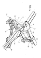
- Figure 4 is a perspective view of the automotive suspension of Figures 1-3; and
- Figure 5 is a further perspective view.
Claims (6)
- An automotive suspension, comprising:characterized in that said rotational shock-absorber (5) has its axis of oscillation (16) coinciding with the axis of oscillation of the first end of the oscillating arm, in that the aforesaid oscillating piston is connected to the structure of the motor vehicle, and in that the casing of said shock-absorber constitutes the aforesaid oscillating arm.an oscillating connection arm (5), which has a first end pivotally connected to the structure of the motor vehicle and the second end pivotally connected to a wheel support;a rotational shock-absorber, which is operatively connected to said oscillating arm and has a casing; andan oscillating-piston element, which is set within a cavity of the casing (14) and defines in said cavity a first chamber (19) and a second chamber (20), which exchange with one another a fluid through a restricted passage provided on said oscillating piston (21),
- The suspension according to Claim 1, characterized in that said suspension comprises a top oscillating arm and a bottom oscillating arm, which are arranged transversely with respect to the longitudinal direction of the motor vehicle for providing oscillating connection of the wheel support to the structure of the motor vehicle, and in that the casing of said rotational shock-absorber constitutes the aforesaid top oscillating arm (5).
- The suspension according to Claim 2, characterized in that the aforesaid oscillating piston (21) is carried by a shaft (23), which turns within the casing (17) of the rotational shock-absorber (5), said shaft (23) being connected, at at least one end, to a support (24), which is rigidly connected to the structure of the motor vehicle.
- The suspension according to Claim 3, characterized in that said shaft (23) is connected to said support (24) by means of an elastic vibration-damping bushing (27).
- The suspension according to Claim 1, characterized in that it comprises elastic means in the form of a leaf spring (29), set transversely with respect to the longitudinal direction of the motor vehicle, anchored centrally to the structure of the motor vehicle, and having each of its ends connected to the casing of the respective rotational shock-absorber (5).
- The suspension according to any one of the preceding claims, characterized in that said rotational shock-absorber uses a magneto-rheological or electrorheological fluid, and in that said piston is provided with electrical-control means for varying the properties of the fluid.
The foregoing substantially as described and illustrated herein and for the purposes specified.
Applications Claiming Priority (2)
| Application Number | Priority Date | Filing Date | Title |
|---|---|---|---|
| IT2002TO000595A ITTO20020595A1 (en) | 2002-07-09 | 2002-07-09 | MOTOR VEHICLE SUSPENSION WITH ROTATIONAL SHOCK ABSORBER |
| ITTO20020595 | 2002-07-09 |
Publications (3)
| Publication Number | Publication Date |
|---|---|
| EP1380768A2 true EP1380768A2 (en) | 2004-01-14 |
| EP1380768A3 EP1380768A3 (en) | 2004-08-18 |
| EP1380768B1 EP1380768B1 (en) | 2006-06-28 |
Family
ID=11459476
Family Applications (1)
| Application Number | Title | Priority Date | Filing Date |
|---|---|---|---|
| EP03010563A Expired - Lifetime EP1380768B1 (en) | 2002-07-09 | 2003-05-12 | Rotating damper for a vehicle suspension |
Country Status (6)
| Country | Link |
|---|---|
| US (1) | US6907968B2 (en) |
| EP (1) | EP1380768B1 (en) |
| AT (1) | ATE331905T1 (en) |
| DE (1) | DE60306462T2 (en) |
| ES (1) | ES2266679T3 (en) |
| IT (1) | ITTO20020595A1 (en) |
Cited By (4)
| Publication number | Priority date | Publication date | Assignee | Title |
|---|---|---|---|---|
| EP1724186A1 (en) | 2005-05-18 | 2006-11-22 | C.R.F. Societa' Consortile per Azioni | Suspension system for a truck cab |
| WO2011050895A1 (en) * | 2009-10-30 | 2011-05-05 | Audi Ag | Wheel suspension for motor vehicles |
| CN104057795A (en) * | 2013-03-20 | 2014-09-24 | 上海同捷科技股份有限公司 | Automotive double-wishbone independent suspension mechanism |
| WO2017016629A1 (en) * | 2015-07-25 | 2017-02-02 | Daimler Ag | Bearing device for supporting a driver's cab on a frame of a utility vehicle |
Families Citing this family (5)
| Publication number | Priority date | Publication date | Assignee | Title |
|---|---|---|---|---|
| ITTO20030907A1 (en) * | 2003-11-14 | 2005-05-15 | Fiat Ricerche | CONTROLLED OSCILLATING DAMPER. |
| US20080142320A1 (en) * | 2006-12-13 | 2008-06-19 | Moradian Norick B | Toroidal rotary damper apparatus |
| WO2008108731A1 (en) * | 2007-03-05 | 2008-09-12 | öHLINS RACING AB | Steering damper and device for mounting a steering damper |
| US8424656B2 (en) * | 2007-06-15 | 2013-04-23 | Techno-Sciences, Inc. | Rotary vane magnetorheological (MR) energy absorber |
| GR20110100739A (en) * | 2011-12-29 | 2013-07-11 | Δημητριος Αθανασιου Χατζηκακιδης | Chamber arrangement of a vehicle's co-axial tosrion bar damper |
Citations (2)
| Publication number | Priority date | Publication date | Assignee | Title |
|---|---|---|---|---|
| EP1070872A1 (en) | 1999-07-20 | 2001-01-24 | C.R.F. Società Consortile per Azioni | Controlled oscillating damper |
| EP1134100A2 (en) | 2000-03-17 | 2001-09-19 | C.R.F. Società Consortile per Azioni | Suspension system including rotary damper means |
Family Cites Families (10)
| Publication number | Priority date | Publication date | Assignee | Title |
|---|---|---|---|---|
| US2005750A (en) * | 1933-04-29 | 1935-06-25 | Houde Eng Corp | Hydraulic shock absorber |
| US2086236A (en) * | 1936-01-17 | 1937-07-06 | Houde Eng Corp | Valving assembly for hydraulic shock absorbers |
| US2496906A (en) * | 1947-07-16 | 1950-02-07 | Studebaker Corp | Spring suspension for vehicles |
| US3326544A (en) * | 1965-03-29 | 1967-06-20 | Stuyvesant C Smith | Shock absorber for vehicles |
| SE8406018D0 (en) * | 1984-11-28 | 1984-11-28 | Hakan Albertsson | HYDRAULDEMPANORDNING |
| DE4015777C2 (en) * | 1989-05-19 | 1997-12-04 | Honda Motor Co Ltd | Suspension device with a rotary damper |
| WO1994006672A1 (en) * | 1992-09-18 | 1994-03-31 | Klein Bicycle Corporation | A high efficiency bicycle suspension |
| US5927740A (en) * | 1996-08-14 | 1999-07-27 | Hopey; Timothy C. | Steering damper in and for vehicles |
| DE19700422C2 (en) * | 1997-01-09 | 2003-12-24 | Zf Sachs Ag | torsional vibration dampers |
| SE523493C2 (en) * | 1997-09-30 | 2004-04-20 | Oehlins Racing Ab | Method of manufacture and arrangement of wing dampers |
-
2002
- 2002-07-09 IT IT2002TO000595A patent/ITTO20020595A1/en unknown
-
2003
- 2003-05-12 ES ES03010563T patent/ES2266679T3/en not_active Expired - Lifetime
- 2003-05-12 EP EP03010563A patent/EP1380768B1/en not_active Expired - Lifetime
- 2003-05-12 DE DE60306462T patent/DE60306462T2/en not_active Expired - Lifetime
- 2003-05-12 AT AT03010563T patent/ATE331905T1/en not_active IP Right Cessation
- 2003-06-02 US US10/449,591 patent/US6907968B2/en not_active Expired - Fee Related
Patent Citations (2)
| Publication number | Priority date | Publication date | Assignee | Title |
|---|---|---|---|---|
| EP1070872A1 (en) | 1999-07-20 | 2001-01-24 | C.R.F. Società Consortile per Azioni | Controlled oscillating damper |
| EP1134100A2 (en) | 2000-03-17 | 2001-09-19 | C.R.F. Società Consortile per Azioni | Suspension system including rotary damper means |
Cited By (7)
| Publication number | Priority date | Publication date | Assignee | Title |
|---|---|---|---|---|
| EP1724186A1 (en) | 2005-05-18 | 2006-11-22 | C.R.F. Societa' Consortile per Azioni | Suspension system for a truck cab |
| US7232180B2 (en) | 2005-05-18 | 2007-06-19 | C.R.F. Società Consortile Per Azioni | Suspension system for a truck cab |
| WO2011050895A1 (en) * | 2009-10-30 | 2011-05-05 | Audi Ag | Wheel suspension for motor vehicles |
| US8573617B2 (en) | 2009-10-30 | 2013-11-05 | Audi Ag | Wheel suspension for motor vehicles |
| CN104057795A (en) * | 2013-03-20 | 2014-09-24 | 上海同捷科技股份有限公司 | Automotive double-wishbone independent suspension mechanism |
| WO2017016629A1 (en) * | 2015-07-25 | 2017-02-02 | Daimler Ag | Bearing device for supporting a driver's cab on a frame of a utility vehicle |
| CN107848580A (en) * | 2015-07-25 | 2018-03-27 | 戴姆勒股份公司 | For the supporting arrangement by cabin mount on the vehicle frame of commercial car |
Also Published As
| Publication number | Publication date |
|---|---|
| DE60306462D1 (en) | 2006-08-10 |
| US6907968B2 (en) | 2005-06-21 |
| EP1380768B1 (en) | 2006-06-28 |
| ITTO20020595A0 (en) | 2002-07-09 |
| US20040007432A1 (en) | 2004-01-15 |
| ATE331905T1 (en) | 2006-07-15 |
| EP1380768A3 (en) | 2004-08-18 |
| ES2266679T3 (en) | 2007-03-01 |
| ITTO20020595A1 (en) | 2004-01-09 |
| DE60306462T2 (en) | 2006-11-23 |
Similar Documents
| Publication | Publication Date | Title |
|---|---|---|
| US7207574B2 (en) | Stabilizer bar with variable torsional stiffness | |
| US5074581A (en) | Vehicle suspension system using a rotary dampen | |
| JP2007513835A (en) | Stabilizer bar with variable torsional rigidity | |
| US4476950A (en) | Drive assembly for vehicle wheel | |
| US6270282B1 (en) | Torque rod apex mount | |
| GB2434128A (en) | Cast apex adjustable V-type torque rod | |
| US6907968B2 (en) | Automotive suspension with a rotational shock-absorber | |
| US7784807B2 (en) | Wheel suspension for motor vehicles | |
| CN110087918A (en) | The adjustable anti-roll stabilizer on the chassis for motor vehicle | |
| JP5625644B2 (en) | Car suspension equipment | |
| JP2006027529A (en) | An electric drive device for a vehicle and an automobile equipped with the same. | |
| CN102666266B (en) | There is the steering anti-kickback snubber of effective adjustment of shock absorbing characteristics | |
| US1971960A (en) | Combined crossbar equalizing and shock absorbing means for vehicles | |
| JPH03200417A (en) | Roll damper | |
| US2950774A (en) | Individual wheel suspension for driven half-axles | |
| JPH0228962Y2 (en) | ||
| KR100616010B1 (en) | Strut assembly of vehicle | |
| JPH02270615A (en) | Suspension using rotary damper | |
| JP7521861B2 (en) | Stabilizer Device | |
| KR20010097155A (en) | Valve structure for shock absorber | |
| KR20130091607A (en) | Rear suspension trailing arm bush apparatus | |
| JPH02270616A (en) | Suspension for steering wheel | |
| KR100471856B1 (en) | Variable stabilizer of vehicles | |
| JPH06227222A (en) | Car suspension | |
| JPH0848122A (en) | Vehicle suspension |
Legal Events
| Date | Code | Title | Description |
|---|---|---|---|
| PUAI | Public reference made under article 153(3) epc to a published international application that has entered the european phase |
Free format text: ORIGINAL CODE: 0009012 |
|
| AK | Designated contracting states |
Kind code of ref document: A2 Designated state(s): AT BE BG CH CY CZ DE DK EE ES FI FR GB GR HU IE IT LI LU MC NL PT RO SE SI SK TR |
|
| AX | Request for extension of the european patent |
Extension state: AL LT LV MK |
|
| PUAL | Search report despatched |
Free format text: ORIGINAL CODE: 0009013 |
|
| AK | Designated contracting states |
Kind code of ref document: A3 Designated state(s): AT BE BG CH CY CZ DE DK EE ES FI FR GB GR HU IE IT LI LU MC NL PT RO SE SI SK TR |
|
| AX | Request for extension of the european patent |
Extension state: AL LT LV MK |
|
| 17P | Request for examination filed |
Effective date: 20041005 |
|
| 17Q | First examination report despatched |
Effective date: 20041229 |
|
| AKX | Designation fees paid |
Designated state(s): AT BE BG CH CY CZ DE DK EE ES FI FR GB GR HU IE IT LI LU MC NL PT RO SE SI SK TR |
|
| GRAP | Despatch of communication of intention to grant a patent |
Free format text: ORIGINAL CODE: EPIDOSNIGR1 |
|
| GRAS | Grant fee paid |
Free format text: ORIGINAL CODE: EPIDOSNIGR3 |
|
| GRAA | (expected) grant |
Free format text: ORIGINAL CODE: 0009210 |
|
| AK | Designated contracting states |
Kind code of ref document: B1 Designated state(s): AT BE BG CH CY CZ DE DK EE ES FI FR GB GR HU IE IT LI LU MC NL PT RO SE SI SK TR |
|
| PG25 | Lapsed in a contracting state [announced via postgrant information from national office to epo] |
Ref country code: IT Free format text: LAPSE BECAUSE OF FAILURE TO SUBMIT A TRANSLATION OF THE DESCRIPTION OR TO PAY THE FEE WITHIN THE PRESCRIBED TIME-LIMIT;WARNING: LAPSES OF ITALIAN PATENTS WITH EFFECTIVE DATE BEFORE 2007 MAY HAVE OCCURRED AT ANY TIME BEFORE 2007. THE CORRECT EFFECTIVE DATE MAY BE DIFFERENT FROM THE ONE RECORDED. Effective date: 20060628 Ref country code: NL Free format text: LAPSE BECAUSE OF FAILURE TO SUBMIT A TRANSLATION OF THE DESCRIPTION OR TO PAY THE FEE WITHIN THE PRESCRIBED TIME-LIMIT Effective date: 20060628 Ref country code: LI Free format text: LAPSE BECAUSE OF FAILURE TO SUBMIT A TRANSLATION OF THE DESCRIPTION OR TO PAY THE FEE WITHIN THE PRESCRIBED TIME-LIMIT Effective date: 20060628 Ref country code: FI Free format text: LAPSE BECAUSE OF FAILURE TO SUBMIT A TRANSLATION OF THE DESCRIPTION OR TO PAY THE FEE WITHIN THE PRESCRIBED TIME-LIMIT Effective date: 20060628 Ref country code: AT Free format text: LAPSE BECAUSE OF FAILURE TO SUBMIT A TRANSLATION OF THE DESCRIPTION OR TO PAY THE FEE WITHIN THE PRESCRIBED TIME-LIMIT Effective date: 20060628 Ref country code: CZ Free format text: LAPSE BECAUSE OF FAILURE TO SUBMIT A TRANSLATION OF THE DESCRIPTION OR TO PAY THE FEE WITHIN THE PRESCRIBED TIME-LIMIT Effective date: 20060628 Ref country code: SI Free format text: LAPSE BECAUSE OF FAILURE TO SUBMIT A TRANSLATION OF THE DESCRIPTION OR TO PAY THE FEE WITHIN THE PRESCRIBED TIME-LIMIT Effective date: 20060628 Ref country code: RO Free format text: LAPSE BECAUSE OF FAILURE TO SUBMIT A TRANSLATION OF THE DESCRIPTION OR TO PAY THE FEE WITHIN THE PRESCRIBED TIME-LIMIT Effective date: 20060628 Ref country code: BE Free format text: LAPSE BECAUSE OF FAILURE TO SUBMIT A TRANSLATION OF THE DESCRIPTION OR TO PAY THE FEE WITHIN THE PRESCRIBED TIME-LIMIT Effective date: 20060628 Ref country code: CH Free format text: LAPSE BECAUSE OF FAILURE TO SUBMIT A TRANSLATION OF THE DESCRIPTION OR TO PAY THE FEE WITHIN THE PRESCRIBED TIME-LIMIT Effective date: 20060628 Ref country code: SK Free format text: LAPSE BECAUSE OF FAILURE TO SUBMIT A TRANSLATION OF THE DESCRIPTION OR TO PAY THE FEE WITHIN THE PRESCRIBED TIME-LIMIT Effective date: 20060628 |
|
| REG | Reference to a national code |
Ref country code: GB Ref legal event code: FG4D |
|
| REG | Reference to a national code |
Ref country code: CH Ref legal event code: EP |
|
| REG | Reference to a national code |
Ref country code: IE Ref legal event code: FG4D |
|
| REF | Corresponds to: |
Ref document number: 60306462 Country of ref document: DE Date of ref document: 20060810 Kind code of ref document: P |
|
| PG25 | Lapsed in a contracting state [announced via postgrant information from national office to epo] |
Ref country code: DK Free format text: LAPSE BECAUSE OF FAILURE TO SUBMIT A TRANSLATION OF THE DESCRIPTION OR TO PAY THE FEE WITHIN THE PRESCRIBED TIME-LIMIT Effective date: 20060928 |
|
| REG | Reference to a national code |
Ref country code: SE Ref legal event code: TRGR |
|
| PG25 | Lapsed in a contracting state [announced via postgrant information from national office to epo] |
Ref country code: PT Free format text: LAPSE BECAUSE OF FAILURE TO SUBMIT A TRANSLATION OF THE DESCRIPTION OR TO PAY THE FEE WITHIN THE PRESCRIBED TIME-LIMIT Effective date: 20061128 |
|
| NLV1 | Nl: lapsed or annulled due to failure to fulfill the requirements of art. 29p and 29m of the patents act | ||
| ET | Fr: translation filed | ||
| REG | Reference to a national code |
Ref country code: CH Ref legal event code: PL |
|
| REG | Reference to a national code |
Ref country code: ES Ref legal event code: FG2A Ref document number: 2266679 Country of ref document: ES Kind code of ref document: T3 |
|
| PLBE | No opposition filed within time limit |
Free format text: ORIGINAL CODE: 0009261 |
|
| STAA | Information on the status of an ep patent application or granted ep patent |
Free format text: STATUS: NO OPPOSITION FILED WITHIN TIME LIMIT |
|
| PGFP | Annual fee paid to national office [announced via postgrant information from national office to epo] |
Ref country code: SE Payment date: 20070508 Year of fee payment: 5 |
|
| 26N | No opposition filed |
Effective date: 20070329 |
|
| PGFP | Annual fee paid to national office [announced via postgrant information from national office to epo] |
Ref country code: ES Payment date: 20070621 Year of fee payment: 5 |
|
| PGFP | Annual fee paid to national office [announced via postgrant information from national office to epo] |
Ref country code: GB Payment date: 20070509 Year of fee payment: 5 |
|
| PG25 | Lapsed in a contracting state [announced via postgrant information from national office to epo] |
Ref country code: MC Free format text: LAPSE BECAUSE OF NON-PAYMENT OF DUE FEES Effective date: 20070531 |
|
| PG25 | Lapsed in a contracting state [announced via postgrant information from national office to epo] |
Ref country code: GR Free format text: LAPSE BECAUSE OF FAILURE TO SUBMIT A TRANSLATION OF THE DESCRIPTION OR TO PAY THE FEE WITHIN THE PRESCRIBED TIME-LIMIT Effective date: 20060929 |
|
| PG25 | Lapsed in a contracting state [announced via postgrant information from national office to epo] |
Ref country code: IE Free format text: LAPSE BECAUSE OF NON-PAYMENT OF DUE FEES Effective date: 20070514 |
|
| PG25 | Lapsed in a contracting state [announced via postgrant information from national office to epo] |
Ref country code: BG Free format text: LAPSE BECAUSE OF FAILURE TO SUBMIT A TRANSLATION OF THE DESCRIPTION OR TO PAY THE FEE WITHIN THE PRESCRIBED TIME-LIMIT Effective date: 20060928 |
|
| PG25 | Lapsed in a contracting state [announced via postgrant information from national office to epo] |
Ref country code: EE Free format text: LAPSE BECAUSE OF FAILURE TO SUBMIT A TRANSLATION OF THE DESCRIPTION OR TO PAY THE FEE WITHIN THE PRESCRIBED TIME-LIMIT Effective date: 20060628 |
|
| GBPC | Gb: european patent ceased through non-payment of renewal fee |
Effective date: 20080512 |
|
| PG25 | Lapsed in a contracting state [announced via postgrant information from national office to epo] |
Ref country code: GB Free format text: LAPSE BECAUSE OF NON-PAYMENT OF DUE FEES Effective date: 20080512 |
|
| REG | Reference to a national code |
Ref country code: ES Ref legal event code: FD2A Effective date: 20080513 |
|
| PG25 | Lapsed in a contracting state [announced via postgrant information from national office to epo] |
Ref country code: CY Free format text: LAPSE BECAUSE OF FAILURE TO SUBMIT A TRANSLATION OF THE DESCRIPTION OR TO PAY THE FEE WITHIN THE PRESCRIBED TIME-LIMIT Effective date: 20060628 Ref country code: LU Free format text: LAPSE BECAUSE OF NON-PAYMENT OF DUE FEES Effective date: 20070512 |
|
| PG25 | Lapsed in a contracting state [announced via postgrant information from national office to epo] |
Ref country code: TR Free format text: LAPSE BECAUSE OF FAILURE TO SUBMIT A TRANSLATION OF THE DESCRIPTION OR TO PAY THE FEE WITHIN THE PRESCRIBED TIME-LIMIT Effective date: 20060628 Ref country code: HU Free format text: LAPSE BECAUSE OF FAILURE TO SUBMIT A TRANSLATION OF THE DESCRIPTION OR TO PAY THE FEE WITHIN THE PRESCRIBED TIME-LIMIT Effective date: 20061229 |
|
| PG25 | Lapsed in a contracting state [announced via postgrant information from national office to epo] |
Ref country code: ES Free format text: LAPSE BECAUSE OF NON-PAYMENT OF DUE FEES Effective date: 20080513 |
|
| PG25 | Lapsed in a contracting state [announced via postgrant information from national office to epo] |
Ref country code: SE Free format text: LAPSE BECAUSE OF NON-PAYMENT OF DUE FEES Effective date: 20080513 |
|
| PG25 | Lapsed in a contracting state [announced via postgrant information from national office to epo] |
Ref country code: IT Free format text: LAPSE BECAUSE OF NON-PAYMENT OF DUE FEES Effective date: 20090512 |
|
| PGRI | Patent reinstated in contracting state [announced from national office to epo] |
Ref country code: IT Effective date: 20110616 |
|
| REG | Reference to a national code |
Ref country code: FR Ref legal event code: PLFP Year of fee payment: 13 |
|
| PGFP | Annual fee paid to national office [announced via postgrant information from national office to epo] |
Ref country code: DE Payment date: 20150506 Year of fee payment: 13 |
|
| PGFP | Annual fee paid to national office [announced via postgrant information from national office to epo] |
Ref country code: IT Payment date: 20150504 Year of fee payment: 13 Ref country code: FR Payment date: 20150508 Year of fee payment: 13 |
|
| REG | Reference to a national code |
Ref country code: DE Ref legal event code: R119 Ref document number: 60306462 Country of ref document: DE |
|
| PG25 | Lapsed in a contracting state [announced via postgrant information from national office to epo] |
Ref country code: IT Free format text: LAPSE BECAUSE OF NON-PAYMENT OF DUE FEES Effective date: 20160512 |
|
| REG | Reference to a national code |
Ref country code: FR Ref legal event code: ST Effective date: 20170131 |
|
| PG25 | Lapsed in a contracting state [announced via postgrant information from national office to epo] |
Ref country code: DE Free format text: LAPSE BECAUSE OF NON-PAYMENT OF DUE FEES Effective date: 20161201 Ref country code: FR Free format text: LAPSE BECAUSE OF NON-PAYMENT OF DUE FEES Effective date: 20160531 |