EP1380754B1 - Trochoidal pump - Google Patents
Trochoidal pump Download PDFInfo
- Publication number
- EP1380754B1 EP1380754B1 EP03254305A EP03254305A EP1380754B1 EP 1380754 B1 EP1380754 B1 EP 1380754B1 EP 03254305 A EP03254305 A EP 03254305A EP 03254305 A EP03254305 A EP 03254305A EP 1380754 B1 EP1380754 B1 EP 1380754B1
- Authority
- EP
- European Patent Office
- Prior art keywords
- clearance
- tooth
- inner rotor
- clearances
- rotor
- Prior art date
- Legal status (The legal status is an assumption and is not a legal conclusion. Google has not performed a legal analysis and makes no representation as to the accuracy of the status listed.)
- Expired - Lifetime
Links
Images




Classifications
-
- F—MECHANICAL ENGINEERING; LIGHTING; HEATING; WEAPONS; BLASTING
- F04—POSITIVE - DISPLACEMENT MACHINES FOR LIQUIDS; PUMPS FOR LIQUIDS OR ELASTIC FLUIDS
- F04C—ROTARY-PISTON, OR OSCILLATING-PISTON, POSITIVE-DISPLACEMENT MACHINES FOR LIQUIDS; ROTARY-PISTON, OR OSCILLATING-PISTON, POSITIVE-DISPLACEMENT PUMPS
- F04C15/00—Component parts, details or accessories of machines, pumps or pumping installations, not provided for in groups F04C2/00 - F04C14/00
- F04C15/0042—Systems for the equilibration of forces acting on the machines or pump
- F04C15/0049—Equalization of pressure pulses
-
- F—MECHANICAL ENGINEERING; LIGHTING; HEATING; WEAPONS; BLASTING
- F04—POSITIVE - DISPLACEMENT MACHINES FOR LIQUIDS; PUMPS FOR LIQUIDS OR ELASTIC FLUIDS
- F04C—ROTARY-PISTON, OR OSCILLATING-PISTON, POSITIVE-DISPLACEMENT MACHINES FOR LIQUIDS; ROTARY-PISTON, OR OSCILLATING-PISTON, POSITIVE-DISPLACEMENT PUMPS
- F04C2/00—Rotary-piston machines or pumps
- F04C2/08—Rotary-piston machines or pumps of intermeshing-engagement type, i.e. with engagement of co-operating members similar to that of toothed gearing
- F04C2/082—Details specially related to intermeshing engagement type machines or pumps
- F04C2/084—Toothed wheels
-
- F—MECHANICAL ENGINEERING; LIGHTING; HEATING; WEAPONS; BLASTING
- F04—POSITIVE - DISPLACEMENT MACHINES FOR LIQUIDS; PUMPS FOR LIQUIDS OR ELASTIC FLUIDS
- F04C—ROTARY-PISTON, OR OSCILLATING-PISTON, POSITIVE-DISPLACEMENT MACHINES FOR LIQUIDS; ROTARY-PISTON, OR OSCILLATING-PISTON, POSITIVE-DISPLACEMENT PUMPS
- F04C2/00—Rotary-piston machines or pumps
- F04C2/08—Rotary-piston machines or pumps of intermeshing-engagement type, i.e. with engagement of co-operating members similar to that of toothed gearing
- F04C2/10—Rotary-piston machines or pumps of intermeshing-engagement type, i.e. with engagement of co-operating members similar to that of toothed gearing of internal-axis type with the outer member having more teeth or tooth-equivalents, e.g. rollers, than the inner member
- F04C2/102—Rotary-piston machines or pumps of intermeshing-engagement type, i.e. with engagement of co-operating members similar to that of toothed gearing of internal-axis type with the outer member having more teeth or tooth-equivalents, e.g. rollers, than the inner member the two members rotating simultaneously around their respective axes
Definitions
- the present invention relates to a trochoidal pump comprising an inner rotor and an outer rotor having a trochoidal toothed shape, wherein noise caused by pulsation generated when a fluid is discharged can be reduced.
- a trochoidal pump is widely used as a lubricating oil pump fitted in an automobile engine, or the like.
- This trochoidal pump is fitted with an inner rotor and an outer rotor having a trochoidal toothed shape.
- JP Utility Model No. (Sho)64-56589 discloses a trochoidal pump of this kind, having a composition wherein the rear side face of each tooth of the inner rotor in the direction of rotation is formed into a simple arc about a single central point, and the height of this section is made lower than the tooth shape based on the trochoidal curve.
- Japanese Patent Laid-open No. (Hei)2-95787 discloses a pump wherein the faces of the tips of the inner teeth of the outer rotor and the outer teeth of the inner rotor are formed so as to follow a partial circumference of a circular cylinder drawn about the centre of rotation of the respective rotor, the interval between the front ends of the teeth of the inner rotor and the outer rotor, in other words, the tip clearance, which has an effect on the sealing properties, being maintained at a prescribed value, whilst the front faces of the rotor teeth are adjusted.
- the two foregoing patents specify the shape of the teeth in such a manner that a prescribed tip clearance is set, equally for each of the teeth.
- the foregoing disclosures propose devices wherein the shape of the teeth is changed in order to set a prescribed tip clearance equally for each of the teeth, thereby reducing the pulsation of the fluid, reducing the noise, and also increasing the pump performance.
- the noise is certainly restricted by reduction of fluid pulsation, in reducing the pulsation, the state where the fluid is enclosed in the spaces between the inner rotor and outer rotor is eliminated, and furthermore, it becomes necessary to provide a tip clearance between the ends of the teeth of the inner rotor and the outer rotor, in such a manner that the fluid can be introduced into the spaces and expelled therefrom, smoothly and readily.
- this tip clearance By setting this tip clearance to a suitable value, it is possible to reduce pulsation and hence to reduce noise. However, increasing the tip clearance simultaneously produces a drawback in that pump performance declines. Moreover, if the tip clearance is set to a small value in order to maintain pump performance, it then becomes difficult to reduce pulsation and noise.
- trochoidal pumps are disclosed in US-A-5368455 and US-A-5030072.
- a variation in tip clearance is provided between the inner and outer rotors but in such a way that a hydraulic pulsation still occurs with corresponding noise being generated.
- the prior art technology sets the same prescribed tip clearance equally for each of the respective teeth, and therefore the setting of the tip clearance is important, but since this tip clearance is set uniformly at the respective teeth of the inner rotor and outer rotor when the pump rotates, a systematic pulsation is generated by the uniformly established tip clearances.
- the object of the present invention lies in reducing pulsation of this kind whilst at the same time maintaining pump efficiency at a uniform level.
- a trochoidal pump comprises an inner rotor and an outer rotor having trochoidal toothed shapes provided in a mutually intermeshing state, in such a manner that a normal tip clearance is created between a first number of tooth crests of the inner rotor and the outer rotor characterised in that one or more second tooth crests of one or both of the inner and outer rotors is formed with a tip displaced radially with respect to the first tooth crests of the corresponding rotor so as to define a larger tip clearance than the normal tip clearance.
- the trochoidal pump according to the present invention comprises an inner rotor 5 and an outer rotor 6 having a trochoidal toothed shape installed in a rotor chamber 1 formed inside a casing, similarly to a general trochoidal pump.
- the rotor chamber 1 is formed with an intake port 2 and an outlet port 3 extending in the circumferential direction in the vicinity of the outer circumference.
- the intake port 2 and the outlet port 3 are formed in laterally symmetrical positions about the centre of the rotor chamber 1.
- the inner rotor 5 has a number of teeth one fewer than the outer rotor 6, and a relationship is formed whereby each time the inner rotor 5 performs one whole revolution, the outer rotor 6 rotates with a delay equivalent to one tooth behind the inner rotor.
- the inner rotor 5 comprises tooth crests 5a which project in an outward direction and concave shaped tooth valleys 5b
- the outer rotor 6 comprises tooth crests 6a which project towards the centre from the inner circumference thereof, and concave shaped tooth valleys 6b.
- the inner rotor 5 and outer rotor 6 always intermesh at one point, tooth crests 5a of the inner rotor 5 being introduced into tooth valleys 6b of the outer rotor 6 and tooth crests 6a of the outer rotor 6 being introduced into tooth valleys 5b of the inner rotor 5.
- a plurality of demarcated spaces s, s, ⁇ are formed between the inner rotor 5 and the outer rotor 6 when they are operated, and by means of the rotating inner rotor 5 and outer rotor 6, fluid is taken in via the intake port 2 whilst the spaces on the input port 2 side gradually increase in volume, and furthermore, fluid is expelled from the outlet port 3 whilst the spaces s on the outlet port 3 side gradually decrease in volume.
- a clearance which is greater than the normally set tip clearance d 0 in other words, a large clearance d 1 , is set as illustrated in Fig. 1 and Fig. 2.
- the tooth crests for achieving this large clearance d 1 are formed on either the outer rotor 6 or the inner rotor 5.
- a large clearance tip 5a 1 is formed on a suitable one or plurality of the crest ends of the plurality of tooth crests 5a of the inner rotor 5.
- a large clearance tip 6a 1 is formed on a suitable one or plurality of the crest ends of the plurality of tooth crests 6a of the outer rotor 6.
- the tooth shape of the large clearance tips 5a 1 , 6a 1 is achieved by processing for removing the front end of the tooth crest, or forming a tooth shape having a low front end on the tooth crest when forming the rotor, or the like.
- the generally established tip clearance d 0 is set uniformly, and by providing a tooth crest set especially to a large clearance d 1 in the rotor teeth, the tip clearance d 0 of the intermeshing rotors becomes non-uniform.
- the tooth crests are set in such a manner that a large clearance d 1 is provided in two places on an inner rotor 5 having four teeth, then the large clearance is provided every other tooth and there will be tooth crests having the normally established tip clearance of d 0 between these tooth crests.
- tooth crests having a large clearance d 1 are provided in two places in an inner rotor having six teeth, then they will be provided at intervals of three teeth, or an intervals of two teeth and fourth teeth.
- the tooth crests set to have a large tip clearance d 0 are set at least every other tooth position, and hence there will be tooth crests having a large tip clearance d 0 set every other tooth position, or at intervals of one teeth and three teeth, as described previously, depending on the number of such teeth set.
- a tooth crest having a large clearance d 1 should be set in at least one position, but desirably a suitable number of such tooth crests are provided, according to the number of teeth on the rotors. Setting a large clearance d 1 on a rotor having six teeth or more is desirable, since it allows pulsation to be suppressed without reducing volume efficiency.
- Tooth crests having an enlarged clearance d 1 make it possible to reduce the number of enclosed space volumes by interconnecting the spatial volumes formed between the intermeshing rotors, thus reducing pulsation, and hence pulsation can be suppressed to a low value. Furthermore, any reduction in volume efficiency caused by interconnection of the spatial volume between the rotors can be restricted by designing the rotors to have six or more teeth. In other words, adjacent spaces s, s are interconnected by means of the large clearance d 1 , thereby permitting the passage of fluid and preventing enclosure of the fluid.
- a number of tooth crests equal to n/2 are set to have a large clearance d 1 .
- the tooth crests formed with a large clearance d 1 are set at the least every other tooth. If the number of teeth n is even, then by setting the number of tooth crests formed with a large clearance d 1 to n/2, it is possible to a well balanced arrangement, and pulsation can be suppressed whilst maintaining volume efficiency.
- the inner rotor 5 or outer rotor 6 has an odd number of teeth
- a number of tooth crests (n-1)/2 are set to have a large clearance d 1 , these being disposed at the least every other tooth, similarly to the foregoing description.
- the ratio of the number of tooth crests having a standard tip clearance d 0 is set to a larger ratio, and furthermore, the tooth crests formed with a large clearance d 1 are not arranged equidistantly.
- the tip clearance d 0 of the rotors ceases to be uniform, and assumes a non-uniform state.
- the large clearance d 1 moves in accordance with the meshing rotation of the outer rotor 6 and inner rotor 5, thereby changing phase. If the number of large clearances d 1 is more than one, then the positioning thereof may be uniform or non-uniform with respect to the number of rotor teeth, or it may be non-uniform, regardless of the number of rotor teeth.
- the regularity of the hydraulic pulsation of the pump is disturbed, thus making it possible to prevent resonance due to pulsation and to reduce noise.
- This is now described on the basis of a graph illustrating this effect.
- the value of the hydraulic pulsation plotted on the Y axis is as shown in the graph, the units being decibels (dB).
- the graph relates to a rotational speed of 2000 rpm.
- the waveform of the graph is achieved by measuring the frequency of the hydraulic pulsation (the resonance speed).
- the standard value graph shows data for a normal trochoidal type oil pump.
- the frequency of the hydraulic pulsations in this graph is determined by the rotational speed of the pump and the number of teeth of the rotors.
- the pump speed is 2000 rpm
- the number of teeth n of the inner rotor 5 is 6
- the number of teeth n of the outer rotor 6 is 7, and the graph shows the frequency generated by these rotors.
- graphs are illustrated for a pump having a standard tip clearance d 0 (standard value) (see Fig. 10), a pump wherein the large clearance d 1 is set in two places (on two teeth) (see Fig. 8), and a pump wherein the large clearance d 1 is set in three places (three teeth) (see Fig. 9), each graph depicting the corresponding state of the hydraulic pulsation.
- the standard value (STD) graph has a waveform of regular pulsations.
- the graphs for pumps having a large clearance d 1 on two teeth and three teeth each show a significant variation in waveform compared to the standard value.
- the variation in waveforms also differs according to the three toothed arrangement wherein a large clearance d 1 is provided every other tooth or the two toothed arrangement wherein it is provided every three teeth.
- the pumps provided with tooth crests formed with large clearances d 1 on two or three teeth achieve a reduction with respect to the oscillation at 324 Hz which is indicated as a frequency where a strong hydraulic pulsation is obtained in the standard value.
- the pulsation is stronger at a lower frequency than 324 Hz.
- Both the two and three tooth versions have a maximum pulsation at some 175 Hz lower than the standard value.
- the tooth crests 5a formed with a large clearance d 1 are tooth crests 5a which have a large clearance d 1 compared to the tooth crests 5a having a standard tip clearance d 0 .
- the standard tip clearance d 0 is the clearance required to achieve a rotational sliding motion whilst respectively sealing the volume spaces created by the intermeshing of the outer rotor 6 and inner rotor 5.
- the large clearance d 1 is set appropriately to value whereby two volume spaces are connected.
- the characteristics of the graph in Fig. 10 illustrating the standard value comprising a standard tip clearance d 0 only are such that a regular pointed waveform is created.
- This waveform is shown in first, second and third order sections in the graph.
- the pointed waveform is such that only the particular frequency projects significantly.
- the graph shows hydraulic pulsation (oscillation), but if this pulsation causes resonance with the oil filter, and the like, via the piping of the pump, thus appearing as sound, then this sound will be a particular sound having the particular frequency which projects in the graph, and it will be heard continually, thus creating an annoying noise.
- the graph for the two tooth non-uniform composition shows the waveform in a case where the rotational speed is maintained at a uniform 2000 rpm and the tip clearance d 0 in two of the six tooth crests of the inner rotor 5 is increased to a large clearance of d in a rotor of the standard value (STD) described above.
- the waveform wherein a particular frequency projects in a peaked shape is reduced in comparison with the standard value.
- the frequencies surrounding the first, second and third-order frequencies are also increased, and the projecting state of a particular frequency is eased (see corresponding portions of the graphs). Since a sound is generated at a particular frequency in the standard value design, this sound is readily audible and creates a bothersome noise.
- the surrounding frequencies are also increased, and hence a variety of sounds are combined together, forming a diverse sound which is not readily audible. As a result, the noise is reduced.
- the inner rotor 5 and outer rotor 6 support each other mutually at contact point t caused by the intermeshing of the respective tooth crests of the inner rotor 5 and the outer rotor 6, and hence play in the radial direction of the rotors can be prevented. Thereby, pulsation becomes less liable to occur and a stable rotational state can be achieved.
- the mutual support between the inner rotor 5 and the outer rotor 6 due to the standard tip clearance d 0 is also performed in the region outside the scope of the intake port 2, as illustrated in Fig.7(C).
- the plurality of large clearances d 1 , d 1 , ⁇ are arranged uniformly. For example, as shown in Fig. 15(A), if the number of teeth in the inner rotor 5 is eight, then large clearance tips 5a 1 on tooth crests 5a formed with a large clearance d 1 are provided every other tooth.
- this plurality of large clearances d 1 , d 1 , ⁇ are arranged in a non-uniform fashion.
- the inner rotor 5 has eight teeth, similarly to the first pattern, then as shown in Fig. 15(B), after a first large clearance tip 5a 1 where a tooth crest 5a is formed with a large clearance d 1 , the next large clearance tip 5a 1 is formed at a spacing of three teeth. Thereupon, the next large clearance tip 5a 1 is formed at a further spacing of two teeth.
- Fig. 15(B) after a first large clearance tip 5a 1 where a tooth crest 5a is formed with a large clearance d 1 , the next large clearance tip 5a 1 is formed at a spacing of three teeth. Thereupon, the next large clearance tip 5a 1 is formed at a further spacing of two teeth.
- the next large clearance tip 5a 1 may be formed at a spacing of two teeth. Thereupon, the next large clearance tip 5a 1 is formed at a further spacing of four teeth.
- the large clearance tips 5a 1 where tooth crests 5a are provided with a large clearance d 1 are formed appropriately, in such a manner that there is no regularity in the positioning of the large clearance tips 5a 1 , 5a 1 , ⁇ forming the large clearances d 1 , d 1 , ⁇ .
- This non-uniform arrangement of the large clearances d 1 , d 1 , ⁇ is also performed if the inner rotor 5 has an odd number of teeth.
- the large clearance d 1 in the position of region (A) in Fig. 16 is taken to be the same large clearance d 1 as the large clearances d 1 in the positions of regions (B) and (C).
- a space s is formed between the inner rotor 5 and outer rotor 6, if the minimum space between the tooth crest 5a of the inner rotor 5 and the tooth crest 6a of the outer rotor 6 enclosing the space s is greater than the standard tip clearance d 0 , then this is taken as a large clearance d 1 .
- region (A), region (B) and region (C) illustrated in Fig. 16 are mixed together appropriately, and they are distributed in a uniform or non-uniform manner.
- the interval dimensions of the plurality of large clearances d 1 , d 1 , ⁇ there are the following plurality of patterns.
- the interval dimensions of all of the large clearances d 1 , d 1 , ⁇ formed are taken to be the same.
- the respective large clearances d 1 ,d 1 , ⁇ at region (A), region (B) and region (C) in Fig. 16 all have the mutually equal interval dimensions, as described previously.
- the fluid interconnected between the spaces s via the large clearance d 1 is the same in each of the locations of the large clearances d 1 , d 1 , ⁇ . Consequently, the non-regularity of the pulsation during operation of the pump is generated at two different positions, those of the tip clearance d 0 and the large clearance d 1 , thus producing a simple non-regularity.
- the interval dimensions of all of the large clearances d 11 , d 12 , ⁇ formed are mutually different, and there exist no large clearances d 1 , d 1 , ⁇ which have the same interval dimensions.
- the addition of suffixes to the large clearances d 11 , d 12 , ⁇ makes it easier to distinguish between the respective large clearances d 1 , d 1 , ⁇ , in cases where the interval dimensions thereof are mutually different, as described above.
- the amount of fluid connected between spaces s via the large clearance d 1 is different in each of the respective large clearances d 11 , d 12 , ⁇ .
- the non-regularity of the pulsation during pump operation is generated not only by the tip clearance d 0 and the large clearance d 1 , but also by the plurality of different large clearances d 11 , d 12 , ⁇ . In this second pattern of interval dimensions, the non-regularity of the pulsation is enhanced.
- the interval dimension of at least one large clearance d 1 ' of the plurality of large clearances d 1 , d 1 , ⁇ formed is different from the interval dimensions of the other large clearances d 1 , d 1 , ⁇ .
- the non-regularity of pulsation is approximately midway between that of the first pattern and the second pattern.
- the (') symbol in the large clearance d 1 ' described above is used to distinguish it readily from the other large clearances d 1 , d 1 , ⁇ .
- large clearances d 1 are created by forming large clearance tips 5a 1 on tooth crests 5a of the inner rotor 5, or by forming large clearance tips 6a 1 on the tooth crests 6a of the outer rotor.
- the large clearances d 1 are formed only on large clearance tips 5a 1 on the inner rotor 5 (see Fig. 13), or they are formed only on large clearance tips 6a 1 on the outer rotor 6 (see Fig. 14).
- the large clearances d 1 , d 1 , ⁇ are formed in such a manner that all have the same interval dimensions, as described in the interval dimension patterns for the large clearances d 1 mentioned above.
- the tooth crests 5a are retracted by mutually different amounts, thereby causing the size of a plurality of large clearance tips 5a 11 , 5a 12 , ⁇ to be mutually different, and hence the interval dimensions of all of the large clearances d 11 , d 12 , ⁇ formed are mutually different, as described previously.
- the addition of the suffixes makes it easier to distinguish between a plurality of large clearance tips 5a 1 , 5a 1 , ⁇ each of which has been retracted by a different amount.
- the large clearances d 11 , d 12 , ... were constituted by forming a plurality of large clearance tips 5a 11 , 5a 12 , ⁇ on the inner rotor 5, but it is also possible to set a plurality of large clearance tips 6a 11 , 6a 12 , ⁇ on the outer rotor 6 to mutually different sizes, or to set a suitable one large clearance tip 6a 1 of a plurality of large clearance tips 6a 11 , 6a 12 , ⁇ on the outer rotor 6 to a different size from the other large clearance tips 6a 1 , 6a 1 , ⁇ .
- the addition of suffixes to the large clearance tips 6a 11 , 6a 12 , ⁇ makes it easier to distinguish between the large clearance tips 6a 1 , 6a 1 , ⁇ of mutually different sizes.
- large clearance tips 5a 1 are formed on tooth crests 5a of the inner rotor 5, and furthermore, large clearance tips 6a 1 are formed on the tooth crests 6a of the outer rotor 6.
- the maximum clearance d max has an interval dimension which is greater than the standard large clearance d 1 , in other words, the large clearance d 1 created by the retraction of the circumferential edge of one only of either a tooth crest 5a of the inner rotor 5 or a tooth crest 6a of the outer rotor 6.
- the large clearance d 1 may be formed by means of a large clearance tip 5a 1 on the inner rotor 5 and a large clearance tip 6a 1 on the outer rotor 6.
- the relative magnitudes of the retraction amounts q 1 , q 2 , q 3 are as follows. (6) q 1 > q 2 , (7) q 1 ⁇ q 2 , (8) q 2 > q 3 , (9) q 2 ⁇ q 3 , (10) q 1 > q 3 , (11) q 1 ⁇ q 3 .
- the relative magnitudes of the retraction amounts q 1 , q 2 , q 3 are as follows. (6) q 1 ' > q 2 ', (7) q 1 ' ⁇ q 2 ', (8) q 2 ' > q 3 ', (9) q 2 ' ⁇ q 3 ', (10) q 1 ' > q 3 ', (11) q 1 ' ⁇ q 3 '.
- the maximum clearance d max in the fourth pattern will be of a varying size, whilst the large clearance d 1 in the fifth pattern will be of uniform size.
- the large clearance d 1 in the fifth pattern although the large clearances d 1 created by the combination of rotors will be of uniform size, since the amounts of retraction forming these clearances are different on the inner rotor 5 and the outer rotor 6, the large clearance d 1 greater than the tip clearance d 0 , which is formed when opposing the tooth crest 5a of the inner rotor 5 or the tooth crest 6a of the outer rotor 6, will be of varying size.
- the combinations of maximum clearance d max in the fourth pattern and the respective amounts of retraction in the large clearance d 1 in the fifth pattern are as described below.
- the plurality of large clearances d 1 , d 1 , ⁇ or the maximum clearance d max are constituted by the aforementioned combinations, and the interval dimensions of the respective large clearances d 1 , d 1 , ⁇ based on the respective amounts of retraction described above are respectively different, which means that when the pump operates, since the large clearances d 1 , d 1 , ⁇ each have mutually different interval dimensions, it is possible to generate non-regularity in the pulsing action.
- the invention according to a first claim concerns a trochoidal pump wherein an inner rotor 5 and an outer rotor 6 having trochoidal toothed shapes are provided in a mutually intermeshing state, in such a manner that a tip clearance d 0 is created between each tooth crest 5a of the inner rotor 5 and the outer rotor 6, a large clearance d 1 forming a large interval being provided in at least one location of the group of the tip clearances d 0 , whereby pulsation can be suppressed whilst maintaining volume efficiency.
- the invention according to a second claim concerns the trochoidal pump of the first claim, wherein the number of teeth of the inner rotor 5 is six or more, and a large clearance d 1 is formed between the inner rotor 5 and the outer rotor 6, on the plurality of tooth crests 5a of the inner rotor 5, at least at every other tooth position, whereby, if the inner rotor 5 (or outer rotor 6) has six or more teeth, the positions at which the clearance created between a tooth crest 5 of the inner rotor and the outer rotor 6 becomes a large clearance d 1 are set to be at least every other tooth position of the inner rotor 5, and by selecting the number and arrangement thereof appropriately, a variety of pump performances can be provided readily.
- the large clearances d 1 , d 1 , ⁇ form a tooth shape which does not perform rotational drive of the rotors, since they form an interconnected state during intermeshing of the rotors, they allow a well balanced arrangement of the tip clearances d 0 which maintain rotational drive intermeshing of the rotors, and hence the rotation of the rotors can be stabilized.
- the inner rotor 5 and outer rotor 6 support each other mutually due to intermeshing between the respective tooth crests of the inner rotor 5 and the outer rotor 6, and hence play in the radial direction of the rotors can be prevented, thereby making pulsation becomes less liable to occur and making it possible to achieve a stable rotational state.
- the invention according to the third claim concerns the trochoidal pump according to claims 1 or 2, wherein, taking the number of teeth of the inner rotor 5 or outer rotor 6 as n, large clearances d 2 , d 1 , ⁇ are arranged in a uniform or non-uniform fashion on appropriate tooth crests 5a, 6a of the teeth, whereby the large clearances d 1 , d 1 , ⁇ are arranged in a uniform or non-uniform fashion, and together with the standard tip clearances d 0 , they are able to generate non-regularity in the pulsation caused by the operation of the pump, thus increasing the degree to which resonance can be prevented and noise can be reduced to a low level.
- the invention according to the fourth claim concerns the trochoidal pump according to claim 1, 2 or 3, wherein the number of teeth, n, of the inner rotor 5 is set to an even number, and a large clearance d 1 is provided every other tooth on (n/2) tooth crests, whereby, if the number of teeth, n, of the inner rotor (or the outer rotor 6) is an even number, then the tooth crests forming a large clearance d 1 can be set to be at least in every other tooth position.
- the regions formed with a large clearance d 1 can be set to n/2 regions, and a well-balanced arrangement between the tip clearance d 0 and the large clearance d 1 can be achieved, thus making it possible to suppress pulsation whilst maintaining volume efficiency.
- the invention according to the fifth claim concerns the trochoidal pump according to claim 1, 2 or 3, wherein the number of teeth, n, of the inner rotor 5 is set to an odd number, and a large clearance d 1 is provided at least every other tooth position or every other two tooth positions, on ((n-1)/2) tooth crests, whereby the sequence of the positions of the tip clearances d 0 and large clearances d 1 becomes non-uniform, rather than being systematic, in addition to which the positioning of the tooth crests having large clearance d 1 becomes non-uniform, thereby disturbing the regularity of the hydraulic pulsations, avoiding resonance, and hence making it possible suppress pulsation whilst ensuring volume efficiency.
- the invention according to the sixth claim concerns the trochoidal pump according claim 1, 2, 3, 4 or 5, wherein there are a plurality of the large clearances d 1 , and all of these large clearances d 1 , d 1 , ⁇ have the same interval dimension, whereby a non-regularity in the pulsation caused when the pump operates can be generated by the standard tip clearances d 0 , d 0 , ⁇ and the large clearances d 1 , d 1 , ⁇ , and moreover, since the plurality of large clearances d 1 , d 1 , ⁇ are formed with the same interval dimensions, the composition becomes extremely simple, and the structure of the inner rotor 5 or outer rotor 6 for forming the large clearances d 1 , d 1 , ⁇ can be achieved in a comparatively easy fashion.
- the invention according to the seventh claim concerns the trochoidal pump according to claim 1, 2, 3, 4 or 5, wherein there are a plurality of the large clearances d 1 , and all of these large clearances d 1 , d 1 , ⁇ have mutually different interval dimensions, whereby, in addition to the non-regularity of the pulsation caused by the tip clearances d 0 and the large clearances d 1 , the non-regularity of the pulsation caused when the pump operates is further increased by the non-regularity of the pulsation caused by the plurality of large clearances d 1 , thereby increasing the degree to which resonance can be prevented and noise can be reduced to a low level.
- the invention according to the eighth claim concerns the trochoidal pump according to claim 1, 2, 3, 4, or 5, wherein there are a plurality of the large clearances d 1 , and at least one of all of these large clearances d 1 , d 1 , ⁇ has a different interval dimension to the other large clearances d 1 , whereby, in addition to the non-regularity of the pulsation caused by the tip clearances d 0 and the large clearances d 1 , since at least one large clearance d 1 of the plurality of large clearances d 1 , d 1 , ⁇ has a different interval dimension to the other large clearances d 1 , it is also possible to generate non-regularity in the pulsation by means of the large clearances d 1 , d 1 , ⁇ alone, thus increasing the degree to which resonance can be prevented and the noise can be suppressed to a low level.
- the invention according to the ninth claim concerns the trochoidal pump according to claim 1, 2, 3, 4, 5, 6, 7 or 8, wherein the large clearances d 1 are formed by retracting the circumferential edges of either tooth crests 5a of the inner rotor 5 or tooth crests 6a of the outer rotor 6, whereby the structure can be achieved in an extremely easy fashion, since the circumferential edges of tooth crests of either the inner rotor 5 or outer rotor 6 are retracted.
- the invention according to the tenth claim concerns the trochoidal pump according to claim 1, 2, 3, 4, 5, 6, 7 or 8, wherein the large clearances d 1 are formed by retracting the circumferential edges of both tooth crests 5a of the inner rotor 5 and tooth crests 6a of the outer rotor 6, whereby there will exist large clearances d 1 of the plurality of large clearances d 1 , d 1 , ⁇ , which are formed by a large clearance tip 5a 1 of the inner rotor 5 and a large clearance tip 6a 1 of the outer rotor 6.
- a particularly big large clearance d 1 (in other words, a maximum clearance d max ) will occur amongst the large clearances d 1 , d 1 , ⁇ , and by retracting the tooth crests 5a of the inner rotor 5 and the tooth crests 6a of the outer rotor appropriately, it is possible to provide large clearances d 1 of a variety of sizes, whereby the non-regularity of the pulsation caused by pump operation becomes even more pronounced, thus increasing the degree to which the resonance can be prevented and noise can be reduced to a low level.
- d max q + q'.
Landscapes
- Engineering & Computer Science (AREA)
- Mechanical Engineering (AREA)
- General Engineering & Computer Science (AREA)
- Rotary Pumps (AREA)
- Details And Applications Of Rotary Liquid Pumps (AREA)
Description
- The present invention relates to a trochoidal pump comprising an inner rotor and an outer rotor having a trochoidal toothed shape, wherein noise caused by pulsation generated when a fluid is discharged can be reduced.
- A trochoidal pump is widely used as a lubricating oil pump fitted in an automobile engine, or the like. This trochoidal pump is fitted with an inner rotor and an outer rotor having a trochoidal toothed shape. JP Utility Model No. (Sho)64-56589 discloses a trochoidal pump of this kind, having a composition wherein the rear side face of each tooth of the inner rotor in the direction of rotation is formed into a simple arc about a single central point, and the height of this section is made lower than the tooth shape based on the trochoidal curve.
- Furthermore, Japanese Patent Laid-open No. (Hei)2-95787 discloses a pump wherein the faces of the tips of the inner teeth of the outer rotor and the outer teeth of the inner rotor are formed so as to follow a partial circumference of a circular cylinder drawn about the centre of rotation of the respective rotor, the interval between the front ends of the teeth of the inner rotor and the outer rotor, in other words, the tip clearance, which has an effect on the sealing properties, being maintained at a prescribed value, whilst the front faces of the rotor teeth are adjusted. The two foregoing patents specify the shape of the teeth in such a manner that a prescribed tip clearance is set, equally for each of the teeth.
- The foregoing disclosures propose devices wherein the shape of the teeth is changed in order to set a prescribed tip clearance equally for each of the teeth, thereby reducing the pulsation of the fluid, reducing the noise, and also increasing the pump performance. Although the noise is certainly restricted by reduction of fluid pulsation, in reducing the pulsation, the state where the fluid is enclosed in the spaces between the inner rotor and outer rotor is eliminated, and furthermore, it becomes necessary to provide a tip clearance between the ends of the teeth of the inner rotor and the outer rotor, in such a manner that the fluid can be introduced into the spaces and expelled therefrom, smoothly and readily.
- By setting this tip clearance to a suitable value, it is possible to reduce pulsation and hence to reduce noise. However, increasing the tip clearance simultaneously produces a drawback in that pump performance declines. Moreover, if the tip clearance is set to a small value in order to maintain pump performance, it then becomes difficult to reduce pulsation and noise.
- It is extremely hard to set up optimum conditions whilst resolving these mutually contradictory conditions
- Further examples of trochoidal pumps are disclosed in US-A-5368455 and US-A-5030072. In these examples, a variation in tip clearance is provided between the inner and outer rotors but in such a way that a hydraulic pulsation still occurs with corresponding noise being generated.
- The prior art technology sets the same prescribed tip clearance equally for each of the respective teeth, and therefore the setting of the tip clearance is important, but since this tip clearance is set uniformly at the respective teeth of the inner rotor and outer rotor when the pump rotates, a systematic pulsation is generated by the uniformly established tip clearances. When the pressurized fluid generating this systematic pulsation is discharged from the pump, resonance is liable to occur in both the pump and the fluid supply device, and it becomes difficult to prevent the generation of noise. The object of the present invention lies in reducing pulsation of this kind whilst at the same time maintaining pump efficiency at a uniform level.
- Therefore, as a result of thorough study and research with the aim of resolving these problems, the present inventors devised the present invention.
- In accordance with the present invention a trochoidal pump comprises an inner rotor and an outer rotor having trochoidal toothed shapes provided in a mutually intermeshing state, in such a manner that a normal tip clearance is created between a first number of tooth crests of the inner rotor and the outer rotor characterised in that one or more second tooth crests of one or both of the inner and outer rotors is formed with a tip displaced radially with respect to the first tooth crests of the corresponding rotor so as to define a larger tip clearance than the normal tip clearance.
- Some examples of trochoidal pumps according to the invention will now be described with reference to the accompanying drawings, in which:-
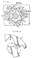
- Fig. 1 is a front view of the present invention,
- Fig. 2 is an enlarged view of section (A) in Fig. 1,
- Fig. 3 is an enlarged view of section (B) in Fig. 1,
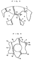
- Fig. 4 is a front view of an inner rotor having an even number of teeth according to the present invention,
- Fig. 5 is a front view of an outer rotor corresponding to the inner rotor in Fig. 4,
- Fig. 6(A) is a front view showing a combined state of an inner rotor having an odd number of teeth and an outer rotor corresponding to this inner rotor and Fig. 6(B) is a front view of an inner rotor having an odd number of teeth,
- Figs. 7(A), (B), (C) are action diagrams showing the operation of the inner rotor and outer rotor when they rotate in a stable state,
- Fig. 8 is a graph showing performance in a two-tooth non-uniform composition,
- Fig. 9 is a graph showing performance in a three-tooth non-uniform composition,
- Fig. 10 is a graph showing performance in a standard value composition,
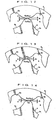
- Fig. 11(A) is a plan view showing the amount of retraction of respective large clearance tips of an inner rotor, Fig. 11(B) is a plan view showing the amount of retraction of respective large clearance tips of an outer rotor and Fig. 11(C) is an enlarged plan view of a maximum clearance formed by the respective large clearance tips of the inner rotor and the outer rotor,
- Fig. 12 is an enlarged plan view of a large clearance formed on a large clearance tip which is greater than the respective tip clearances of the inner rotor and outer rotor,
- Fig. 13 is an enlarged plan view of a large clearance formed by a large clearance tip on the inner rotor alone,
- Fig. 14 is an enlarged plan view of a large clearance formed by a large clearance tip on the outer rotor alone,
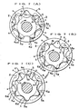
- Fig. 15(A) is a plan view of an inner rotor wherein the large clearance tips are arranged in a uniform fashion, Fig. 15(B) is a plan view of an inner rotor wherein the large clearance tips are arranged in a non-uniform fashion and Fig. 15(C) is a plan view of an inner rotor wherein the large clearance tips are arranged in a non-uniform fashion according to a different pattern,
- Fig. 16 is a plan view showing the shape of a large clearance tip formed by an inner rotor and outer rotor.
-
- Below, embodiments of the present invention are described with reference to the drawings. As shown in Fig. 1, the trochoidal pump according to the present invention comprises an
inner rotor 5 and anouter rotor 6 having a trochoidal toothed shape installed in a rotor chamber 1 formed inside a casing, similarly to a general trochoidal pump. The rotor chamber 1 is formed with anintake port 2 and anoutlet port 3 extending in the circumferential direction in the vicinity of the outer circumference. Theintake port 2 and theoutlet port 3 are formed in laterally symmetrical positions about the centre of the rotor chamber 1. - The
inner rotor 5 has a number of teeth one fewer than theouter rotor 6, and a relationship is formed whereby each time theinner rotor 5 performs one whole revolution, theouter rotor 6 rotates with a delay equivalent to one tooth behind the inner rotor. In this way, theinner rotor 5 comprisestooth crests 5a which project in an outward direction and concave shapedtooth valleys 5b, and similarly, theouter rotor 6 comprisestooth crests 6a which project towards the centre from the inner circumference thereof, and concaveshaped tooth valleys 6b. Theinner rotor 5 andouter rotor 6 always intermesh at one point,tooth crests 5a of theinner rotor 5 being introduced intotooth valleys 6b of theouter rotor 6 andtooth crests 6a of theouter rotor 6 being introduced intotooth valleys 5b of theinner rotor 5. - As shown in Fig. 1, a plurality of demarcated spaces s, s, ··· are formed between the
inner rotor 5 and theouter rotor 6 when they are operated, and by means of the rotatinginner rotor 5 andouter rotor 6, fluid is taken in via theintake port 2 whilst the spaces on theinput port 2 side gradually increase in volume, and furthermore, fluid is expelled from theoutlet port 3 whilst the spaces s on theoutlet port 3 side gradually decrease in volume. - In the trochoidal pump described above, in the shape of the teeth where the
inner rotor 5 andouter rotor 6 intermesh, a clearance which is greater than the normally set tip clearance d0, in other words, a large clearance d1, is set as illustrated in Fig. 1 and Fig. 2. The tooth crests for achieving this large clearance d1 are formed on either theouter rotor 6 or theinner rotor 5. - In setting a large clearance d1 of this kind, as shown in Fig. 4, a
large clearance tip 5a1 is formed on a suitable one or plurality of the crest ends of the plurality oftooth crests 5a of theinner rotor 5. Alternatively, as shown in Fig. 5, alarge clearance tip 6a1 is formed on a suitable one or plurality of the crest ends of the plurality oftooth crests 6a of theouter rotor 6. The tooth shape of thelarge clearance tips - The generally established tip clearance d0 is set uniformly, and by providing a tooth crest set especially to a large clearance d1 in the rotor teeth, the tip clearance d0 of the intermeshing rotors becomes non-uniform. For example, if the tooth crests are set in such a manner that a large clearance d1 is provided in two places on an
inner rotor 5 having four teeth, then the large clearance is provided every other tooth and there will be tooth crests having the normally established tip clearance of d0 between these tooth crests. Moreover, if tooth crests having a large clearance d1 are provided in two places in an inner rotor having six teeth, then they will be provided at intervals of three teeth, or an intervals of two teeth and fourth teeth. - If the
inner rotor 5 has a number of teeth greater than 6, then the tooth crests set to have a large tip clearance d0 are set at least every other tooth position, and hence there will be tooth crests having a large tip clearance d0 set every other tooth position, or at intervals of one teeth and three teeth, as described previously, depending on the number of such teeth set. This applies similarly in cases where theouter rotor 6 has six or more teeth. A tooth crest having a large clearance d1 should be set in at least one position, but desirably a suitable number of such tooth crests are provided, according to the number of teeth on the rotors. Setting a large clearance d1 on a rotor having six teeth or more is desirable, since it allows pulsation to be suppressed without reducing volume efficiency. - Tooth crests having an enlarged clearance d1 make it possible to reduce the number of enclosed space volumes by interconnecting the spatial volumes formed between the intermeshing rotors, thus reducing pulsation, and hence pulsation can be suppressed to a low value. Furthermore, any reduction in volume efficiency caused by interconnection of the spatial volume between the rotors can be restricted by designing the rotors to have six or more teeth. In other words, adjacent spaces s, s are interconnected by means of the large clearance d1, thereby permitting the passage of fluid and preventing enclosure of the fluid.
- Next, if the
inner rotor 5 orouter rotor 6 has an even number of teeth, then of the number of rotor teeth n, a number of tooth crests equal to n/2 are set to have a large clearance d1. The tooth crests formed with a large clearance d1 are set at the least every other tooth. If the number of teeth n is even, then by setting the number of tooth crests formed with a large clearance d1 to n/2, it is possible to a well balanced arrangement, and pulsation can be suppressed whilst maintaining volume efficiency. - Furthermore, if the
inner rotor 5 orouter rotor 6 has an odd number of teeth, then of the number of rotor teeth n, a number of tooth crests (n-1)/2 are set to have a large clearance d1, these being disposed at the least every other tooth, similarly to the foregoing description. In the case of an odd number of teeth, the ratio of the number of tooth crests having a standard tip clearance d0 is set to a larger ratio, and furthermore, the tooth crests formed with a large clearance d1 are not arranged equidistantly. Since the sequence of the tip clearance d0 and the large clearance d1 will be non-regular and non-uniform, and the positioning of the tooth crests having a large clearance d1 will also be non-uniform, the regularity of the hydraulic pulsation will be disturbed, thus disrupting the resonance, and hence pulsation can be suppressed and volume efficiency can be maintained. - Thereby, the tip clearance d0 of the rotors ceases to be uniform, and assumes a non-uniform state. The large clearance d1 moves in accordance with the meshing rotation of the
outer rotor 6 andinner rotor 5, thereby changing phase. If the number of large clearances d1 is more than one, then the positioning thereof may be uniform or non-uniform with respect to the number of rotor teeth, or it may be non-uniform, regardless of the number of rotor teeth. - By selecting the arrangement thereof suitably, the regularity of the hydraulic pulsation of the pump is disturbed, thus making it possible to prevent resonance due to pulsation and to reduce noise. This is now described on the basis of a graph illustrating this effect. Firstly, the value of the hydraulic pulsation plotted on the Y axis is as shown in the graph, the units being decibels (dB). The graph relates to a rotational speed of 2000 rpm. The waveform of the graph is achieved by measuring the frequency of the hydraulic pulsation (the resonance speed).
- The standard value graph shows data for a normal trochoidal type oil pump. The frequency of the hydraulic pulsations in this graph is determined by the rotational speed of the pump and the number of teeth of the rotors. In this graph specifically, the pump speed is 2000 rpm, the number of teeth n of the
inner rotor 5 is 6 and the number of teeth n of theouter rotor 6 is 7, and the graph shows the frequency generated by these rotors. For example, graphs are illustrated for a pump having a standard tip clearance d0 (standard value) (see Fig. 10), a pump wherein the large clearance d1 is set in two places (on two teeth) (see Fig. 8), and a pump wherein the large clearance d1 is set in three places (three teeth) (see Fig. 9), each graph depicting the corresponding state of the hydraulic pulsation. - In these conditions, as shown in Fig. 10, it can be seen that the standard value (STD) graph has a waveform of regular pulsations. The graphs for pumps having a large clearance d1 on two teeth and three teeth each show a significant variation in waveform compared to the standard value. In addition to the non-uniform positioning of the tip clearances d0 and the large clearances d1, it can be seen that the variation in waveforms also differs according to the three toothed arrangement wherein a large clearance d1 is provided every other tooth or the two toothed arrangement wherein it is provided every three teeth.
- Next, it can also be seen that the pumps provided with tooth crests formed with large clearances d1 on two or three teeth achieve a reduction with respect to the oscillation at 324 Hz which is indicated as a frequency where a strong hydraulic pulsation is obtained in the standard value. As shown in Fig. 8 and Fig. 9, in these pumps with two or three teeth having a large clearance, the pulsation is stronger at a lower frequency than 324 Hz. Both the two and three tooth versions have a maximum pulsation at some 175 Hz lower than the standard value. By changing the strongest frequency of the pulsation in the standard value to another, lower, frequency, and increasing the surrounding frequencies, it is possible to suppress the pulsation of particular frequencies which provoke resonance, and at the same time, the oscillation caused by pulsation is prevented from extending into particular frequencies, and hence the sound generated becomes a sound which is not liable to be heard and consequently the noise can be reduced. The tooth crests 5a formed with a large clearance d1 are
tooth crests 5a which have a large clearance d1 compared to the tooth crests 5a having a standard tip clearance d0. To describe this in mechanical terms, the standard tip clearance d0 is the clearance required to achieve a rotational sliding motion whilst respectively sealing the volume spaces created by the intermeshing of theouter rotor 6 andinner rotor 5. On the other hand, the large clearance d1 is set appropriately to value whereby two volume spaces are connected. - The characteristics of the graph in Fig. 10 illustrating the standard value comprising a standard tip clearance d0 only are such that a regular pointed waveform is created. This waveform is shown in first, second and third order sections in the graph. The pointed waveform is such that only the particular frequency projects significantly. The graph shows hydraulic pulsation (oscillation), but if this pulsation causes resonance with the oil filter, and the like, via the piping of the pump, thus appearing as sound, then this sound will be a particular sound having the particular frequency which projects in the graph, and it will be heard continually, thus creating an annoying noise.
- The graph for the two tooth non-uniform composition (see Fig. 8) shows the waveform in a case where the rotational speed is maintained at a uniform 2000 rpm and the tip clearance d0 in two of the six tooth crests of the
inner rotor 5 is increased to a large clearance of d in a rotor of the standard value (STD) described above. - Looking at the two tooth non-uniform graph, the waveform wherein a particular frequency projects in a peaked shape is reduced in comparison with the standard value. In particular, it can be seen that there is no significantly projecting waveform, as in the first, second and third-order sections of the standard value graph, the frequencies surrounding the first, second and third-order frequencies are also increased, and the projecting state of a particular frequency is eased (see corresponding portions of the graphs). Since a sound is generated at a particular frequency in the standard value design, this sound is readily audible and creates a bothersome noise. In the two tooth non-uniform composition, rather than the sound generated at a particular frequency becoming intensified, the surrounding frequencies are also increased, and hence a variety of sounds are combined together, forming a diverse sound which is not readily audible. As a result, the noise is reduced.
- This occurs similarly in the case of the three-tooth non-uniform graph also. A waveform containing somewhat more projecting points than the two tooth non-uniform graph is shown. This is because three of the six tooth crests of the
inner rotor 5 are formed with a large clearance d1 which is greater than the tip clearance d0 and hence these three tooth crests are disposed every other tooth, and the disturbance of the regularity is reduced, but since the waveform of the adjacent frequencies is increased compared to the standard value (STD), these sounds are combined together, thereby forming a diverse sound which is not readily audible and hence noise is reduced. - To describe how a stable rotational state is obtained in the
inner rotor 5 andouter rotor 6, in the driving of the rotors, there are drive intermesh regions in two or three locations from the start end side of theintake port 2 to the finish end side thereof, as shown in Figs. 7(A) and (B). Of the tooth crest contact regions involved in drive intermesh, there are intermeshing regions where the clearance is the standard tip clearance d0, and regions where the respective tooth crests do not make contact due to the large clearance d1. Adjacent spaces, s, s are mutually interconnected via the large clearances d1, thus reducing the number of enclosed spatial volumes and restricting pulsation. Moreover, in the region of the standard tip clearance d0, theinner rotor 5 andouter rotor 6 support each other mutually at contact point t caused by the intermeshing of the respective tooth crests of theinner rotor 5 and theouter rotor 6, and hence play in the radial direction of the rotors can be prevented. Thereby, pulsation becomes less liable to occur and a stable rotational state can be achieved. The mutual support between theinner rotor 5 and theouter rotor 6 due to the standard tip clearance d0 is also performed in the region outside the scope of theintake port 2, as illustrated in Fig.7(C). - Next, there are two arrangement patterns for the plurality of large clearances d1, d1, ···. In a first pattern, the plurality of large clearances d1, d1, ··· are arranged uniformly. For example, as shown in Fig. 15(A), if the number of teeth in the
inner rotor 5 is eight, thenlarge clearance tips 5a1 ontooth crests 5a formed with a large clearance d1 are provided every other tooth. - In a second pattern for arrangement of a plurality of large clearances d1, d1, ···, this plurality of large clearances d1, d1, ··· are arranged in a non-uniform fashion. For example, if the
inner rotor 5 has eight teeth, similarly to the first pattern, then as shown in Fig. 15(B), after a firstlarge clearance tip 5a1 where atooth crest 5a is formed with a large clearance d1, the nextlarge clearance tip 5a1 is formed at a spacing of three teeth. Thereupon, the nextlarge clearance tip 5a1 is formed at a further spacing of two teeth. Moreover, as shown in Fig. 15(C), after a firstlarge clearance tip 5a1 where atooth crest 5a is formed with a large clearance d1, the nextlarge clearance tip 5a1 may be formed at a spacing of two teeth. Thereupon, the nextlarge clearance tip 5a1 is formed at a further spacing of four teeth. - In this way, the
large clearance tips 5a1 where tooth crests 5a are provided with a large clearance d1 are formed appropriately, in such a manner that there is no regularity in the positioning of thelarge clearance tips inner rotor 5 has an odd number of teeth. - The patterns where the aforementioned large clearances d1, d1, ··· are arranged in uniform or non-uniform fashion were described on the basis of the
inner rotor 5, but it is of course possible to base the uniform or non-uniform arrangement pattern of the large clearances d1, d1, ··· on theouter rotor 6, and to set the arrangement of the tooth crests 6a, 6a, ··· formed with large clearances d1, d1, ··· appropriately. A uniform arrangement of this plurality of large clearances d1, d1, ··· is possible in the case of a rotor with six or four teeth, as well as one with eight teeth, but it is conditioned upon the fact that the number of teeth is even. - In the present invention, the large clearance d1 in the position of region (A) in Fig. 16 is taken to be the same large clearance d1 as the large clearances d1 in the positions of regions (B) and (C). In other words, when a space s is formed between the
inner rotor 5 andouter rotor 6, if the minimum space between thetooth crest 5a of theinner rotor 5 and thetooth crest 6a of theouter rotor 6 enclosing the space s is greater than the standard tip clearance d0, then this is taken as a large clearance d1. - Therefore, in the present invention, the large clearance d1 at the position where the respective foremost ends of the
tooth crest 5a of theinner rotor 5 and thetooth crest 6a of theouter rotor 6 are mutually opposing, as in region (A) in Fig. 16, and the large clearance d1 at the position where thefront crest 5a andfront crest 6a are mutually opposing in positions wherein the respective foremost ends thereof are mutually displaced, as in region (B) and region (C) in Fig. 16, are treated as large clearances d1 of the same conditions. In other words, in the arrangement of the large clearances d1, d1, ··· described above, region (A), region (B) and region (C) illustrated in Fig. 16 are mixed together appropriately, and they are distributed in a uniform or non-uniform manner. - Next, in terms of the interval dimensions of the plurality of large clearances d1, d1, ···, there are the following plurality of patterns. Firstly, in a first pattern of interval dimensions, the interval dimensions of all of the large clearances d1, d1, ··· formed are taken to be the same. In other words, the respective large clearances d1,d1, ··· at region (A), region (B) and region (C) in Fig. 16 all have the mutually equal interval dimensions, as described previously. In this case, the fluid interconnected between the spaces s via the large clearance d1 is the same in each of the locations of the large clearances d1, d1, ···. Consequently, the non-regularity of the pulsation during operation of the pump is generated at two different positions, those of the tip clearance d0 and the large clearance d1, thus producing a simple non-regularity.
- Next, in a second pattern for interval dimensions, the interval dimensions of all of the large clearances d11, d12, ··· formed are mutually different, and there exist no large clearances d1, d1, ··· which have the same interval dimensions. Here, the addition of suffixes to the large clearances d11, d12, ··· makes it easier to distinguish between the respective large clearances d1, d1, ···, in cases where the interval dimensions thereof are mutually different, as described above. In other words, in this case, the amount of fluid connected between spaces s via the large clearance d1 is different in each of the respective large clearances d11, d12, ···. Therefore, the non-regularity of the pulsation during pump operation is generated not only by the tip clearance d0 and the large clearance d1, but also by the plurality of different large clearances d11, d12, ···. In this second pattern of interval dimensions, the non-regularity of the pulsation is enhanced.
- Next, in a third pattern of interval dimensions, the interval dimension of at least one large clearance d1' of the plurality of large clearances d1, d1, ··· formed is different from the interval dimensions of the other large clearances d1, d1, ···. For example, if there are four large clearances d1, d1, ··· in a rotor set comprising an
inner rotor 5 andouter rotor 6, then one of these large clearances d1' is set to a different interval dimension from the other three large clearances d1, d1, ···. In this third pattern of interval dimensions, the non-regularity of pulsation is approximately midway between that of the first pattern and the second pattern. The (') symbol in the large clearance d1' described above is used to distinguish it readily from the other large clearances d1, d1, ···. - Next, with regard to the formation of the large clearances d1, d1, ···, as described previously, large clearances d1 are created by forming
large clearance tips 5a1 on tooth crests 5a of theinner rotor 5, or by forminglarge clearance tips 6a1 on the tooth crests 6a of the outer rotor. There are a plurality of patterns for forming the large clearances d1 and in a first formation pattern, the large clearances d1 are formed only onlarge clearance tips 5a1 on the inner rotor 5 (see Fig. 13), or they are formed only onlarge clearance tips 6a1 on the outer rotor 6 (see Fig. 14). In this first formation pattern, the large clearances d1, d1, ··· are formed in such a manner that all have the same interval dimensions, as described in the interval dimension patterns for the large clearances d1 mentioned above. - In other words, if the large clearances d1 are formed only on
large clearance tips 5a1 on theinner rotor 5, then the tooth crests are retracted by an even amount and the plurality oflarge clearance tips large clearance tips - Furthermore, in the second formation pattern, the tooth crests 5a are retracted by mutually different amounts, thereby causing the size of a plurality of
large clearance tips large clearance tips large clearance tips - Moreover, in the third formation pattern, by setting a suitable one
large clearance tip 5a1' of a plurality oflarge clearance tips large clearance tips - In the description of the second and third formation patterns explained above, the large clearances d11, d12, ... were constituted by forming a plurality of
large clearance tips inner rotor 5, but it is also possible to set a plurality oflarge clearance tips outer rotor 6 to mutually different sizes, or to set a suitable onelarge clearance tip 6a1 of a plurality oflarge clearance tips outer rotor 6 to a different size from the otherlarge clearance tips large clearance tips large clearance tips - Moreover, in a fourth formation pattern for the large clearances d1, d1, ···, as shown in Figs. 11(A) and (B),
large clearance tips 5a1 are formed on tooth crests 5a of theinner rotor 5, and furthermore,large clearance tips 6a1 are formed on the tooth crests 6a of theouter rotor 6. When alarge clearance tip 5a1 on theinner rotor 5 is opposing atooth crest 6a on theouter rotor 6, or when alarge clearance tip 6a1 of theouter rotor 6 is opposed atooth crest 5a of theinner rotor 5, then the aforementioned large clearance d1 is created, and moreover, when alarge clearance tip 5a1 of theinner rotor 5 is opposing alarge clearance tip 6a1 of theouter rotor 6, then a maximum clearance dmax, which is larger than the large clearance d1, is created. - As shown in Fig. 11(C), this maximum clearance dmax is the sum of the greatest amount of retraction q of the
large clearance tip 5a1 and the greatest amount of retraction q' of thelarge clearance tip 6a1, and in terms of an equation, dmax = q + q'. - The maximum clearance dmax has an interval dimension which is greater than the standard large clearance d1, in other words, the large clearance d1 created by the retraction of the circumferential edge of one only of either a
tooth crest 5a of theinner rotor 5 or atooth crest 6a of theouter rotor 6. - Next, in a fifth formation pattern for the large clearances d1, d1, ···, as shown in Fig. 12, the large clearance d1 may be formed by means of a
large clearance tip 5a1 on theinner rotor 5 and alarge clearance tip 6a1 on theouter rotor 6. - In the fourth pattern and fifth formation patterns described above, by setting the respective amounts of retraction q, q, ··· of the
large clearance tips inner rotor 5 to the same or mutually different amounts, and by setting the respective amounts of retraction q', q', ··· of thelarge clearance tips outer rotor 6 to the same or mutually different amounts, then it is possible to set the plurality of large clearances d11, d12, ··· formed by theselarge clearance tips - For example, if the respective amounts of retraction q1, q2, q3 of the respective
large clearance tips inner rotor 5 are considered, then the following mutual relationships exist between these respective amounts of retraction.
(1) q1 = q2 = q3, (2) q1 ≠ q2 ≠ q3, (3) q1 = q2 ≠ q3,
(4) q1 ≠ q2 = q3, (5) q1 = q3 ≠ q2, - Moreover, the relative magnitudes of the retraction amounts q1, q2, q3 are as follows.
(6) q1 > q2, (7) q1 < q2, (8) q2 > q3, (9) q2 < q3,
(10) q1 > q3, (11) q1 < q3. - Similarly, if the respective amounts of retraction q1', q2', q3' of the respective
large clearance tips outer rotor 6 are considered, then the following mutual relationships exist between these respective amounts of retraction.
(1) q1' = q2' = q3', (2) q1' ≠ q2' ≠ q3', (3) q1' = q2' ≠ q3',
(4) q1' ≠ q2' = q3', (5) q1' = q3' ≠ q2', - Moreover, the relative magnitudes of the retraction amounts q1, q2, q3 are as follows.
(6) q1' > q2', (7) q1' < q2', (8) q2' > q3', (9) q2' < q3',
(10) q1' > q3', (11) q1' < q3'. - In a composition wherein a maximum clearance dmax according to the fourth pattern and large clearances d1 according to the fifth pattern are formed by means of
large clearance tips 5a1 on theinner rotor 5 andlarge clearance tips 6a1 on theouter rotor 6, then if the conditions of the amounts of retraction of thelarge clearance tips 5a1 on theinner rotor 5 are q1 = q2 = q3, and the amounts of retraction of thelarge clearance tips 6a1 on theouter rotor 6 are q1' = q2' = q3', the maximum clearance dmax and the large clearances d1 created by theinner rotor 5 and theouter rotor 6 will be uniform values. - Moreover, if the conditions of the amounts of retraction of the
inner rotor 5 are taken to be q1 ≠ q2 ≠ q3, and the amounts of retraction of theouter rotor 6 are taken to be q1' ≠ q2' ≠ q3', then there will exist various combinations of values for the maximum clearance dmax in the fourth pattern and the large clearance d1 in the fifth pattern, as created by theinner rotor 5 andouter rotor 6. - The maximum clearance dmax in the fourth pattern will be of a varying size, whilst the large clearance d1 in the fifth pattern will be of uniform size.
- In other words, in the case of the maximum clearance dmax, in the fourth pattern, since the maximum clearance dmax and the retraction amounts forming it are different on the
inner rotor 5 and theouter rotor 6, large clearances d1 of a variety of sizes are formed when opposing atooth crest 5a on the inner rotor or atooth crest 6a on theouter rotor 6. - Moreover, in the case of the large clearance d1 in the fifth pattern, although the large clearances d1 created by the combination of rotors will be of uniform size, since the amounts of retraction forming these clearances are different on the
inner rotor 5 and theouter rotor 6, the large clearance d1 greater than the tip clearance d0, which is formed when opposing thetooth crest 5a of theinner rotor 5 or thetooth crest 6a of theouter rotor 6, will be of varying size. The combinations of maximum clearance dmax in the fourth pattern and the respective amounts of retraction in the large clearance d1 in the fifth pattern are as described below.
(1) q1 + q1', (2) q1 + q2', (3) q1 + q3',
(4) q2 + q1', (5) q2 + q2', (6) q2 + q3',
(7) q3 + q1', (8) q3 + q2', (9) q3 + q3'. - The plurality of large clearances d1, d1, ··· or the maximum clearance dmax are constituted by the aforementioned combinations, and the interval dimensions of the respective large clearances d1, d1, ··· based on the respective amounts of retraction described above are respectively different, which means that when the pump operates, since the large clearances d1, d1, ··· each have mutually different interval dimensions, it is possible to generate non-regularity in the pulsing action.
- The invention according to a first claim concerns a trochoidal pump wherein an
inner rotor 5 and anouter rotor 6 having trochoidal toothed shapes are provided in a mutually intermeshing state, in such a manner that a tip clearance d0 is created between eachtooth crest 5a of theinner rotor 5 and theouter rotor 6, a large clearance d1 forming a large interval being provided in at least one location of the group of the tip clearances d0, whereby pulsation can be suppressed whilst maintaining volume efficiency. - In other words, there are tip clearances d0, d0, ··· between the
inner rotor 5 and theouter rotor 6, at least one of this group of tip clearances d0 being set to a large clearance d1 forming a large interval, and by including a large clearance d1 in the group of tip clearances d0, the regular pulsation generated by a group of tip clearances d0 only, which in turn causes resonance in the trochoidal pump itself and in the peripheral devices, becomes a pulsation of a non-regular cycle, and hence the aforementioned resonance is prevented and noise can be suppressed to a low level. By consequence, it is also possible greatly to improve the lifespan of both the trochoidal pump and the peripheral devices supplied with fluid by the trochoidal pump. - Moreover, since a large clearance d1 is simply included in the group of tip clearances d0 between the
inner rotor 5 andouter rotor 6, this composition can be adopted readily. This can be achieved by forming a tooth crest of either theinner rotor 5 or theouter rotor 6 to a slightly lower shape, and hence the aforementioned merits can be obtained by means of an extremely simple composition. - The invention according to a second claim concerns the trochoidal pump of the first claim, wherein the number of teeth of the
inner rotor 5 is six or more, and a large clearance d1 is formed between theinner rotor 5 and theouter rotor 6, on the plurality of tooth crests 5a of theinner rotor 5, at least at every other tooth position, whereby, if the inner rotor 5 (or outer rotor 6) has six or more teeth, the positions at which the clearance created between atooth crest 5 of the inner rotor and theouter rotor 6 becomes a large clearance d1 are set to be at least every other tooth position of theinner rotor 5, and by selecting the number and arrangement thereof appropriately, a variety of pump performances can be provided readily. Moreover, if the maximum setting number of three tip clearances d0 and three large clearances d1 provided on alternate teeth is adopted, then although the large clearances d1, d1, ··· form a tooth shape which does not perform rotational drive of the rotors, since they form an interconnected state during intermeshing of the rotors, they allow a well balanced arrangement of the tip clearances d0 which maintain rotational drive intermeshing of the rotors, and hence the rotation of the rotors can be stabilized. - In other words, there are drive intermesh sections in two to three positions between the start end side and the finish end side of the
intake port 2, and of the tooth crest contact regions involved in drive intermesh, there are intermeshing regions where the clearance is the standard tip clearance d0, and regions where the respective tooth crests d0 not make mutual contact due to the large clearance d1, the adjacent spaces, s, s being mutually interconnected via the large clearances d1, thus reducing the number of enclosed spatial volumes and restricting pulsation. Moreover, in the region of the standard tip clearance d0, theinner rotor 5 andouter rotor 6 support each other mutually due to intermeshing between the respective tooth crests of theinner rotor 5 and theouter rotor 6, and hence play in the radial direction of the rotors can be prevented, thereby making pulsation becomes less liable to occur and making it possible to achieve a stable rotational state. - The invention according to the third claim concerns the trochoidal pump according to
claims 1 or 2, wherein, taking the number of teeth of theinner rotor 5 orouter rotor 6 as n, large clearances d2, d1, ··· are arranged in a uniform or non-uniform fashion on appropriate tooth crests 5a, 6a of the teeth, whereby the large clearances d1, d1, ··· are arranged in a uniform or non-uniform fashion, and together with the standard tip clearances d0, they are able to generate non-regularity in the pulsation caused by the operation of the pump, thus increasing the degree to which resonance can be prevented and noise can be reduced to a low level. - The invention according to the fourth claim concerns the trochoidal pump according to
claim inner rotor 5 is set to an even number, and a large clearance d1 is provided every other tooth on (n/2) tooth crests, whereby, if the number of teeth, n, of the inner rotor (or the outer rotor 6) is an even number, then the tooth crests forming a large clearance d1 can be set to be at least in every other tooth position. Therefore, if the number of teeth n is even, the regions formed with a large clearance d1 can be set to n/2 regions, and a well-balanced arrangement between the tip clearance d0 and the large clearance d1 can be achieved, thus making it possible to suppress pulsation whilst maintaining volume efficiency. - The invention according to the fifth claim concerns the trochoidal pump according to
claim inner rotor 5 is set to an odd number, and a large clearance d1 is provided at least every other tooth position or every other two tooth positions, on ((n-1)/2) tooth crests, whereby the sequence of the positions of the tip clearances d0 and large clearances d1 becomes non-uniform, rather than being systematic, in addition to which the positioning of the tooth crests having large clearance d1 becomes non-uniform, thereby disturbing the regularity of the hydraulic pulsations, avoiding resonance, and hence making it possible suppress pulsation whilst ensuring volume efficiency. - The invention according to the sixth claim concerns the trochoidal
pump according claim inner rotor 5 orouter rotor 6 for forming the large clearances d1, d1, ··· can be achieved in a comparatively easy fashion. - The invention according to the seventh claim concerns the trochoidal pump according to
claim - The invention according to the eighth claim concerns the trochoidal pump according to
claim - The invention according to the ninth claim concerns the trochoidal pump according to
claim inner rotor 5 or tooth crests 6a of theouter rotor 6, whereby the structure can be achieved in an extremely easy fashion, since the circumferential edges of tooth crests of either theinner rotor 5 orouter rotor 6 are retracted. - The invention according to the tenth claim concerns the trochoidal pump according to
claim inner rotor 5 and tooth crests 6a of theouter rotor 6, whereby there will exist large clearances d1 of the plurality of large clearances d1, d1, ···, which are formed by alarge clearance tip 5a1 of theinner rotor 5 and alarge clearance tip 6a1 of theouter rotor 6. - If a
large clearance tip 5a1 andlarge clearance tip 6a1 become mutually opposing due to rotation of the rotors, then a particularly big large clearance d1 (in other words, a maximum clearance dmax) will occur amongst the large clearances d1, d1, ···, and by retracting the tooth crests 5a of theinner rotor 5 and the tooth crests 6a of the outer rotor appropriately, it is possible to provide large clearances d1 of a variety of sizes, whereby the non-regularity of the pulsation caused by pump operation becomes even more pronounced, thus increasing the degree to which the resonance can be prevented and noise can be reduced to a low level. In the foregoing case, dmax = q + q'. - Moreover, when a
large clearance tip 5a1 and alarge clearance tip 6a1 oppose each other due to rotation of the rotors, large clearances d1, d1, ··· are formed, and when atooth crest 5a of theinner rotor 5 or atooth crest 6a of theouter rotor 6 opposes such alarge clearance tip 5a1 orlarge clearance tip 6a1, then a large clearance d1 which is greater than the tip clearance d0 but smaller than the aforementioned large clearance d1 (equal to the maximum clearance dmax) is formed, whereby the large clearance d1 can be set to a variety of sizes by means of retracting the tooth crests 5a of theinner rotor 5 and the tooth crests 6a of theouter rotor 6 by appropriate amounts, thus enhancing the non-regularity of the pulsation during pump operations, and increasing the degree to which resonance can be prevented and noise reduced to a low level. In the foregoing, d1 = q + q'.
Claims (10)
- A trochoidal pump comprising an inner rotor (5) and an outer rotor (6) having trochoidal toothed shapes (5a, 6a) provided in a mutually intermeshing state, in such a manner that a normal tip clearance (d0) is created between a first number of tooth crests of the inner rotor (5) and the outer rotor (6), characterised in that one or more second tooth crests of one or both of the inner and outer rotors is formed with a tip displaced radially with respect to the first tooth crests of the corresponding rotor so as to define a larger clearance (d1) than the normal tip clearance (d0).
- The trochoidal pump according to claim 1, characterized in that the number of teeth of said inner rotor (5) is six or more, and the larger clearance is formed between said inner rotor (5) and said outer rotor (6), on the plurality of tooth crests of said inner rotor (5), at least at every other tooth position.
- The trochoidal pump according to claim 1 or claim 2, characterized in that, taking the number of teeth of said inner rotor (5) or outer rotor (6) as n, larger clearances d1 are arranged in a uniform or non-uniform fashion on appropriate tooth crests 5a, 6a of said teeth.
- The trochoidal pump according to claim 1, 2 or 3, characterized in that the number of teeth, n, of said inner rotor (5) is set to an even number, and the larger clearance is provided every other tooth on (n/2) tooth crests.
- The trochoidal pump according to claim 1, 2 or 3, characterized in that the number of teeth, n, of said inner rotor (5) is set to an odd number, and the larger clearance d1 is provided at least every other tooth position or every other two tooth positions, on ((n-1)/2) tooth crests.
- The trochoidal pump according claim 1, 2, 3, 4 or 5, characterized in that there are a plurality of said larger clearances d1, and all of these larger clearances d1 have the same interval dimension.
- The trochoidal pump according to claim 1, 2, 3, 4 or 5, characterized in that there are a plurality of said larger clearances d1, and all of these large clearances d1 have mutually different interval dimensions.
- The trochoidal pump according to claim 1, 2, 3, 4, or 5, characterized in that there are a plurality of said larger clearances d1, and at least one of all of these larger clearances d1 has a different interval dimension to the other larger clearances d1.
- The trochoidal pump according to claim 1, 2, 3, 4, 5, 6, 7 or 8, characterized in that said larger clearances d1 are formed by retracting the circumferential edges of either tooth crests (5a) of said inner rotor (5) or tooth crests (6a) of the outer rotor (6).
- The trochoidal pump according to claim 1, 2, 3, 4, 5, 6, 7 or 8, characterized in that said larger clearances d1 are formed by retracting the circumferential edges of both tooth crests (5a) of said inner rotor (5) and tooth crests (6a) of the outer rotor (6).
Applications Claiming Priority (4)
| Application Number | Priority Date | Filing Date | Title |
|---|---|---|---|
| JP2002203264 | 2002-07-11 | ||
| JP2002203264 | 2002-07-11 | ||
| JP2003174279A JP2004092637A (en) | 2002-07-11 | 2003-06-19 | Trochoid pump |
| JP2003174279 | 2003-06-19 |
Publications (3)
| Publication Number | Publication Date |
|---|---|
| EP1380754A2 EP1380754A2 (en) | 2004-01-14 |
| EP1380754A3 EP1380754A3 (en) | 2004-03-31 |
| EP1380754B1 true EP1380754B1 (en) | 2005-11-02 |
Family
ID=29738481
Family Applications (1)
| Application Number | Title | Priority Date | Filing Date |
|---|---|---|---|
| EP03254305A Expired - Lifetime EP1380754B1 (en) | 2002-07-11 | 2003-07-07 | Trochoidal pump |
Country Status (6)
| Country | Link |
|---|---|
| US (1) | US7052258B2 (en) |
| EP (1) | EP1380754B1 (en) |
| JP (1) | JP2004092637A (en) |
| CN (1) | CN100430601C (en) |
| DE (1) | DE60302110T2 (en) |
| ES (1) | ES2252624T3 (en) |
Families Citing this family (15)
| Publication number | Priority date | Publication date | Assignee | Title |
|---|---|---|---|---|
| JP2006107601A (en) * | 2004-10-04 | 2006-04-20 | Pioneer Electronic Corp | Disk device |
| JP4319617B2 (en) | 2004-12-27 | 2009-08-26 | 株式会社山田製作所 | Trochoid oil pump |
| JP4584770B2 (en) * | 2005-05-20 | 2010-11-24 | ペガサスミシン製造株式会社 | Sewing machine oiling equipment |
| JP5158448B2 (en) * | 2007-03-09 | 2013-03-06 | アイシン精機株式会社 | Oil pump rotor |
| JP4796035B2 (en) * | 2007-10-21 | 2011-10-19 | 株式会社山田製作所 | Method for producing trochoidal pump and trochoidal pump |
| JP4967180B2 (en) * | 2009-09-04 | 2012-07-04 | 住友電工焼結合金株式会社 | Internal gear pump |
| JP5479934B2 (en) * | 2010-02-05 | 2014-04-23 | アイシン・エィ・ダブリュ株式会社 | Oil pump |
| CN102939436B (en) * | 2010-05-05 | 2016-03-23 | 能量转子股份有限公司 | Fluid energy converting device |
| JP5795726B2 (en) * | 2011-06-27 | 2015-10-14 | 株式会社山田製作所 | Oil pump |
| US8714951B2 (en) * | 2011-08-05 | 2014-05-06 | Ener-G-Rotors, Inc. | Fluid energy transfer device |
| DE102011089609A1 (en) * | 2011-12-22 | 2013-06-27 | Robert Bosch Gmbh | Internal gear pump |
| JP5982935B2 (en) * | 2012-03-27 | 2016-08-31 | トヨタ自動車株式会社 | Control device for internal combustion engine |
| CN104454521A (en) * | 2014-12-05 | 2015-03-25 | 西安航空动力控制科技有限公司 | Cycloid outer rotor of internally-engaged cycloid pump |
| DE102015004984A1 (en) | 2015-04-18 | 2016-10-20 | Man Truck & Bus Ag | Internal gear pump and vehicle with an internal gear pump |
| US10895257B2 (en) * | 2018-02-13 | 2021-01-19 | GM Global Technology Operations LLC | Lubrication strategy for dry run pump system |
Family Cites Families (12)
| Publication number | Priority date | Publication date | Assignee | Title |
|---|---|---|---|---|
| JPS55148991A (en) * | 1979-05-09 | 1980-11-19 | Sumitomo Electric Ind Ltd | Method of correcting rotor curve of rotary pump utilizing trochoidal curve |
| JPS5920591A (en) * | 1982-07-23 | 1984-02-02 | Sumitomo Electric Ind Ltd | Sintered rotor for rotary pump and method of manufacturing thereof |
| JPS59173584A (en) * | 1983-03-23 | 1984-10-01 | Sumitomo Electric Ind Ltd | Rotary pump and its rotor for oil pump lubricating internal-combustion engine |
| JPS61210282A (en) * | 1985-03-13 | 1986-09-18 | Yamada Seisakusho:Kk | Rotor curve correcting method for internal gear pump in trochoidal engagement |
| JPS6456589A (en) | 1987-08-28 | 1989-03-03 | Mitsubishi Rayon Co | Optical recording material |
| JPH01249971A (en) * | 1988-03-31 | 1989-10-05 | Suzuki Motor Co Ltd | Trochoid pump |
| US5030072A (en) * | 1988-06-20 | 1991-07-09 | Eaton Corporation | Constant radial clearance gerotor design |
| JP2805769B2 (en) * | 1988-09-30 | 1998-09-30 | スズキ株式会社 | Oil pump |
| JPH0295787A (en) | 1988-09-30 | 1990-04-06 | Suzuki Motor Co Ltd | Oil pump |
| JPH02163485A (en) * | 1988-12-16 | 1990-06-22 | Mitsubishi Metal Corp | Inscribed trochoid rotor |
| DE4200883C1 (en) * | 1992-01-15 | 1993-04-15 | Siegfried A. Dipl.-Ing. 7960 Aulendorf De Eisenmann | |
| US5554020A (en) * | 1994-10-07 | 1996-09-10 | Ford Motor Company | Solid lubricant coating for fluid pump or compressor |
-
2003
- 2003-06-19 JP JP2003174279A patent/JP2004092637A/en active Pending
- 2003-07-07 DE DE60302110T patent/DE60302110T2/en not_active Expired - Lifetime
- 2003-07-07 EP EP03254305A patent/EP1380754B1/en not_active Expired - Lifetime
- 2003-07-07 ES ES03254305T patent/ES2252624T3/en not_active Expired - Lifetime
- 2003-07-10 US US10/616,509 patent/US7052258B2/en not_active Expired - Lifetime
- 2003-07-11 CN CNB031545041A patent/CN100430601C/en not_active Expired - Lifetime
Also Published As
| Publication number | Publication date |
|---|---|
| DE60302110D1 (en) | 2005-12-08 |
| US20040057860A1 (en) | 2004-03-25 |
| HK1061880A1 (en) | 2004-10-08 |
| US7052258B2 (en) | 2006-05-30 |
| EP1380754A3 (en) | 2004-03-31 |
| ES2252624T3 (en) | 2006-05-16 |
| JP2004092637A (en) | 2004-03-25 |
| DE60302110T2 (en) | 2006-06-08 |
| EP1380754A2 (en) | 2004-01-14 |
| CN1482361A (en) | 2004-03-17 |
| CN100430601C (en) | 2008-11-05 |
Similar Documents
| Publication | Publication Date | Title |
|---|---|---|
| US7052258B2 (en) | Trochoidal pump | |
| US4673342A (en) | Rotary pump device having an inner rotor with an epitrochoidal envelope tooth profile | |
| JP4557514B2 (en) | Internal gear pump and inner rotor of the pump | |
| JPH0310040B2 (en) | ||
| US7766634B2 (en) | Crescent gear pump with novel rotor set | |
| JP2010196582A (en) | Single screw compressor | |
| JP2006183569A (en) | Trochoid type oil pump | |
| GB2351324A (en) | Regenerative pump impeller | |
| JP4169724B2 (en) | Trochoid oil pump | |
| JP4309952B2 (en) | Trochoid oil pump | |
| JPS61138893A (en) | Trochoidal oil pump | |
| JP4028774B2 (en) | Trochoid pump | |
| JP3127973B2 (en) | Operation Noise Reduction Structure of Internal Gear Type Liquid Pump Using Trochoidal Tooth | |
| JP6080300B2 (en) | Manufacturing method of gear pump and inner rotor | |
| JP2003227474A (en) | Internal gear pump | |
| JP6080635B2 (en) | Manufacturing method of gear pump and inner rotor | |
| Tran et al. | Study on the effects of tooth profile design parameters of rotor to performance of vacuum pump | |
| JPH0419375A (en) | Internal oil motor and internal oil pump | |
| JP2007502932A (en) | Reduced exhaust pump pulsation | |
| JP3644796B2 (en) | Positive displacement pump | |
| HK1061880B (en) | Trochoidal pump | |
| JP3860125B2 (en) | Oil pump rotor | |
| JPH0718416B2 (en) | Rotor for rotary pump | |
| JP6669554B2 (en) | Oil pump | |
| JPH08128392A (en) | Inscribed oil pump rotor |
Legal Events
| Date | Code | Title | Description |
|---|---|---|---|
| PUAI | Public reference made under article 153(3) epc to a published international application that has entered the european phase |
Free format text: ORIGINAL CODE: 0009012 |
|
| AK | Designated contracting states |
Kind code of ref document: A2 Designated state(s): AT BE BG CH CY CZ DE DK EE ES FI FR GB GR HU IE IT LI LU MC NL PT RO SE SI SK TR |
|
| AX | Request for extension of the european patent |
Extension state: AL LT LV MK |
|
| PUAL | Search report despatched |
Free format text: ORIGINAL CODE: 0009013 |
|
| AK | Designated contracting states |
Kind code of ref document: A3 Designated state(s): AT BE BG CH CY CZ DE DK EE ES FI FR GB GR HU IE IT LI LU MC NL PT RO SE SI SK TR |
|
| AX | Request for extension of the european patent |
Extension state: AL LT LV MK |
|
| RIC1 | Information provided on ipc code assigned before grant |
Ipc: 7F 04C 2/10 A |
|
| 17P | Request for examination filed |
Effective date: 20040917 |
|
| 17Q | First examination report despatched |
Effective date: 20041102 |
|
| AKX | Designation fees paid |
Designated state(s): DE ES FR GB IT |
|
| GRAP | Despatch of communication of intention to grant a patent |
Free format text: ORIGINAL CODE: EPIDOSNIGR1 |
|
| GRAS | Grant fee paid |
Free format text: ORIGINAL CODE: EPIDOSNIGR3 |
|
| GRAA | (expected) grant |
Free format text: ORIGINAL CODE: 0009210 |
|
| AK | Designated contracting states |
Kind code of ref document: B1 Designated state(s): DE ES FR GB IT |
|
| REG | Reference to a national code |
Ref country code: GB Ref legal event code: FG4D |
|
| REF | Corresponds to: |
Ref document number: 60302110 Country of ref document: DE Date of ref document: 20051208 Kind code of ref document: P |
|
| REG | Reference to a national code |
Ref country code: DE Ref legal event code: R096 Ref document number: 60302110 Country of ref document: DE Effective date: 20051208 |
|
| REG | Reference to a national code |
Ref country code: ES Ref legal event code: FG2A Ref document number: 2252624 Country of ref document: ES Kind code of ref document: T3 |
|
| ET | Fr: translation filed | ||
| PLBE | No opposition filed within time limit |
Free format text: ORIGINAL CODE: 0009261 |
|
| STAA | Information on the status of an ep patent application or granted ep patent |
Free format text: STATUS: NO OPPOSITION FILED WITHIN TIME LIMIT |
|
| 26N | No opposition filed |
Effective date: 20060803 |
|
| REG | Reference to a national code |
Ref country code: DE Ref legal event code: R097 Ref document number: 60302110 Country of ref document: DE Effective date: 20060802 |
|
| PGFP | Annual fee paid to national office [announced via postgrant information from national office to epo] |
Ref country code: ES Payment date: 20110817 Year of fee payment: 9 |
|
| PGFP | Annual fee paid to national office [announced via postgrant information from national office to epo] |
Ref country code: IT Payment date: 20120713 Year of fee payment: 10 |
|
| REG | Reference to a national code |
Ref country code: ES Ref legal event code: FD2A Effective date: 20131022 |
|
| PG25 | Lapsed in a contracting state [announced via postgrant information from national office to epo] |
Ref country code: ES Free format text: LAPSE BECAUSE OF NON-PAYMENT OF DUE FEES Effective date: 20120708 Ref country code: IT Free format text: LAPSE BECAUSE OF NON-PAYMENT OF DUE FEES Effective date: 20130707 |
|
| PGFP | Annual fee paid to national office [announced via postgrant information from national office to epo] |
Ref country code: FR Payment date: 20140708 Year of fee payment: 12 Ref country code: GB Payment date: 20140702 Year of fee payment: 12 |
|
| GBPC | Gb: european patent ceased through non-payment of renewal fee |
Effective date: 20150707 |
|
| PG25 | Lapsed in a contracting state [announced via postgrant information from national office to epo] |
Ref country code: GB Free format text: LAPSE BECAUSE OF NON-PAYMENT OF DUE FEES Effective date: 20150707 |
|
| REG | Reference to a national code |
Ref country code: FR Ref legal event code: ST Effective date: 20160331 |
|
| PG25 | Lapsed in a contracting state [announced via postgrant information from national office to epo] |
Ref country code: FR Free format text: LAPSE BECAUSE OF NON-PAYMENT OF DUE FEES Effective date: 20150731 |
|
| PGFP | Annual fee paid to national office [announced via postgrant information from national office to epo] |
Ref country code: DE Payment date: 20220531 Year of fee payment: 20 |
|
| REG | Reference to a national code |
Ref country code: DE Ref legal event code: R071 Ref document number: 60302110 Country of ref document: DE |