EP1380507B1 - Binding machine - Google Patents
Binding machine Download PDFInfo
- Publication number
- EP1380507B1 EP1380507B1 EP02705076A EP02705076A EP1380507B1 EP 1380507 B1 EP1380507 B1 EP 1380507B1 EP 02705076 A EP02705076 A EP 02705076A EP 02705076 A EP02705076 A EP 02705076A EP 1380507 B1 EP1380507 B1 EP 1380507B1
- Authority
- EP
- European Patent Office
- Prior art keywords
- tie
- opening
- rear side
- guide
- item
- Prior art date
- Legal status (The legal status is an assumption and is not a legal conclusion. Google has not performed a legal analysis and makes no representation as to the accuracy of the status listed.)
- Expired - Lifetime
Links
- 230000035807 sensation Effects 0.000 abstract description 5
- 238000010276 construction Methods 0.000 description 31
- 230000002093 peripheral effect Effects 0.000 description 5
- 244000145845 chattering Species 0.000 description 2
- 238000006073 displacement reaction Methods 0.000 description 2
- 230000003449 preventive effect Effects 0.000 description 2
- 238000005452 bending Methods 0.000 description 1
- 230000008030 elimination Effects 0.000 description 1
- 238000003379 elimination reaction Methods 0.000 description 1
- 230000035939 shock Effects 0.000 description 1
- 238000009751 slip forming Methods 0.000 description 1
- 125000006850 spacer group Chemical group 0.000 description 1
Images











Classifications
-
- B—PERFORMING OPERATIONS; TRANSPORTING
- B65—CONVEYING; PACKING; STORING; HANDLING THIN OR FILAMENTARY MATERIAL
- B65B—MACHINES, APPARATUS OR DEVICES FOR, OR METHODS OF, PACKAGING ARTICLES OR MATERIALS; UNPACKING
- B65B13/00—Bundling articles
- B65B13/18—Details of, or auxiliary devices used in, bundling machines or bundling tools
-
- B—PERFORMING OPERATIONS; TRANSPORTING
- B65—CONVEYING; PACKING; STORING; HANDLING THIN OR FILAMENTARY MATERIAL
- B65B—MACHINES, APPARATUS OR DEVICES FOR, OR METHODS OF, PACKAGING ARTICLES OR MATERIALS; UNPACKING
- B65B51/00—Devices for, or methods of, sealing or securing package folds or closures; Devices for gathering or twisting wrappers, or necks of bags
- B65B51/04—Applying separate sealing or securing members, e.g. clips
- B65B51/08—Applying binding material, e.g. to twisted bag necks
-
- B—PERFORMING OPERATIONS; TRANSPORTING
- B65—CONVEYING; PACKING; STORING; HANDLING THIN OR FILAMENTARY MATERIAL
- B65B—MACHINES, APPARATUS OR DEVICES FOR, OR METHODS OF, PACKAGING ARTICLES OR MATERIALS; UNPACKING
- B65B13/00—Bundling articles
- B65B13/02—Applying and securing binding material around articles or groups of articles, e.g. using strings, wires, strips, bands or tapes
- B65B13/16—Applying and securing binding material around articles or groups of articles, e.g. using strings, wires, strips, bands or tapes with means for severing the binding material from supply and then applying it around the articles
-
- B—PERFORMING OPERATIONS; TRANSPORTING
- B65—CONVEYING; PACKING; STORING; HANDLING THIN OR FILAMENTARY MATERIAL
- B65B—MACHINES, APPARATUS OR DEVICES FOR, OR METHODS OF, PACKAGING ARTICLES OR MATERIALS; UNPACKING
- B65B13/00—Bundling articles
- B65B13/18—Details of, or auxiliary devices used in, bundling machines or bundling tools
- B65B13/24—Securing ends of binding material
- B65B13/28—Securing ends of binding material by twisting
Definitions
- the present invention relates to a binding machine, and in particular, to a binding machine that ties an item to be tied (referred to as item, hereinafter) such as rod-like item using a tie-like member capable of tying by being twisted.
- the binding machine is provided with an opening available for inserting an item therein.
- a bifurcated arm is moved toward the recess of the opening so as to traverse the opening.
- Both ends of a tie-like member are guided toward the lower portion of the item by the front-end portions of the bifurcated arm; thereby the tie-like member is turned around the item.
- the both ends of the tie-like member are tied by being twisted.
- the conventional binding machine suffers from the problem in which when an operator carries out tying operation by inserting an item into the opening, since the bifurcated arm moves traversing the opening, the operator is given with sensation of fear.
- an object of the present invention is to provide a binding machine with which an operator can carries out the tying operation with security.
- the invention of claim 1 resides in the construction that comprises: a base member having a bifurcated shape in the front side thereof, into which an item can be inserted; a tie feed mechanism that feeds out a tie-like member of a predetermined length in the width direction of the base member so as to transverse an opening formed between the bifurcations of the base member; a tie guide mechanism having a pair of tie guide members capable of moving respectively in the substantially front/rear direction of the base member at the side areas of the opening thereby to press the front end side and the fed-out end side of the tie-like member toward the rear side of the opening by the respective front end portions, and a guide mechanism that guides each tie guide member toward the rear side substantially parallel to the opening, and turns the respective front end portions around toward the rear side of the opening thereby to make the respective front end portions closer to each other at the rear side of the opening; and a tying mechanism, provided at the rear side of the opening, for tying by twisting both end sides of the tie-like member.
- the tie feed mechanism feeds out a tie-like member of a predetermined length in the width direction of the base member so as to traverse the opening available for inserting an item therein, which opening is formed in the front side of the base member;
- the tie guide mechanism allows the guide mechanism, in the side areas of the opening, to guide a pair of tie guide members roughly parallel to the opening toward the rear side, and to turn the respective front end portions toward the rear side of the opening, and thereby making the respective front end portions closer to each other at the rear side of the opening.
- the tying mechanism provided in the rear side of the opening, twists to tie both end sides of the tie-like member.
- the above-described construction in carrying out the tying operation of the item, allows the tie-like member to traverse the opening and does not allow the tie guide member to traverse the opening, thus freeing an operator who inserts the item into the opening from sensation of fear caused by the movement of the tie guide member.
- front side means a relative position only when the base member is viewed as a whole. Accordingly, the orientation of the opening may be appropriately changed depending on the positioning of the base member.
- the tie feed mechanism so long as it can feed a tie-like member of a predetermined length in the width direction so as to traverse the opening between the bifurcations of the base member, may be modified as: one mechanism where a continuously formed tie-like member may be cut and fed; and the other mechanism where a tie-like member, which has been previously cut, may be fed out.
- an adjusting mechanism may be provided depending on the necessity.
- any guide member that is capable of moving in the roughly front/rear direction in the side areas of the opening, and pushing the front end side and the fed-out side end of the tie-like member with the respective front end parts thereof toward the rear side may be adopted.
- the invention according to claim 2 has such construction that in the binding machine set forth in the claim 1, each of the tie guide members is supported by a movable member which is driven together in the front/rear direction.
- each of the tie guide members supported by the movable members moves together forward/backward.
- the construction is simplified by arranging so as to support each of the tie guide members with the same member to move them forward/backward.
- the construction is just an example.
- Each of the tie guide members may be moved forward/backward separately.
- any guide mechanism may be adopted so long as it guides each of the tie guide members roughly parallel to the opening toward the rear side, turns the respective front ends toward the rear side of the opening thereby to make the respective front ends closer to each other at the rear side of the opening.
- the invention according to claim 3 has such construction that, in a binding machine set forth in claim 1 or 2, the guide mechanism is provided with a concavo-convex structure.
- the concavo-convex structure, formed between the base member and the respective tie guide members, is constructed such that: in the front side of the base member, moves the tie guide members toward the rear side roughly parallel to the opening portion; and in the rear side of the base member, turns the respective front end portions of the tie guide member around toward the rear side of the opening thereby to make each front ends closer to each other at the rear side of the opening.
- the concavo-convex guide structure formed between the base member and the respective tie guide members, guides in the front side of the base member, the tie guide member toward the rear side roughly parallel to the opening portion; and in the rear side, turns the respective front-end portions of the tie guide member toward the rear side of the opening thereby to make the respective front end portions closer to each other at the rear side of the opening.
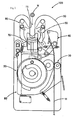
- Fig. 1 is a plan view showing a primary construction of a binding machine main body 100 according to an embodiment of the present invention.
- front part the part toward you in the drawings will be referred to as upper part.
- direction may be appropriately changed depending on the operation location.
- an opening 11, into which an item M to be tied (referred to as item M, hereinafter) can be inserted, is formed, and disposed in the rear part thereof is a rotating member 20.
- a tie feed mechanism 30, a cutter mechanism 40, a tie holding mechanism 50, a tie guide mechanism 60, a tying mechanism 70 and a switch mechanism 80 are driven according to the rotation of the rotating member 20.
- the power supply is turned on by the switch mechanism 80, the tie feed mechanism 30 feeds a tie-like member H toward the opening 11 and the tie holding mechanism 50 presses the tie-like member H from the front side against the item M.
- the cutter mechanism 40 cuts off the tie-like member H at a predetermined length, and the tie guide mechanism 60 turns the cut tie-like member H around the item M. Owing to this, the tying mechanism 70 ties the tie-like member H by twisting the both ends thereof.
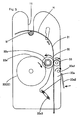
- the rotating member 20 is, as shown in Fig. 2, supported by a shaft 20a protruding upward from the base member 10, and the shaft 20a is driven to rotate clockwise by a motor (not shown) disposed below the base member 10.
- the rotating member 20 in which a drive cam 21 for the switch mechanism, a drive gear 22 for the tie feed mechanism, a drive cam 23 for the switch mechanism, a drive gear 24 for the cutter mechanism and the tying mechanism, and a drive cam 25 for the tie holding mechanism and the tie guide mechanism are pilled up in order from the top in a coaxial state, carries out a sequential tying operation while performing a rotation.
- Fig. 3 is a plan view showing a primary construction of the tie feed mechanism 30.
- a guide path 31 capable of guiding the tie-like member H, disposed between the guide path 31 and the rotating member 20 (drive gear 22) is a first tie feed roller 32, and disposed at the right side of the guide path 31 is a second tie feed roller 33.
- the first and second tie feed rollers 32 and 33 are respectively supported rotatably by a shaft vertically provided upward, and a rotation gear 32a integrally formed coaxially with the first tie feed roller 32 is meshed with a geared portion 22a of the drive gear 22 only in a specific period of time.
- the rotation gear 32a meshed with the geared portion 22a, rotates counterclockwise, and the first tie feed roller 32 rotates counterclockwise. Accordingly, the tie-like member H sandwiched between the first tie feed roller 32 and the second tie feed roller 33 is fed toward the front side of the base member 10 at a predetermined length by the turning forth of the first tie feed roller 32.
- predetermined length means a length that, when the tie-like member H has traversed the opening 11, the length from the front end thereof to a point where the tie like member H faces the item M is almost the same as the length from the point where the tie like member H faces the item M to a blade receiving member 41 (later described in a section of the cutter mechanism 40).
- the second tie feed roller 33 is supported by an operation lever 33a, which is disposed so as to be rotatable around a fixing pin 33a1 as the fulcrum thereof in Fig. 3; and the operation lever 33a is provided with a press operation piece 33a2 at a point right rear of the fixing pin 33a1, the rear end thereof is biased toward the right-rear by the pull spring 33a3.
- the operation lever 33a rotates clockwise and the second tie feed roller 33 is separated from the first tie feed roller 32. This permits to sandwich the tie-like member H between the first tie feed roller 32 and the second tie feed roller 33 so as to be ready to feed out the tie-like member H.
- Fig. 4 is a plan view showing a primary construction of the cutter mechanism 40.
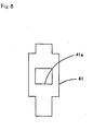
- a blade receiving member 41 shown in Fig. 5 Disposed at the right side of the opening 11 is a blade receiving member 41 shown in Fig. 5 , and an aperture 41a of the blade-receiving member 41 is positioned to interpose in the way of the guide path 31. Accordingly, the tie-like member H fed out from the tie feed mechanism 30 is supplied to the opening 11 through the aperture 41a of the blade-receiving member 41.
- a cutter member 42 Disposed movably forward/backward on the left surface of the blade receiving member 41 is a cutter member 42; the cutter member 42 waits at the front side of the aperture 41a while the tie-like member H is fed out from the tie feed mechanism 30, and when the feed out operation of the tie-like member H has completed, the cutter member 42 slides toward the rear side along the left surface of the blade receiving member 41 and closes the aperture 41a, thereby the tie-like member H is cut off.
- the cutter mechanism 40 has movable members 43-45, which are connected to each other, disposed therein.
- the movable member 43 has a roughly triangle-like shape and is supported rotatably by a pivot pin 43a in the apex at the front-right thereof. Also, in the apex at the front-left of the movable member 43, a vertically oriented support pin 43b is supported; and the cutter member 42 is supported by the support pin 43b.
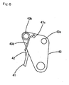
- the cutter member 42 is provided with a cutter blade 42a at the rear edge of a plate member having a roughly rectangular shape, and front end thereof is curled into a ring-like shape to form a support portion 42b.
- the cutter member 42 is supported rotatably by the movable member 43.
- a holder pin 43c is provided vertically upward at the front-right of the support pin 43b, and the front end of a spring member 43d, which is formed by coiling a wire once, is brought into contact with the left side of the holder pin 43c.
- the rear end of the spring member 43d is bent downward so that the front end is brought into contact with the left side face of the cutter member 42.
- the spring member 43d tends to make the front end and the rear end thereof displace rightward and leftward respectively. However, the front end is pressed from the right by the holder pin 43c; and the rear end is pressed from the right by the cutter member 42. At this time, since the position of the blade receiving member 41 is fixed by a side wall of a concave portion formed in the base member 10; and since the cutter member 42 is positioned in the right/left direction by the blade receiving member 41, the rear end of the spring member 43d is prevented from being displaced in the right/left direction by the cutter member 42.
- the movable member 45 has a roughly triangle-like shape, being supported rotatably by a pivot pin 45a in the apex at the front-left, and a pusher pin 45b protruding upward is provided in the apex of the rear part. Attached to the pusher pin 45b is a ring-like member 45b1, which is rotatable freely, and the ring-like member 45b1 always comes into contact with the periphery edge of the drive gear 24 . Also, rotatably connected to the apex at the front-right of the movable member 45 is the rear end of the movable member 44.
- the cutter mechanism 40 which has the construction, operates as shown in Fig. 7 to cut off the tie-like member H.
- the rotating member 20 further rotates, and when the convex portion 24a of the drive gear 24 retracts from the position where the convex portion 24a faces ring-like member 45b1, owing to the restoring force of the spring member 43d, the movable member 43 is forced to return clockwise. Accordingly, accompanying the return of the movable member 44 toward the rear side, the movable member 45 is forced to reverse clockwise to the initial position.
- a slide plate 12 disposed inside the base member 10 is a slide plate 12 having a roughly U-like shape and wing sides 12a and 12b with free end thereof being oriented to the front side respectively.
- a base side 12c of the slide plate 12 is disposed in the rear area of the drive cam 25.
- the front edge of the base side 12c and the inside edges of the wing sides 12a and 12b come into contact with a convex portion 25a formed on the drive cam 25.
- the inner edge of the right wing side 12a is formed with a step 12a1, and when moving from the front-left, the convex portion 25a comes into contact with the pusher face of the step 12a1 to push the slide plate 12 toward the rear side.
- formed in the inner edge of the left wing side 12b is a step 12b1.
- the convex portion 25a comes into contact with the pusher face of the step 12b1 to push the slide plate 12 toward the front side.
- a pair of elongated holes 12d and 12e are formed in the slide plate 12 in the front-rear direction, and guide pins 13 and 14 are provided vertically from the base member 10 being inserted into the elongated holes so as to allow the slide plate 12 to move in the front-rear direction.
- Fig. 8 shows a state at a point when the tie-like member H is fed up to a predetermined position by the tie feed mechanism 30.
- the convex portion 25a of the drive cam 25 comes into contact with the pusher face of the step 12a1 .
- the drive cam 25 turns further clockwise, since the convex portion 25a pushes the pusher face toward the rear side, the slide plate 12 shifts toward the rear side.
- each of the elongated holes 12d and 12e allows the respective guide pins 13 and 14 to shift relatively toward the front side. Accordingly, the slide plate 12 shifts toward the rear side while being positioned in the right-left direction as shown in Fig. 9.
- the tie holding mechanism 50 shown in Fig. 8 is driven to press the tie-like member H, which has been fed up to a predetermined position, to the item M from the front side as shown in Fig. 9.
- the tie holding mechanism 50 is provided with a rotation arm 51 formed with a tie holding portion 51a by bending the front end thereof upward as shown in Fig. 8.
- a pivot pin 15 provided vertically from the base member 10 rotatably supports the rear end of the rotation arm 51 disposed between the rear end of the rotation arm 51 and the right portion of the base member 10 is a pull spring 52.
- a convex portion 51b Formed on the rear-left edge portion of the rotation arm 51 is a convex portion 51b which can come into contact with the front end of a hook-like projection 12a2 extended from the left end of the right wing side 12a of the slide plate 12.
- the front end of the rotation arm 51 is turned clockwise and is received in an area at the right side of the opening 11.
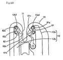
- pivot pins 61a and 62a Formed in the front end of the respective wing sides 12a and 12b of the slide plate 12 as shown in Fig. 8 and Fig. 9 are round holes 12a3 and 12b2 respectively. And inserted into the respective round holes 12a3 and 12b2, as shown in Fig. 10, are pivot pins 61a and 62a provided downward from each of the tie guide members 61 and 62. Also, when these pivot pins 61a and 62a are inserted into the respective round holes 12a3 and 12b2, the lower end portion thereof protrudes downward exceeding the slide plate, and is inserted into the guide grooves 16a and 16b respectively, which are formed in the base member 10 in the front/rear direction as shown in Fig. 8 and Fig. 9. Accordingly, when the slide plate 12 moves, the pivot pins 61a and 62a are guided in the front/rear direction by the guide grooves 16a and 16b.
- Each tie guide member 61, 62 is provided with tie guide portion 61b, 62b respectively having a bifurcated shape oriented toward the opening 11, and in the front end thereof, the a pivot pin 61a, 62a is disposed being protruding respectively, and in the rear end thereof, a guide pin 61c, 62c is disposed being protruding upward respectively.
- formed in the parts of the base member 10 above the tie guide members 61 and 62 are guide grooves 17a and 17b as shown in Fig. 11, and into these guide grooves 17a and 17b, guide pins 61c, 62c are inserted from the bottom.
- the guide grooves 17a and 17b constitute a guide mechanism according to the present invention.
- a ring-like member is mounted rotatably in the peripheral direction on the guide pins 61c and 62c respectively so as to allow smooth movement in the guide grooves 17a and 17b.
- each tie guide member 61, 62 is guided toward the rear side along with the slide plate 12.
- the tie guide members 61 and 62 move toward the rear side in parallel to each other without rotating while pressing the bifurcated portions formed on the tie guide portions 61b and 62b to the tie-like member H, and as shown in Fig. 12, the tie-like member H is turned around the periphery of the item M, and both ends of the tie-like member H are guided toward the rear side thereof.
- the guide grooves 17a and 17b are formed so that the front sides thereof are parallel to each other in the front/rear direction, and the rear sides thereof are curved toward the opening 11 respectively.
- Fig. 12 shows a state at a point when the guide pins 61c and 62c are guided up to the vicinity of the curved points of the guide grooves 17a and 17b.
- tie guide members 61 and 62 begin to rotate around the pivot pin 61a, 62a as the fulcrum respectively as shown in Fig. 13. That is, as shown in Fig. 13, the tie guide member 61 turns clockwise so that the tie-like member H is turned around the item M from the right side toward the rear side thereof; and the tie guide member 62 turns counterclockwise so that the tie-like member His turned around the item M from the left side toward the rear side thereof. Then, tie guide portions 61b and 62b of the tie guide members 61 and 62 are made closer to each other at the rear side of the item M, thereby both end sides of the tie-like member H are made closer to each other.
- a rectangular hole18 is formed in the rear side of the opening 11, and in the area from the rectangular hole 18 to the rotating member 20, the tying mechanism 70 is constituted.
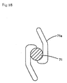
- a twist head 71a having a roughly S-like shape as shown in Fig. 15.
- a gear unit integrally formed on the rear end of the shaft 71 as shown in Fig. 14 is a gear unit in which a gear 71b is provided in the peripheral direction of the shaft 71.
- twist head 71a formed on the front end of the shaft 71 turns, the twist head 71a catches both end sides of the tie-like member H which have been turned around the item M by the tie guide mechanism 60, and twist them to tie the item M as shown in Fig. 14.
- the switch mechanism 80 for turning on the power supply to the motor to drive and rotate the shaft 20a of the rotating member 20 is provided.
- a movable member 81 Disposed in an area behind the recess of the opening 11 is a movable member 81, which has a rectangular opening 81a and is provided with an arm portion 81b extending toward the left side from the left side edge thereof. Formed in the front/rear direction in the arm portion 81b is an elongated hole 81b1. Into the elongated hole 81b1, guide pins 19a and 19b extending vertically from the base member 10 are inserted movably in the front/rear direction. Owing to this, when the item M is pressed to the recess of the opening 11, the movable member 81 becomes movable toward the rear side while being guided along the elongated hole 81b1 toward the rear side by the guide pins 19a and 19b.
- a pivot pin 81b2 protruding upward.
- the pivot pin 81b2 rotatably supports the front end of the oscillating arm 82.
- a convex portion 82a protruding rightward. It is arranged so that the convex portion 82a can come into contact with the drive cam 23.
- a pull spring 83 disposed between the right side of the front end of the oscillating arm 82 and the front side of the base member 10 is a pull spring 83.
- the pull spring 83 biases the oscillating arm 82 counterclockwise; thereby the convex portion 82a is pressed to a peripheral portion of the drive cam 23.
- a tact switch 84 Disposed on the base member 10 at the rear side of the oscillating arm 82 is a tact switch 84.
- a switch piece 84a of the tact switch 84 is disposed movably forward/backward at the rear side of the oscillating arm 82.
- a rotation member 85 Disposed in front of the tact switch 84 is a rotation member 85 having a roughly triangle shape, and the rotation member 85 is rotatably supported by a pivot pin 19c protruding upward from the base member 10. Also, it is arranged so that the apex at the front side of the rotation member 85 can come into contact with the drive cam 21, and provided to the apex at the left side of the rotation member 85 protruding upward is a press pin 85a which can come in contact with the switch piece 84a. Further, disposed in front of the pivot pin 19c and between the right side of the base member 10 and the same is a pull spring 86, and the rotation member 85 is always biased clockwise around the pivot pin 19c as the fulcrum.
- the movable member 81 moves the elongated hole 81b1 toward the rear side along the guide pins 19a and 19b and performs a parallel movement toward the rear side against the biasing force of the pull spring 83.
- the oscillating arm 82 also performs a parallel movement toward the rear side along with a movable member 81, and as shown in Fig. 18, the switch piece 84a is pressed toward the rear side by the rear end of the oscillating arm 82 causing the tact switch 84 to turn on.
- a concave portion 21a is formed in a part of the periphery edge of the drive cam 21, a concave portion 21a is formed.
- the rotation member 85 is biased clockwise around the pivot pin 19c as the fulcrum by the pull spring 86, thus the press pin 85a is separated away from the switch piece 84a.
- the apex at the front side of the rotation member 85 faces a portion where is higher by one step being interposed by a step formed at an end of the concave portion 21a of the drive cam 21. Then, the apex at the front side of the rotation member 85 is pressed leftward by the periphery edge portion of the drive cam 21, the rotation member 85 rotates counterclockwise around the pivot pin 19c as the fulcrum, and the press pin 85a presses the switch piece 84a toward the rear side along with the oscillating arm 82.
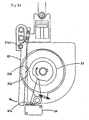
- the oscillating arm 82 rotates counterclockwise. However, since the rear end of the oscillating arm 82 comes into contact with the front end of the switch piece 84a, even in a state where the movable member 81 is pressed toward the rear side as shown in Fig. 22, the rear end of the oscillating arm 82 does not press the switch piece 84a toward the rear side. Accordingly, the tact switch 84 is remained being off.
- a protection cover 10a is provided to the upper face of the base member 10.
- the protection cover 10a is fixed by screws on the upper face of the base member 10 being interposed by spacers 10a1, which are longer in the axial direction than the height of the rotating member 20.
- through holes 10a2 and 10a3 for allowing the top ends of the shaft 20a and a shaft of the first tie feed roller 32.
- the shafts are maintained in the substantially vertical direction, and prevented from axial displacement.
- a through hole 10a4 is also formed in front of the through hole 10a2.
- a cylindrical member 10a5 is inserted into the through hole 10a4 by force. As shown in Fig. 24, it is arranged so that, while forming a slight space, the lower end of the cylindrical member 10a5 faces the upper face of the rotating member 20 . In order to prevent the rotating member 20 from running out of the horizontal plane, the cylindrical member 10a5 restricts the position of the upper face of the rotating member 20 by the lower end of the cylindrical member 10a5 to ensure the mesh between the gears 22a and 24b.
- the binding machine main body 100 having the construction is, as shown in Fig. 25, mounted on the upper part of a motor box 200 with the base member oriented in the roughly horizontal direction.
- a motor box 200 in addition to a drive motor, a power supply switch, a power supply circuit and the like are contained.
- the binding machine main body 100 is provided with a protection cover 300 so as to cover the entire from the top thereof, each member disposed on the base member 10 is protected from the outside.
- a tie-like member supply unit 500 for supplying a tie-like member H wound on a drum 400 to the binding machine main body.
- drum support arms 510 and 510 Provided on the back side face of the motor box 200 protruding therefrom at a distance slightly wider than the thickness of the drum 400 is a pair of drum support arms 510 and 510. In the upper sides in the front end side of the drum support arms 510 and 510, openings 510a and 510a are formed.
- a through hole 410 is formed in the axial direction, and into the through hole 410, an axel support member 420 is inserted therethrough. Since both ends of the axel support member 420 are inserted respectively into the openings 510a, 510a, the drum support arms 510, 510 support the drum 400 rotatably.
- a tension arm 520 Interposed between the feed out position of the tie-like member H in the drum 400 and the rear end of the binding machine is a tension arm 520.
- the lower end of the tension arm 520 is supported rotatably at a lower portion of the rear end of the motor box 200 so that the upper portion is biased in the rear-lower direction by the spring 521.
- a shaft 522 integrally provided at the upper end side of the tension arm 520 is a shaft 522 with the axis thereof oriented vertically with respect to the drawing.
- a rotating member 523 which has a roughly cylinder-like shape and a through hole in the axial direction, is inserted.
- the front end of the tie-like member H is fed out from a lower portion of the drum 400 to the binding machine main body 100 via the rotating member 523. Accordingly, when the tie feed mechanism 30 in the binding machine main body 100 feeds out the tie-like member H, the upper part of the tension arm 520 inclines forward against the biasing force of the spring 521. When the tie feed mechanism 30 does not feed out the tie-like member H, the upper part of the tension arm 520 is inclined toward the rear side by the biasing force of the spring 521 to remove a slack of the tie-like member H.
- a shaft 524 of which axis is oriented vertically with respect to the drawing Disposed in a lower part of the rotating member 523 in the tension arm 520 is a shaft 524 of which axis is oriented vertically with respect to the drawing. The purpose of this is, when the upper part of the tension arm 520 is inclined toward the rear side by the biasing force of the spring 521, to restrict the inclination angle of the tension arm 520 by allowing the shaft 524 to come into contact with the drum 400.
- an elastic member is provided to the shaft 524 so as to cover the peripheral surface thereof.
- the tie guide members 61 and 62 move toward the rear side parallel to each other at the sides of the opening 11, turn the tie-like member H around the periphery of the item M, and guide both end sides of the tie-like member H to the rear side thereof. Then, the tie guide members 61 and 62 turn respectively around the pivot pins 61a and 62a as the fulcrum and move to the rear side, and by making the tie guide portions 61b and 62b closer to each other at the rear part of the item M, the both end sides of the tie-like member H are made closer to each other.
- a binding machine with which an operator can carry out tying operation without sensation of fear.
- the present invention can provide a binding machine with which an operator can carry out tying operation without sensation of fear.
Landscapes
- Engineering & Computer Science (AREA)
- Mechanical Engineering (AREA)
- Basic Packing Technique (AREA)
- Seal Device For Vehicle (AREA)
Abstract
Description
- The present invention relates to a binding machine, and in particular, to a binding machine that ties an item to be tied (referred to as item, hereinafter) such as rod-like item using a tie-like member capable of tying by being twisted.
- There is known, as a conventional binding machine, the binding machine disclosed in
USP No. 4169346 . - The binding machine is provided with an opening available for inserting an item therein. A bifurcated arm is moved toward the recess of the opening so as to traverse the opening. Both ends of a tie-like member are guided toward the lower portion of the item by the front-end portions of the bifurcated arm; thereby the tie-like member is turned around the item. Thus, the both ends of the tie-like member are tied by being twisted.
- The conventional binding machine suffers from the problem in which when an operator carries out tying operation by inserting an item into the opening, since the bifurcated arm moves traversing the opening, the operator is given with sensation of fear.
- In view of the problem, an object of the present invention is to provide a binding machine with which an operator can carries out the tying operation with security.
- To attain the object, the invention of claim 1 resides in the construction that comprises: a base member having a bifurcated shape in the front side thereof, into which an item can be inserted; a tie feed mechanism that feeds out a tie-like member of a predetermined length in the width direction of the base member so as to transverse an opening formed between the bifurcations of the base member; a tie guide mechanism having a pair of tie guide members capable of moving respectively in the substantially front/rear direction of the base member at the side areas of the opening thereby to press the front end side and the fed-out end side of the tie-like member toward the rear side of the opening by the respective front end portions, and a guide mechanism that guides each tie guide member toward the rear side substantially parallel to the opening, and turns the respective front end portions around toward the rear side of the opening thereby to make the respective front end portions closer to each other at the rear side of the opening; and a tying mechanism, provided at the rear side of the opening, for tying by twisting both end sides of the tie-like member.
- According to the invention of claim 1 constructed as described above, when the tie feed mechanism feeds out a tie-like member of a predetermined length in the width direction of the base member so as to traverse the opening available for inserting an item therein, which opening is formed in the front side of the base member; the tie guide mechanism allows the guide mechanism, in the side areas of the opening, to guide a pair of tie guide members roughly parallel to the opening toward the rear side, and to turn the respective front end portions toward the rear side of the opening, and thereby making the respective front end portions closer to each other at the rear side of the opening.
- At this time, since the respective tie guide member presses the front end side and the fed-out end side respectively of the tie-like member by the respective front end portions thereof toward the rear side, and makes the tie-like member turn around the periphery of the item, the tying mechanism, provided in the rear side of the opening, twists to tie both end sides of the tie-like member.
- The above-described construction, in carrying out the tying operation of the item, allows the tie-like member to traverse the opening and does not allow the tie guide member to traverse the opening, thus freeing an operator who inserts the item into the opening from sensation of fear caused by the movement of the tie guide member.
- Here, the wording of "front side" means a relative position only when the base member is viewed as a whole. Accordingly, the orientation of the opening may be appropriately changed depending on the positioning of the base member.
- The tie feed mechanism, so long as it can feed a tie-like member of a predetermined length in the width direction so as to traverse the opening between the bifurcations of the base member, may be modified as: one mechanism where a continuously formed tie-like member may be cut and fed; and the other mechanism where a tie-like member, which has been previously cut, may be fed out. In the former case, in order to adjust the length of the tie-like member to be fed out, an adjusting mechanism may be provided depending on the necessity.
- As for the tie guide member, any guide member that is capable of moving in the roughly front/rear direction in the side areas of the opening, and pushing the front end side and the fed-out side end of the tie-like member with the respective front end parts thereof toward the rear side may be adopted. As an example of the construction, the invention according to claim 2 has such construction that in the binding machine set forth in the claim 1, each of the tie guide members is supported by a movable member which is driven together in the front/rear direction.
- According to the invention of claim 2 constructed as described above, when the movable members are driven in the front/rear direction, each of the tie guide members supported by the movable members moves together forward/backward. According to claim 2, the construction is simplified by arranging so as to support each of the tie guide members with the same member to move them forward/backward. However, the construction is just an example. Each of the tie guide members may be moved forward/backward separately.
- As for the guide mechanism, any guide mechanism may be adopted so long as it guides each of the tie guide members roughly parallel to the opening toward the rear side, turns the respective front ends toward the rear side of the opening thereby to make the respective front ends closer to each other at the rear side of the opening. As an example of the construction, the invention according to claim 3 has such construction that, in a binding machine set forth in claim 1 or 2, the guide mechanism is provided with a concavo-convex structure. The concavo-convex structure, formed between the base member and the respective tie guide members, is constructed such that: in the front side of the base member, moves the tie guide members toward the rear side roughly parallel to the opening portion; and in the rear side of the base member, turns the respective front end portions of the tie guide member around toward the rear side of the opening thereby to make each front ends closer to each other at the rear side of the opening.
- According to the invention of claim 3 constructed as described above, the concavo-convex guide structure, formed between the base member and the respective tie guide members, guides in the front side of the base member, the tie guide member toward the rear side roughly parallel to the opening portion; and in the rear side, turns the respective front-end portions of the tie guide member toward the rear side of the opening thereby to make the respective front end portions closer to each other at the rear side of the opening.
-
- Fig. 1 is a plan view showing a primary construction of a binding machine main body according to an embodiment of the present invention.
- Fig. 2 is a plan view showing a construction of a rotating member.
- Fig. 3 is a plan view showing a primary construction of a tie feed mechanism.
- Fig. 4 is a plan view showing a primary construction of a cutter mechanism.
- Fig. 5 is a plan view showing a construction of a blade-receiving member.
- Fig. 6 is a plan view showing a primary construction in a cutter member holding portion.
- Fig. 7 is a plan view showing a cutter mechanism when a tie-like member is cut off.
- Fig. 8 is a plan view showing a positional relationship between a slide plate and a rotation arm when a tie-like member is fed up to a predetermined position by the tie feed mechanism.
- Fig. 9 is a plan view showing a positional relationship between the slide plate and the rotation arm when a tie holding portion holds the tie-like member.
- Fig. 10 is a plan view showing a state where a tie guide member is mounted to the slide plate.
- Fig. 11 is a plan view showing the operation of the tie guide member from the initial state.
- Fig. 12 is a plan view showing the operation of the tie guide member when both end sides of the tie-like member is guided backward.
- Fig. 13 is a plan view showing the operation of the tie guide member when both end sides of the tie-like member are turned toward the back of an item.
- Fig. 14 is a plan view showing a primary construction of a tying mechanism.
- Fig. 15 is a sectional view showing a construction of a twist head.
- Fig. 16 is a sectional view showing a gearing state between a drive gear and a gearbox.
- Fig. 17 is a plan view showing the operation of a switch mechanism from the initial state.
- Fig. 18 is a plan view showing a state when an oscillating arm has pressed a switch piece.
- Fig. 19 is a plan view showing a state when a press pin has pressed the switch piece.
- Fig. 20 is a plan view showing a state when the pressure of the switch piece by the press pin has been released.
- Fig. 21 is a plan view showing a state when the oscillating arm has been pressed leftward by a drive cam.
- Fig. 22 is a plan view showing a switch mechanism when a sequence of tying operation has completed.
- Fig. 23 is a plan view illustrating an additional construction in a protection cover.
- Fig. 24 is a sectional view showing a positional relationship between a cylindrical member attached to the protection cover and the rotating member.
- Fig. 25 is a side view showing the entire construction of the binding machine.
- Herein, an embodiment of the present invention will be described in the following order.
- (1) outline of binding machine main body:
- (2) tie feed mechanism:
- (3) cutter mechanism:
- (4) tie holding mechanism:
- (5) tie guide mechanism:
- (6) tying mechanism:
- (7) switch mechanism:
- (8) chattering preventive structure:
- (9) outline of entire binding machine:
- Fig. 1 is a plan view showing a primary construction of a binding machine
main body 100 according to an embodiment of the present invention. Hereafter, the upper part of the drawings will be referred to as front part; the part toward you in the drawings will be referred to as upper part. However, the direction may be appropriately changed depending on the operation location. - In the front part of a
base member 10, anopening 11, into which an item M to be tied (referred to as item M, hereinafter) can be inserted, is formed, and disposed in the rear part thereof is a rotatingmember 20. Also, provided to thebase member 10 are atie feed mechanism 30, acutter mechanism 40, atie holding mechanism 50, atie guide mechanism 60, a tyingmechanism 70 and aswitch mechanism 80, which are driven according to the rotation of the rotatingmember 20. - Owing to the construction, when an item M is inserted into the
opening 11, the power supply is turned on by theswitch mechanism 80, thetie feed mechanism 30 feeds a tie-like member H toward theopening 11 and thetie holding mechanism 50 presses the tie-like member H from the front side against the item M. - Then, the
cutter mechanism 40 cuts off the tie-like member H at a predetermined length, and thetie guide mechanism 60 turns the cut tie-like member H around the item M. Owing to this, the tyingmechanism 70 ties the tie-like member H by twisting the both ends thereof. - The rotating
member 20 is, as shown in Fig. 2, supported by ashaft 20a protruding upward from thebase member 10, and theshaft 20a is driven to rotate clockwise by a motor (not shown) disposed below thebase member 10. - The rotating
member 20, in which adrive cam 21 for the switch mechanism, adrive gear 22 for the tie feed mechanism, adrive cam 23 for the switch mechanism, adrive gear 24 for the cutter mechanism and the tying mechanism, and adrive cam 25 for the tie holding mechanism and the tie guide mechanism are pilled up in order from the top in a coaxial state, carries out a sequential tying operation while performing a rotation. - Fig. 3 is a plan view showing a primary construction of the
tie feed mechanism 30. - Formed on the
base member 10 from a right-rear portion thereof toward theopening 11 is aguide path 31 capable of guiding the tie-like member H, disposed between theguide path 31 and the rotating member 20 (drive gear 22) is a firsttie feed roller 32, and disposed at the right side of theguide path 31 is a secondtie feed roller 33. - The first and second
tie feed rollers rotation gear 32a integrally formed coaxially with the firsttie feed roller 32 is meshed with a gearedportion 22a of thedrive gear 22 only in a specific period of time. - Owing to the construction, when the
drive gear 22 rotates clockwise, therotation gear 32a, meshed with the gearedportion 22a, rotates counterclockwise, and the firsttie feed roller 32 rotates counterclockwise. Accordingly, the tie-like member H sandwiched between the firsttie feed roller 32 and the secondtie feed roller 33 is fed toward the front side of thebase member 10 at a predetermined length by the turning forth of the firsttie feed roller 32. Here, the wording "predetermined length" means a length that, when the tie-like member H has traversed theopening 11, the length from the front end thereof to a point where the tie like member H faces the item M is almost the same as the length from the point where the tie like member H faces the item M to a blade receiving member 41 (later described in a section of the cutter mechanism 40). - The second
tie feed roller 33 is supported by anoperation lever 33a, which is disposed so as to be rotatable around a fixing pin 33a1 as the fulcrum thereof in Fig. 3; and theoperation lever 33a is provided with a press operation piece 33a2 at a point right rear of the fixing pin 33a1, the rear end thereof is biased toward the right-rear by the pull spring 33a3. - Accordingly, when the press operation piece 33a2 is pressed leftward against the biasing force of the pull spring 33a3, the
operation lever 33a rotates clockwise and the secondtie feed roller 33 is separated from the firsttie feed roller 32. This permits to sandwich the tie-like member H between the firsttie feed roller 32 and the secondtie feed roller 33 so as to be ready to feed out the tie-like member H. - Fig. 4 is a plan view showing a primary construction of the
cutter mechanism 40. - Disposed at the right side of the
opening 11 is ablade receiving member 41 shown in Fig. 5 , and anaperture 41a of the blade-receivingmember 41 is positioned to interpose in the way of theguide path 31. Accordingly, the tie-like member H fed out from thetie feed mechanism 30 is supplied to theopening 11 through theaperture 41a of the blade-receivingmember 41. - Disposed movably forward/backward on the left surface of the
blade receiving member 41 is acutter member 42; thecutter member 42 waits at the front side of theaperture 41a while the tie-like member H is fed out from thetie feed mechanism 30, and when the feed out operation of the tie-like member H has completed, thecutter member 42 slides toward the rear side along the left surface of theblade receiving member 41 and closes theaperture 41a, thereby the tie-like member H is cut off. - As described above, in order to move the
cutter member 42 forward/backward at a predetermined timing, thecutter mechanism 40 has movable members 43-45, which are connected to each other, disposed therein. Themovable member 43 has a roughly triangle-like shape and is supported rotatably by apivot pin 43a in the apex at the front-right thereof. Also, in the apex at the front-left of themovable member 43, a vertically orientedsupport pin 43b is supported; and thecutter member 42 is supported by thesupport pin 43b. - The
cutter member 42 is provided with acutter blade 42a at the rear edge of a plate member having a roughly rectangular shape, and front end thereof is curled into a ring-like shape to form asupport portion 42b. By inserting thesupport pin 43b into thesupport portion 42b, thecutter member 42 is supported rotatably by themovable member 43. - Further, to the
movable member 43, as shown in Fig. 6, aholder pin 43c is provided vertically upward at the front-right of thesupport pin 43b, and the front end of aspring member 43d, which is formed by coiling a wire once, is brought into contact with the left side of theholder pin 43c. The rear end of thespring member 43d is bent downward so that the front end is brought into contact with the left side face of thecutter member 42. - Owing to the construction, the
spring member 43d tends to make the front end and the rear end thereof displace rightward and leftward respectively. However, the front end is pressed from the right by theholder pin 43c; and the rear end is pressed from the right by thecutter member 42. At this time, since the position of theblade receiving member 41 is fixed by a side wall of a concave portion formed in thebase member 10; and since thecutter member 42 is positioned in the right/left direction by theblade receiving member 41, the rear end of thespring member 43d is prevented from being displaced in the right/left direction by thecutter member 42. - Accordingly, when the
movable member 43 turns counterclockwise around thepivot pin 43a as the fulcrum, since the front end of thespring member 43d displaces leftward, thespring member 43d deforms so that both of the front and rear ends are separated from each other. Then, on thespring member 43d, such biasing force that presses back the both front and rear ends in the direction to be closer to each other to return to the initial configuration thereof is generated. In the apex at the rear-right of themovable member 43, the front end of themovable member 44 is connected movably. - On the other hand, likewise the
movable member 45 has a roughly triangle-like shape, being supported rotatably by apivot pin 45a in the apex at the front-left, and apusher pin 45b protruding upward is provided in the apex of the rear part. Attached to thepusher pin 45b is a ring-like member 45b1, which is rotatable freely, and the ring-like member 45b1 always comes into contact with the periphery edge of thedrive gear 24 . Also, rotatably connected to the apex at the front-right of themovable member 45 is the rear end of themovable member 44. - The
cutter mechanism 40, which has the construction, operates as shown in Fig. 7 to cut off the tie-like member H. - That is, when the rotating
member 20 rotates clockwise, aconvex portion 24a formed on thedrive gear 24 faces the ring-like member 45b1, and when thepusher pin 45b is pushed rightward accompanying the rotation of thedrive gear 24, themovable member 45 rotates counterclockwise around thepivot pin 45a as the fulcrum. Then, since themovable member 44 is pushed up toward the front-right, themovable member 43 also rotates counterclockwise around thepivot pin 43a as the fulcrum against the biasing force of thespring member 43d. Accordingly, accompanying the displacement of thesupport pin 43b toward the rear side, thecutter member 42 moves to the rear side along the left surface of theblade receiving member 41 and cuts off the tie-like member H while traversing theaperture 41a. - The rotating
member 20 further rotates, and when theconvex portion 24a of thedrive gear 24 retracts from the position where theconvex portion 24a faces ring-like member 45b1, owing to the restoring force of thespring member 43d, themovable member 43 is forced to return clockwise. Accordingly, accompanying the return of themovable member 44 toward the rear side, themovable member 45 is forced to reverse clockwise to the initial position. - As shown in Fig. 8, disposed inside the
base member 10 is aslide plate 12 having a roughly U-like shape andwing sides base side 12c of theslide plate 12 is disposed in the rear area of thedrive cam 25. - It is arranged so that the front edge of the
base side 12c and the inside edges of the wing sides 12a and 12b come into contact with aconvex portion 25a formed on thedrive cam 25. The inner edge of theright wing side 12a is formed with a step 12a1, and when moving from the front-left, theconvex portion 25a comes into contact with the pusher face of the step 12a1 to push theslide plate 12 toward the rear side. On the other hand, formed in the inner edge of theleft wing side 12b is a step 12b1. When moving from the rear-right, theconvex portion 25a comes into contact with the pusher face of the step 12b1 to push theslide plate 12 toward the front side. - Also, formed in the
slide plate 12 in the front-rear direction are a pair ofelongated holes pins base member 10 being inserted into the elongated holes so as to allow theslide plate 12 to move in the front-rear direction. - Fig. 8 shows a state at a point when the tie-like member H is fed up to a predetermined position by the
tie feed mechanism 30. In this state, theconvex portion 25a of thedrive cam 25 comes into contact with the pusher face of the step 12a1 . Here, when thedrive cam 25 turns further clockwise, since theconvex portion 25a pushes the pusher face toward the rear side, theslide plate 12 shifts toward the rear side. At this time, each of theelongated holes slide plate 12 shifts toward the rear side while being positioned in the right-left direction as shown in Fig. 9. - Then, when the rotation of the
drive cam 25 proceeds and theconvex portion 25a comes into contact with the step 12b1 as shown with double-dashed line in Fig. 9, since the step 12b1 pushes the pusher face toward the front side this time, theslide plate 12 is made to shift toward the front side. At this time, since each of theelongated holes slide plate 12 shifts toward the front side while being positioned in the right-left direction as shown with double-dashed line in Fig. 8. - Thus, when the
slide plate 12 moves in the front-rear direction, thetie holding mechanism 50 shown in Fig. 8 is driven to press the tie-like member H, which has been fed up to a predetermined position, to the item M from the front side as shown in Fig. 9. - The
tie holding mechanism 50 is provided with arotation arm 51 formed with atie holding portion 51a by bending the front end thereof upward as shown in Fig. 8. Apivot pin 15 provided vertically from thebase member 10 rotatably supports the rear end of therotation arm 51 disposed between the rear end of therotation arm 51 and the right portion of thebase member 10 is apull spring 52. - Formed on the rear-left edge portion of the
rotation arm 51 is aconvex portion 51b which can come into contact with the front end of a hook-like projection 12a2 extended from the left end of theright wing side 12a of theslide plate 12. When theslide plate 12 is positioned at the front side, since theconvex portion 51b is pushed toward the front side by the front end of the hook-like projection 12a2 against the biasing force of thepull spring 52 as shown in Fig. 8, the front end of therotation arm 51 is turned clockwise and is received in an area at the right side of theopening 11. - On the other hand, when the
slide plate 12 is positioned at the rear side, since the press to theconvex portion 51b by the front end of the hook-like projection 12a2 is eliminated, the front end of therotation arm 51 rotates counterclockwise by the restoring force of thepull spring 52 and extends over theopening 11 as shown in Fig. 9. At this time, as shown in Fig. 9, when the item M is being inserted up to the recess of theopening 11, thetie holding portion 51a presses the tie-like member H, which is fed in front of the item M, to the item M from the front side. Then, at the point when thetie holding mechanism 50 is driven, since the tie-like member H is in a state where the same has been fed up to a predetermined position, as described above, a central portion thereof from the front end to theblade receiving member 41 is pressed to the item M. - Formed in the front end of the
respective wing sides slide plate 12 as shown in Fig. 8 and Fig. 9 are round holes 12a3 and 12b2 respectively. And inserted into the respective round holes 12a3 and 12b2, as shown in Fig. 10, arepivot pins tie guide members guide grooves base member 10 in the front/rear direction as shown in Fig. 8 and Fig. 9. Accordingly, when theslide plate 12 moves, the pivot pins 61a and 62a are guided in the front/rear direction by theguide grooves - Each
tie guide member tie guide portion opening 11, and in the front end thereof, the apivot pin guide pin base member 10 above thetie guide members guide grooves guide grooves guide grooves guide grooves - Owing to the construction, as shown in Fig. 11, when the
slide plate 12 moves toward the rear side, eachtie guide member slide plate 12. At this time, since the guide pins 61c and 62c are guided along theguide grooves tie guide members tie guide portions - The
guide grooves opening 11 respectively. Fig. 12 shows a state at a point when the guide pins 61c and 62c are guided up to the vicinity of the curved points of theguide grooves - From this point, when the
slide plate 12 further moves toward the rear side, since the guide pins 61c and 62c moves toward theopening 11 along theguide grooves tie guide members pivot pin tie guide member 61 turns clockwise so that the tie-like member H is turned around the item M from the right side toward the rear side thereof; and thetie guide member 62 turns counterclockwise so that the tie-like member His turned around the item M from the left side toward the rear side thereof. Then,tie guide portions tie guide members - When the
slide plate 12 move toward the front side, after being guided up to the vicinity of the curve of theguide grooves tie guide members - In the
base member 10, as shown in Fig. 14, a rectangular hole18 is formed in the rear side of theopening 11, and in the area from therectangular hole 18 to the rotatingmember 20, the tyingmechanism 70 is constituted. - Disposed between the
rectangular hole 18 and the rotatingmember 20 is ashaft 71 of which axis is oriented in the front/rear direction. Integrally formed on the front end of theshaft 71 is atwist head 71a having a roughly S-like shape as shown in Fig. 15. Also, integrally formed on the rear end of theshaft 71 as shown in Fig. 14 is a gear unit in which agear 71b is provided in the peripheral direction of theshaft 71. - Since it is arranged so that a
gear 24b formed in a part of the peripheral lower face of thedrive gear 24 can be meshed with thegear 71b as shown in Fig. 16, theshaft 71 rotates in the predetermined directions when thegear 24b is turned in the right/left direction accompanying the rotation of thedrive gear 24. - Then, since also the
twist head 71a formed on the front end of theshaft 71 turns, thetwist head 71a catches both end sides of the tie-like member H which have been turned around the item M by thetie guide mechanism 60, and twist them to tie the item M as shown in Fig. 14. - In the
base member 10, as shown in Fig. 17, from the recess of theopening 11 to the left rear end, theswitch mechanism 80 for turning on the power supply to the motor to drive and rotate theshaft 20a of the rotatingmember 20 is provided. - Disposed in an area behind the recess of the
opening 11 is amovable member 81, which has arectangular opening 81a and is provided with anarm portion 81b extending toward the left side from the left side edge thereof. Formed in the front/rear direction in thearm portion 81b is an elongated hole 81b1. Into the elongated hole 81b1, guide pins 19a and 19b extending vertically from thebase member 10 are inserted movably in the front/rear direction. Owing to this, when the item M is pressed to the recess of theopening 11, themovable member 81 becomes movable toward the rear side while being guided along the elongated hole 81b1 toward the rear side by the guide pins 19a and 19b. - Provide at the left-rear end of the
arm portion 81b is a pivot pin 81b2 protruding upward. The pivot pin 81b2 rotatably supports the front end of theoscillating arm 82. Also, formed on the right side face of theoscillating arm 82 is aconvex portion 82a protruding rightward. It is arranged so that theconvex portion 82a can come into contact with thedrive cam 23. Further, disposed between the right side of the front end of theoscillating arm 82 and the front side of thebase member 10 is apull spring 83. Thepull spring 83 biases theoscillating arm 82 counterclockwise; thereby theconvex portion 82a is pressed to a peripheral portion of thedrive cam 23. - Disposed on the
base member 10 at the rear side of theoscillating arm 82 is atact switch 84. Aswitch piece 84a of thetact switch 84 is disposed movably forward/backward at the rear side of theoscillating arm 82. - Disposed in front of the
tact switch 84 is arotation member 85 having a roughly triangle shape, and therotation member 85 is rotatably supported by apivot pin 19c protruding upward from thebase member 10. Also, it is arranged so that the apex at the front side of therotation member 85 can come into contact with thedrive cam 21, and provided to the apex at the left side of therotation member 85 protruding upward is apress pin 85a which can come in contact with theswitch piece 84a. Further, disposed in front of thepivot pin 19c and between the right side of thebase member 10 and the same is apull spring 86, and therotation member 85 is always biased clockwise around thepivot pin 19c as the fulcrum. - Owing to the construction, as shown in Fig. 17, when the item M is pressed to the recess of the
opening 11, since the front end portion of themovable member 81 is pressed toward the rear side by the item M, themovable member 81 moves the elongated hole 81b1 toward the rear side along the guide pins 19a and 19b and performs a parallel movement toward the rear side against the biasing force of thepull spring 83. Owing to this arrangement, theoscillating arm 82 also performs a parallel movement toward the rear side along with amovable member 81, and as shown in Fig. 18, theswitch piece 84a is pressed toward the rear side by the rear end of theoscillating arm 82 causing thetact switch 84 to turn on. - In a part of the periphery edge of the
drive cam 21, aconcave portion 21a is formed. When the apex at the front side of therotation member 85 faces theconcave portion 21a as shown in Fig.17, therotation member 85 is biased clockwise around thepivot pin 19c as the fulcrum by thepull spring 86, thus thepress pin 85a is separated away from theswitch piece 84a. - However, when the
tact switch 84 is turned on and thedrive cam 21 turns clockwise, as shown in Fig. 19, the apex at the front side of therotation member 85 faces a portion where is higher by one step being interposed by a step formed at an end of theconcave portion 21a of thedrive cam 21. Then, the apex at the front side of therotation member 85 is pressed leftward by the periphery edge portion of thedrive cam 21, therotation member 85 rotates counterclockwise around thepivot pin 19c as the fulcrum, and thepress pin 85a presses theswitch piece 84a toward the rear side along with theoscillating arm 82. - Accordingly, at this point, even when the press of the
movable member 81 by the item M is released and theoscillating arm 82 is returned toward the front side by the restoring force of thepull spring 83 and thus the press of theswitch piece 84a is released, since the press of theswitch piece 84a by thepress pin 85a is continued, thetact switch 84 is not turned off until the sequential tying operation by thetie feed mechanism 30, thecutter mechanism 40, thetie holding mechanism 50, thetie guide mechanism 60 and the tyingmechanism 70 is completed. - When the rotation of the
drive cam 21 further proceeds and the sequential tying operation has been completed, since the apex at the front side of therotation member 85 falls into theconcave portion 21a as shown in Fig. 20, the leftward press to the apex at the front side of therotation member 85 is released. Then, due to the restoring force by thepull spring 86, therotation member 85 rotates clockwise around thepivot pin 19c as the fulcrum, and thus the press to theswitch piece 84a by thepress pin 85a is eliminated. - Also, when a
convex portion 23a formed on thedrive cam 23 faces theconvex portion 82a as shown in Fig. 21, sinceconvex portion 23a pushes theconvex portion 82a leftward, theoscillating arm 82 rotates clockwise around the pivot pin 82b2 as the fulcrum and moves toward the left side of theswitch piece 84a, thus thetact switch 84 is turned off. - Then, when the
convex portion 23a move away from the point where the same faces theconvex portion 82a, due to elimination of leftward press by theconvex portion 23a, theoscillating arm 82 rotates counterclockwise. However, since the rear end of theoscillating arm 82 comes into contact with the front end of theswitch piece 84a, even in a state where themovable member 81 is pressed toward the rear side as shown in Fig. 22, the rear end of theoscillating arm 82 does not press theswitch piece 84a toward the rear side. Accordingly, thetact switch 84 is remained being off. - In the binding machine
main body 100 according to the embodiment of the present invention, in addition to the construction relevant to the tying operation, various arrangements are made. - For example, as shown in Fig. 23, in order to protect the rotating
member 20 from the top, aprotection cover 10a is provided to the upper face of thebase member 10. Theprotection cover 10a is fixed by screws on the upper face of thebase member 10 being interposed by spacers 10a1, which are longer in the axial direction than the height of the rotatingmember 20. - Here, formed at the center and the right end side of the
protection cover 10a are through holes 10a2 and 10a3 for allowing the top ends of theshaft 20a and a shaft of the firsttie feed roller 32. By allowing the top ends of the respective shafts to go through these through holes 10a2 and 10a3, the shafts are maintained in the substantially vertical direction, and prevented from axial displacement. - In the
protection cover 10a, a through hole 10a4 is also formed in front of the through hole 10a2. A cylindrical member 10a5 is inserted into the through hole 10a4 by force. As shown in Fig. 24, it is arranged so that, while forming a slight space, the lower end of the cylindrical member 10a5 faces the upper face of the rotatingmember 20 . In order to prevent the rotatingmember 20 from running out of the horizontal plane, the cylindrical member 10a5 restricts the position of the upper face of the rotatingmember 20 by the lower end of the cylindrical member 10a5 to ensure the mesh between thegears - The binding machine
main body 100 having the construction is, as shown in Fig. 25, mounted on the upper part of amotor box 200 with the base member oriented in the roughly horizontal direction. In themotor box 200, in addition to a drive motor, a power supply switch, a power supply circuit and the like are contained. - Here, since the binding machine
main body 100 is provided with aprotection cover 300 so as to cover the entire from the top thereof, each member disposed on thebase member 10 is protected from the outside. - Attached to the rear part of the
motor box 200 is a tie-likemember supply unit 500 for supplying a tie-like member H wound on adrum 400 to the binding machine main body. - Provided on the back side face of the
motor box 200 protruding therefrom at a distance slightly wider than the thickness of thedrum 400 is a pair ofdrum support arms drum support arms openings - In the
drum 400, a throughhole 410 is formed in the axial direction, and into the throughhole 410, anaxel support member 420 is inserted therethrough. Since both ends of theaxel support member 420 are inserted respectively into theopenings drum support arms drum 400 rotatably. - Interposed between the feed out position of the tie-like member H in the
drum 400 and the rear end of the binding machine is atension arm 520. The lower end of thetension arm 520 is supported rotatably at a lower portion of the rear end of themotor box 200 so that the upper portion is biased in the rear-lower direction by thespring 521. - Also, integrally provided at the upper end side of the
tension arm 520 is ashaft 522 with the axis thereof oriented vertically with respect to the drawing. Into theshaft 522, a rotatingmember 523, which has a roughly cylinder-like shape and a through hole in the axial direction, is inserted. - Owing to the construction, the front end of the tie-like member H is fed out from a lower portion of the
drum 400 to the binding machinemain body 100 via the rotatingmember 523. Accordingly, when thetie feed mechanism 30 in the binding machinemain body 100 feeds out the tie-like member H, the upper part of thetension arm 520 inclines forward against the biasing force of thespring 521. When thetie feed mechanism 30 does not feed out the tie-like member H, the upper part of thetension arm 520 is inclined toward the rear side by the biasing force of thespring 521 to remove a slack of the tie-like member H. - Disposed in a lower part of the rotating
member 523 in thetension arm 520 is ashaft 524 of which axis is oriented vertically with respect to the drawing. The purpose of this is, when the upper part of thetension arm 520 is inclined toward the rear side by the biasing force of thespring 521, to restrict the inclination angle of thetension arm 520 by allowing theshaft 524 to come into contact with thedrum 400. - Further, in order to avoid giving shock to the
drum 400 when theshaft 524 comes into contact with thedrum 400, an elastic member is provided to theshaft 524 so as to cover the peripheral surface thereof. - As described above, in the tie guide mechanism according to the embodiment of the present invention, the
tie guide members opening 11, turn the tie-like member H around the periphery of the item M, and guide both end sides of the tie-like member H to the rear side thereof. Then, thetie guide members tie guide portions - As described above, the present invention can provide a binding machine with which an operator can carry out tying operation without sensation of fear.
- Also, according to the inventions concerning claims 2 and 3, the construction of the tie guide mechanism can be simplified.
Claims (3)
- A binding machine comprising:a base member (10) having a bifurcated shape in the front side thereof, into which an item (m) to be tied (referred to as item, hereinafter) can be inserted;a tie feed mechanism (30) that feeds out a tie-like member of a predetermined length in the width direction of the base member so as to transverse an opening (11) formed between the bifurcations of said base member (10);a tie guide mechanism (60) having a pair of tie guide members (61, 62); anda tying mechanism (70), provided at a rear side of said opening, for tying by twisting both end sides of said tie-like member, characterised in that:said tie guide members are capable of moving respectively in the substantially front/rear direction at side areas of said opening thereby to press a front end side and a fed-out end side of said tie-like member toward the rear side of the opening by respective front end portions (61b, 62b), andthe tie guide mechanism further comprises a guide mechanism (17a, 17b, 61a, 62a, 61c, 62c) that guides each tie guide member (61, 62) toward the rear side of the opening substantially parallel to the opening and turns the respective front end portions around toward the rear side of the opening thereby to make the respective front end portions closer to each other at the rear side of the opening.
- The binding machine according to claim 1, wherein each of the tie guide members is supported by a movable member which is driven together in the front/rear direction.
- The binding machine according to claim 1 or 2, wherein said guide mechanism is provided with a concavo-convex structure, which is formed between said base member and the respective tie guide members, and in the front side thereof, moves the tie guide members toward the rear side roughly parallel to said opening portion, and in the rear side, turns the respective front end portions of the tie guide member around toward the rear side of the opening thereby to make the front ends closer to each other at the rear side of the opening.
Applications Claiming Priority (3)
| Application Number | Priority Date | Filing Date | Title |
|---|---|---|---|
| JP2001082291 | 2001-03-22 | ||
| JP2001082291A JP2002284111A (en) | 2001-03-22 | 2001-03-22 | Binding machine |
| PCT/JP2002/001990 WO2002076831A1 (en) | 2001-03-22 | 2002-03-04 | Binding machine |
Publications (3)
| Publication Number | Publication Date |
|---|---|
| EP1380507A1 EP1380507A1 (en) | 2004-01-14 |
| EP1380507A4 EP1380507A4 (en) | 2004-08-25 |
| EP1380507B1 true EP1380507B1 (en) | 2007-10-10 |
Family
ID=18938252
Family Applications (1)
| Application Number | Title | Priority Date | Filing Date |
|---|---|---|---|
| EP02705076A Expired - Lifetime EP1380507B1 (en) | 2001-03-22 | 2002-03-04 | Binding machine |
Country Status (11)
| Country | Link |
|---|---|
| US (1) | US7013614B2 (en) |
| EP (1) | EP1380507B1 (en) |
| JP (1) | JP2002284111A (en) |
| KR (1) | KR100817196B1 (en) |
| CN (1) | CN1245309C (en) |
| AT (1) | ATE375299T1 (en) |
| DE (1) | DE60222877T2 (en) |
| DK (1) | DK1380507T3 (en) |
| ES (1) | ES2294105T3 (en) |
| TW (1) | TW521056B (en) |
| WO (1) | WO2002076831A1 (en) |
Families Citing this family (11)
| Publication number | Priority date | Publication date | Assignee | Title |
|---|---|---|---|---|
| JP2006036231A (en) * | 2004-07-23 | 2006-02-09 | Shino Tange | Tie device |
| TWI443047B (en) * | 2008-03-27 | 2014-07-01 | Max Co Ltd | Bundle device |
| JP4858488B2 (en) * | 2008-05-19 | 2012-01-18 | マックス株式会社 | Rebar binding machine |
| KR101053831B1 (en) | 2009-02-05 | 2011-08-04 | 전석호 | Tie binding machine |
| CN102285465B (en) * | 2011-05-11 | 2013-03-13 | 江西长江化工有限责任公司 | Balance body binding device of limited space launcher |
| DE102012005764A1 (en) * | 2012-03-23 | 2013-09-26 | Deere & Company | binding device |
| CN110921004B (en) * | 2019-12-12 | 2021-09-03 | 郑晓华 | Automatic wire binding machine for lollipops |
| CN111409890B (en) * | 2020-01-12 | 2025-02-11 | 深圳市农科创网络有限公司 | Strapping machine and method of using the same |
| CN112389761A (en) * | 2020-12-03 | 2021-02-23 | 兰州大学 | Open-air sample encapsulation machine of gathering |
| JP7661762B2 (en) * | 2021-04-16 | 2025-04-15 | マックス株式会社 | Binding machine |
| CN115416913B (en) * | 2022-09-30 | 2024-04-12 | 征图新视(江苏)科技股份有限公司 | Fresh flower stalk binding device |
Family Cites Families (25)
| Publication number | Priority date | Publication date | Assignee | Title |
|---|---|---|---|---|
| CH49675A (en) | 1909-08-06 | 1911-03-16 | Jules Jouffret Henri Victor | Carburetor |
| US1400327A (en) * | 1920-10-23 | 1921-12-13 | Charles F Sparks | Bag closing and tying machine |
| US2478435A (en) | 1946-02-23 | 1949-08-09 | Columbia Malting Company | Apparatus for applying bag ties |
| FR1215076A (en) | 1958-11-04 | 1960-04-13 | Successeurs De B Trayvou | Machine for ligating and labeling sachets or the like |
| GB1079356A (en) | 1964-06-08 | 1967-08-16 | Harry Sigurd Valdemar Jaerund | Closing and labelling bags and like packages |
| US3369573A (en) * | 1964-10-23 | 1968-02-20 | Royal Industries | Tying apparatus |
| DE1786506A1 (en) | 1967-03-23 | 1972-05-04 | D B M S R L Di Della Bella Ita | Device for closing and labeling as well as for printing the labels of bags with a closing tab |
| CH494675A (en) | 1969-09-15 | 1970-08-15 | Scampicchio Ettore | Device for binding piece goods, in particular bundles of bars, and method for operating this device |
| US3717972A (en) * | 1970-02-28 | 1973-02-27 | H Niedecker | Apparatus for closing open-topped flexible containers |
| DE2356053A1 (en) | 1973-11-09 | 1975-05-15 | Buehler Optima Maschf | Packing bag labelling and closing mechanism - places flexible clip round rucked mouth and through label |
| US4054160A (en) * | 1975-07-21 | 1977-10-18 | International Packaging Corporation | Tying machine |
| US4101366A (en) | 1975-09-04 | 1978-07-18 | Teraoka Seikosho Co., Ltd. | Electronic digital display scale with label printer |
| JPS5274497A (en) * | 1975-12-11 | 1977-06-22 | Tange F | Binder |
| JPS52112496A (en) | 1976-03-17 | 1977-09-20 | Max Co Ltd | Transmission-arm device |
| JPS5533936Y2 (en) * | 1976-09-02 | 1980-08-12 | ||
| JPS54108797A (en) * | 1978-02-14 | 1979-08-25 | Tange F | Bundler |
| SE446226B (en) | 1980-02-26 | 1986-08-18 | Teraoka Seikosho Kk | MEASUREMENT TO MEAN WEIGHT, CALCULATE PRICE AND PERFORM PACKAGING |
| DE3020325C2 (en) * | 1980-05-29 | 1986-07-10 | Herbert Dipl.-Ing. 6240 Königstein Niedecker | Device for closing packaging casings combined in a braid-like manner with U-shaped closing clips |
| GB2115564B (en) | 1982-02-19 | 1985-07-31 | Michael Jackson | Automatic weighing indicating and sealing machine |
| JPS62251313A (en) * | 1986-04-25 | 1987-11-02 | 信越ポリマー株式会社 | Bundling device |
| US4865087A (en) * | 1988-05-03 | 1989-09-12 | Ingersoll-Rand Company | Wire tying mechanism |
| FR2650989B1 (en) * | 1989-08-21 | 1991-11-29 | Botalam Sarl | BINDING DEVICE WITH IMPROVED TWISTING HEAD AND BINDER EQUIPPED WITH SUCH DEVICES, PARTICULARLY FOR BINDING WIRE CROWNS |
| JPH0710120A (en) * | 1993-06-18 | 1995-01-13 | Yoshiaki Tange | Bundling apparatus |
| JPH07187121A (en) | 1993-12-27 | 1995-07-25 | Yoshiaki Tange | Binding machine |
| JP2001018918A (en) * | 1999-07-07 | 2001-01-23 | Yoshiaki Tange | Tying machine |
-
2001
- 2001-03-22 JP JP2001082291A patent/JP2002284111A/en active Pending
-
2002
- 2002-02-05 TW TW091101970A patent/TW521056B/en not_active IP Right Cessation
- 2002-03-04 KR KR1020037012371A patent/KR100817196B1/en not_active Expired - Lifetime
- 2002-03-04 DE DE60222877T patent/DE60222877T2/en not_active Expired - Lifetime
- 2002-03-04 ES ES02705076T patent/ES2294105T3/en not_active Expired - Lifetime
- 2002-03-04 US US10/472,348 patent/US7013614B2/en not_active Expired - Lifetime
- 2002-03-04 DK DK02705076T patent/DK1380507T3/en active
- 2002-03-04 EP EP02705076A patent/EP1380507B1/en not_active Expired - Lifetime
- 2002-03-04 CN CNB028104064A patent/CN1245309C/en not_active Expired - Lifetime
- 2002-03-04 AT AT02705076T patent/ATE375299T1/en not_active IP Right Cessation
- 2002-03-04 WO PCT/JP2002/001990 patent/WO2002076831A1/en not_active Ceased
Also Published As
| Publication number | Publication date |
|---|---|
| ES2294105T3 (en) | 2008-04-01 |
| CN1245309C (en) | 2006-03-15 |
| US20040144068A1 (en) | 2004-07-29 |
| WO2002076831A1 (en) | 2002-10-03 |
| DE60222877T2 (en) | 2008-07-24 |
| EP1380507A1 (en) | 2004-01-14 |
| KR100817196B1 (en) | 2008-03-27 |
| KR20040015072A (en) | 2004-02-18 |
| US7013614B2 (en) | 2006-03-21 |
| TW521056B (en) | 2003-02-21 |
| EP1380507A4 (en) | 2004-08-25 |
| DK1380507T3 (en) | 2008-02-04 |
| ATE375299T1 (en) | 2007-10-15 |
| CN1511100A (en) | 2004-07-07 |
| DE60222877D1 (en) | 2007-11-22 |
| JP2002284111A (en) | 2002-10-03 |
Similar Documents
| Publication | Publication Date | Title |
|---|---|---|
| EP1380507A1 (en) | Binding machine | |
| US5126002A (en) | Leaf paper bundling apparatus | |
| JP2024147058A (en) | Adhesive tape dispenser | |
| EP3656949B1 (en) | Reinforcing bar binding machine | |
| JP2019026416A (en) | Printing apparatus | |
| CN102205915A (en) | Paper-sheet post-processing device and image forming device | |
| EP0661210B1 (en) | Binder for rod-like objects | |
| EP1129832B1 (en) | Sheet post processing apparatus | |
| JPH08277632A (en) | Binding machine for reinforcement mesh | |
| KR20230150968A (en) | optical fiber cutter | |
| JP2018108849A (en) | Binding machine | |
| JP2736208B2 (en) | Binding machine | |
| JP2750294B2 (en) | Bag presser for binding machine | |
| US4247977A (en) | Automatic tape engaging and securing device | |
| JPH10230908A (en) | Binding machine | |
| CN111688970A (en) | Binding machine | |
| US11834210B2 (en) | Binding machine | |
| US1581288A (en) | Stapling machine | |
| US2141366A (en) | Stapler | |
| JP2003104314A (en) | Binding machine | |
| JP3602064B2 (en) | Reinforcement sticking device | |
| US3852939A (en) | Apparatus for automatically binding the opening in the automatic packer | |
| JP2006036231A (en) | Tie device | |
| US2065505A (en) | Book binding | |
| JPH04129680A (en) | Magazine fixing type motor-driven stapler |
Legal Events
| Date | Code | Title | Description |
|---|---|---|---|
| PUAI | Public reference made under article 153(3) epc to a published international application that has entered the european phase |
Free format text: ORIGINAL CODE: 0009012 |
|
| 17P | Request for examination filed |
Effective date: 20031020 |
|
| AK | Designated contracting states |
Kind code of ref document: A1 Designated state(s): AT BE CH CY DE DK ES FI FR GB GR IE IT LI LU MC NL PT SE TR |
|
| A4 | Supplementary search report drawn up and despatched |
Effective date: 20040712 |
|
| 17Q | First examination report despatched |
Effective date: 20060929 |
|
| GRAP | Despatch of communication of intention to grant a patent |
Free format text: ORIGINAL CODE: EPIDOSNIGR1 |
|
| RAP1 | Party data changed (applicant data changed or rights of an application transferred) |
Owner name: TANGE, SOICHI Owner name: TANGE, YAYOI Owner name: TANGE, SHINO Owner name: KYOWA LIMITED |
|
| GRAS | Grant fee paid |
Free format text: ORIGINAL CODE: EPIDOSNIGR3 |
|
| GRAA | (expected) grant |
Free format text: ORIGINAL CODE: 0009210 |
|
| AK | Designated contracting states |
Kind code of ref document: B1 Designated state(s): AT BE CH CY DE DK ES FI FR GB GR IE IT LI LU MC NL PT SE TR |
|
| REG | Reference to a national code |
Ref country code: GB Ref legal event code: FG4D |
|
| REG | Reference to a national code |
Ref country code: CH Ref legal event code: EP |
|
| REG | Reference to a national code |
Ref country code: IE Ref legal event code: FG4D |
|
| REF | Corresponds to: |
Ref document number: 60222877 Country of ref document: DE Date of ref document: 20071122 Kind code of ref document: P |
|
| REG | Reference to a national code |
Ref country code: DK Ref legal event code: T3 |
|
| REG | Reference to a national code |
Ref country code: ES Ref legal event code: FG2A Ref document number: 2294105 Country of ref document: ES Kind code of ref document: T3 |
|
| PG25 | Lapsed in a contracting state [announced via postgrant information from national office to epo] |
Ref country code: LI Free format text: LAPSE BECAUSE OF FAILURE TO SUBMIT A TRANSLATION OF THE DESCRIPTION OR TO PAY THE FEE WITHIN THE PRESCRIBED TIME-LIMIT Effective date: 20071010 Ref country code: CH Free format text: LAPSE BECAUSE OF FAILURE TO SUBMIT A TRANSLATION OF THE DESCRIPTION OR TO PAY THE FEE WITHIN THE PRESCRIBED TIME-LIMIT Effective date: 20071010 Ref country code: SE Free format text: LAPSE BECAUSE OF FAILURE TO SUBMIT A TRANSLATION OF THE DESCRIPTION OR TO PAY THE FEE WITHIN THE PRESCRIBED TIME-LIMIT Effective date: 20080110 |
|
| REG | Reference to a national code |
Ref country code: CH Ref legal event code: PL |
|
| PG25 | Lapsed in a contracting state [announced via postgrant information from national office to epo] |
Ref country code: PT Free format text: LAPSE BECAUSE OF FAILURE TO SUBMIT A TRANSLATION OF THE DESCRIPTION OR TO PAY THE FEE WITHIN THE PRESCRIBED TIME-LIMIT Effective date: 20080310 |
|
| PG25 | Lapsed in a contracting state [announced via postgrant information from national office to epo] |
Ref country code: AT Free format text: LAPSE BECAUSE OF FAILURE TO SUBMIT A TRANSLATION OF THE DESCRIPTION OR TO PAY THE FEE WITHIN THE PRESCRIBED TIME-LIMIT Effective date: 20071010 |
|
| PLBE | No opposition filed within time limit |
Free format text: ORIGINAL CODE: 0009261 |
|
| STAA | Information on the status of an ep patent application or granted ep patent |
Free format text: STATUS: NO OPPOSITION FILED WITHIN TIME LIMIT |
|
| PG25 | Lapsed in a contracting state [announced via postgrant information from national office to epo] |
Ref country code: BE Free format text: LAPSE BECAUSE OF FAILURE TO SUBMIT A TRANSLATION OF THE DESCRIPTION OR TO PAY THE FEE WITHIN THE PRESCRIBED TIME-LIMIT Effective date: 20071010 |
|
| 26N | No opposition filed |
Effective date: 20080711 |
|
| PG25 | Lapsed in a contracting state [announced via postgrant information from national office to epo] |
Ref country code: MC Free format text: LAPSE BECAUSE OF NON-PAYMENT OF DUE FEES Effective date: 20080331 |
|
| PG25 | Lapsed in a contracting state [announced via postgrant information from national office to epo] |
Ref country code: IE Free format text: LAPSE BECAUSE OF NON-PAYMENT OF DUE FEES Effective date: 20080304 Ref country code: GR Free format text: LAPSE BECAUSE OF FAILURE TO SUBMIT A TRANSLATION OF THE DESCRIPTION OR TO PAY THE FEE WITHIN THE PRESCRIBED TIME-LIMIT Effective date: 20080111 |
|
| PG25 | Lapsed in a contracting state [announced via postgrant information from national office to epo] |
Ref country code: FI Free format text: LAPSE BECAUSE OF FAILURE TO SUBMIT A TRANSLATION OF THE DESCRIPTION OR TO PAY THE FEE WITHIN THE PRESCRIBED TIME-LIMIT Effective date: 20071010 |
|
| PG25 | Lapsed in a contracting state [announced via postgrant information from national office to epo] |
Ref country code: CY Free format text: LAPSE BECAUSE OF FAILURE TO SUBMIT A TRANSLATION OF THE DESCRIPTION OR TO PAY THE FEE WITHIN THE PRESCRIBED TIME-LIMIT Effective date: 20071010 |
|
| PG25 | Lapsed in a contracting state [announced via postgrant information from national office to epo] |
Ref country code: LU Free format text: LAPSE BECAUSE OF NON-PAYMENT OF DUE FEES Effective date: 20080304 |
|
| PG25 | Lapsed in a contracting state [announced via postgrant information from national office to epo] |
Ref country code: TR Free format text: LAPSE BECAUSE OF FAILURE TO SUBMIT A TRANSLATION OF THE DESCRIPTION OR TO PAY THE FEE WITHIN THE PRESCRIBED TIME-LIMIT Effective date: 20071010 |
|
| REG | Reference to a national code |
Ref country code: FR Ref legal event code: PLFP Year of fee payment: 15 |
|
| REG | Reference to a national code |
Ref country code: FR Ref legal event code: PLFP Year of fee payment: 16 |
|
| REG | Reference to a national code |
Ref country code: FR Ref legal event code: PLFP Year of fee payment: 17 |
|
| PGFP | Annual fee paid to national office [announced via postgrant information from national office to epo] |
Ref country code: NL Payment date: 20180123 Year of fee payment: 17 |
|
| PGFP | Annual fee paid to national office [announced via postgrant information from national office to epo] |
Ref country code: DE Payment date: 20180123 Year of fee payment: 17 Ref country code: GB Payment date: 20180116 Year of fee payment: 17 Ref country code: DK Payment date: 20180123 Year of fee payment: 17 |
|
| PGFP | Annual fee paid to national office [announced via postgrant information from national office to epo] |
Ref country code: FR Payment date: 20180123 Year of fee payment: 17 Ref country code: IT Payment date: 20180309 Year of fee payment: 17 |
|
| REG | Reference to a national code |
Ref country code: DE Ref legal event code: R119 Ref document number: 60222877 Country of ref document: DE |
|
| REG | Reference to a national code |
Ref country code: DK Ref legal event code: EBP Effective date: 20190331 |
|
| REG | Reference to a national code |
Ref country code: NL Ref legal event code: MM Effective date: 20190401 |
|
| GBPC | Gb: european patent ceased through non-payment of renewal fee |
Effective date: 20190304 |
|
| PG25 | Lapsed in a contracting state [announced via postgrant information from national office to epo] |
Ref country code: NL Free format text: LAPSE BECAUSE OF NON-PAYMENT OF DUE FEES Effective date: 20190401 Ref country code: GB Free format text: LAPSE BECAUSE OF NON-PAYMENT OF DUE FEES Effective date: 20190304 Ref country code: DE Free format text: LAPSE BECAUSE OF NON-PAYMENT OF DUE FEES Effective date: 20191001 |
|
| PG25 | Lapsed in a contracting state [announced via postgrant information from national office to epo] |
Ref country code: FR Free format text: LAPSE BECAUSE OF NON-PAYMENT OF DUE FEES Effective date: 20190331 Ref country code: IT Free format text: LAPSE BECAUSE OF NON-PAYMENT OF DUE FEES Effective date: 20190304 |
|
| PG25 | Lapsed in a contracting state [announced via postgrant information from national office to epo] |
Ref country code: DK Free format text: LAPSE BECAUSE OF NON-PAYMENT OF DUE FEES Effective date: 20190331 |
|
| PGFP | Annual fee paid to national office [announced via postgrant information from national office to epo] |
Ref country code: ES Payment date: 20210405 Year of fee payment: 20 |
|
| REG | Reference to a national code |
Ref country code: ES Ref legal event code: FD2A Effective date: 20220624 |
|
| PG25 | Lapsed in a contracting state [announced via postgrant information from national office to epo] |
Ref country code: ES Free format text: LAPSE BECAUSE OF EXPIRATION OF PROTECTION Effective date: 20220305 |