EP1380431A1 - Laserblocking device for a laser printing apparatus - Google Patents
Laserblocking device for a laser printing apparatus Download PDFInfo
- Publication number
- EP1380431A1 EP1380431A1 EP03253147A EP03253147A EP1380431A1 EP 1380431 A1 EP1380431 A1 EP 1380431A1 EP 03253147 A EP03253147 A EP 03253147A EP 03253147 A EP03253147 A EP 03253147A EP 1380431 A1 EP1380431 A1 EP 1380431A1
- Authority
- EP
- European Patent Office
- Prior art keywords
- laser
- blocking
- unit
- passing hole
- laser beam
- Prior art date
- Legal status (The legal status is an assumption and is not a legal conclusion. Google has not performed a legal analysis and makes no representation as to the accuracy of the status listed.)
- Granted
Links
Images




Classifications
-
- B—PERFORMING OPERATIONS; TRANSPORTING
- B41—PRINTING; LINING MACHINES; TYPEWRITERS; STAMPS
- B41J—TYPEWRITERS; SELECTIVE PRINTING MECHANISMS, i.e. MECHANISMS PRINTING OTHERWISE THAN FROM A FORME; CORRECTION OF TYPOGRAPHICAL ERRORS
- B41J2/00—Typewriters or selective printing mechanisms characterised by the printing or marking process for which they are designed
- B41J2/435—Typewriters or selective printing mechanisms characterised by the printing or marking process for which they are designed characterised by selective application of radiation to a printing material or impression-transfer material
-
- B—PERFORMING OPERATIONS; TRANSPORTING
- B41—PRINTING; LINING MACHINES; TYPEWRITERS; STAMPS
- B41J—TYPEWRITERS; SELECTIVE PRINTING MECHANISMS, i.e. MECHANISMS PRINTING OTHERWISE THAN FROM A FORME; CORRECTION OF TYPOGRAPHICAL ERRORS
- B41J2/00—Typewriters or selective printing mechanisms characterised by the printing or marking process for which they are designed
- B41J2/435—Typewriters or selective printing mechanisms characterised by the printing or marking process for which they are designed characterised by selective application of radiation to a printing material or impression-transfer material
- B41J2/44—Typewriters or selective printing mechanisms characterised by the printing or marking process for which they are designed characterised by selective application of radiation to a printing material or impression-transfer material using single radiation source per colour, e.g. lighting beams or shutter arrangements
- B41J2/442—Typewriters or selective printing mechanisms characterised by the printing or marking process for which they are designed characterised by selective application of radiation to a printing material or impression-transfer material using single radiation source per colour, e.g. lighting beams or shutter arrangements using lasers
-
- B—PERFORMING OPERATIONS; TRANSPORTING
- B41—PRINTING; LINING MACHINES; TYPEWRITERS; STAMPS
- B41J—TYPEWRITERS; SELECTIVE PRINTING MECHANISMS, i.e. MECHANISMS PRINTING OTHERWISE THAN FROM A FORME; CORRECTION OF TYPOGRAPHICAL ERRORS
- B41J29/00—Details of, or accessories for, typewriters or selective printing mechanisms not otherwise provided for
- B41J29/12—Guards, shields or dust excluders
Definitions
- the present invention relates to laser printing apparatus, such as a printer, a photocopier or a fax machine, including a removable developer unit, including a photosensitive drum, and a laser scanning unit, including a laser, an aperture for allowing a laser beam from the laser to pass out of the laser scanning unit into the developer unit and blocking means for blocking the aperture, the developer unit having a structure for displacing the blocking means so as to unblock said aperture when mounted in the printing apparatus.
- a typical laser printer includes a paper tray 1 in which paper sheets are stacked, a paper conveying portion 2 for conveying paper sheets from the paper tray 1 and a laser scanning unit (LSU) 4 for forming electrostatic latent images on a photoconductive drum 3.
- the printer further includes a developer unit 6 for developing electrostatic latent images on the photoconductive drum 3 into a visible image with a supply of toner thereon and then forming, with the supply of a transfer voltage between a transfer roller 5 and the photoconductive drum 3, a toner image on a paper sheet being conveyed by the paper conveying portion 2, a fusing portion 7 to fix the toner image on the paper sheet with heat and pressure, and a paper discharging portion 8 to discharge the paper sheet with the toner image fixed thereon.
- LSU laser scanning unit
- the LSU 4 functions to form an electrostatic latent image on the photoconductive drum 3 in accordance with an image signal by directing a laser beam 11 onto the photoconductive drum 3, and includes a laser diode 4a to emit the laser beam 11, a rotary polygonal mirror for scanning the laser beam 11 at a constant linear velocity, a scan lens 4c to compensate for an error in the laser beam 11 reflected from the rotary polygonal mirror 4b, and a mirror 4d to reflect the laser beam 11 towards a surface of the photoconductive drum 3.
- the laser beam 11 passes through a laser beam passing hole 4e.
- the LSU 4 is located above the developer unit 6 and emits a laser beam 11 onto the surface of the photoconductive drum 3 via beam-passing holes 4f in the developer unit 6. This construction causes an undesirable risk of exposure of the user to the laser beam 11 when he/she is replacing an old developer unit 6, or removes the developer unit 6 to investigate a paper jam.
- the printer is conventionally provided with a laser beam isolation switch unit 10, as shown in Figures 2A and 2B, which cuts off the power supply to the laser diode 4a upon opening of the cover 20 relative to the hinge axis 20a for repair or maintenance.
- the laser beam isolation switch unit 10 includes a switch 23 in a housing 14 and connected to the power supply for the LSU 4, a switch operating member 60 in the housing 14 and operating the switch 23 in accordance with the opening and closing of the cover 20, and a projection 50 formed on the cover 20 and movable with the switch operating member 60 to operate the switch 23 by pressing the switch 23.
- the switch operating member 60 includes an operating portion 61 contacting the projection 50, a switch contacting portion 63 formed at a predetermined angle relative to the operating portion 61 to operate the switch 23 by contact, a hinge portion 62 arranged between the operating portion 61 and the contacting portion 63 to guide the rotational movement of the switch operating member 60, and a spring 64 disposed on the housing 14 to elastically pull the switch contacting portion 63.
- the operating portion 61 of the switch operating member 60 is pressed downwards by the projection 50. Accordingly, the switch contacting portion 63 of the switch operating member 60 is rotated about the hinge portion 62 counterclockwise against the recovering force of the spring 64, thereby pressing the switch 23. As a result, the laser diode 4a is energised and emits laser beam 11.
- the projection 50 On the opening of the cover 20, the projection 50 is moved apart from the operating portion 61, followed by the switch contacting portion 63 which is rotated by the recovery force of the spring 64 about the hinge portion 62 clockwise to release the switch 23. As a result, the laser diode is de-energised and no laser beam 11 is emitted.
- the laser diode 4a is not de-energised if the cover 20 is opened for replacement of the developer unit 6 when the switch 23 not operational due to an internal short circuit.
- the user can be exposed to the laser beam emitted by the LSU 4. Exposure to the laser beam can be dangerous, especially if the laser beam 11 enters the user's eye, when the user opens the cover 20 and removes the developer unit 6.
- a laser printer having a laser beam isolation apparatus 51 has been developed.
- This apparatus covers a laser beam passing hole 4e' of the LSU 4' so as to block the laser beam 11' that could be irradiated from the LSU 4', during a removal of the developer unit 6', due to a fault.
- the laser beam isolation apparatus 51 of the laser printer includes a blocking plate 52 having a flattened U-shape, movably secured to an axel 54 at one end to pivot to open and close the laser beam passing hole 4e' formed in a low portion of the housing of the LSU 4', an spring 53 disposed between the housing of the LSU 4 and the blocking plate 52 for supporting the blocking plate 52 in the blocking position (see Figure 3B) when the blocking plate 52 is blocking the laser beam passing hole 4e', and an operation projection 55 for maintaining the blocking plate 52 in an unblocking position where the blocking plate 52 is not blocking the laser beam passing hole 4e'.
- the operation projection 55 of the developer unit 6' pushes the blocking plate 52 towards the opening position. Accordingly, the laser beam 11' is emitted from the LSU 4' onto the photoconductive drum 3' through the laser beam passing hole 4e' of the LSU 4' and through the passing hole 4f' of the developer unit 6'.
- the blocking plate 52 With the cover 20' open and the developer unit 6' being removed from the LSU 4', as shown in Figure 3B, the blocking plate 52 is returned to the blocking position by the recovering force of the elastic spring 53. Accordingly, the blocking plate 52 is moved to close the laser beam passing hole 4e' in the LSU 4' by the recovering force of the spring 53. The laser beam 11' from the LSU 4' is reflected within the housing of the LSU 4' from the lower side 52' of the blocking plate 52, and thus, the user is not exposed to the laser beam 11'.
- the conventional laser beam isolation apparatus 51 effectively blocks the laser beam 11' from the laser diode (not shown) so that it does not escape outside of the LSU 4' in the event that there is a failure of a related part during removal of the developer unit 6'
- the structure of the blocking plate 52 requires the employment of the spring 53 to move the blocking plate 52 to the blocking position.
- additional springs 53 are required to move the blocking plate 52 to the blocking position, the structure of the laser beam isolation apparatus 51 becomes complex and manufacturing costs are increased.
- the laser beam passing hole 4e' may be sealed by transparent glass.
- a laser printing apparatus is characterised in that the blocking means is configured such that, when the developer unit is removed from the printing apparatus, gravity causes the blocking means to block said aperture.
- the aperture opens substantially downwards.
- the blocking means is constrained to move along an inclined path between blocking and non-blocking positions.
- said structure comprises a cam and the blocking means includes a downwardly directed cam follower, the cam and cam follower being configured such that the blocking means is driven upwards along said path by installation of the developer unit in the apparatus.
- the aperture is a slot and the blocking means comprises an elongate element configured for blocking the aperture.
- said cam follower comprises a finger depending from one end of the elongate element, a further cam follower, comprising a finger, depends from the other end of the elongate member, the developer unit includes a further cam for cooperation with the further cam follower.
- the cams comprise first and second humps on the developer unit.
- a laser printer having a laser beam isolation apparatus 100 according to the present invention, includes a housing 114 having a cover 120 movably secured to a hinge axis 120a so as to be pivoted thereon, a developer unit 106, mounted in the housing 114 and including a photoconductive drum 103 on which images are formed by using an electrical property thereof, and a laser scanning unit 104 to scan a laser beam 111 across the surface of the photoconductive drum 103.
- the LSU 104 includes a laser diode (not shown) mounted in a housing 114 to emit the laser beam 111, a rotary polygonal mirror (not shown) to scan the laser beam 111 at a constant linear velocity, a scan lens (not shown) to compensate for the error in the laser beam 111 reflected from the rotary polygonal mirror, a mirror (not shown) to reflect the laser beam 111 onto the surface of the photoconductive drum 103 via a passing hole 104f, and a housing 101 having a passing hole 104e formed therein through which the laser beam 111 reflected from the mirror passes.
- the laser beam isolation apparatus 100 includes a blocking portion 152 formed on the LSU 104 so as to be moveable between a blocking position ( Figure 5B) where it blocks the passing hole 104e of the LSU 104 and an non-blocking position ( Figure 5A) in which the passing hole 104e is open, a guide portion 160 mounted on the LSU 104 relative to the blocking portion 152 for guiding the blocking portion 152 between the blocking and non-blocking positions, and operating portions 155 on the developer unit 106 which holds the blocking portion 152 at an upper position along the guide portion 160.
- the blocking portion 152 includes an elongate passing hole blocking plate 153 shaped to completely cover the passing hole 104e of the LSU 104, and first and second fingers 154a, 154b protruding vertically from both ends of the elongated passing hole blocking plate 153 through first and second passing holes 102 (the second passing hole is hidden in Figure 5A and 5B) towards the developer unit 106.
- the passing hole 104e is tapered and can be easily sealed by the elongated passing hole blocking plate 153.
- a sealing plug 153a is formed on the bottom of the blocking plate 153 and is shaped so as to complement the passing hole 104e, i.e. to be correspondingly tapered so that it can be inserted with a good fit into the passing hole 104e, thus sealing the passing hole 104e when the elongate passing hole blocking plate 153 is placed over the passing hole 104e.
- the first and the second fingers 154a, 154b may be provided with respecive curved curved faces 154a', 154b' at their lower ends so as minimize friction between the fingers 154a, 154b and the first and second operating projections 155a, 155b while the fingers 154a, 154b are being pushed by the first and second operating projections 155a, 155b.
- the guide portion 160 includes first and second pairs of inclined bearing surfaces 167, 168 ( Figure 4) formed on the elongate passing hole blocking plate 153 at a proper interval, and first and second inclined guide units 162, 164 having respective inclined passages 166a, 166b.
- the inclined bearing surfaces 167, 168 bear against the sides of the passages 166a, 166b with the effect that the elongated passing hole blocking plate 153 is guided such that it moves along a slope having a predetermined steepness.
- the first pair of inclined bearing surfaces 167 includes first and second inclined bearing surfaces 167a, 167b formed opposite each other on the elongate passing hole blocking plate 153 towards the first finger 154a.
- the second pair of inclined bearing surfaces 168 includes third and fourth inclined bearing surfaces 168a, 168b formed opposite each other on the elongated passing hole blocking plate 153 towards the second finger 154b.
- the first inclined guide unit 162 includes first and second guide members 162a, 162b, having respectively first and second inclined guide faces 163a, 163b, which define the first inclined passage 166a that guides the first and second inclined bearing surfaces 167a, 167b
- the second inclined guide unit 164 includes third and fourth guide members 164a, 164b having respectively third and fourth inclined guide faces 165a, 165b which define the second inclined passage 166b that guides the third and fourth inclined bearing surfaces 168a, 168b.
- the first and second inclined bearing surfaces 167a, 167b are guided along the first and second inclined guide faces 163a, 163b of the first and second guide members 162a, 162b, while the third and fourth inclined bearing sufaces 168a, 168b are guided along the third and fourth inclined guide faces 165a, 165b of the third and fourth guide plates 164a, 164b.
- the first and the second slider guide units 162, 164 may include stoppers (not shown) provided on the first and third guide members 162a, 164a or to the second and fourth guide plates 162b, 164b so as to limit upward deviation of the elongated passing hole blocking plate 153 from the first and second inclined passages 166a, 166b.
- the stoppers may be elastic protrusions supported on the first and third guide members 162a, 164a or on the second and the fourth guide members 162b, 164b so that the first and the second pairs of inclined bearing surfaces 167, 168 of the elongate passing hole blocking plate 153 can be easily inserted in the inclined passages 166a,b during assembly.
- the operating portions 155 include the first and second operating projections 155a, 155b formed on the upper face of the developer unit 106 in correspondence with the first and the second fingers 154a, 154b so as to, upon mounting of the developer unit 106, push the elongate passing hole blocking plate 153 of the blocking portion 152 upwards along the first and the second passages 166a, 166b to position elongate passing hole blocking plate 153 in the non-blocking position.
- the first and the second operating projections 155a, 155b have first and second corresponding curved faces 155a', 155b'.
- the operating portions 155 push the first and second fingers 154a, 154b upwards, moving the elongate passing hole blocking plate 153 to the non-blocking position, while with the cover 120 open and the developer unit 106 removed, the force upwardly pushing the first and the second fingers 154a, 154b is absent allowing the elongate passing hole blocking plate 153 to move to the blocking position to block the passing hole 104e of the LSU 104.
- first and the second inclined guide surfaces 167a, 167b of the first pair of inclined guide surfaces 167 are guided obliquely downwards by the first and second inclined guide faces 163a, 163b of the first and second guide members 162a, 162b, and the third and fourth inclined bearing surfaces 168a, 168b of the second pair of inclined bearing surfaces 168 are guided obliquely downwards by the third and fourth inclined guide faces 165a, 165b of the third and the fourth guide members 164a, 164b.
- the sealing plug 153a is inserted in the passing hole 104e to thereby seal the same. Since the passing hole 104e is formed to have an tapering section, it is easily sealed by the sealing plug 153a which has a complementary section.
- the laser beam 111 which may possibly be emitted from the laser diode due to a fault in the laser beam blocking switch, does not escape to the outside of the LSU 104 but is instead contained within the LSU 104 due to the sealing plug 153a that seals the passing hole 104e.
- the sealing plug 153a seals the passing hole 104e as the elongated passing hole blocking plate 153 is moved downward by its own weight, entrance of foreign substances such as dust into the LSU 104 through the passing hole 104e is prevented.
- the first and second operating projections 155a, 155b of the operating portions 155 formed on the top of the developer unit 106 raise the first and second fingers 154a, 154b upon re-mounting of the developer unit 106. Accordingly, the elongated passing hole blocking plate 153 of the blocking portion 152, which was moved down to the blocking position by its own weight, moves upwards.
- the first and second inclined bearing surfaces 167, 168 of the guide portions 160 are moved upward while being guided along the first and the second inclined passages 166a, 166b of the first, the second, the third and the fourth guide members 162a, 162b, 164a, 164b.
- the laser beam 111 from the laser diode of the LSU 104 can irradiate on the surface of the photoconductive drum 103 through the passing hole 104e.
- the laser beam isolation apparatus when either opening the cover and removing the developer unit, or opening the cover with the developer unit having already been removed, a laser beam from the laser diode is prevented from being emitted to the outside even when the laser diode operates due to abnormal operation of the laser beam blocking switch. Also, entrance of foreign substances into the LSU through the passing hole can be prevented.
- the blocking portion of the laser beam isolation apparatus is moved to the blocking position by its own weight, there is no requirement for separate parts such as elastic springs. As a result, manufacturing costs are reduced, while the structure of the apparatus is simplified.
Landscapes
- Physics & Mathematics (AREA)
- Optics & Photonics (AREA)
- Electrophotography Configuration And Component (AREA)
- Laser Beam Printer (AREA)
- Exposure Or Original Feeding In Electrophotography (AREA)
Abstract
Description
- The present invention relates to laser printing apparatus, such as a printer, a photocopier or a fax machine, including a removable developer unit, including a photosensitive drum, and a laser scanning unit, including a laser, an aperture for allowing a laser beam from the laser to pass out of the laser scanning unit into the developer unit and blocking means for blocking the aperture, the developer unit having a structure for displacing the blocking means so as to unblock said aperture when mounted in the printing apparatus.
- A typical laser printer (see Figure 1) includes a
paper tray 1 in which paper sheets are stacked, apaper conveying portion 2 for conveying paper sheets from thepaper tray 1 and a laser scanning unit (LSU) 4 for forming electrostatic latent images on aphotoconductive drum 3. The printer further includes adeveloper unit 6 for developing electrostatic latent images on thephotoconductive drum 3 into a visible image with a supply of toner thereon and then forming, with the supply of a transfer voltage between atransfer roller 5 and thephotoconductive drum 3, a toner image on a paper sheet being conveyed by thepaper conveying portion 2, afusing portion 7 to fix the toner image on the paper sheet with heat and pressure, and apaper discharging portion 8 to discharge the paper sheet with the toner image fixed thereon. - Among the above parts of the printer, the
LSU 4 functions to form an electrostatic latent image on thephotoconductive drum 3 in accordance with an image signal by directing a laser beam 11 onto thephotoconductive drum 3, and includes alaser diode 4a to emit the laser beam 11, a rotary polygonal mirror for scanning the laser beam 11 at a constant linear velocity, ascan lens 4c to compensate for an error in the laser beam 11 reflected from the rotarypolygonal mirror 4b, and amirror 4d to reflect the laser beam 11 towards a surface of thephotoconductive drum 3. The laser beam 11 passes through a laserbeam passing hole 4e. - Generally, the LSU 4 is located above the
developer unit 6 and emits a laser beam 11 onto the surface of thephotoconductive drum 3 via beam-passing holes 4f in thedeveloper unit 6. This construction causes an undesirable risk of exposure of the user to the laser beam 11 when he/she is replacing anold developer unit 6, or removes thedeveloper unit 6 to investigate a paper jam. - In order to protect the user from a possible exposure to the laser beam, the printer is conventionally provided with a laser beam
isolation switch unit 10, as shown in Figures 2A and 2B, which cuts off the power supply to thelaser diode 4a upon opening of thecover 20 relative to thehinge axis 20a for repair or maintenance. - The laser beam
isolation switch unit 10 includes aswitch 23 in ahousing 14 and connected to the power supply for the LSU 4, aswitch operating member 60 in thehousing 14 and operating theswitch 23 in accordance with the opening and closing of thecover 20, and aprojection 50 formed on thecover 20 and movable with theswitch operating member 60 to operate theswitch 23 by pressing theswitch 23. Theswitch operating member 60 includes anoperating portion 61 contacting theprojection 50, aswitch contacting portion 63 formed at a predetermined angle relative to theoperating portion 61 to operate theswitch 23 by contact, ahinge portion 62 arranged between theoperating portion 61 and the contactingportion 63 to guide the rotational movement of theswitch operating member 60, and aspring 64 disposed on thehousing 14 to elastically pull theswitch contacting portion 63. - On the closing of the
cover 20 as shown in Figure 2A, theoperating portion 61 of theswitch operating member 60 is pressed downwards by theprojection 50. Accordingly, theswitch contacting portion 63 of theswitch operating member 60 is rotated about thehinge portion 62 counterclockwise against the recovering force of thespring 64, thereby pressing theswitch 23. As a result, thelaser diode 4a is energised and emits laser beam 11. - On the opening of the
cover 20, theprojection 50 is moved apart from theoperating portion 61, followed by theswitch contacting portion 63 which is rotated by the recovery force of thespring 64 about thehinge portion 62 clockwise to release theswitch 23. As a result, the laser diode is de-energised and no laser beam 11 is emitted. - However, with the conventional laser beam
isolation switch unit 10, as described above, thelaser diode 4a is not de-energised if thecover 20 is opened for replacement of thedeveloper unit 6 when theswitch 23 not operational due to an internal short circuit. As a result, the user can be exposed to the laser beam emitted by the LSU 4. Exposure to the laser beam can be dangerous, especially if the laser beam 11 enters the user's eye, when the user opens thecover 20 and removes thedeveloper unit 6. - In an attempt to solve the above problems, a laser printer having a laser
beam isolation apparatus 51, as shown in Figure 3A and 3B, has been developed. This apparatus covers a laserbeam passing hole 4e' of the LSU 4' so as to block the laser beam 11' that could be irradiated from the LSU 4', during a removal of the developer unit 6', due to a fault. - As shown in Figure 3A, the laser
beam isolation apparatus 51 of the laser printer includes ablocking plate 52 having a flattened U-shape, movably secured to anaxel 54 at one end to pivot to open and close the laserbeam passing hole 4e' formed in a low portion of the housing of the LSU 4', anspring 53 disposed between the housing of the LSU 4 and theblocking plate 52 for supporting theblocking plate 52 in the blocking position (see Figure 3B) when theblocking plate 52 is blocking the laserbeam passing hole 4e', and anoperation projection 55 for maintaining theblocking plate 52 in an unblocking position where theblocking plate 52 is not blocking the laserbeam passing hole 4e'. - With the developer unit 6' being mounted under the LSU 4' as shown in Figure 3A, the
operation projection 55 of the developer unit 6' pushes theblocking plate 52 towards the opening position. Accordingly, the laser beam 11' is emitted from the LSU 4' onto the photoconductive drum 3' through the laserbeam passing hole 4e' of the LSU 4' and through thepassing hole 4f' of the developer unit 6'. - With the cover 20' open and the developer unit 6' being removed from the LSU 4', as shown in Figure 3B, the
blocking plate 52 is returned to the blocking position by the recovering force of theelastic spring 53. Accordingly, the blockingplate 52 is moved to close the laserbeam passing hole 4e' in the LSU 4' by the recovering force of thespring 53. The laser beam 11' from the LSU 4' is reflected within the housing of the LSU 4' from the lower side 52' of theblocking plate 52, and thus, the user is not exposed to the laser beam 11'. - While the conventional laser
beam isolation apparatus 51 effectively blocks the laser beam 11' from the laser diode (not shown) so that it does not escape outside of the LSU 4' in the event that there is a failure of a related part during removal of the developer unit 6', the structure of theblocking plate 52 requires the employment of thespring 53 to move theblocking plate 52 to the blocking position. Asadditional springs 53 are required to move theblocking plate 52 to the blocking position, the structure of the laserbeam isolation apparatus 51 becomes complex and manufacturing costs are increased. - Furthermore, in the conventional laser
beam isolation apparatus 51, foreign substances such as dust sometimes enter into the interior of the LSU 4' through the laserbeam passing hole 4e' with the movement of theblocking plate 52 to the blocking position, thereby deteriorating the performance of the LSU 4'. - In order to prevent the ingress of foreign substances through the laser
beam passing hole 4e', the laserbeam passing hole 4e' may be sealed by transparent glass. - However, this has the drawback of high manufacturing cost due to the employment of additional parts, i.e. the transparent glass.
- A laser printing apparatus according to the present invention is characterised in that the blocking means is configured such that, when the developer unit is removed from the printing apparatus, gravity causes the blocking means to block said aperture.
- Preferably, the aperture opens substantially downwards.
- Preferably, the blocking means is constrained to move along an inclined path between blocking and non-blocking positions.
- Preferably, said structure comprises a cam and the blocking means includes a downwardly directed cam follower, the cam and cam follower being configured such that the blocking means is driven upwards along said path by installation of the developer unit in the apparatus.
- Preferably, the aperture is a slot and the blocking means comprises an elongate element configured for blocking the aperture.
- Preferably, said cam follower comprises a finger depending from one end of the elongate element, a further cam follower, comprising a finger, depends from the other end of the elongate member, the developer unit includes a further cam for cooperation with the further cam follower.
- Preferably, the cams comprise first and second humps on the developer unit.
- An embodiment of the present invention will now be described, by way of example, with reference to Figures 4 to 5B of the accompanying drawings, in which:
- Figure 1 is a schematic view of a conventional laser printer;
- Figure 2A and 2B are partial sectional views illustrating the operation of the conventional laser beam isolation apparatus of Figure 1;
- Figure 3A and 3B are partial sectional views illustrating the operation of the conventional laser beam isolation apparatus of Figure 1;
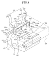
- Figure 4 is a perspective view of a laser beam isolation apparatus according to the present invention; and
- Figure 5A and 5B are partial sectional views illustrating an operation of the laser beam isolation apparatus of Figure 4.
-
- Referring to Figure 5A, a laser printer, having a laser
beam isolation apparatus 100 according to the present invention, includes ahousing 114 having acover 120 movably secured to ahinge axis 120a so as to be pivoted thereon, adeveloper unit 106, mounted in thehousing 114 and including aphotoconductive drum 103 on which images are formed by using an electrical property thereof, and alaser scanning unit 104 to scan alaser beam 111 across the surface of thephotoconductive drum 103. - The LSU 104 includes a laser diode (not shown) mounted in a
housing 114 to emit thelaser beam 111, a rotary polygonal mirror (not shown) to scan thelaser beam 111 at a constant linear velocity, a scan lens (not shown) to compensate for the error in thelaser beam 111 reflected from the rotary polygonal mirror, a mirror (not shown) to reflect thelaser beam 111 onto the surface of thephotoconductive drum 103 via apassing hole 104f, and ahousing 101 having apassing hole 104e formed therein through which thelaser beam 111 reflected from the mirror passes. - Referring to Figure 4, and additionally to Figure 5A and 5B, the laser
beam isolation apparatus 100 includes ablocking portion 152 formed on the LSU 104 so as to be moveable between a blocking position (Figure 5B) where it blocks thepassing hole 104e of the LSU 104 and an non-blocking position (Figure 5A) in which thepassing hole 104e is open, aguide portion 160 mounted on the LSU 104 relative to theblocking portion 152 for guiding theblocking portion 152 between the blocking and non-blocking positions, and operatingportions 155 on thedeveloper unit 106 which holds the blockingportion 152 at an upper position along theguide portion 160. - The blocking
portion 152 includes an elongate passinghole blocking plate 153 shaped to completely cover thepassing hole 104e of the LSU 104, and first andsecond fingers hole blocking plate 153 through first and second passing holes 102 (the second passing hole is hidden in Figure 5A and 5B) towards thedeveloper unit 106. - The
passing hole 104e is tapered and can be easily sealed by the elongated passinghole blocking plate 153. Asealing plug 153a is formed on the bottom of the blockingplate 153 and is shaped so as to complement thepassing hole 104e, i.e. to be correspondingly tapered so that it can be inserted with a good fit into thepassing hole 104e, thus sealing thepassing hole 104e when the elongate passinghole blocking plate 153 is placed over thepassing hole 104e. - The first and the
second fingers curved faces 154a', 154b' at their lower ends so as minimize friction between thefingers second operating projections fingers second operating projections - The
guide portion 160 includes first and second pairs ofinclined bearing surfaces 167, 168 (Figure 4) formed on the elongate passinghole blocking plate 153 at a proper interval, and first and secondinclined guide units inclined passages inclined bearing surfaces passages hole blocking plate 153 is guided such that it moves along a slope having a predetermined steepness. - The first pair of inclined
bearing surfaces 167 includes first and secondinclined bearing surfaces hole blocking plate 153 towards thefirst finger 154a. The second pair of inclinedbearing surfaces 168 includes third and fourth inclinedbearing surfaces hole blocking plate 153 towards thesecond finger 154b. - The first
inclined guide unit 162 includes first andsecond guide members inclined passage 166a that guides the first and secondinclined bearing surfaces inclined guide unit 164 includes third andfourth guide members inclined passage 166b that guides the third and fourth inclined bearingsurfaces - Accordingly, in accordance with the ascending and descending of the elongated passing
hole blocking plate 153, the first and secondinclined bearing surfaces second guide members inclined bearing sufaces fourth guide plates - The first and the second
slider guide units third guide members fourth guide plates hole blocking plate 153 from the first and secondinclined passages third guide members fourth guide members inclined bearing surfaces hole blocking plate 153 can be easily inserted in theinclined passages 166a,b during assembly. - The
operating portions 155 include the first andsecond operating projections developer unit 106 in correspondence with the first and thesecond fingers developer unit 106, push the elongate passinghole blocking plate 153 of the blockingportion 152 upwards along the first and thesecond passages hole blocking plate 153 in the non-blocking position. For smooth contact with the first and secondcurved faces 154a', 154b' at the lower ends of the first andsecond fingers second operating projections curved faces 155a', 155b'. - Accordingly, upon the mounting of the
developer unit 106, theoperating portions 155 push the first andsecond fingers hole blocking plate 153 to the non-blocking position, while with thecover 120 open and thedeveloper unit 106 removed, the force upwardly pushing the first and thesecond fingers hole blocking plate 153 to move to the blocking position to block thepassing hole 104e of the LSU 104. - The operation of the laser
beam isolation apparatus 100 described above will now be described below with reference to Figures 4 and additionally to Figure 5A and 5B. - First, as shown in Figure 5B, with the
cover 120 of the laser printer open and thedeveloper unit 106 removed for purposes such as repair or replacement of thedeveloper unit 106, the elongate passinghole blocking plate 153 of theblocking portion 152 has dropped from the non-blocking position under its own weight. - In this situation, the first and the second
inclined guide surfaces inclined guide surfaces 167 are guided obliquely downwards by the first and second inclined guide faces 163a, 163b of the first andsecond guide members inclined bearing surfaces inclined bearing surfaces 168 are guided obliquely downwards by the third and fourth inclined guide faces 165a, 165b of the third and thefourth guide members - As the elongated passing
hole blocking plate 153 is moved downward to the proximity of the passinghole 104e by its own weight, the sealingplug 153a is inserted in the passinghole 104e to thereby seal the same. Since the passinghole 104e is formed to have an tapering section, it is easily sealed by the sealingplug 153a which has a complementary section. - Accordingly, when the
cover 120 is opened and thedeveloper unit 106 removed, or when thecover 120 is opened with thedeveloper unit 106 having already been removed, thelaser beam 111, which may possibly be emitted from the laser diode due to a fault in the laser beam blocking switch, does not escape to the outside of theLSU 104 but is instead contained within theLSU 104 due to the sealingplug 153a that seals the passinghole 104e. - Furthermore, since the sealing
plug 153a seals the passinghole 104e as the elongated passinghole blocking plate 153 is moved downward by its own weight, entrance of foreign substances such as dust into theLSU 104 through the passinghole 104e is prevented. - The first and
second operating projections portions 155 formed on the top of thedeveloper unit 106 raise the first andsecond fingers developer unit 106. Accordingly, the elongated passinghole blocking plate 153 of the blockingportion 152, which was moved down to the blocking position by its own weight, moves upwards. - The first and second inclined bearing
surfaces guide portions 160 are moved upward while being guided along the first and the secondinclined passages fourth guide members - As the elongated passing
hole blocking plate 153 moves upwards to the opening position that completely opens the passinghole 104e, as shown in Figure 5A, thelaser beam 111 from the laser diode of theLSU 104 can irradiate on the surface of thephotoconductive drum 103 through the passinghole 104e. - Then as the
developer unit 106 is mounted, positioning the elongated passinghole blocking plate 153 in the full opened position, repair or replacement of thedeveloper unit 106 is completed by closing thecover 120. - As described above, with the laser beam isolation apparatus according to the embodiment of the present invention, when either opening the cover and removing the developer unit, or opening the cover with the developer unit having already been removed, a laser beam from the laser diode is prevented from being emitted to the outside even when the laser diode operates due to abnormal operation of the laser beam blocking switch. Also, entrance of foreign substances into the LSU through the passing hole can be prevented.
- Furthermore, since the blocking portion of the laser beam isolation apparatus according to the embodiment of the present invention is moved to the blocking position by its own weight, there is no requirement for separate parts such as elastic springs. As a result, manufacturing costs are reduced, while the structure of the apparatus is simplified.
Claims (26)
- A laser printing apparatus including a removable developer unit (106), including a photosensitive drum (103), and a laser scanning unit (104), including a laser, an aperture (104e) for allowing a laser beam from the laser to pass out of the laser scanning unit (104) into the developer unit (106) and blocking means (152) for blocking the aperture (104e), the developer unit (106) having a structure (155) for displacing the blocking means (152) so as to unblock said aperture (104e) when mounted in the printing apparatus, characterised in that the blocking means (152) is configured such that, when the developer unit (106) is removed from the printing apparatus, gravity causes the blocking means (152) to block said aperture (104e).
- A laser printing apparatus according to claim 1, wherein the aperture (104e) opens substantially downwards.
- A laser printing apparatus according to claim 2, wherein the blocking means (152) is constrained to move along an inclined path (166a, 166b) between blocking and non-blocking positions.
- A laser printing apparatus according to claim 3, wherein said structure comprises a cam (155a) and the blocking means (152) includes a downwardly directed cam follower (154a), the cam and cam follower being configured such that the blocking means (152) is driven upwards along said path (166a, 166b) by installation of the developer unit (106) in the apparatus.
- A laser printing apparatus according to claim 4, wherein the aperture (104e) is a slot and the blocking means (152) comprises an elongate element (153) configured for blocking the aperture (104e).
- A laser printing apparatus according to claim 5, wherein said cam follower (154a) comprises a finger depending from one end of the elongate element (153), a further cam follower (154b), comprising a finger, depends from the other end of the elongate member (153), the developer unit includes a further cam (155b) for cooperation with the further cam follower (154b).
- A laser printing apparatus according to claim 6, wherein the cams (155a, 155b) comprise first and second humps on the developer unit.
- A laser beam isolation apparatus of a laser printer having a housing having a cover, a developer unit mounted in the housing and having a photoreceptor body to form an image by using an electric property of a surface thereof, a laser scanning unit mounted in the housing and comprising a light source to irradiate a laser beam onto the photoreceptor, and a passing hole through which the laser beam is emitted from the light source toward the surface of the photoreceptor body, comprising:a blocking portion formed on the laser scanning unit to be moved between a blocking position and an opening position, the blocking position to block the passing hole and the opening position to open the passing hole; andan operating portion formed on the developer unit, and operated to move the blocking portion in a first direction.
- The laser beam isolation apparatus of claim 8, further comprising
a guide portion mounted in the laser scanning unit to guide the blocking portion to move between the blocking position and the opening position. - The laser beam isolation apparatus of claim 9, wherein the blocking portion comprises:an elongated passing hole blocking plate to completely seal the passing hole of the laser scanning unit when the blocking portion is in the blocking position; anda projection lever protruding from the elongated passing hole blocking plate.
- The laser beam isolation apparatus of claim 10, wherein the guide portion comprises:an inclined slider formed on the elongated passing hole blocking plate; andan inclined slider guide having an inclined passage to receive the inclined slider therein and guide the elongated passing hole blocking plate to move along a predetermined slope thereof.
- The laser beam isolation apparatus of claim 11, wherein the inclined slider guide comprises a stopper to limit a movement of the elongated passing hole blocking plate within a predetermined range thereby preventing a deviation of the elongated passing hole blocking plate from the inclined passage.
- The laser beam isolation apparatus of claim 11, wherein the operating portion comprises an operating projection formed on the developer unit to correspond to the projection lever to push the projection lever opposite to the first direction and thus move the blocking portion to the opening position upon mounting the developer unit.
- The laser beam isolation apparatus of claim 13, wherein the projection lever and the operating projection include a rounded contact surface for smooth contact between the projection lever and the operating projection.
- An apparatus comprising:a scan unit to emit a laser, including a blocking portion to selectively block the laser; anda developing unit to develop an image from the emitted laser and including a moving portion to selectively move the blocking portion to block the laser.
- The apparatus of claim 15, wherein the laser is selectively blocked to contain the laser within the scan unit.
- The apparatus of claim 16, wherein the scan unit defines a hole therein, and the blocking portion is selectively moved between a first position to block the laser, and a second position to allow the laser to pass through the hole.
- The apparatus of claim 17, wherein the developing unit is selectively removable, and the blocking portion blocks the laser when the developing unit is removed.
- The apparatus of claim 18, wherein the blocking portion comprises:a plate to block the hole; anda projection lever extending from the plate.
- The apparatus of claim 19, wherein the hole has a frusto-conical shape, and the blocking portion comprises a sealing projection having a frusto-conical shape to be inserted into the hole.
- The apparatus of claim 20, further comprising a guide mounted in the scan unit to guide the blocking portion between the first and second positions.
- The apparatus of claim 21, wherein the guide comprises:a slider formed on the plate; anda slider guide to receive and guide the slider.
- The apparatus of claim 22, wherein the moving portion comprises a projection extending from the developing unit.
- The apparatus of claim 23, wherein the projection corresponds to the projection lever to thereby push the blocking portion along the slider to the second position when the developing unit is installed.
- The apparatus of claim 24, wherein the blocking portion moves to the first position by its own weight when the developing unit is removed.
- An apparatus comprising:wherein the developing unit is removable and the blocking portion moves to a position to block the laser by its own weight when the developing unit is removed.a scan unit to emit a laser, including a blocking portion to selectively block the laser; and a developing unit to develop an image from the emitted laser,
Applications Claiming Priority (2)
| Application Number | Priority Date | Filing Date | Title |
|---|---|---|---|
| KR2002040601 | 2002-07-12 | ||
| KR10-2002-0040601A KR100449088B1 (en) | 2002-07-12 | 2002-07-12 | laser beam isolation apparatus and image forming apparatus having the same |
Publications (3)
| Publication Number | Publication Date |
|---|---|
| EP1380431A1 true EP1380431A1 (en) | 2004-01-14 |
| EP1380431B1 EP1380431B1 (en) | 2005-04-20 |
| EP1380431B8 EP1380431B8 (en) | 2005-06-15 |
Family
ID=29728791
Family Applications (1)
| Application Number | Title | Priority Date | Filing Date |
|---|---|---|---|
| EP03253147A Expired - Lifetime EP1380431B8 (en) | 2002-07-12 | 2003-05-20 | Laserblocking device for a laser printing apparatus |
Country Status (5)
| Country | Link |
|---|---|
| US (1) | US7002615B2 (en) |
| EP (1) | EP1380431B8 (en) |
| KR (1) | KR100449088B1 (en) |
| CN (1) | CN100410817C (en) |
| DE (1) | DE60300528T2 (en) |
Families Citing this family (9)
| Publication number | Priority date | Publication date | Assignee | Title |
|---|---|---|---|---|
| KR100657282B1 (en) * | 2004-10-29 | 2006-12-14 | 삼성전자주식회사 | Developer and electrophotographic image forming apparatus having the same |
| US7212221B2 (en) * | 2004-11-17 | 2007-05-01 | Xerox Corporation | ROS shutter system |
| KR100611307B1 (en) * | 2005-06-20 | 2006-08-10 | 삼성전자주식회사 | Development unit and image forming apparatus |
| KR100609905B1 (en) * | 2005-06-30 | 2006-08-08 | 삼성전자주식회사 | Image forming apparatus and optical scanning device |
| KR20070087742A (en) * | 2005-09-30 | 2007-08-29 | 삼성전자주식회사 | An image forming apparatus having a scanning light shielding member |
| JP5440160B2 (en) * | 2009-12-25 | 2014-03-12 | セイコーエプソン株式会社 | Loading device, conveying device, and recording device |
| EP3223078B1 (en) * | 2011-08-19 | 2021-09-29 | Hewlett-Packard Development Company, L.P. | Printer with toner container |
| KR101361205B1 (en) * | 2011-12-20 | 2014-03-12 | 삼성디스플레이 주식회사 | Laser processing apparatus |
| US11048205B1 (en) * | 2020-02-10 | 2021-06-29 | Datamax-O'neil Corporation | Safety mechanism for printing apparatus |
Citations (4)
| Publication number | Priority date | Publication date | Assignee | Title |
|---|---|---|---|---|
| JPH032775A (en) * | 1989-05-30 | 1991-01-09 | Tokyo Electric Co Ltd | Shutter device for laser beam printer |
| US5157416A (en) * | 1990-07-26 | 1992-10-20 | Brother Kogyo Kabushiki Kaisha | Laser scanner protecting mechanism |
| JPH06332083A (en) * | 1993-05-21 | 1994-12-02 | Noritsu Koki Co Ltd | Opening and closing structure of shutter in photo printing machine |
| US20010021295A1 (en) * | 2000-03-09 | 2001-09-13 | Kazuki Yoshida | Laser light interrupting device |
Family Cites Families (7)
| Publication number | Priority date | Publication date | Assignee | Title |
|---|---|---|---|---|
| JPH0657462B2 (en) * | 1986-07-16 | 1994-08-03 | 東京電気株式会社 | Electrophotographic device |
| JPH01276164A (en) * | 1988-04-28 | 1989-11-06 | Topcon Corp | Optical unit with laser light source |
| JPH04107570A (en) * | 1990-08-29 | 1992-04-09 | Minolta Camera Co Ltd | Laser printer |
| JPH0519603A (en) * | 1991-07-17 | 1993-01-29 | Canon Inc | Laser scanning device |
| JP2587956Y2 (en) * | 1992-03-24 | 1998-12-24 | 旭光学工業株式会社 | Light beam shielding structure of optical scanning device |
| KR950024557U (en) * | 1994-02-21 | 1995-09-13 | 송명석 | Roller skate with reverse rotation prevention device |
| KR100395522B1 (en) * | 2000-08-25 | 2003-08-25 | 삼성전자주식회사 | Laser printer |
-
2002
- 2002-07-12 KR KR10-2002-0040601A patent/KR100449088B1/en not_active Expired - Fee Related
-
2003
- 2003-05-07 US US10/430,256 patent/US7002615B2/en not_active Expired - Lifetime
- 2003-05-20 DE DE60300528T patent/DE60300528T2/en not_active Expired - Lifetime
- 2003-05-20 EP EP03253147A patent/EP1380431B8/en not_active Expired - Lifetime
- 2003-07-08 CN CNB031471811A patent/CN100410817C/en not_active Expired - Fee Related
Patent Citations (4)
| Publication number | Priority date | Publication date | Assignee | Title |
|---|---|---|---|---|
| JPH032775A (en) * | 1989-05-30 | 1991-01-09 | Tokyo Electric Co Ltd | Shutter device for laser beam printer |
| US5157416A (en) * | 1990-07-26 | 1992-10-20 | Brother Kogyo Kabushiki Kaisha | Laser scanner protecting mechanism |
| JPH06332083A (en) * | 1993-05-21 | 1994-12-02 | Noritsu Koki Co Ltd | Opening and closing structure of shutter in photo printing machine |
| US20010021295A1 (en) * | 2000-03-09 | 2001-09-13 | Kazuki Yoshida | Laser light interrupting device |
Non-Patent Citations (2)
| Title |
|---|
| PATENT ABSTRACTS OF JAPAN vol. 015, no. 111 (P - 1180) 18 March 1991 (1991-03-18) * |
| PATENT ABSTRACTS OF JAPAN vol. 1995, no. 03 28 April 1995 (1995-04-28) * |
Also Published As
| Publication number | Publication date |
|---|---|
| EP1380431B8 (en) | 2005-06-15 |
| DE60300528D1 (en) | 2005-05-25 |
| US20040008246A1 (en) | 2004-01-15 |
| DE60300528T2 (en) | 2006-03-09 |
| EP1380431B1 (en) | 2005-04-20 |
| US7002615B2 (en) | 2006-02-21 |
| CN1472606A (en) | 2004-02-04 |
| CN100410817C (en) | 2008-08-13 |
| KR100449088B1 (en) | 2004-09-18 |
| KR20040006350A (en) | 2004-01-24 |
Similar Documents
| Publication | Publication Date | Title |
|---|---|---|
| US7133626B2 (en) | Image forming apparatus | |
| CN113805451B (en) | Image forming apparatus | |
| US8768208B2 (en) | Image forming apparatus with cartridge supporting member and preventing members for ensuring mounting of cartridges in associated mounting portions | |
| EP1650776A1 (en) | Open/close switch mechanism having simple configuration | |
| JP4723004B2 (en) | Optical scanning device and image forming apparatus having the same | |
| EP1380431B1 (en) | Laserblocking device for a laser printing apparatus | |
| US10845751B2 (en) | Image forming apparatus including optical print head | |
| US7187886B2 (en) | Image forming apparatus having a securing member to secure an image forming unit to a housing body | |
| US10353337B2 (en) | Image forming apparatus including optical print head | |
| US9618876B2 (en) | Image forming apparatus | |
| US5153607A (en) | Laser shutter mechanism | |
| KR100767110B1 (en) | Laser beam blocking device and image forming device having the same | |
| US9733611B2 (en) | Image forming apparatus | |
| KR20060006648A (en) | Image Forming Device | |
| JPH03100571A (en) | Image forming device | |
| JP2007144853A (en) | Optical scanning apparatus and image forming apparatus | |
| JPH01185669A (en) | image recording device | |
| JPH09185310A (en) | Electrophotographic device | |
| JPH0535055A (en) | Image forming device | |
| JP2006071920A (en) | Image forming apparatus | |
| JP2004038110A (en) | Scanning optical device and image forming apparatus |
Legal Events
| Date | Code | Title | Description |
|---|---|---|---|
| PUAI | Public reference made under article 153(3) epc to a published international application that has entered the european phase |
Free format text: ORIGINAL CODE: 0009012 |
|
| AK | Designated contracting states |
Kind code of ref document: A1 Designated state(s): AT BE BG CH CY CZ DE DK EE ES FI FR GB GR HU IE IT LI LU MC NL PT RO SE SI SK TR |
|
| AX | Request for extension of the european patent |
Extension state: AL LT LV MK |
|
| 17P | Request for examination filed |
Effective date: 20040213 |
|
| 17Q | First examination report despatched |
Effective date: 20040408 |
|
| GRAP | Despatch of communication of intention to grant a patent |
Free format text: ORIGINAL CODE: EPIDOSNIGR1 |
|
| AKX | Designation fees paid |
Designated state(s): DE FR GB NL |
|
| RAP1 | Party data changed (applicant data changed or rights of an application transferred) |
Owner name: SAMSUNG ELECTRONICS CO., LTD. |
|
| GRAS | Grant fee paid |
Free format text: ORIGINAL CODE: EPIDOSNIGR3 |
|
| GRAA | (expected) grant |
Free format text: ORIGINAL CODE: 0009210 |
|
| RBV | Designated contracting states (corrected) |
Designated state(s): DE FR GB |
|
| AK | Designated contracting states |
Kind code of ref document: B1 Designated state(s): DE FR GB |
|
| REG | Reference to a national code |
Ref country code: GB Ref legal event code: FG4D |
|
| REG | Reference to a national code |
Ref country code: IE Ref legal event code: FG4D |
|
| REF | Corresponds to: |
Ref document number: 60300528 Country of ref document: DE Date of ref document: 20050525 Kind code of ref document: P |
|
| RBV | Designated contracting states (corrected) |
Designated state(s): DE FR GB NL |
|
| PLBE | No opposition filed within time limit |
Free format text: ORIGINAL CODE: 0009261 |
|
| STAA | Information on the status of an ep patent application or granted ep patent |
Free format text: STATUS: NO OPPOSITION FILED WITHIN TIME LIMIT |
|
| ET | Fr: translation filed | ||
| 26N | No opposition filed |
Effective date: 20060123 |
|
| REG | Reference to a national code |
Ref country code: FR Ref legal event code: PLFP Year of fee payment: 14 |
|
| REG | Reference to a national code |
Ref country code: NL Ref legal event code: PD Owner name: S-PRINTING SOLUTION CO., LTD.; KO Free format text: DETAILS ASSIGNMENT: CHANGE OF OWNER(S), ASSIGNMENT; FORMER OWNER NAME: SAMSUNG ELECTRONICS CO., LTD. Effective date: 20170221 |
|
| REG | Reference to a national code |
Ref country code: GB Ref legal event code: 732E Free format text: REGISTERED BETWEEN 20170406 AND 20170412 |
|
| REG | Reference to a national code |
Ref country code: FR Ref legal event code: PLFP Year of fee payment: 15 |
|
| REG | Reference to a national code |
Ref country code: DE Ref legal event code: R082 Ref document number: 60300528 Country of ref document: DE Representative=s name: HOEFER & PARTNER PATENTANWAELTE MBB, DE Ref country code: DE Ref legal event code: R082 Ref document number: 60300528 Country of ref document: DE Ref country code: DE Ref legal event code: R081 Ref document number: 60300528 Country of ref document: DE Owner name: HP PRINTING KOREA CO., LTD., SUWON-SI, KR Free format text: FORMER OWNER: SAMSUNG ELECTRONICS CO., LTD., SUWON-SI, GYEONGGI-DO, KR Ref country code: DE Ref legal event code: R081 Ref document number: 60300528 Country of ref document: DE Owner name: HEWLETT-PACKARD DEVELOPMENT COMPANY, L.P., SPR, US Free format text: FORMER OWNER: SAMSUNG ELECTRONICS CO., LTD., SUWON-SI, GYEONGGI-DO, KR Ref country code: DE Ref legal event code: R081 Ref document number: 60300528 Country of ref document: DE Owner name: S-PRINTING SOLUTION CO., LTD., SUWON-SI, KR Free format text: FORMER OWNER: SAMSUNG ELECTRONICS CO., LTD., SUWON-SI, GYEONGGI-DO, KR |
|
| REG | Reference to a national code |
Ref country code: FR Ref legal event code: TP Owner name: S-PRINTING SOLUTION CO., LTD., KR Effective date: 20170912 |
|
| REG | Reference to a national code |
Ref country code: FR Ref legal event code: PLFP Year of fee payment: 16 |
|
| REG | Reference to a national code |
Ref country code: NL Ref legal event code: HC Owner name: HP PRINTING KOREA CO., LTD.; KR Free format text: DETAILS ASSIGNMENT: CHANGE OF OWNER(S), CHANGE OF OWNER(S) NAME; FORMER OWNER NAME: S-PRINTING SOLUTION CO., LTD. Effective date: 20180816 |
|
| REG | Reference to a national code |
Ref country code: DE Ref legal event code: R082 Ref document number: 60300528 Country of ref document: DE Ref country code: DE Ref legal event code: R081 Ref document number: 60300528 Country of ref document: DE Owner name: HP PRINTING KOREA CO., LTD., SUWON-SI, KR Free format text: FORMER OWNER: S-PRINTING SOLUTION CO., LTD., SUWON-SI, GYEONGGI-DO, KR Ref country code: DE Ref legal event code: R081 Ref document number: 60300528 Country of ref document: DE Owner name: HEWLETT-PACKARD DEVELOPMENT COMPANY, L.P., SPR, US Free format text: FORMER OWNER: S-PRINTING SOLUTION CO., LTD., SUWON-SI, GYEONGGI-DO, KR |
|
| REG | Reference to a national code |
Ref country code: NL Ref legal event code: PD Owner name: HEWLETT-PACKARD DEVELOPMENT COMPANY, L.P.; US Free format text: DETAILS ASSIGNMENT: CHANGE OF OWNER(S), CHANGE OF LEGAL ENTITY; FORMER OWNER NAME: SAMSUNG ELECTRONICS CO., LTD. Effective date: 20191030 |
|
| REG | Reference to a national code |
Ref country code: DE Ref legal event code: R081 Ref document number: 60300528 Country of ref document: DE Owner name: HEWLETT-PACKARD DEVELOPMENT COMPANY, L.P., SPR, US Free format text: FORMER OWNER: HP PRINTING KOREA CO., LTD., SUWON-SI, GYEONGGI-DO, KR |
|
| REG | Reference to a national code |
Ref country code: GB Ref legal event code: 732E Free format text: REGISTERED BETWEEN 20191212 AND 20191218 |
|
| PGFP | Annual fee paid to national office [announced via postgrant information from national office to epo] |
Ref country code: DE Payment date: 20200421 Year of fee payment: 18 Ref country code: FR Payment date: 20200422 Year of fee payment: 18 Ref country code: NL Payment date: 20200424 Year of fee payment: 18 |
|
| PGFP | Annual fee paid to national office [announced via postgrant information from national office to epo] |
Ref country code: GB Payment date: 20200423 Year of fee payment: 18 |
|
| REG | Reference to a national code |
Ref country code: DE Ref legal event code: R119 Ref document number: 60300528 Country of ref document: DE |
|
| REG | Reference to a national code |
Ref country code: NL Ref legal event code: MM Effective date: 20210601 |
|
| GBPC | Gb: european patent ceased through non-payment of renewal fee |
Effective date: 20210520 |
|
| PG25 | Lapsed in a contracting state [announced via postgrant information from national office to epo] |
Ref country code: GB Free format text: LAPSE BECAUSE OF NON-PAYMENT OF DUE FEES Effective date: 20210520 Ref country code: DE Free format text: LAPSE BECAUSE OF NON-PAYMENT OF DUE FEES Effective date: 20211201 |
|
| PG25 | Lapsed in a contracting state [announced via postgrant information from national office to epo] |
Ref country code: NL Free format text: LAPSE BECAUSE OF NON-PAYMENT OF DUE FEES Effective date: 20210601 Ref country code: FR Free format text: LAPSE BECAUSE OF NON-PAYMENT OF DUE FEES Effective date: 20210531 |