EP1378998A1 - Method of operating a microcontroller chip having an internal RC oscillator, and microcontroller chip embodying the method - Google Patents
Method of operating a microcontroller chip having an internal RC oscillator, and microcontroller chip embodying the method Download PDFInfo
- Publication number
- EP1378998A1 EP1378998A1 EP02291700A EP02291700A EP1378998A1 EP 1378998 A1 EP1378998 A1 EP 1378998A1 EP 02291700 A EP02291700 A EP 02291700A EP 02291700 A EP02291700 A EP 02291700A EP 1378998 A1 EP1378998 A1 EP 1378998A1
- Authority
- EP
- European Patent Office
- Prior art keywords
- calibration
- frequency
- ratio
- oscillator
- counter
- Prior art date
- Legal status (The legal status is an assumption and is not a legal conclusion. Google has not performed a legal analysis and makes no representation as to the accuracy of the status listed.)
- Granted
Links
- 238000000034 method Methods 0.000 title claims abstract description 28
- 230000002093 peripheral effect Effects 0.000 claims abstract description 20
- 230000015654 memory Effects 0.000 claims abstract description 13
- 238000012545 processing Methods 0.000 claims description 17
- 238000001914 filtration Methods 0.000 claims description 10
- 238000005070 sampling Methods 0.000 claims description 7
- 230000010355 oscillation Effects 0.000 claims description 6
- 238000004891 communication Methods 0.000 claims description 5
- 230000006870 function Effects 0.000 claims 4
- 238000012360 testing method Methods 0.000 description 5
- 238000010586 diagram Methods 0.000 description 4
- 238000013461 design Methods 0.000 description 3
- 238000004519 manufacturing process Methods 0.000 description 3
- 230000001419 dependent effect Effects 0.000 description 2
- 238000005516 engineering process Methods 0.000 description 2
- 238000009825 accumulation Methods 0.000 description 1
- 230000004913 activation Effects 0.000 description 1
- 238000012937 correction Methods 0.000 description 1
- 238000012986 modification Methods 0.000 description 1
- 230000004048 modification Effects 0.000 description 1
- 230000000630 rising effect Effects 0.000 description 1
Images


Classifications
-
- H—ELECTRICITY
- H03—ELECTRONIC CIRCUITRY
- H03L—AUTOMATIC CONTROL, STARTING, SYNCHRONISATION OR STABILISATION OF GENERATORS OF ELECTRONIC OSCILLATIONS OR PULSES
- H03L1/00—Stabilisation of generator output against variations of physical values, e.g. power supply
Definitions
- the present invention relates to the clocking of microcontroller circuits. It applies to microcontroller chips having an internal RC oscillator to define the operating frequency of the central processing unit (CPU).
- CPU central processing unit
- General purpose microcontrollers are operated with various kinds of clock sources.
- the cheapest method is to use an internal RC oscillator. This method is very interesting for the application developers, particularly for mass usage applications with a relatively low clock frequency, e.g. 2-5 MHz.
- the frequency delivered by a RC oscillator source is very dependent on the operating conditions, particularly on temperature.
- the frequency variation range depends on the circuit design and its manufacturing process. It may be up to about ⁇ 40 %.
- the available solutions to adjust the internal RC oscillator are based on the internal chip design.
- the frequency adjustment is performed by means of a array of resistors and switches forming a digital potentiometer.
- a calibration value stored in a specific register determines which resistors are to be included in the resistive part of the RC circuit and controls the states of the switches accordingly.
- the calibration value is determined beforehand by means of an external frequency reference.
- the microcontroller has specific EEPROM registers capable of storing a calibration value. Such registers are not available in certain technologies, such as in ROM or flash memory microcontrollers.
- An object of the present invention is to propose a cheap and efficient method for clocking a microcontroller chip from an internal RC oscillator.
- the invention thus proposes a method of operating a microcontroller chip having a CPU, memory means for storing programs and data, at least one peripheral unit for interacting with the outside of the chip, and an internal RC oscillator for providing clock signals to the central processing and peripheral units.
- the at least one peripheral unit comprises a timer unit having a counter incremented at a frequency proportional to an oscillation frequency of the RC oscillator
- the method comprises the steps of:
- the internal RC oscillator of the chip is not forced to oscillate at a specified frequency.
- the parameter variations due to the manufacturing process, the operating temperature, etc. are tolerated. Their compensation is not made by means of a hardware modification of the oscillator parameters, but by means of the software run in the CPU of the microcontroller.
- the software corrects corresponding parameters based on the evaluated calibration ratio in order to meet the requirement.
- a calibration phase is typically used when the apparatus incorporating the microcontroller chip is switched on. Depending on the application and its environment, it may be necessary to update the calibration ratio from time to time when the apparatus remains under voltage.
- microcontroller chip comprising:
- the stored programs include instructions for processing the sampled values of the counter to derive a calibration ratio, and instructions for performing software correction of at least one parameter based on the calibration ratio to compensate for frequency variations of the RC oscillator.
- Figure 1 illustrates the general architecture of a microcontroller circuit 10.
- the indicated bus 11 is understood to include all the lines (data, address, control, clock, power supply, ...) used to distribute the data and signals among the various units of the microcontroller.
- the CPU 12 is conventionally associated with a program memory 13 and with a random access memory (RAM) 14.
- RAM random access memory
- the clock signals used within the microcontroller circuit 10 are provided by a time base 15 which derives them from an internal RC oscillator 17.
- the oscillation frequency of the RC circuit 17 is not adjusted to match a specific reference value.
- the RC oscillator frequency drifts so that F CPU will normally differ from its target value.
- time base 15 of the microcontroller may also receive external clock signals from an input pin of the chip.
- the present invention applies to an operating mode in which the basic frequency is provided by the RC oscillator 17.
- the microcontroller chip 10 further includes a number of peripheral units which, in the example shown in figure 1 consists of a 16-bit timer unit 18 and a serial communication interface (SCI) unit 19.
- peripheral units which, in the example shown in figure 1 consists of a 16-bit timer unit 18 and a serial communication interface (SCI) unit 19.
- SCI serial communication interface
- the 16-bit timer unit 18 includes a free running 16-bit counter incremented at a frequency proportional to the oscillation frequency of the RC oscillator 17. This incrementation frequency may be selected as half of the CPU clock frequency F CPU As indicated in the lower diagram of figure 2, the overflow value of the 16-bit counter is for example FFFC in hexadecimal notation.
- the 16-bit timer unit 18 has a capture input 20. When an active (falling) edge occurs in a signal supplied at the capture input 20, the timer unit 18 generates an interrupt for the CPU 12 and presents the counter value on the data bus. The interrupt program samples the current counter value and stores it in RAM 14.
- the calibration source 21 then consists of a simple voltage limiter circuit to convert the mains voltage into a substantially square calibration signal S having a low voltage, e.g. 0-5 V. This limiter circuit may be associated with a band-pass filter to remove high frequency components which may be superimposed on the nominal mains frequency.
- each falling edge of the calibration signal S gives rise to the capture of the counter value, as illustrated in figure 2.
- Figure 3 illustrate a possible calibration procedure which may be carried out by means of a short piece of software stored in program memory 14.
- step 31 The capture process if first initialized in step 30, which includes activation the calibration source 21.
- step 31 it is determined whether an overflow of the 16-bit timer has occurred between the two captures (test 32). Indeed, the relevant difference value to be compared with a reference value depending on the reference frequency F R is dependent on whether one or more counter overflows took place in the meantime. If there has been no intervening overflow (such as between captures #1 and #2 in figure 2), the relevant difference value CC is simply C i+1 - C i (step 33).
- step 34 If there has been an overflow (such as between captures #2 and #3 in figure 2), the difference value CC is equal to 0xFFFF-C i + C i+1 (step 34).
- the typical frequency range of the RC oscillator is normally such that 0 or 1 overflow occurs between two consecutive captures. If necessary, the formulas of step 33 and 34 are readily adapted to cases where more than one overflow would be possible.
- the last step 35 of the calibration procedure shown in figure 3 consists in computing the calibration ratio CR by dividing the difference value CC by a pre-calculated reference value CC REF .
- step 35 Once the calibration ratio CR is computed in step 35, it is stored in RAM 14 for subsequent use by the application software to perform correction of one or more timing parameters.
- Figure 4 illustrates an alternative embodiment of the calibration procedure, which advantageously uses a low-pass filtering of successive difference values CC.
- Such filtering eliminates glitches or spikes which may remain in the calibration signal S in spite of the band-pass filtering performed in the external calibration source 21.
- step 40 of the procedure of figure 4 the captures are initialized as in step 30 of figure 3, and the variables i and MCC used in the low-pass filtering are also initialized to 0.
- a loop is then performed to compute an average of a predetermined number K of difference values CC falling within a capture range.
- each iteration in this loop begins with steps 31-34 identical to those of figure 3.
- a capture range is determined in step 46 for filtering out possible glitches of signal S in the following iterations.
- the capture range is for example determined as being ⁇ 10 % of the first calculated difference value CC.
- the difference value CC obtained in step 33 is examined to determine whether it falls within the capture range (test 47). If the current CC value is out of the capture range, the procedure is reinitialized in step 40. Otherwise, the value CC is added to the accumulation variable MCC, and the loop index i is incremented in step 48.
- step 50 the procedure ends in step 50 by computing the calibration ratio as the average difference value MCC/K divided by the reference value CC REF .
- peripheral parameters handled by the programs stored in memory 13 and which may be corrected by the software based on the calibration ratio CR can be of various types.
- a common feature is that such parameter controls the timing of a process without accepting the substantial variations which may be due to the inaccuracy in the RC oscillator frequency.
- the corrected parameters control the frequency and duty ratio of a pulse width modulated (PWM) signal.
- PWM pulse width modulated
- such PWM signal may be generated by means of the 16-bit timer unit 18 having a pulse width modulator mode of operation.
- this timer unit is the same as the one used in the calibration phase. However, it can also be another timer unit of the microcontroller 10.
- the PWM signal shown in figure 5 is produced by comparing the value of the 16-bit free running counter with two thresholds OC1R and OC2R loaded in hexadecimal form by the PWM control program into two registers of the timer unit 18.
- the frequency of the PWM signal is controlled by the OC2R parameter: when the counter value reaches OC2R, a first comparator causes a jump of the counter value to its overflow value 0xFFF and a rising edge of the PWM signal.
- the duty ratio of the PWM signal is controlled by the OC1R parameter: when the counter value reached OC1R, another comparator causes a falling edge of the PWM signal.
- the calibration ratio CR is used by an application program stored in memory 13 to adjust the baud rate of the SCI unit 19.
- the baud rate is usually proportional to the CPU frequency, which can also be adjusted by taking account of the estimated calibration ratio CR.
Landscapes
- Stabilization Of Oscillater, Synchronisation, Frequency Synthesizers (AREA)
Abstract
Description
- The present invention relates to the clocking of microcontroller circuits. It applies to microcontroller chips having an internal RC oscillator to define the operating frequency of the central processing unit (CPU).
- General purpose microcontrollers are operated with various kinds of clock sources. The cheapest method is to use an internal RC oscillator. This method is very interesting for the application developers, particularly for mass usage applications with a relatively low clock frequency, e.g. 2-5 MHz.
- However, the frequency delivered by a RC oscillator source is very dependent on the operating conditions, particularly on temperature. The frequency variation range depends on the circuit design and its manufacturing process. It may be up to about ± 40 %.
- The available solutions to adjust the internal RC oscillator are based on the internal chip design. The frequency adjustment is performed by means of a array of resistors and switches forming a digital potentiometer. A calibration value stored in a specific register determines which resistors are to be included in the resistive part of the RC circuit and controls the states of the switches accordingly. The calibration value is determined beforehand by means of an external frequency reference.
- Such a solution is satisfactory, but the problem is that it is not always possible or desired to implement it.
- It supposes that the microcontroller has specific EEPROM registers capable of storing a calibration value. Such registers are not available in certain technologies, such as in ROM or flash memory microcontrollers.
- Even if the technology is compatible with such a solution, it remains that the array used for adjusting the oscillator frequency occupies a significant surface on the chip and thus increases the hardware cost of the product.
- An object of the present invention is to propose a cheap and efficient method for clocking a microcontroller chip from an internal RC oscillator.
- The invention thus proposes a method of operating a microcontroller chip having a CPU, memory means for storing programs and data, at least one peripheral unit for interacting with the outside of the chip, and an internal RC oscillator for providing clock signals to the central processing and peripheral units. The at least one peripheral unit comprises a timer unit having a counter incremented at a frequency proportional to an oscillation frequency of the RC oscillator According to the invention, the method comprises the steps of:
- connecting an external calibration source to a capture input of the timer unit, the calibration source providing a calibration signal having a predefined reference frequency;
- sampling a value of the counter on active edges of the calibration signal;
- processing the sampled values of the counter to derive a calibration ratio; and
- performing software correction of at least one parameter handled by a program stored in the memory means based on the calibration ratio to compensate for frequency variations of the RC oscillator.
- The internal RC oscillator of the chip is not forced to oscillate at a specified frequency. The parameter variations due to the manufacturing process, the operating temperature, etc. are tolerated. Their compensation is not made by means of a hardware modification of the oscillator parameters, but by means of the software run in the CPU of the microcontroller.
- Where a peripheral unit requires a precise timing, the software corrects corresponding parameters based on the evaluated calibration ratio in order to meet the requirement.
- A calibration phase is typically used when the apparatus incorporating the microcontroller chip is switched on. Depending on the application and its environment, it may be necessary to update the calibration ratio from time to time when the apparatus remains under voltage.
- Another aspect of the invention relates to microcontroller chip comprising:
- a CPU;
- memory means for storing programs and data
- at least one peripheral unit for interacting with the outside of the chip, including a timer unit having a counter incremented at a frequency proportional to an oscillation frequency of the RC oscillator;
- an internal RC oscillator for providing clock signals to the central processing and peripheral units; and
- means for sampling a value of the counter on active edges of a calibration signal having a predefined reference frequency, supplied at a capture input of the timer unit by an external calibration source.
- The stored programs include instructions for processing the sampled values of the counter to derive a calibration ratio, and instructions for performing software correction of at least one parameter based on the calibration ratio to compensate for frequency variations of the RC oscillator.
- Other features and advantages of the invention will become apparent in the following description of non limiting exemplary embodiments, with reference to the accompanying drawings, in which:
- figure 1 is a block diagram of a microcontroller chip according to the present invention;
- figure 2 is a timing diagram illustrating a calibration phase executed in accordance with the invention;
- figures 3 and 4 are flow charts of two possible calibration procedures;
- figure 5 is a timing diagram illustrating an application of the invention to the timing adjustment of a PWM output of the microcontroller.
- Figure 1 illustrates the general architecture of a
microcontroller circuit 10. The indicated bus 11 is understood to include all the lines (data, address, control, clock, power supply, ...) used to distribute the data and signals among the various units of the microcontroller. TheCPU 12 is conventionally associated with aprogram memory 13 and with a random access memory (RAM) 14. - The clock signals used within the
microcontroller circuit 10 are provided by atime base 15 which derives them from aninternal RC oscillator 17. The oscillation frequency of theRC circuit 17 is not adjusted to match a specific reference value. As an example, a target value for the clock frequency FCPU of theCPU 12 may be FCPU = 2 MHz (other values are of course possible, as indicated in the product data sheet). However, due to the inevitable variations in the manufacturing process of the chip and to the environment of the circuit, particularly the temperature, the RC oscillator frequency drifts so that FCPU will normally differ from its target value. - It will be appreciated that the
time base 15 of the microcontroller may also receive external clock signals from an input pin of the chip. In such a case, the present invention applies to an operating mode in which the basic frequency is provided by theRC oscillator 17. - The
microcontroller chip 10 further includes a number of peripheral units which, in the example shown in figure 1 consists of a 16-bit timer unit 18 and a serial communication interface (SCI) unit 19. Of course, other kinds of peripheral units could be provided, depending on the product line of the microcontroller. - The 16-
bit timer unit 18 includes a free running 16-bit counter incremented at a frequency proportional to the oscillation frequency of theRC oscillator 17. This incrementation frequency may be selected as half of the CPU clock frequency FCPU As indicated in the lower diagram of figure 2, the overflow value of the 16-bit counter is for example FFFC in hexadecimal notation. - The 16-
bit timer unit 18 has acapture input 20. When an active (falling) edge occurs in a signal supplied at thecapture input 20, thetimer unit 18 generates an interrupt for theCPU 12 and presents the counter value on the data bus. The interrupt program samples the current counter value and stores it inRAM 14. - In order to calibrate the
RC oscillator 17, anexternal calibration source 21 is connected to thecapture input 20 of the 16-bit timer unit 18. Any kind of calibration source providing a reference frequency FR can be used. It will frequently be convenient to obtain the reference frequency FR of thecalibration source 21 from the mains. Typical reference frequencies are then FR = 50 Hz in Europe and FR = 60 Hz in the United States. Thecalibration source 21 then consists of a simple voltage limiter circuit to convert the mains voltage into a substantially square calibration signal S having a low voltage, e.g. 0-5 V. This limiter circuit may be associated with a band-pass filter to remove high frequency components which may be superimposed on the nominal mains frequency. - In a calibration phase where the
calibration source 21 is activated, each falling edge of the calibration signal S gives rise to the capture of the counter value, as illustrated in figure 2. - Figure 3 illustrate a possible calibration procedure which may be carried out by means of a short piece of software stored in
program memory 14. - The capture process if first initialized in
step 30, which includes activation thecalibration source 21. Once two consecutive counter values ci and ci+1 have been sampled (step 31), it is determined whether an overflow of the 16-bit timer has occurred between the two captures (test 32). Indeed, the relevant difference value to be compared with a reference value depending on the reference frequency FR is dependent on whether one or more counter overflows took place in the meantime. If there has been no intervening overflow (such as betweencaptures # 1 and #2 in figure 2), the relevant difference value CC is simply Ci+1 - Ci (step 33). If there has been an overflow (such as betweencaptures # 2 and #3 in figure 2), the difference value CC is equal to 0xFFFF-Ci+ Ci+1 (step 34). The typical frequency range of the RC oscillator is normally such that 0 or 1 overflow occurs between two consecutive captures. If necessary, the formulas ofstep - The
last step 35 of the calibration procedure shown in figure 3 consists in computing the calibration ratio CR by dividing the difference value CC by a pre-calculated reference value CCREF. The reference value CCREF is inversely proportional to the reference frequency provided by the mains. For a target FCPU of 2 MHz, divided by two to increment the 16-bit counter, it is CCREF = 0x4E20 for the European mains (50 Hz), and CCREF = 0x411B for the US mains (60 Hz). - Once the calibration ratio CR is computed in
step 35, it is stored inRAM 14 for subsequent use by the application software to perform correction of one or more timing parameters. - Figure 4 illustrates an alternative embodiment of the calibration procedure, which advantageously uses a low-pass filtering of successive difference values CC. Such filtering eliminates glitches or spikes which may remain in the calibration signal S in spite of the band-pass filtering performed in the
external calibration source 21. - In
step 40 of the procedure of figure 4, the captures are initialized as instep 30 of figure 3, and the variables i and MCC used in the low-pass filtering are also initialized to 0. A loop is then performed to compute an average of a predetermined number K of difference values CC falling within a capture range. The number K is for instance K = 8. - Each iteration in this loop begins with steps 31-34 identical to those of figure 3. In the first iteration (i = 0 in test 45), a capture range is determined in
step 46 for filtering out possible glitches of signal S in the following iterations. The capture range is for example determined as being ± 10 % of the first calculated difference value CC. In the following iterations (i > 0 in test 45), the difference value CC obtained instep 33 is examined to determine whether it falls within the capture range (test 47). If the current CC value is out of the capture range, the procedure is reinitialized instep 40. Otherwise, the value CC is added to the accumulation variable MCC, and the loop index i is incremented instep 48. If i < K in the followingtest 49, the procedure returns to step 41 for the next iteration in the loop. When i = K, the procedure ends instep 50 by computing the calibration ratio as the average difference value MCC/K divided by the reference value CCREF. - It will be appreciated that other kinds low-pass filtering procedure could be used.
- The peripheral parameters handled by the programs stored in
memory 13 and which may be corrected by the software based on the calibration ratio CR can be of various types. A common feature is that such parameter controls the timing of a process without accepting the substantial variations which may be due to the inaccuracy in the RC oscillator frequency. - In the example illustrated by figure 5, the corrected parameters control the frequency and duty ratio of a pulse width modulated (PWM) signal.
- As shown in figure 1, such PWM signal may be generated by means of the 16-
bit timer unit 18 having a pulse width modulator mode of operation. In the illustrated embodiment, this timer unit is the same as the one used in the calibration phase. However, it can also be another timer unit of themicrocontroller 10. - The PWM signal shown in figure 5 is produced by comparing the value of the 16-bit free running counter with two thresholds OC1R and OC2R loaded in hexadecimal form by the PWM control program into two registers of the
timer unit 18. The frequency of the PWM signal is controlled by the OC2R parameter: when the counter value reaches OC2R, a first comparator causes a jump of the counter value to its overflow value 0xFFF and a rising edge of the PWM signal. The duty ratio of the PWM signal is controlled by the OC1R parameter: when the counter value reached OC1R, another comparator causes a falling edge of the PWM signal. With such PWM modulator design, the parameter OCiR (i = 1 or 2) loaded by the program is given by:where: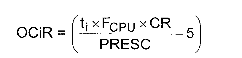
- t1 is the pulse duration (in seconds);
- t2 is the pulse period (in seconds), t1/t2 being the duty ratio;
- PRESC is a pre-scaler factor calculated as if the
CPU 12 had the target clock frequency of, e.g., 2 MHz. It is seen that the calibration ratio CR compensates for the variation of FCPU with respect to that target value. - In another embodiment, the calibration ratio CR is used by an application program stored in
memory 13 to adjust the baud rate of the SCI unit 19. The baud rate is usually proportional to the CPU frequency, which can also be adjusted by taking account of the estimated calibration ratio CR.
Claims (15)
- A method of operating a microcontroller chip (10) having a central processing unit (12), memory means (13, 14) for storing programs and data, at least one peripheral unit (18, 19) for interacting with the outside of the chip, and an internal RC oscillator (17) for providing clock signals to said central processing and peripheral units, wherein the at least one peripheral unit comprises a timer unit (18) having a counter incremented at a frequency proportional to an oscillation frequency of the RC oscillator, the method comprising the steps of:connecting an external calibration source (21) to a capture input (20) of the timer unit, the calibration source providing a calibration signal (S) having a predefined reference frequency;sampling a value of said counter on active edges of the calibration signal;processing the sampled values of said counter to derive a calibration ratio; andperforming software correction of at least one parameter handled by a program stored in the memory means based on the calibration ratio to compensate for frequency variations of the RC oscillator (17).
- A method according to claim 1, wherein the step of sampling comprises sampling the counter value on at least two consecutive active edges of the calibration signal (S), and the step of processing comprises determining a difference value between the two sampled values by taking account of any counter overflow occurring between said two consecutive active edges.
- A method according to claim 2, wherein the step of processing further comprises computing the calibration ratio as the ratio between the determined difference value and a reference value inversely proportional to the reference frequency.
- A method according to claim 2, wherein the step of processing further comprises low-pass filtering a plurality of difference values successively determined, and computing the calibration ratio as the ratio between the low-pass filtered difference value and a reference value inversely proportional to the reference frequency.
- A method according to claim 4, wherein the low-pass filtering comprises computing an average of a predetermined number of difference values falling within a capture range.
- A method according to any one of the preceding claims, wherein the predefined reference frequency is a mains frequency.
- A method according to any one of the preceding claims, wherein the at least one peripheral unit comprises a pulse width modulator unit (18), and wherein the step of performing software correction comprises adjusting a frequency and/or a duty ratio of an output signal of the pulse width modulator unit as a function of the calibration ratio.
- A method according to any one of the preceding claims, wherein the at least one peripheral unit comprises a serial communication interface unit (19) for communicating with an external circuit, and wherein the step of performing software correction comprises adjusting a baud rate of the serial communication interface unit as a function of the calibration ratio.
- A microcontroller chip, comprising:wherein the stored programs include instructions for processing the sampled values of said counter to derive a calibration ratio, and instructions for performing software correction of at least one parameter based on the calibration ratio to compensate for frequency variations of the RC oscillator (17).a central processing unit (12);memory means (13, 14) for storing programs and dataat least one peripheral unit (18, 19) for interacting with the outside of the chip, including a timer unit (18) having a counter incremented at a frequency proportional to an oscillation frequency of the RC oscillator;an internal RC oscillator (17) for providing clock signals to said central processing and peripheral units; andmeans for sampling a value of said counter on active edges of a calibration signal (S) having a predefined reference frequency, supplied at a capture input (20) of the timer unit by an external calibration source (21),
- A microcontroller chip according to claim 9, wherein the sampling means are arranged to sample the counter value on at least two consecutive active edges of the calibration signal (S), and said processing instructions comprise instructions for determining a difference value between the two sampled values by taking account of any counter overflow occurring between said two consecutive active edges.
- A microcontroller chip according to claim 10, wherein said processing instructions further comprise instructions for computing the calibration ratio as the ratio between the determined difference value and a reference value inversely proportional to the reference frequency.
- A microcontroller chip according to claim 10, wherein said processing instructions further comprise instructions for low-pass filtering a plurality of difference values successively determined, and for computing the calibration ratio as the ratio between the low-pass filtered difference value and a reference value inversely proportional to the reference frequency.
- A microcontroller chip according to claim 12, wherein the instructions for low-pass filtering comprise instructions for computing an average of a predetermined number of difference values falling within a capture range.
- A microcontroller chip according to any one of claims 9 to 13, wherein the at least one peripheral unit comprises a pulse width modulator unit (18), and wherein the instructions for performing software correction comprise instructions for adjusting a frequency and/or a duty ratio of an output signal of the pulse width modulator unit as a function of the calibration ratio.
- A microcontroller chip according to any one of claims 9 to 14, wherein the at least one peripheral unit comprises a serial communication interface unit (19) for communicating with an external circuit, and wherein the instructions for performing software correction comprise instructions for adjusting a baud rate of the serial communication interface unit as a function of the calibration ratio.
Priority Applications (3)
| Application Number | Priority Date | Filing Date | Title |
|---|---|---|---|
| DE60206149T DE60206149D1 (en) | 2002-07-05 | 2002-07-05 | Method for operating a microcontroller chip with an internal RC oscillator, and microcontroller chip for carrying out the method |
| EP02291700A EP1378998B1 (en) | 2002-07-05 | 2002-07-05 | Method of operating a microcontroller chip having an internal RC oscillator, and microcontroller chip embodying the method |
| US10/610,343 US6925402B2 (en) | 2002-07-05 | 2003-06-30 | Method of operating a microcontroller chip having an internal RC oscillator and microcontroller chip embodying the method |
Applications Claiming Priority (1)
| Application Number | Priority Date | Filing Date | Title |
|---|---|---|---|
| EP02291700A EP1378998B1 (en) | 2002-07-05 | 2002-07-05 | Method of operating a microcontroller chip having an internal RC oscillator, and microcontroller chip embodying the method |
Publications (2)
| Publication Number | Publication Date |
|---|---|
| EP1378998A1 true EP1378998A1 (en) | 2004-01-07 |
| EP1378998B1 EP1378998B1 (en) | 2005-09-14 |
Family
ID=29719782
Family Applications (1)
| Application Number | Title | Priority Date | Filing Date |
|---|---|---|---|
| EP02291700A Expired - Lifetime EP1378998B1 (en) | 2002-07-05 | 2002-07-05 | Method of operating a microcontroller chip having an internal RC oscillator, and microcontroller chip embodying the method |
Country Status (3)
| Country | Link |
|---|---|
| US (1) | US6925402B2 (en) |
| EP (1) | EP1378998B1 (en) |
| DE (1) | DE60206149D1 (en) |
Cited By (2)
| Publication number | Priority date | Publication date | Assignee | Title |
|---|---|---|---|---|
| EP3327929A3 (en) * | 2016-11-04 | 2018-08-15 | Johnson Electric S.A. | Rc oscillator, motor-driven integrated circuit, and motor device |
| CN113065173A (en) * | 2021-04-22 | 2021-07-02 | 西安电掣风云智能科技有限公司 | Encryption method and device for protecting processor embedded algorithm and storage medium |
Families Citing this family (7)
| Publication number | Priority date | Publication date | Assignee | Title |
|---|---|---|---|---|
| WO2004070937A2 (en) * | 2003-02-07 | 2004-08-19 | Philips Intellectual Property & Standards Gmbh | System and method for calibrating the clock frequency of a clock generator unit over a data line |
| US7498891B2 (en) * | 2005-10-18 | 2009-03-03 | Stmicroelectronics Pvt. Ltd. | Method for calibration of an oscillator for a microcontroller chip operation |
| CN108063617A (en) * | 2017-11-20 | 2018-05-22 | 珠海慧联科技有限公司 | The clock frequency calibration method and system of a kind of low frequency RC oscillators |
| CN111819787B (en) * | 2020-01-03 | 2023-12-15 | 深圳市汇顶科技股份有限公司 | Crystal calibration methods, chips and Bluetooth headsets |
| CN112737574B (en) * | 2020-11-30 | 2024-01-12 | 珠海格力电器股份有限公司 | Timing calibration method and related device for clock source in chip |
| CN114421890A (en) * | 2022-01-21 | 2022-04-29 | 南京扬贺扬微电子科技有限公司 | RC oscillation module and method for optimizing correction |
| CN115800922B (en) * | 2022-11-10 | 2026-05-08 | 珠海格力电器股份有限公司 | Methods for automatically calibrating the internal crystal oscillator frequency, controller chips, household appliances, storage media |
Citations (2)
| Publication number | Priority date | Publication date | Assignee | Title |
|---|---|---|---|---|
| US20010007091A1 (en) * | 1999-12-23 | 2001-07-05 | Fabrice Walter | Integrated circuit provided with means for calibrating an electronic module and method for calibrating an electronic module of an integrated circuit |
| US6326825B1 (en) * | 2001-01-18 | 2001-12-04 | Agilent Technologies, Inc. | Accurate time delay system and method utilizing an inaccurate oscillator |
Family Cites Families (2)
| Publication number | Priority date | Publication date | Assignee | Title |
|---|---|---|---|---|
| US6339413B1 (en) * | 1996-06-28 | 2002-01-15 | Microchip Technology Incorporated | Microcontroller with internal clock for liquid crystal display |
| JP2002217689A (en) * | 2001-01-17 | 2002-08-02 | Sanyo Electric Co Ltd | Frequency variable rc oscillator and microcomputer |
-
2002
- 2002-07-05 DE DE60206149T patent/DE60206149D1/en not_active Expired - Lifetime
- 2002-07-05 EP EP02291700A patent/EP1378998B1/en not_active Expired - Lifetime
-
2003
- 2003-06-30 US US10/610,343 patent/US6925402B2/en not_active Expired - Lifetime
Patent Citations (2)
| Publication number | Priority date | Publication date | Assignee | Title |
|---|---|---|---|---|
| US20010007091A1 (en) * | 1999-12-23 | 2001-07-05 | Fabrice Walter | Integrated circuit provided with means for calibrating an electronic module and method for calibrating an electronic module of an integrated circuit |
| US6326825B1 (en) * | 2001-01-18 | 2001-12-04 | Agilent Technologies, Inc. | Accurate time delay system and method utilizing an inaccurate oscillator |
Cited By (3)
| Publication number | Priority date | Publication date | Assignee | Title |
|---|---|---|---|---|
| EP3327929A3 (en) * | 2016-11-04 | 2018-08-15 | Johnson Electric S.A. | Rc oscillator, motor-driven integrated circuit, and motor device |
| US10483948B2 (en) | 2016-11-04 | 2019-11-19 | Johnson Electric International AG | RC oscillator, motor-driven integrated circuit, and motor device |
| CN113065173A (en) * | 2021-04-22 | 2021-07-02 | 西安电掣风云智能科技有限公司 | Encryption method and device for protecting processor embedded algorithm and storage medium |
Also Published As
| Publication number | Publication date |
|---|---|
| US20040068383A1 (en) | 2004-04-08 |
| EP1378998B1 (en) | 2005-09-14 |
| DE60206149D1 (en) | 2005-10-20 |
| US6925402B2 (en) | 2005-08-02 |
Similar Documents
| Publication | Publication Date | Title |
|---|---|---|
| JP5925807B2 (en) | Low power oscillator | |
| EP1378998B1 (en) | Method of operating a microcontroller chip having an internal RC oscillator, and microcontroller chip embodying the method | |
| JP4445551B2 (en) | Phase control device, pulse pattern generator using the same, and error detector | |
| US8073092B2 (en) | Automatic synchronization of an internal oscillator to an external frequency reference | |
| DE102016013983A1 (en) | Low frequency precision oscillator | |
| JP2009296571A (en) | Oscillator and method of correcting loop bandwidth of phase-locked circuit | |
| TWI517588B (en) | Electronic device, method and system for auto trimming oscillator | |
| JP2017510107A (en) | Improved low power oscillator | |
| US20050024111A1 (en) | Device for calibrating a clock signal | |
| US6639479B2 (en) | Highly stable integrated time reference | |
| EP0822479A2 (en) | Clock system | |
| JPH1065527A (en) | Phase locked loop oscillation circuit | |
| JP4643551B2 (en) | Automatic frequency monitoring circuit, electronic device, automatic frequency monitoring method, and automatic frequency monitoring program | |
| CN116184367B (en) | Calibration method and apparatus for carry chain delay | |
| EP4246811A1 (en) | System and method of controlling frequency of a digitally controlled oscillator with temperature compensation | |
| WO2007031940A2 (en) | Generating a pulse signal with a modulated duty cycle | |
| CN101124721A (en) | Digital Time Constant Tracking Technology and Device | |
| TWI533136B (en) | Frequency calibration method applicable in universal serial bus device and the related universal serial bus device | |
| JP2007281762A (en) | Filter device and semiconductor device using the same | |
| US6792060B1 (en) | Processor having an adaptable operational frequency | |
| CN112737549A (en) | Signal output frequency adjusting method and device and electronic equipment | |
| EP0744099A1 (en) | Interference dependent adaptive phase clock controller | |
| CN115800922B (en) | Methods for automatically calibrating the internal crystal oscillator frequency, controller chips, household appliances, storage media | |
| CN100582985C (en) | Method and device for adjusting signal measurement sensitivity | |
| KR101000738B1 (en) | Cut-off frequency correction circuit of filter using digital method |
Legal Events
| Date | Code | Title | Description |
|---|---|---|---|
| PUAI | Public reference made under article 153(3) epc to a published international application that has entered the european phase |
Free format text: ORIGINAL CODE: 0009012 |
|
| AK | Designated contracting states |
Kind code of ref document: A1 Designated state(s): AT BE BG CH CY CZ DE DK EE ES FI FR GB GR IE IT LI LU MC NL PT SE SK TR |
|
| AX | Request for extension of the european patent |
Extension state: AL LT LV MK RO SI |
|
| 17P | Request for examination filed |
Effective date: 20040519 |
|
| AKX | Designation fees paid |
Designated state(s): DE FR GB IT |
|
| 17Q | First examination report despatched |
Effective date: 20040831 |
|
| GRAP | Despatch of communication of intention to grant a patent |
Free format text: ORIGINAL CODE: EPIDOSNIGR1 |
|
| GRAS | Grant fee paid |
Free format text: ORIGINAL CODE: EPIDOSNIGR3 |
|
| GRAA | (expected) grant |
Free format text: ORIGINAL CODE: 0009210 |
|
| AK | Designated contracting states |
Kind code of ref document: B1 Designated state(s): DE FR GB IT |
|
| PG25 | Lapsed in a contracting state [announced via postgrant information from national office to epo] |
Ref country code: IT Free format text: LAPSE BECAUSE OF FAILURE TO SUBMIT A TRANSLATION OF THE DESCRIPTION OR TO PAY THE FEE WITHIN THE PRESCRIBED TIME-LIMIT;WARNING: LAPSES OF ITALIAN PATENTS WITH EFFECTIVE DATE BEFORE 2007 MAY HAVE OCCURRED AT ANY TIME BEFORE 2007. THE CORRECT EFFECTIVE DATE MAY BE DIFFERENT FROM THE ONE RECORDED. Effective date: 20050914 |
|
| REG | Reference to a national code |
Ref country code: GB Ref legal event code: FG4D |
|
| REF | Corresponds to: |
Ref document number: 60206149 Country of ref document: DE Date of ref document: 20051020 Kind code of ref document: P |
|
| PG25 | Lapsed in a contracting state [announced via postgrant information from national office to epo] |
Ref country code: DE Free format text: LAPSE BECAUSE OF FAILURE TO SUBMIT A TRANSLATION OF THE DESCRIPTION OR TO PAY THE FEE WITHIN THE PRESCRIBED TIME-LIMIT Effective date: 20051215 |
|
| ET | Fr: translation filed | ||
| PGFP | Annual fee paid to national office [announced via postgrant information from national office to epo] |
Ref country code: GB Payment date: 20060712 Year of fee payment: 5 |
|
| PGFP | Annual fee paid to national office [announced via postgrant information from national office to epo] |
Ref country code: FR Payment date: 20060719 Year of fee payment: 5 |
|
| PLBE | No opposition filed within time limit |
Free format text: ORIGINAL CODE: 0009261 |
|
| STAA | Information on the status of an ep patent application or granted ep patent |
Free format text: STATUS: NO OPPOSITION FILED WITHIN TIME LIMIT |
|
| 26N | No opposition filed |
Effective date: 20060615 |
|
| GBPC | Gb: european patent ceased through non-payment of renewal fee |
Effective date: 20070705 |
|
| PG25 | Lapsed in a contracting state [announced via postgrant information from national office to epo] |
Ref country code: GB Free format text: LAPSE BECAUSE OF NON-PAYMENT OF DUE FEES Effective date: 20070705 |
|
| REG | Reference to a national code |
Ref country code: FR Ref legal event code: ST Effective date: 20080331 |
|
| PG25 | Lapsed in a contracting state [announced via postgrant information from national office to epo] |
Ref country code: FR Free format text: LAPSE BECAUSE OF NON-PAYMENT OF DUE FEES Effective date: 20070731 |