EP1378892A2 - Head position control method, disk device, and servo track write method - Google Patents
Head position control method, disk device, and servo track write method Download PDFInfo
- Publication number
- EP1378892A2 EP1378892A2 EP03253869A EP03253869A EP1378892A2 EP 1378892 A2 EP1378892 A2 EP 1378892A2 EP 03253869 A EP03253869 A EP 03253869A EP 03253869 A EP03253869 A EP 03253869A EP 1378892 A2 EP1378892 A2 EP 1378892A2
- Authority
- EP
- European Patent Office
- Prior art keywords
- head
- demodulation
- disk
- virtual circular
- velocity
- Prior art date
- Legal status (The legal status is an assumption and is not a legal conclusion. Google has not performed a legal analysis and makes no representation as to the accuracy of the status listed.)
- Granted
Links
Images





Classifications
-
- G—PHYSICS
- G11—INFORMATION STORAGE
- G11B—INFORMATION STORAGE BASED ON RELATIVE MOVEMENT BETWEEN RECORD CARRIER AND TRANSDUCER
- G11B21/00—Head arrangements not specific to the method of recording or reproducing
- G11B21/02—Driving or moving of heads
- G11B21/10—Track finding or aligning by moving the head ; Provisions for maintaining alignment of the head relative to the track during transducing operation, i.e. track following
-
- G—PHYSICS
- G11—INFORMATION STORAGE
- G11B—INFORMATION STORAGE BASED ON RELATIVE MOVEMENT BETWEEN RECORD CARRIER AND TRANSDUCER
- G11B5/00—Recording by magnetisation or demagnetisation of a record carrier; Reproducing by magnetic means; Record carriers therefor
- G11B5/48—Disposition or mounting of heads or head supports relative to record carriers ; arrangements of heads, e.g. for scanning the record carrier to increase the relative speed
- G11B5/58—Disposition or mounting of heads or head supports relative to record carriers ; arrangements of heads, e.g. for scanning the record carrier to increase the relative speed with provision for moving the head for the purpose of maintaining alignment of the head relative to the record carrier during transducing operation, e.g. to compensate for surface irregularities of the latter or for track following
- G11B5/596—Disposition or mounting of heads or head supports relative to record carriers ; arrangements of heads, e.g. for scanning the record carrier to increase the relative speed with provision for moving the head for the purpose of maintaining alignment of the head relative to the record carrier during transducing operation, e.g. to compensate for surface irregularities of the latter or for track following for track following on disks
- G11B5/59633—Servo formatting
-
- G—PHYSICS
- G11—INFORMATION STORAGE
- G11B—INFORMATION STORAGE BASED ON RELATIVE MOVEMENT BETWEEN RECORD CARRIER AND TRANSDUCER
- G11B5/00—Recording by magnetisation or demagnetisation of a record carrier; Reproducing by magnetic means; Record carriers therefor
- G11B5/48—Disposition or mounting of heads or head supports relative to record carriers ; arrangements of heads, e.g. for scanning the record carrier to increase the relative speed
- G11B5/58—Disposition or mounting of heads or head supports relative to record carriers ; arrangements of heads, e.g. for scanning the record carrier to increase the relative speed with provision for moving the head for the purpose of maintaining alignment of the head relative to the record carrier during transducing operation, e.g. to compensate for surface irregularities of the latter or for track following
- G11B5/596—Disposition or mounting of heads or head supports relative to record carriers ; arrangements of heads, e.g. for scanning the record carrier to increase the relative speed with provision for moving the head for the purpose of maintaining alignment of the head relative to the record carrier during transducing operation, e.g. to compensate for surface irregularities of the latter or for track following for track following on disks
- G11B5/59633—Servo formatting
- G11B5/59644—Acquisition or selection of servo format from a system reference
Definitions
- the present invention relates to a head position control method, a disk device and a servo track write method for positioning a head for recording/regenerating data on a disk on a target track of the disk, and more particularly to a head position control method, disk device and servo track write method for demodulating servo signals recorded on an eccentric disk and obtaining the position of a head.
- a disk storage device which records or regenerates data to/from a rotating disk medium is widely used as a storage device for data.
- the disk device is comprised of a disk 94 for storing data, a spindle motor 96 for rotating the disk 94, a head 90 for recording/regenerating information on the disk 94, and an actuator 92 for moving the head 90 to a target position.
- Typical of such a device is a magnetic disk (HDD: Hard Disk Drive) and an optical disk device (DVD-ROM, MO).
- position signals 100 for detecting a position of the head 90 are recorded on the disk 94.
- the position signal 100 is comprised of a servo mark, track number and offset information.
- the current position of the head 90 can be obtained using the track number and offset information.
- the difference between this position information and the target position is determined, and calculation is performed according to the position error amount, so as to supply the drive amount for driving the actuator 92, such as current in the case of a VCM (Voice Coil Motor), and voltage in the case of a piezo-electric actuator.
- VCM Vehicle Coil Motor
- a method for recording the servo signal by an external STW (Servo Track Write) device has been proposed instead of a conventional STW method, where the disk device itself records the servo signal.
- this method was proposed in the Japanese Patent Laid-Open No. 03-073406 "Servo information writing method for a magnetic disk device", (published on March 28, 1991).
- a position orbit (virtual circular orbit) is provided so as to ignore the eccentricity, as shown in Fig. 20, removing this orbit from the demodulation signals of the head, in order to obtain a demodulation position, and the actuator is controlled with the demodulation position.
- the head 90 is positioned on the circular orbit 110 with the rotation axis 98 of the spindle motor as the center, using the position signal with respect to the circular orbit of the eccentric position signal 100, and reads data from/writes data to the disk 94.
- the orbit 110 of the head 90 is represented with a line, as shown in Fig. 21, then the orbit 110 crosses the orbit 102 of the position signal indicated by a sine wave.
- FIG. 22 is a diagram depicting 2-phase servo position signals
- Fig. 23 is a block diagram depicting the position demodulation circuit thereof
- Fig. 24 to Fig. 26 are diagrams depicting the position demodulation signals.
- the position signal (servo signal) is comprised of a servo mark, Gray code (track number), index, and offset signals (PosA - PosD).
- the track number and the offset signals (PosA - PosD) are separated from the position signals from the head 90 in the block 120, and the 2-phase servo signals PosN and PosQ are calculated as follows.
- the position demodulation is performed so that either PosN or PosQ, whichever is smaller in the block 122, is used as Pos1. In other words, as shown in Fig. 22, either PosN or PosQ, whichever is smaller, is selected.
- the position sensitivity gain 124 changes the gain according to the track position.
- Such a demodulation method is described in detail in Japanese Patent Laid-Open No. 8-195044 (published on July 30, 1996), for example.
- a crossover (switching) of PosN and PosQ is generated during demodulation, as shown in Fig. 24. If the head 90 crosses the position signal diagonally, as shown in Fig. 22, that is when the head 90 has velocity, an error occurs to the demodulation positions by PosN and PosQ, and a velocity offset of NQ is generated. In other words, the 2-phase servo signals PosN and PosQ can be observed with a 1/4 phase shift in the track direction, as shown in Fig. 24, only when the velocity of the actuator is zero.
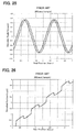
- Fig 25 shows the result of simulating the status of PosN and PosQ when the head moves at a 20 track/sample in the device.
- Fig. 25 shows, the phase relationship between PosN and PosQ is shifted.
- Fig. 26 shows the result of calculating the demodulation position at this time, and the switching of PosN and PosQ makes correct position demodulation impossible.
- Track pitch in particular is currently narrow because of the increase in recording densities, where the number of eccentric tracks increases and higher precision positioning is requested, so the difference in correction velocity can no longer be ignored.
- a head position control method for controlling the position of a head on a virtual circular orbit of a disk, comprising the steps of: demodulating a position signal of the disk read by the head to obtain a demodulation result, calculating a demodulation position from the demodulation result, subtracting the positional fluctuation caused by the eccentricity of the disk from the demodulation position, calculating a control amount according to the positional error between the demodulation position after subtraction and a target position, and controlling an actuator for driving the head by the control amount, wherein the calculation step comprises a step of correcting the demodulation result with a correction value according to the velocity of the virtual circular orbit reference of the head, and the relative velocity between the virtual circular orbit and the position signal of the disk, and calculating the demodulation position.
- a disk device for controlling a position of a head on a virtual circular orbit of a disk, comprising a head for reading a position signal of the disk, an actuator for driving the head, and a control unit which demodulates a position signal from the head and controls the actuator for driving the head, wherein the control unit corrects a demodulation result with a correction value according to a velocity of the virtual circular orbit reference of the head, and a relative velocity between the virtual circular orbit and the position signal of the disk, calculates a demodulation position, subtracts the positional oscillation caused by the eccentricity of the disk from the demodulation position, and calculates a control amount of the actuator according to the positional error between the demodulation position after subtraction and a target position.
- the velocity offset correction of the 2-phase servo signal is performed with both the head velocity of the virtual circular orbit reference and the relative velocity of the virtual circular orbit and the position signal, so head position control at higher precision is possible even if virtual circular orbit control is performed. Therefore even if the track pitch of the disk becomes narrower and the number of eccentric tracks increases, virtual circular orbit control at higher precision is possible, and the read/write performance can be improved.
- the demodulation step may comprise a step of demodulating first position information and second position information, where phases are mutually different from the above mentioned position signals by the area demodulation. Since the area demodulation method using the first and second position information is used, the virtual circular orbit control can be easily performed.
- the calculation step may further comprise a step of combining the first position information and the second position information with predetermined weights, and calculating the demodulation position. Since demodulation by combining the first and second position information is included, a demodulation position without switching the step difference can be obtained.
- the calculation step may comprise a step of correcting the first position information with a first correction value according to the velocity of the virtual circular orbit reference of the head and the relative velocity of the virtual circular orbit and the position signal of the disk, and correcting the second position information with a second correction value according to the velocity of the virtual circular orbit reference of the head and the relative velocity of the virtual circular orbit and the position signal of the disk. Since the velocity offset is corrected according to the recording position of the first and second position information, the velocity offset correction can be more accurately performed.
- the calculation step may further comprise a step of calculating the demodulation position by multiplying the first position information by a predetermined weight M, multiplying the second position information by another predetermined weight (1 - M), and combining these multiplication results.
- the first aspect of the present invention may further comprise a step of calculating the relative velocity by differentiating a virtual circular position orbit for subtracting the positional oscillation. Since the relative velocity is obtained using the virtual circular position orbit, it is unnecessary to save data separately, and the relative position synchronizing with the virtual circular position orbit can be obtained.
- a servo track write method for writing a position signal to a mounted disk comprising the steps of: demodulating a position signal of the disk read by a head to obtain a demodulation result, calculating a demodulation position by correcting the demodulation result by a correction value according to the velocity of a virtual circular orbit reference of the head and a relative velocity of the virtual circular orbit and the position signal of the disk, subtracting the positional oscillation caused by the eccentricity of the disk from the demodulation position, calculating a control amount according to the positional error between the demodulation position after subtraction and a target position, so as to control an actuator for driving the head, and rewriting the position signal along the virtual circular orbit of the head.
- the velocity offset correction of the 2-phase servo signal is performed with both the head velocity of the virtual circular orbit reference and the relative velocity of the virtual circular orbit and the position signal, so the position signal can be rewritten at higher precision by the virtual circular orbit control. Therefore even if the track pitch of the disk becomes narrower and the number of eccentric tracks increases, virtual circular orbit control at higher precision is possible, and the read/write performance can be improved.
- the demodulating step may further comprise a step of demodulating a position signal of the disk, where the position signals have been written outside the device where the disk is mounted. Therefore virtual circular control, which does not follow up eccentricity, can be implemented at high precision even if a disk where position signals have been written outside is used.
- Embodiments of the present invention will now be described with reference to a disk storage device, position demodulation system of a first configuration, position demodulation system of a second configuration, actual examples, a servo track write method, and other embodiments, but the present invention is not limited to the following embodiments described for illustration only.
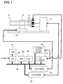
- Fig. 1 is a diagram depicting the configuration of the disk storage device of an embodiment of the present invention
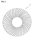
- Fig. 2 is a diagram depicting the arrangement of position signals on the magnetic disk in Fig. 1
- Fig. 3 is a diagram depicting the configuration of the position signals of the magnetic disk in Fig. 1 and Fig. 2
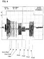
- Fig. 4 is a diagram depicting the wave form of the read position.
- Fig. 1 shows a magnetic disk device as the disk storage device.
- a magnetic disk 10 which is a magnetic storage medium, is disposed on the rotation axis 19 of the spindle motor 18.
- the spindle motor 18 rotates the magnetic disk 10.
- An actuator (VCM) 14 has a magnetic head 12 at the tip, and moves the magnetic head 12 in the radial direction of the magnetic disk 10.
- Each magnetic head 12 is comprised of read elements and write elements. Each magnetic head 12 is constructed by layering the read elements, including a magnetic resistance element, on a slider, and layering the write elements, including the write coil, thereon.
- servo signals are arranged in the circumferential direction at an equal interval from the outer circle to the inner circle.
- Each track is comprised of a plurality of sectors, and the solid line in Fig. 2 shows the recording position of the servo signal.
- the position signal is comprised of a servo mark Servo Mark, track number Gray Code, index Index, and offset information PosA, PosB, PosC and PosD.
- Fig. 4 is a diagram depicting the signal wave form when the position signal in Fig. 3 is read by the head 12.
- a position of the magnetic head in the radial direction is detected.
- the position of the magnetic head in the circumferential direction is obtained. For example, the sector number when the index signal is detected is set to '0', which is incremented each time a servo signal is detected, so as to obtain the sector number of each sector of the track.
- the sector number of this servo signal becomes a reference when the data is recorded or regenerated. There is one index signal per track. A sector number may be created instead of the index signal.
- Fig. 5 shows an example of seek control of the actuator, which is performed by the MCU 28 in Fig. 1.
- the MCU 28 confirms the position of the actuator, performs servo computation, and supplies an appropriate current to the VCM 14.
- Fig. 5 shows the transition of control from seek start, for moving the head 12 from a certain track position to the target track position, the current of the actuator 14, velocity of the actuator (head), and the position of the actuator (head).
- the head 12 can be moved to the target position by transiting as coarse control, settling control, and following control.
- the coarse control is basically velocity control
- the settling control and following control are basically position controls, and for both cases, the current position of the head must be detected.
- servo signals are recorded on the magnetic disk in advance, as shown in Fig. 2.
- a servo mark to indicate the start position of a servo signal a Gray code to indicate a track number, an index signal and PosA - PosD to indicate offset as such, are recorded.
- These signals are read by the magnetic head, the position detection circuit 20 converts these servo signals into digital values, and the MCU 28 demodulates the position and controls the actuator 14, as described in Fig. 6 and later.
- the signal demodulation section 40 separates the track number and the offset signals (PosA - PosD) from the position signals from the head 12 (see Fig. 22).
- the arithmetic unit 42 and 44 calculate the 2-phase servo signals PosN and PosQ by the following computations respectively.
- PosN PosA - PosB
- PosQ PosC - PosD
- the multipliers 48 and 50 multiply PosN and PosQ by the position sensitivity gain from the position sensitivity gain table 46.
- the position sensitivity gain is a conversion factor for determining the positions using PosN and PosQ, and changes according to the track position.
- the table 46 stores the position sensitivity gain for each zone, so that the position sensitivity gain of a zone according to the demodulated track position is read. This position sensitivity gain correction is described in detail in Japanese Patent Laid-Open No. 8-195044 (published on July 30, 1996), for example.
- the position demodulation section 68 adds the offset (difference between positions of the read and write elements) and the position Pos1 to the demodulated track number.
- the virtual circular orbit table 62 is created.
- the virtual circular orbit is created to synchronize with the sector on the disk 10, and the phase and amplitude thereof varies depending on the device and the head.
- ⁇ is a rotation angle frequency of the disk.
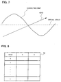
- the values of the factors S and C are stored in the table 62 for each head.
- Fig. 8 is a diagram depicting the virtual circular orbit table 62 where the sine wave factor S and the cosine wave factor C are stored for each head, 0, 1, . . . n.
- the velocity V of the actuator is a velocity of a circular orbit reference where the head follows up. Therefore in the case when the head does not follow up the circular orbit of the servo signal and is positioned on the virtual circular orbit, as in the case of the present configuration, an error ⁇ V, for the amount of the relative velocity between the virtual circular orbit for positioning and the servo signal on the disk, occurs.
- the corrected orbit for positioning the head on the virtual circular orbit exhibits a sine wave, so the relative velocity is a cosine wave, which can be easily calculated.
- the virtual circular orbit is generated synchronizing with the sectors on the disk 10, as mentioned above, and the phase and the amplitude thereof vary depending on the device and the head.
- the values of the factor S of the sine wave and the factor C of the cosine wave are stored for each head.
- the table of the values of the factors S and C may be provided for each location of the disk in the radial direction.
- the velocity of the actuator increases even more.
- the velocity V is constantly calculated during seek control, so that the current velocity and the velocity with the next sample are always known. So the velocity V due to the seek control is added with the above mentioned velocity ⁇ V due to the orbit by the adder 66, and is used for the velocity offset correction of PosN and PosQ.
- the values of the velocity offset are added to the PosN and PosQ by the adders 54 and 56.
- This velocity offset value is determined by the following formulas.
- the factor by which the velocity is multiplied can be uniquely determined from the specification of the servo signals shown in Fig. 3 (from bit 0 of Gray Code to the boundary of PosA and PosB and the boundary of PosC and PosD), and is set at the gain of the amplifiers 58 and 60 respectively.
- PosN offset velocity x (time between Gray Code Bit 0 and boundary of PosA and PosB) / sampling period
- PosQ offset velocity x (time between Gray Code Bit 0 and boundary of PosC and PosB) / sampling period
- the factor is determined from the time between the bit 0 of the Gray Code (track number) and the boundary of PosA and PosB, or the boundary of PosC and PosD.
- the relative velocity can be calculated from a known sine wave position orbit (position is Sin ⁇ velocity is Cos), so the offset of PosN and PosQ during tracking can be uniquely determined.
- both the position orbit and the velocity orbit can be obtained from the output of the table 62 of the virtual circular orbit.
- the velocity ⁇ V is added with the relative velocity V of the actuator 14 from the virtual circular orbit, and the results are input to the demodulation sections of the PosN and PosQ. There the velocity ⁇ V and the relative velocity V are combined and used to calculate a position.
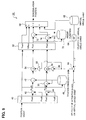
- Fig. 9 is a block diagram depicting the position demodulation system according to a second configuration
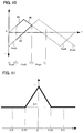
- Fig. 10 is a diagram depicting the NQ combining demodulation operation thereof
- Fig. 11 is a diagram depicting the weight function of the NQ combining demodulation operation thereof
- Fig. 12 is a diagram depicting the NQ combining demodulation operation based on the weight function.
- the position demodulation system in Fig. 9 is executed by the MCU 28 in Fig. 1.
- the MCU 28 performs a known servo computation (e.g. observer control) using the demodulation position in Fig. 9 as the current position, and calculates the control amount of the VCM 14.
- Fig. 9 the same reference numerals have been assigned to the same components as those described in Fig. 6, and the signal demodulation section 40 separates the track number and the offset signals (PosA - PosD) from the position signals from the head 12 (see Fig. 22).
- the computing units 42 and 44 calculate the 2-phase servo signals PosN and PosQ respectively.
- the velocity of the virtual circular orbit at this time is obtained by differentiating the position orbit.
- Velocity of orbit ⁇ S [Head] x cos ( ⁇ t) - C [Head] x sin ( ⁇ t) ⁇ / ⁇ Therefore the velocity ⁇ V of the orbit is calculated from the position orbit using the differentiator 64 which differentiates the position orbit, and velocity V, due to the seek control, is added with the above mentioned velocity ⁇ V due to the orbit by the adder 66, and is used for the velocity offset correction of PosN and PosQ.
- the values of the velocity offset to be added by the adders 54 and 56 are determined by the following formulas.
- the factor by which the velocity is multiplied can be uniquely determined from the specification of the servo signals shown in Fig. 3, and is set as the gain of the amplifiers 58 and 60 respectively.
- PosN offset velocity x (time between Gray Code Bit 0 and boundary of PosA and PosB) / sampling period
- PosQ offset velocity x (time between Gray Code Bit 0 and boundary of PosC and PosD) / sampling period
- both the position orbit and the velocity orbit can be obtained from the output of the table 62 of the virtual circular orbit.
- the velocity ⁇ V is added with the relative velocity V of the actuator 14 from the virtual circular orbit.
- PosN offset value and the PosQ offset value obtained from the velocity (V + ⁇ V) are added to PosN and PosQ by the adders 54 and 56, and the results are input to the demodulation section 52.
- the position demodulation method using the PosN and PosQ combining demodulation method which the present inventors proposed in Japanese Patent Application No. 2001-269871 (filed on Sept. 6, 2001) "Position demodulation method and circuit of a disk device", is used.
- the step difference due to the switching of PosN and PosQ is generated, so the NQ combining demodulation solves the influence of the step difference due to the crossing over the boundary of PosN and PosQ by demodulating PosN and PosQ and combining PosN and PosQ.
- Fig. 10 shows the position information PosN and PosQ calculated by the adders 42 and 44 in Fig. 9.
- position demodulation is performed not by selecting one of these but by using both.
- Fig. 10 shows, in a conventional demodulation method, one of PosN and PosQ, whichever absolute value is smaller, is selected as the demodulation position.
- positions are demodulated using the bold line 84 for PosQ and bold lines 86 and 88 for PosN in a same block.
- Fig. 12 is a characteristic diagram when positions are demodulated using PosN and PosQ in Fig. 10 respectively, where the ordinate is the demodulated detection position and the abscissa is the actual position.
- the position sensitivity gain including an error, is indicated by k, and the detection (demodulation) position by kx. If the position sensitivity gain is a correct value, the linear characteristic detection positions in the line 90, without the step differences caused by switching PosN and PosQ as seen in prior art, can be obtained.
- PosQ exhibits the characteristic of line 90
- PosN exhibits the characteristic of lines 92 and 95 with the above mentioned bold line block as the center. Therefore if PosN and PosQ are switched as in prior art, a switching step difference is generated when PosN crosses over to PosQ (-0.25) and when PosQ crosses over to PosN (+0.25).
- the NQ combining demodulation method modulates the positions by combining PosN and PosQ, and the principle thereof will be described.
- the characteristics of line 90 and line 92 are expressed as follows with formulas ya and yb, where the ordinate is y.
- y k (x - 0.5) + 0.5
- the weight gain M must be a linear function of the actual position x.
- the weight function in Fig. 11 is stored in the weight function table 70.
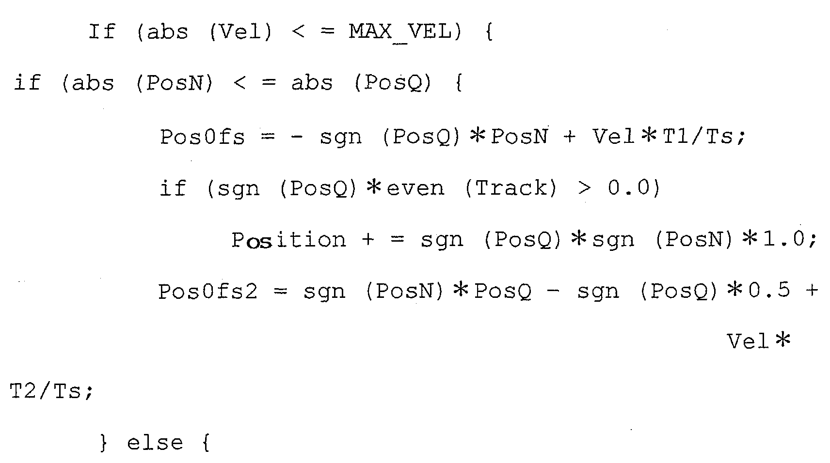
- the demodulation section 52 compares the absolute values abs of PosN and PosQ, and calculates Pos1 and Pos2 according to the comparison result. This is given by the following formulas.
- the position demodulation section 68 adds the offset (difference between the positions of the read and write elements) and the corrected positions Pos1 and Pos2 to the demodulated track numbers, subtracts the position orbit obtained from the virtual circular orbit table 62, and outputs the demodulation positions.
- This hard disk drive is a device where the rotation frequency of the disk is 4200 rpm, and the track pitch of the disk is 61500 TPI.
- Fig. 13 to Fig. 16 show the experiment result.
- servo signals are recorded on a disk in advance by an external STW device, and the disk is then assembled as an HDD. Therefore eccentricity exists from the beginning. In a state where the head is following up tracks on the disk, correction current required for following up the eccentricity is flowing, and the current oscillates in a sinusoidal manner.
- Fig. 13 is a comparison example, where the index signal, the observation position (position error signal) and VCM current when the sinusoidal position orbit has a ⁇ 0 track amplitude, that is when virtual circular control is not performed, are shown on a time axis. Since the observation positions are equalized, the RPE (Repeatable Position Error) is seen.
- Fig. 14 shows another comparison example apart from Fig. 13, where the index signal, the observation position (position error signal) and the VCM current when a ⁇ 64 track position orbit is provided as the sinusoidal orbit (virtual circular control is performed), are shown on a time axis. Positioning accuracy clearly decreases. This is largely because velocity offset correction is not performed, and also because demodulation is performed crossing over the demodulation boundary between PosN and PosQ.
- Fig. 15 is an example where the index signal, observation position and VCM current, when NQ velocity offset correction and NQ combining demodulation are performed in the virtual circular control in Fig. 14, are shown on a time axis. Even if a ⁇ 64 track position orbit is provided and virtual circular control is performed, the position error clearly decreases in comparison with the above example shown in Fig. 14. In this way, by adding NQ velocity offset correction along with NQ combining demodulation, positional error deterioration in virtual circular control of an area demodulation method can be avoided.
- Fig. 16 is the example result when the position orbit amplitude is increased up to ⁇ 128 tracks in the virtual circular control in Fig. 15.
- the position error is not 0, and it oscillates.
- This problem occurs because the velocity, due to the position orbit, is too high and a block, where the phase relationship between PosN and PosQ is reversed, is generated, as described in the above mentioned application (Japanese Patent Laid-Open No. 2001-256741). In such a status, the problem cannot be solved regardless how NQ velocity offset correction is performed.
- the critical velocity at which the phase relationship between PosN and PosQ does not reverse determines the upper limit of the position orbit amplitude of the virtual circular control.
- a first method is the same as using a regular HDD device.
- servo signals have been recorded on the disk alone by an external STW device, one or a plurality of such disks are mounted on the HDD device. In this case, problems lie in the difference of eccentricity of the disks.
- FIG. 17 is a diagram depicting an embodiment of the servo track write method of the third aspect of the present invention.
- servo signals are recorded on a disk.
- one such disk 10-1 is mounted on the disk device 1.
- a plurality of disks 10-1, where no servo signals have been recorded, are mounted on the disk device 1.
- the positioning control of the head 12-1 is performed on the disk face 10-1 where servo signals have been recorded using virtual circular control so as not to follow up the eccentricity.
- the new servo signals are recorded on surfaces of the disks 10-1 and 10-2, in the areas between the original servo signals of the disk 10-1 for all the heads, 12-1 and 12-2.
- the original servo signals of the original disk 10-1 are erased.
- servo signals can be recorded on all the disks from these servo signals without eccentricity.
- virtual circular control is used only for servo track write, and after servo track write, demodulation is performed with normal servo signals without virtual circular control, and with this method, the head position is controlled.
- a disk storage device has been described using a magnetic disk device, but the embodiments of the present invention can be applied to other disk storage devices, such as an optical disk device and a magneto optical disk device.
- the correction method of the head during switching is not limited to two or more disks, but can be applied between heads used for different surfaces (e.g. the front and back) of one disk.
- the shape of the disk is also not limited to a circular disk shape, but may be a card shape.
- the velocity offset correction of 2-phase signals is performed with both the head velocity of the virtual circular orbit reference and the relative velocity of the virtual circular orbit and the position signals, so head position control at higher precision is possible even if virtual circular orbit control is performed. Therefore, even if the track pitch of the disk becomes narrower and the number of eccentric tracks increases, virtual circular orbit control at higher precision can be performed, and the read/write performance can be improved.
Landscapes
- Moving Of The Head To Find And Align With The Track (AREA)
Abstract
Description

Claims (14)
- A head position control method for controlling a position of a head on a virtual circular orbit of a disk, comprising the steps of:demodulating a position signal of said disk read by said head to obtain a demodulation result;calculating a demodulation position by correcting said demodulation result with a correction value according to the velocity of a virtual circular orbit reference of said head and the relative velocity of said virtual circular orbit and the position signal of said disk;subtracting the positional oscillation caused by the eccentricity of said disk from said demodulation position;calculating a control amount according to the positional error between said demodulation position after subtraction and a target position; andcontrolling an actuator for driving said head by said control amount.
- The head position control method according to Claim 1, wherein said demodulation step comprises a step of demodulating first position information and second position information, of which phases are mutually different, from said position signal by area demodulation.
- The head position control method according to Claim 2, wherein said calculation step comprises a step of calculating said demodulation position by combining said first position information and said second position information with predetermined weights.
- The head position control method according to Claim 2, wherein said calculation step comprises a step of correcting said first position information with a first correction value according to the velocity of said virtual circular orbit reference of said head and the relative velocity of said virtual circular orbit and the position signal of said disk, and correcting said second position information with a second correction value according to the velocity of said virtual circular orbit reference of said head and the relative velocity of said virtual circular orbit and the position signal of said disk.
- The head position control method according to Claim 3, wherein said calculation step comprises a step of calculating said demodulation position by multiplying said first position information by a predetermined weight M, multiplying said second position information by another predetermined weight (1 - M), and combining these multiplication results.
- The head position control method according to any preceding claim, further comprising a step of calculating said relative velocity by differentiating a virtual circular position orbit for subtracting said positional oscillation.
- A disk device for controlling a position of a head on a virtual circular orbit of a disk, comprising:wherein said control unit corrects a demodulation result with a correction value according to a velocity of said virtual circular orbit reference of said head and a relative velocity of said virtual circular orbit and said position signal of said disk, calculates a demodulation position, subtracts positional oscillation caused by the eccentricity of said disk from said demodulation position, and calculates a control amount of said actuator according to the positional error between said demodulation position after subtraction and a target position.a head for reading a position signal of said disk;an actuator for driving said head; anda control unit which demodulates a position signal from said head and controls said actuator for driving said head,
- The disk device according to Claim 7, wherein said control unit demodulates first position information and second position information, of which phases are mutually different, from said position signal by area demodulation.
- The disk device according to Claim 8, wherein said control unit calculates said demodulation position by combining said first position information and said second position information with predetermined weights.
- The disk device according to Claim 8, wherein said control unit corrects said first position information with a first correction value according to the velocity of said virtual circular orbit reference of said head and the relative velocity of said virtual circular orbit and the position signal of said disk, and corrects said second position information with a second correction value according to the velocity of said virtual circular orbit reference of said head and the relative velocity of said virtual circular orbit and the position signal of said disk.
- The disk device according to Claim 8, wherein said control unit calculates said demodulation position by multiplying said first position information by a predetermined weight M, multiplying said second position information by another predetermined weight (1 - M), and combining these multiplication results.
- The disk device according to any of Claims 7 to 11, wherein said control unit has a table for storing said positional oscillation to be subtracted, and calculates said relative velocity by differentiating a positional oscillation of said table.
- A servo track write method for writing a position signal to a mounted disk, comprising the steps of:demodulating a position signal of said disk read by a head to obtain a demodulation result;calculating a demodulation position by correcting said demodulation result with a correction value according to the velocity of a virtual circular orbit reference of said head and the relative velocity of said virtual circular orbit and the position signal of said disk;subtracting positional oscillation caused by eccentricity of said disk from said demodulation position;calculating a control amount according to the positional error between said demodulation position after subtraction and a target position;controlling an actuator for driving said head; andrewriting said position signal along the virtual circular orbit of said head.
- The servo track write method according to Claim 13 wherein said demodulation step comprises a step of demodulating a position signal of said disk where said position signals have been written outside the device where said disk is mounted.
Applications Claiming Priority (2)
| Application Number | Priority Date | Filing Date | Title |
|---|---|---|---|
| JP2002195037A JP4660055B2 (en) | 2002-07-03 | 2002-07-03 | Head position control method, disk device and servo track write method |
| JP2002195037 | 2002-07-03 |
Publications (3)
| Publication Number | Publication Date |
|---|---|
| EP1378892A2 true EP1378892A2 (en) | 2004-01-07 |
| EP1378892A3 EP1378892A3 (en) | 2005-12-21 |
| EP1378892B1 EP1378892B1 (en) | 2008-08-06 |
Family
ID=29720282
Family Applications (1)
| Application Number | Title | Priority Date | Filing Date |
|---|---|---|---|
| EP03253869A Expired - Lifetime EP1378892B1 (en) | 2002-07-03 | 2003-06-19 | Head position control method, disk device, and servo track write method |
Country Status (6)
| Country | Link |
|---|---|
| US (1) | US6989956B2 (en) |
| EP (1) | EP1378892B1 (en) |
| JP (1) | JP4660055B2 (en) |
| KR (1) | KR20040004128A (en) |
| CN (1) | CN1223996C (en) |
| DE (1) | DE60322632D1 (en) |
Families Citing this family (22)
| Publication number | Priority date | Publication date | Assignee | Title |
|---|---|---|---|---|
| JP2005025826A (en) * | 2003-06-30 | 2005-01-27 | Toshiba Corp | Disk storage device and servo writing method |
| JP2005050257A (en) * | 2003-07-31 | 2005-02-24 | Toshiba Corp | Electronic device having serial ATA interface and signal amplitude automatic adjustment method |
| KR100594252B1 (en) * | 2004-02-17 | 2006-06-30 | 삼성전자주식회사 | Method of controlling head movement in data storage device and disk drive using same |
| US7405894B2 (en) * | 2004-07-08 | 2008-07-29 | Broadcom Corporation | Frequency, phase, and gain estimation technique for use in a read channel receiver of a hard disk drive |
| CN101223590B (en) * | 2005-07-15 | 2011-06-29 | 皇家飞利浦电子股份有限公司 | Method and system for correction of errors |
| CN100476955C (en) * | 2005-09-15 | 2009-04-08 | 联咏科技股份有限公司 | Method and circuit for canceling deflection variation of disc storage system |
| US8089718B2 (en) * | 2006-01-10 | 2012-01-03 | Hitachi Global Technologies, Netherlands B.V. | Method and apparatus for increasing storage capacity of a hard disk drive |
| JP4439480B2 (en) | 2006-03-03 | 2010-03-24 | 東芝ストレージデバイス株式会社 | POSITIONING CONTROL DEVICE, DISC DEVICE, AND POSITIONING CONTROL METHOD |
| JP2008176865A (en) * | 2007-01-19 | 2008-07-31 | Fujitsu Ltd | Storage device, control device |
| US7876523B1 (en) | 2009-08-07 | 2011-01-25 | Western Digital Technologies, Inc. | Disk drive initializing position feedforward compensation with velocity feedforward compensation |
| US8189286B1 (en) | 2010-05-21 | 2012-05-29 | Western Digital Technologies, Inc. | Disk drive employing velocity insensitive servo burst pattern |
| US7916422B1 (en) | 2010-05-28 | 2011-03-29 | Western Digital Technologies, Inc. | Disk drive rotating phase based servo bursts based on radial location of head |
| US8077428B1 (en) | 2010-06-23 | 2011-12-13 | Western Digital Technologies, Inc. | Disk drive correcting position error signal based on velocity of head |
| US8531798B1 (en) | 2010-12-13 | 2013-09-10 | Western Digital Technologies, Inc. | Disk drive adjusting servo burst signals to compensate for radial velocity of the head |
| JP5060612B2 (en) * | 2010-12-24 | 2012-10-31 | 株式会社東芝 | DISK STORAGE DEVICE, DISK STORAGE DEVICE CONTROLLER, CONTROL METHOD USING DISK STORAGE DEVICE, AND ELECTRONIC DEVICE |
| JP5162007B2 (en) | 2011-06-10 | 2013-03-13 | 株式会社東芝 | Position demodulation apparatus and position demodulation method |
| JP2013157065A (en) * | 2012-01-31 | 2013-08-15 | Toshiba Corp | Magnetic disk device and method of controlling head position |
| US8953266B2 (en) * | 2012-08-24 | 2015-02-10 | HGST Netherlands B.V. | Method and structure for improving performance and storage density in a data storage device |
| CN104575528A (en) * | 2013-10-15 | 2015-04-29 | 株式会社东芝 | Head position demodulating method and magnetic disk device |
| JP2020205128A (en) * | 2019-06-14 | 2020-12-24 | 株式会社東芝 | How to control magnetic disk drive and servo light |
| JP2023095170A (en) * | 2021-12-24 | 2023-07-06 | 株式会社東芝 | Magnetic disk device and SSW method |
| JP2024043998A (en) | 2022-09-20 | 2024-04-02 | 株式会社東芝 | disk device |
Family Cites Families (13)
| Publication number | Priority date | Publication date | Assignee | Title |
|---|---|---|---|---|
| US3725764A (en) * | 1971-04-01 | 1973-04-03 | Ibm | Servo positioning system for magnetic disk memory including radial runout servo compensation |
| JP3781380B2 (en) | 1995-01-13 | 2006-05-31 | 富士通株式会社 | Position signal demodulation method |
| JP3295940B2 (en) * | 1995-03-17 | 2002-06-24 | 株式会社日立製作所 | Magnetic recording device and magneto-optical recording device |
| JPH09128915A (en) | 1995-11-02 | 1997-05-16 | Matsushita Electric Ind Co Ltd | Fixed magnetic recording device |
| US5739972A (en) * | 1996-01-02 | 1998-04-14 | Ibm | Method and apparatus for positioning a magnetoresistive head using thermal response to servo information on the record medium |
| JP2965062B2 (en) | 1996-06-10 | 1999-10-18 | 富士通株式会社 | Disk device and head position control method for disk device |
| JP3859282B2 (en) | 1996-12-10 | 2006-12-20 | 富士通株式会社 | Servo pattern writing method of magnetic disk device and magnetic disk device |
| US6137753A (en) * | 1997-04-14 | 2000-10-24 | Oak Technology, Inc. | Runout calibration for disc drive system |
| US6411461B1 (en) * | 1998-02-03 | 2002-06-25 | Seagate Technology Llc | Data collection system and method for zero acceleration path correction |
| CN1145149C (en) * | 1999-04-21 | 2004-04-07 | 西加特技术有限责任公司 | Method and servo circuit for moving control head in disk drive apparatus |
| JP3683155B2 (en) | 2000-03-08 | 2005-08-17 | 富士通株式会社 | Head positioning control method and apparatus for disk device |
| JP3693881B2 (en) * | 2000-03-30 | 2005-09-14 | 富士通株式会社 | Head position control method and control device for disk device |
| US6943970B2 (en) | 2001-09-06 | 2005-09-13 | Fujitsu Limited | Position demodulating method and circuit of disk apparatus |
-
2002
- 2002-07-03 JP JP2002195037A patent/JP4660055B2/en not_active Expired - Fee Related
-
2003
- 2003-06-02 US US10/452,116 patent/US6989956B2/en not_active Expired - Lifetime
- 2003-06-19 EP EP03253869A patent/EP1378892B1/en not_active Expired - Lifetime
- 2003-06-19 DE DE60322632T patent/DE60322632D1/en not_active Expired - Fee Related
- 2003-07-02 KR KR1020030044519A patent/KR20040004128A/en not_active Ceased
- 2003-07-02 CN CNB031457452A patent/CN1223996C/en not_active Expired - Fee Related
Also Published As
| Publication number | Publication date |
|---|---|
| CN1223996C (en) | 2005-10-19 |
| DE60322632D1 (en) | 2008-09-18 |
| JP4660055B2 (en) | 2011-03-30 |
| EP1378892A3 (en) | 2005-12-21 |
| EP1378892B1 (en) | 2008-08-06 |
| JP2004039116A (en) | 2004-02-05 |
| CN1471084A (en) | 2004-01-28 |
| US6989956B2 (en) | 2006-01-24 |
| KR20040004128A (en) | 2004-01-13 |
| US20040004783A1 (en) | 2004-01-08 |
Similar Documents
| Publication | Publication Date | Title |
|---|---|---|
| EP1378892B1 (en) | Head position control method, disk device, and servo track write method | |
| JP4106487B2 (en) | Positioning control device | |
| JP2001283543A (en) | Head position control method and control device for disk drive | |
| JP3781380B2 (en) | Position signal demodulation method | |
| JP3683155B2 (en) | Head positioning control method and apparatus for disk device | |
| US6865051B2 (en) | Head position control method and disk storage device | |
| JP4411428B2 (en) | Head position control method, head position control device, and disk device | |
| KR100450454B1 (en) | Position demodulating method and circuit of disk apparatus | |
| JPS607664A (en) | Method for positioning of head | |
| US20060268449A1 (en) | Apparatus, medium, and method with seek servo control considering temperature change | |
| KR100852644B1 (en) | Seek control method, seek control unit and disk unit | |
| KR100564591B1 (en) | Method and apparatus for compensating torque change in seek servo | |
| JP3961456B2 (en) | Head position demodulating method and disk device | |
| JP2008204625A (en) | Head position control method, disk device, and head position control device | |
| JP4294927B2 (en) | Position demodulation method and circuit for disk device | |
| US7433147B2 (en) | Position control device, disk device, and position control method | |
| JPS6047275A (en) | Head positioning system | |
| KR20080011023A (en) | Stabilization determination method and positioning control device of positioning control device |
Legal Events
| Date | Code | Title | Description |
|---|---|---|---|
| PUAI | Public reference made under article 153(3) epc to a published international application that has entered the european phase |
Free format text: ORIGINAL CODE: 0009012 |
|
| AK | Designated contracting states |
Kind code of ref document: A2 Designated state(s): AT BE BG CH CY CZ DE DK EE ES FI FR GB GR HU IE IT LI LU MC NL PT RO SE SI SK TR |
|
| AX | Request for extension of the european patent |
Extension state: AL LT LV MK |
|
| PUAL | Search report despatched |
Free format text: ORIGINAL CODE: 0009013 |
|
| AK | Designated contracting states |
Kind code of ref document: A3 Designated state(s): AT BE BG CH CY CZ DE DK EE ES FI FR GB GR HU IE IT LI LU MC NL PT RO SE SI SK TR |
|
| AX | Request for extension of the european patent |
Extension state: AL LT LV MK |
|
| 17P | Request for examination filed |
Effective date: 20060222 |
|
| AKX | Designation fees paid |
Designated state(s): DE FR GB |
|
| 17Q | First examination report despatched |
Effective date: 20070426 |
|
| GRAP | Despatch of communication of intention to grant a patent |
Free format text: ORIGINAL CODE: EPIDOSNIGR1 |
|
| GRAS | Grant fee paid |
Free format text: ORIGINAL CODE: EPIDOSNIGR3 |
|
| GRAA | (expected) grant |
Free format text: ORIGINAL CODE: 0009210 |
|
| AK | Designated contracting states |
Kind code of ref document: B1 Designated state(s): DE FR GB |
|
| REG | Reference to a national code |
Ref country code: GB Ref legal event code: FG4D |
|
| REF | Corresponds to: |
Ref document number: 60322632 Country of ref document: DE Date of ref document: 20080918 Kind code of ref document: P |
|
| PLBE | No opposition filed within time limit |
Free format text: ORIGINAL CODE: 0009261 |
|
| STAA | Information on the status of an ep patent application or granted ep patent |
Free format text: STATUS: NO OPPOSITION FILED WITHIN TIME LIMIT |
|
| 26N | No opposition filed |
Effective date: 20090507 |
|
| PGFP | Annual fee paid to national office [announced via postgrant information from national office to epo] |
Ref country code: GB Payment date: 20090625 Year of fee payment: 7 Ref country code: DE Payment date: 20090714 Year of fee payment: 7 |
|
| REG | Reference to a national code |
Ref country code: GB Ref legal event code: 732E Free format text: REGISTERED BETWEEN 20091112 AND 20091118 |
|
| REG | Reference to a national code |
Ref country code: FR Ref legal event code: ST Effective date: 20100226 |
|
| PG25 | Lapsed in a contracting state [announced via postgrant information from national office to epo] |
Ref country code: FR Free format text: LAPSE BECAUSE OF NON-PAYMENT OF DUE FEES Effective date: 20090630 |
|
| GBPC | Gb: european patent ceased through non-payment of renewal fee |
Effective date: 20100619 |
|
| PG25 | Lapsed in a contracting state [announced via postgrant information from national office to epo] |
Ref country code: DE Free format text: LAPSE BECAUSE OF NON-PAYMENT OF DUE FEES Effective date: 20110101 |
|
| PG25 | Lapsed in a contracting state [announced via postgrant information from national office to epo] |
Ref country code: GB Free format text: LAPSE BECAUSE OF NON-PAYMENT OF DUE FEES Effective date: 20100619 |