EP1378655A2 - Gaseous fluid metering valve - Google Patents
Gaseous fluid metering valve Download PDFInfo
- Publication number
- EP1378655A2 EP1378655A2 EP03254213A EP03254213A EP1378655A2 EP 1378655 A2 EP1378655 A2 EP 1378655A2 EP 03254213 A EP03254213 A EP 03254213A EP 03254213 A EP03254213 A EP 03254213A EP 1378655 A2 EP1378655 A2 EP 1378655A2
- Authority
- EP
- European Patent Office
- Prior art keywords
- valve
- shaft
- slot
- gaseous fluid
- fluid metering
- Prior art date
- Legal status (The legal status is an assumption and is not a legal conclusion. Google has not performed a legal analysis and makes no representation as to the accuracy of the status listed.)
- Granted
Links
Images


Classifications
-
- F—MECHANICAL ENGINEERING; LIGHTING; HEATING; WEAPONS; BLASTING
- F02—COMBUSTION ENGINES; HOT-GAS OR COMBUSTION-PRODUCT ENGINE PLANTS
- F02M—SUPPLYING COMBUSTION ENGINES IN GENERAL WITH COMBUSTIBLE MIXTURES OR CONSTITUENTS THEREOF
- F02M26/00—Engine-pertinent apparatus for adding exhaust gases to combustion-air, main fuel or fuel-air mixture, e.g. by exhaust gas recirculation [EGR] systems
- F02M26/65—Constructional details of EGR valves
- F02M26/66—Lift valves, e.g. poppet valves
- F02M26/69—Lift valves, e.g. poppet valves having two or more valve-closing members
-
- F—MECHANICAL ENGINEERING; LIGHTING; HEATING; WEAPONS; BLASTING
- F02—COMBUSTION ENGINES; HOT-GAS OR COMBUSTION-PRODUCT ENGINE PLANTS
- F02M—SUPPLYING COMBUSTION ENGINES IN GENERAL WITH COMBUSTIBLE MIXTURES OR CONSTITUENTS THEREOF
- F02M26/00—Engine-pertinent apparatus for adding exhaust gases to combustion-air, main fuel or fuel-air mixture, e.g. by exhaust gas recirculation [EGR] systems
- F02M26/52—Systems for actuating EGR valves
- F02M26/53—Systems for actuating EGR valves using electric actuators, e.g. solenoids
- F02M26/54—Rotary actuators, e.g. step motors
-
- F—MECHANICAL ENGINEERING; LIGHTING; HEATING; WEAPONS; BLASTING
- F02—COMBUSTION ENGINES; HOT-GAS OR COMBUSTION-PRODUCT ENGINE PLANTS
- F02M—SUPPLYING COMBUSTION ENGINES IN GENERAL WITH COMBUSTIBLE MIXTURES OR CONSTITUENTS THEREOF
- F02M26/00—Engine-pertinent apparatus for adding exhaust gases to combustion-air, main fuel or fuel-air mixture, e.g. by exhaust gas recirculation [EGR] systems
- F02M26/65—Constructional details of EGR valves
- F02M26/66—Lift valves, e.g. poppet valves
- F02M26/67—Pintles; Spindles; Springs; Bearings; Sealings; Connections to actuators
-
- F—MECHANICAL ENGINEERING; LIGHTING; HEATING; WEAPONS; BLASTING
- F02—COMBUSTION ENGINES; HOT-GAS OR COMBUSTION-PRODUCT ENGINE PLANTS
- F02M—SUPPLYING COMBUSTION ENGINES IN GENERAL WITH COMBUSTIBLE MIXTURES OR CONSTITUENTS THEREOF
- F02M26/00—Engine-pertinent apparatus for adding exhaust gases to combustion-air, main fuel or fuel-air mixture, e.g. by exhaust gas recirculation [EGR] systems
- F02M26/50—Arrangements or methods for preventing or reducing deposits, corrosion or wear caused by impurities
-
- Y—GENERAL TAGGING OF NEW TECHNOLOGICAL DEVELOPMENTS; GENERAL TAGGING OF CROSS-SECTIONAL TECHNOLOGIES SPANNING OVER SEVERAL SECTIONS OF THE IPC; TECHNICAL SUBJECTS COVERED BY FORMER USPC CROSS-REFERENCE ART COLLECTIONS [XRACs] AND DIGESTS
- Y10—TECHNICAL SUBJECTS COVERED BY FORMER USPC
- Y10T—TECHNICAL SUBJECTS COVERED BY FORMER US CLASSIFICATION
- Y10T137/00—Fluid handling
- Y10T137/4238—With cleaner, lubrication added to fluid or liquid sealing at valve interface
- Y10T137/4245—Cleaning or steam sterilizing
- Y10T137/4273—Mechanical cleaning
- Y10T137/428—Valve grinding motion of valve on seat
Definitions
- the present invention relates to a gaseous fluid metering valve for use in a vehicle. More particularly the present invention relates to a high flow exhaust gas recirculation (EGR) valve for an engine of a vehicle.
- EGR exhaust gas recirculation
- EGR exhaust gas recirculation
- EGR valves function by recirculating a portion of the exhaust gas back to the intake manifold where it will be combined with incoming outside air. The mixing of the exhaust gas and the outside air will displace oxygen in the air intake system. When the mixture is compressed and ignited in the cylinder, the result is a lower combustion temperature (due to the lower levels of oxygen) and a reduction in NOx.
- the required EGR valve flow rate is dependant upon several factors that include the displacement of the engine and the engine load condition.
- EGR valves may be actuated by pneumatic or electrical means.
- Pneumatically actuated valves depend upon the availability of pressure or vacuum on the vehicle and this may be an undesirable requirement.
- Pneumatic valves also require a means of electrically controlling the pneumatic source to allow overall electrical control of the system. An electric vacuum or pressure regulator is used to provide this control.
- Operating force and stroke are factors used in the selection criteria for the type of actuator used for EGR valves. Higher flow rates require larger valves with greater area and corresponding larger strokes and higher operating forces. Lower pressure differential between the exhaust and intake manifold will require larger valves to achieve the desired flow rate. Additionally, contamination in the exhaust gas can accumulate on the valve components and cause them to stick if sufficient operating force is not available. Therefore, it is desirable to provide an EGR valve that has a high operating force, longer operating stroke, and high flow. Another desirable feature is to provide an EGR valve that has a self-cleaning action to prevent the accumulation of contaminants on the operative surface of the valve.
- the present invention is directed to an vehicle gaseous fluid metering valve such as an exhaust gas recirculation valve having a valve housing adapted for routing exhaust gas from an input passage to an output passage.
- a valving assembly is positioned inside the valve housing and selectively exhausts gas from the input passage to the output passage.
- the valve assembly has at least one valve seat acting as an opening between the input passage and the output passage.
- At least one valve member operates with the valve seat and acts as a moveable barrier between the input and output passages.
- a valve shaft is connected to the valve member and is configured to move the valve member upward and downward between the open and closed positions and positions therebetween.
- An actuator rotates the valve shaft for moving the valve member in an axial direction in response to rotational movement of the valve shaft.
- the invention disclosed is an EGR valve that will provide high operating force, longer operating stoke, and high flow rate.
- the rotary motion is converted to axial motion through a unique high efficiency actuator that provides movement of the valves.
- Another desirable feature of the invention is a self-cleaning action of the valves due to the rotational movement of the shaft as it moves the valve between the open and closed position.
- FIG. 1 a schematic diagram of an EGR system is depicted in accordance with the present invention.
- the system consists of an exhaust gas recirculation (EGR) valve 10 that controls the flow of exhaust gas to an intake manifold 18.
- An input passage 12 is connected between the EGR valve 10 and an exhaust manifold 16 of the engine.
- An output passage 14 is located between the EGR valve 10 and the intake manifold 18 of the engine.
- the input passage 12 and the output passage 14 serve as an interconnection allowing the EGR valve 10 to effectively control the flow of the exhaust gas in the engine.
- the EGR valve 10 is an electronically controlled valve that is controlled by an engine control unit (ECU) 20.
- the ECU 20 provides a signal that will control the opening, closing and intermediate positioning of the EGR valve 10 in response to variables such as displacement of the engine and the engine load.
- EGR valve 10 opens and closes it will increase or decrease respectively the flow rate of exhaust gas from the exhaust manifold 16 to the intake manifold 18.
- the exhaust gas can be metered by positioning the valve between open and closed positions.
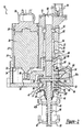
- FIG. 2 depicts a cross-sectional view of the EGR valve 10 in accordance with the teachings of the present invention.
- the EGR valve 10 has an motor assembly 21 and a valve assembly 22.
- the motor assembly 21 has a housing 24 designed to accept an electrical connector 26.
- An elastomeric seal 28 is used to seal the connector 26 to the housing 24.
- a motor 30 is contained inside of the housing 24 and serves to actuate the valve assembly 22.
- a retaining plate 32 and screws 34 are used to connect motor 30 to the housing 24.
- Motor 30 is connected to electrical connector 26 which provides a source of power to actuate the motor 30.
- Valve assembly 22 has a valve housing 36 that is connectable to the housing 24 of the motor assembly 21.
- the valve assembly 22 has a first valve member 38 and a second valve member 40 for selectively exhausting gas from the input passage 12 to the output passage 14.
- the first and second valve members 38, 40 each have a valve seat 42, 42a that define the opening between the input passage 12 and the output passage 14.
- the input passage 12 connects to the exhaust port from the engine.
- the output passage 14 connects to the air intake manifold which presents air to the engine for combustion.
- the first valve member 38 and the second valve member 40 are connected to a shaft 44 and move axially between open, closed or intermediate positions in response to the upward or downward movement of the shaft 44.
- the first and second valve members 38, 40 are in the closed position when they are seated against the valve seats 42, 42a, and are in the open position when they are unseated from the valve seats 42, 42a.
- the amount of exhaust gas moving from the input passage 12 to the output passage 14 will be the sum of the amount of gas moving past the first and second valve members 38, 40.
- the shaft 44 is disposed through a valve bushing 46 which will guide the shaft 44 as it moves longitudinally between the valve open and closed positions.
- an actuator assembly 47 is disposed inside of the valve housing 36.
- the actuator assembly 47 includes an engagement member such as a pin 48 which extends from the valve shaft 44 and rides along a ramped slot formed in the valve housing 36. It is also possible for the pin 48 to be perpendicularly disposed through an engagement hole 49 extending through the top portion of the shaft 44.
- One end of the pin 48 has a first roller bearing 50a disposed thereon and a second end of the pin 48 has a second roller bearing 50 disposed thereon.
- the first roller bearing 50a is slidably disposed in a first slot 53 and the second roller bearing 50 is disposed in a second slot 55, which are positioned 180° from one another.
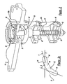
- the first slot 53 and the second slot 55 each include a lower ramp surface 52 and an upper ramp surface 54 that guide the rotational and longitudinal movement of the shaft 44 as shown in Figure 3a.
- the use of roller bearings 50, 50a on lower and upper ramp surfaces 52, 54 allows the shaft 44 to rotate upwardly and downwardly between the valve open and closed positions.
- slots 53, 55 are shown engaging bearings 50 and 50a on opposite sides of the pin 48, a single pin and bearing and a single slot is also within the scope of the present invention.
- two slots 53, 55 are provided for engaging both sides of the pin 48. However, more than two slots can be utilized if desired.
- roller bearings 50, 50a on lower and upper ramp surfaces 52, 54 allows the shaft 44 to rotate upwardly and downwardly between the valve open, closed and intermediate positions.
- the degree of incline of the lower ramp surface 52 and upper ramp surface 54 determines the rate at which the valve members 38, 40 move axially compared with the rotational movements.
- the degree of incline of the lower ramp surface 52 and upper ramp surface 54 can vary between zero degrees to eighty degrees. In a preferred embodiment as shown in Figure 3a the slope is progressive from the fully closed to the fully opened position.
- the beginning angle of the ramp 'a' is generally from about 0 to about 20 degrees and preferably from about 0 to 10 degrees. This allows greater force for moving the valve away from the valve seat.
- the ramp increases in slope to an angle 'b' at the fully open position for providing more rapid opening of the valve toward the end of rotation of the valve shaft.
- the angle 'b' is generally from about 10 to about 80 degrees, typically from about 10 to about 60 degrees and preferably from about 20 to about 30 degrees.
- the length of the slots may vary depending on the application such that the rotation of the valve shaft 44 is dependant on the length of the slot.
- the range of rotation is from about 45 degrees to about 120 degrees.
- the rotation of the shaft is 90 degrees the length of travel.
- greater rotational travel such as one to three or more rotations can be employed if desireable in a particular application.
- roller bearings 50, 50a on the ends of pin 48 reduces frictional loss that would occur between pin 48 and the surface of the lower ramp surface 52 and upper ramp surface 54. While this particular embodiment uses roller bearings 50, 50a to reduce friction loss, it should be understood that it is not always necessary to incorporate roller bearings 50, 50a in every application of this invention. For example, it is within the scope of the invention to have an embodiment that has no roller bearings 50, 50a.
- the force for providing movement of the shaft 44 is supplied by a series of gears which are connected to the motor 30 of the actuator assembly 21.
- a motor shaft 56 protrudes from the motor 30 into the valve housing 24.
- the motor shaft 56 is configured to rotate bi-directionally about the longitudinal axis of motor shaft 56.
- a first gear 58 is connected to the motor shaft 56 and is configured to rotate in the same direction as the motor shaft 56.
- a second gear 60 is engageable with the first gear 58 and will rotate in the opposite direction of the motor shaft 56 and the first gear 58.
- the second gear 60 is connected to the pin 48 by way of a yoke portion 57 which has a slot for engaging the pin 48 in a rotational direction but allowing the pin to move in an axial direction in the slot. This rotates the pin 48 to along lower ramp surfacec 52 and upper ramp surface 54 in response to the rotation of the second gear 60.
- Suitable motors for use in the present invention include brushed or brushless D.C. motors, stepper motors, torque motors, variable reluctance motors, pneumatic, hydraulic motors, and rotational solenoid and while not preferred an AC motor could be used or a linear solenoid actuator. While a gearing arrangement is shown for translating rotational movement from the motor to the valve shaft other methods of rotating the shaft can be utilized in the present invention. For instance the shaft could be directly rotated by the motor or the motor could be connected by way of a chain or belt drive or a rack and pinion arrangement. Additionally, the motor can be connected by way of a four bar link mechanism for rotating the shaft with a lever.
- a bore 62 extends longitudinally inside of the valve housing 36.
- the bore 62 has a first end 68 and a second end 70 located distally from the first end 68.
- the bore 62 further includes an upper region 64 that is defined at a first end 72 by the first end 68 and a lower region 66 that is defined at a second end 74 and by the second end 70 of the bore 62.
- the second gear 60 extends across the bore 62 and defines a second end 76 of the upper region 64 or the bore 62 and the first end 78 of the lower region 66 of the bore 62.
- the second gear 60 further includes a gear opening 80 for receiving a guide shaft 82.
- the guide shaft 82 functions to hold the second gear 60 in place against the pin 48 during the rotation of the second gear 60.
- the guide shaft 82 extends from the gear opening 80 toward the first end 68 of the bore 62.
- a torsion spring 84 is placed over the guide shaft 82 between the second gear 60 and a spring bushing 86.
- the roller bearings 88 are positioned between the guide shaft 82 and the side wall of the bore 62.
- a guide shaft bushing 90 is positioned between the guide shaft 82 and side wall of the bore 62 near the end of the guide shaft 82 and functions to hold the guide shaft 82 in place during rotation.
- a washer end clip 92 rotatably secures the end of guide shaft 82 to the side wall of bore 62.
- Torsion spring provides a fail-safe return to closed position if the motor fails.
- a position sensor 94 is affixed to the first end 68 of the bore 62.
- the position sensor 94 and the guide shaft 82 have interconnecting design features that will allow the position sensor 94 to provide an output signal based upon the degree of movement of the guide shaft 82.
- the position sensor 94 contains terminals for electrical connection to a suitable controller (not shown).
- Figure 3 is a partially broken away perspective view of the EGR valve 10 illustrating the EGR valve 10 in the closed position.
- One end of the pin 48 is slidably disposed on the lower ramp surface 52, while the second end of pin 48 is slidably disposed on the upper ramp surface 54.
- the roller bearings 88 are placed above and below the ends of pin 48.
- the bearings 88 allow the ends of pin 48 to slide along the lower and upper ramp surfaces 52, 54.
- the rollers will be configured to roller bearings 88 on the lower and upper ramp surfaces 52, 54.
- Figure 4 is a partially broken away perspective view of the EGR valve 10 illustrating the EGR valve 10 in the open position.
- second gear (not shown) rotates
- the shaft 44 will also rotate so that the ends of pin 48 slide along lower and upper ramp surfaces 52, 54.
- the first and second valve members 38, 40 will move downward away from the valve seats 42, 42a to allow exhaust from the output 16 of the engine to move to the input passage 18 of the engine.
- a valve spring 96 is disposed on the valve shaft 44 between the second valve member 40 and the first valve member 38.
- the second valve member 40 When the second valve member 40 is moved from the open position to the closed position the second valve member 40 contacts the second valve seat 42a and slides along the valve shaft 44 toward the first valve member 38 while the valve shaft 44 moves in the opposite direction toward the actuator assembly 47.
- the first valve member 38 is fixed to the end of the valve shaft 44 and does not slide. As the first valve member 38 moves toward the second valve member 40, which is now stationary since it is abutted against the second valve seat 42a, the first valve 38 member contacts the valve spring 96 and begins to slide the valve spring 96 upward toward the second valve member 40.
- valve spring then abuts against and compresses against the second valve member 40 as the valve spring 96 becomes compressed between the first valve member and the second valve member 40.
- the first valve member 38 will finish compressing the valve spring 96 when the first valve member 38 is seated on the first valve seat 42.
- first and second valve members 38, 40 The rotational movement of first and second valve members 38, 40 between the open and closed position causes the first and second valve members 38, 40 rotate against the valve seats 42, 42a. This functions to clean the first valve member 38 and second valve member 40 by rubbing off residue on the valve member 38, 40 and the valve seats 42, 42a.
Landscapes
- Engineering & Computer Science (AREA)
- Chemical & Material Sciences (AREA)
- Combustion & Propulsion (AREA)
- Mechanical Engineering (AREA)
- General Engineering & Computer Science (AREA)
- Exhaust-Gas Circulating Devices (AREA)
- Lift Valve (AREA)
- Electrically Driven Valve-Operating Means (AREA)
- Mechanically-Actuated Valves (AREA)
Abstract
Description
Claims (12)
- A vehicle gaseous fluid metering valve (10) comprising:a valve housing (36), said valve housing (36) being adapted for routing of exhaust gas from an input passage (12) to an output passage (14);a valving assembly (22) positioned inside said valve housing (36) for selectively exhausting gas from said input passage (12) to said output passage (14), said valving assembly (22) including at least one valve seat (42) acting as an opening between said input passage (12) and said output passage (14), and at least one valve member (38) operative with said valve seat (42) and acting as a moveable barrier between said input passage (12) and said output passage (14);a valve shaft (44) connected to said at least one valve member, said valve shaft (44) is operable for moving said at least one valve member (38) in response to rotation of said valve shaft (44); andan actuator (47) operable for rotating said valve shaft (44) for causing corresponding axial movement of said at least one valve member (38).
- The vehicle gaseous fluid metering valve (10) of claim 1, wherein said actuator (47) further comprises:an engagement member (48) extending from said valve shaft (44); anda first ramped surface (53) formed inside of said valve housing (36), wherein said member (48) engages said first ramped surface (53) during rotation of said valve shaft (44) for moving said shaft (44) in an axial direction in response to rotation of said valve shaft (44).
- The vehicle gaseous fluid metering valve (10) of claim 2 wherein said member is a pin extending from the valve shaft (44) and said ramp portion is a first slot (53) formed in a wall of the valve housing (36).
- The vehicle gaseous fluid metering valve (10) of claim 3 further comprising a first roller bearing (50a) disposed on a first end of said pin (48), wherein said first bearing engages (50a) said first slot (53) for riding along the first slot (53) during rotation of the valve shaft (44).
- The vehicle gaseous fluid metering valve (10) of claim 3 or 4 wherein said first slot (53) is progressively angled from a first angle (a) at a valve seat breaking end of said slot to a second angle (b) at a valve open end of said slot.
- The vehicle gaseous fluid metering valve (10) of claim 3 or 4 wherein the rate of axial movement of said valve shaft (44) between said open position and said closed position is a function of the degree of incline of said first slot (53).
- The vehicle gaseous fluid metering valve (10) of any one of claims 1 to 6 wherein said valving assembly (22) includes a second connected valve member (40) for seating on a second valve seat (42a).
- The vehicle gaseous fluid metering valve (10) of claim 7, further comprising:a lost motion device (96) for allowing one of said first valve member (38) or said second valve member (40) to reach a valve seat prior to the other of said valve member yet allowing the other of the valve member to close.
- The vehicle gaseous fluid metering valve (10) of any one of claims 3 to 6, wherein said actuator (47) further comprises:a second slot (55) formed inside of said valve housing (36), wherein said second slot (55) has a lower ramp surface (52) and an upper ramp surface (54), wherein said pin (48) extends laterally through said valve shaft (44), wherein a first end of said pin (48) is slidably engaged in said first slot (53) and a second end of said pin (48) is slidably engaged in said second slot (55).
- The vehicle gaseous fluid metering valve (10) of any one of claims 1 to 9, wherein said at least one valve member (38) rotates against said at least one valve seat (42) to self-clean said at least one valve member (38) and said at least one valve seat (42) prior to opening of said valve assembly (22).
- The vehicle gaseous fluid metering valve (10) of claim 10 wherein any fluid or substance on said at least one valve seat (42) and said at least one valve member (38) is sheared during the rotation of said at least one valve member (42).
- A method of operating a vehicle gaseous fluid metering valve (10) comprising the steps of:providing a valve housing (36) positioned between an input passage (12) and an output passage (14);providing a valve assembly (22) having at least one valve seat (42) and at least one valve member (38);providing a valve shaft (44);providing a valve shaft (44) configured to move in an axial direction in response to rotation about its axis, said valve shaft (44) coupled to said at least one valve member (38) for moving of the at least one valve member (38) in response to rotation of the shaft (44); andproviding an actuator (47) for rotating the valve shaft (44) for moving the valve member (38) in an axial direction in response to rotation of the valve shaft (44) and rotating the valve shaft (44) to provide corresponding axial movement of the valve member (38).
Applications Claiming Priority (2)
| Application Number | Priority Date | Filing Date | Title |
|---|---|---|---|
| US39345902P | 2002-07-02 | 2002-07-02 | |
| US393459P | 2002-07-02 |
Publications (3)
| Publication Number | Publication Date |
|---|---|
| EP1378655A2 true EP1378655A2 (en) | 2004-01-07 |
| EP1378655A3 EP1378655A3 (en) | 2006-08-02 |
| EP1378655B1 EP1378655B1 (en) | 2010-11-03 |
Family
ID=29720449
Family Applications (1)
| Application Number | Title | Priority Date | Filing Date |
|---|---|---|---|
| EP20030254213 Expired - Lifetime EP1378655B1 (en) | 2002-07-02 | 2003-07-02 | Gaseous fluid metering valve |
Country Status (3)
| Country | Link |
|---|---|
| US (2) | US7086636B2 (en) |
| EP (1) | EP1378655B1 (en) |
| DE (1) | DE60334758D1 (en) |
Cited By (9)
| Publication number | Priority date | Publication date | Assignee | Title |
|---|---|---|---|---|
| EP1793114A2 (en) | 2005-12-02 | 2007-06-06 | Behr Thermot-tronik GmbH | Apparatus, in particular exhaust gas recirculation valve device, for controlling a fluid flow |
| WO2009092422A1 (en) | 2008-01-22 | 2009-07-30 | Bayerische Motoren Werke Aktiengesellschaft | Valve unit for an exhaust gas recirculation unit |
| WO2011061051A1 (en) | 2009-11-19 | 2011-05-26 | Pierbrug Gmbh | Positioning device for converting a rotary motion into a linear motion |
| DE102010014841A1 (en) * | 2010-04-13 | 2011-10-13 | Pierburg Gmbh | Arrangement of a valve in a bore of a channel housing |
| CN102483015A (en) * | 2009-06-17 | 2012-05-30 | 法雷奥电机控制系统公司 | Motion conversion device and valve comprising such device |
| WO2017060022A1 (en) * | 2015-10-05 | 2017-04-13 | Pierburg Gmbh | Valve for an internal combustion engine |
| FR3045108A1 (en) * | 2015-12-10 | 2017-06-16 | Peugeot Citroen Automobiles Sa | ASSEMBLY OF SELF-CLEANING VALVE AND ITS ACTUATION DEVICE |
| DE102007017658B4 (en) | 2006-04-12 | 2018-12-13 | Mahle International Gmbh | Device for controlling / controlling an exhaust gas flow, heat exchanger, system |
| EP3633179A1 (en) * | 2018-10-01 | 2020-04-08 | Continental Automotive GmbH | Valve for controlling gas flow and system for exhaust gas recirculation to an internal combustion engine |
Families Citing this family (31)
| Publication number | Priority date | Publication date | Assignee | Title |
|---|---|---|---|---|
| US7011081B2 (en) * | 2004-02-24 | 2006-03-14 | Siemens Vdo Automotive Inc. | Double-pintle emission control valve having a one-piece double-seat element |
| TW200600709A (en) * | 2004-06-03 | 2006-01-01 | Applied Films Gmbh & Co Kg | Vacuum closure with linear drive unit |
| GB0419060D0 (en) * | 2004-08-27 | 2004-09-29 | Delphi Tech Inc | Valve actuating mechanism |
| KR101299523B1 (en) * | 2005-02-07 | 2013-08-23 | 보그워너 인코포레이티드 | Exhaust throttle-egr valve module for a diesel engine |
| KR20070108948A (en) | 2005-03-08 | 2007-11-13 | 보르그워너 인코퍼레이티드 | EBR valve with standby position |
| US20060288688A1 (en) * | 2005-06-22 | 2006-12-28 | Jean-Pierre Lair | Turbofan core thrust spoiler |
| EP2044353B1 (en) * | 2006-07-25 | 2011-01-26 | BorgWarner, Inc. | Control algorithm for a device |
| FR2914975B1 (en) * | 2007-04-16 | 2009-05-29 | Valeo Sys Controle Moteur Sas | DEVICE FOR TRANSFORMING A PIVOT MOTION OF A GEAR INTO A TRANSLATION MOVEMENT OF A SLIDER AND VALVE COMPRISING SUCH A DEVICE |
| US7762526B2 (en) * | 2007-08-27 | 2010-07-27 | Nor-Cal Products, Inc. | Pendulum valve having independently and rapidly controllable theta-and z-axis motion |
| KR20120050967A (en) * | 2009-06-17 | 2012-05-21 | 발레오 시스템므 드 꽁트롤르 모뙤르 | Valve comprising a movement transformation device |
| FR2947026B1 (en) * | 2009-06-17 | 2011-07-15 | Valeo Sys Controle Moteur Sas | MOVEMENT TRANSFORMATION DEVICE AND VALVE HAVING SUCH A DEVICE |
| CN101696667A (en) * | 2009-10-29 | 2010-04-21 | 奇瑞汽车股份有限公司 | EGR valve of engine |
| FR2959266B1 (en) * | 2010-04-27 | 2012-05-18 | Artus | QUICK OPEN FILLING DEVICE |
| EP2418373A1 (en) * | 2010-08-12 | 2012-02-15 | Cooper-Standard Automotive (Deutschland) GmbH | Actuator and waste gas reclaiming valve, wastegate or variable turbine geometry with an actuator |
| KR20120054410A (en) * | 2010-11-19 | 2012-05-30 | 주식회사 만도 | Electric waste gate actuator for turbochager |
| US9212760B2 (en) * | 2011-07-11 | 2015-12-15 | Jbt Products, Inc. | Rotary actuator interface and method |
| JP6031841B2 (en) * | 2012-06-14 | 2016-11-24 | いすゞ自動車株式会社 | Method for cleaning EGR valve of internal combustion engine and internal combustion engine |
| US9188058B2 (en) * | 2012-10-17 | 2015-11-17 | Ford Global Technologies, Llc | Method for controlling a turbocharger arrangement with an electric actuator and spring |
| FR3001786B1 (en) * | 2013-02-07 | 2016-03-04 | Valeo Sys Controle Moteur Sas | DISCHARGE VALVE AND DEVICE THEREFOR |
| EP2884086B1 (en) * | 2013-12-11 | 2017-12-20 | Borgwarner Inc. | Actuator with valve return |
| WO2016063194A2 (en) * | 2014-10-19 | 2016-04-28 | Padmini Vna Mechatronics Pvt. Ltd. | Self-cleaning poppet egr valve |
| JP6609168B2 (en) * | 2015-11-13 | 2019-11-20 | 株式会社Ihi | Valve actuator |
| US10113650B2 (en) * | 2016-01-12 | 2018-10-30 | Engip, LLC | Dual seat valve |
| KR101926681B1 (en) * | 2017-01-02 | 2018-12-11 | 주식회사 코렌스 | Valve assembly with improved cylindrical-cam operation |
| US10473232B2 (en) | 2017-01-13 | 2019-11-12 | Borgwarner Inc. | Split linkage mechanism for valve assembly |
| US10871210B2 (en) * | 2018-02-21 | 2020-12-22 | Borgwarner Inc. | Gear drive assembly for actuator system |
| US11118630B2 (en) * | 2019-02-08 | 2021-09-14 | Caterpillar Inc. | Adapter for a valve system |
| EP3765772B1 (en) * | 2019-05-17 | 2026-03-18 | MacDuff, Malcolm | Quarter-turn pin-valve actuator |
| EP4567313A1 (en) * | 2023-12-06 | 2025-06-11 | Tatsuno Corporation | Flow rate regulating valve |
| JP7799957B2 (en) * | 2023-12-06 | 2026-01-16 | 株式会社タツノ | Flow Control Valve |
| CN118208344B (en) * | 2024-04-30 | 2024-09-10 | 山东泰展机电科技股份有限公司 | EGR valve for automobile |
Family Cites Families (74)
| Publication number | Priority date | Publication date | Assignee | Title |
|---|---|---|---|---|
| US466124A (en) * | 1891-12-29 | Puzzle | ||
| US66427A (en) * | 1867-07-02 | Improvement in cider-mills | ||
| US616275A (en) * | 1898-12-20 | Reciprocating valve | ||
| US245662A (en) * | 1881-08-16 | Ijvlvlfsljdtj | ||
| US198135A (en) * | 1877-12-11 | Improvement in barbed wire fences | ||
| US1640040A (en) * | 1922-02-13 | 1927-08-23 | Kelly Valve Company | Self-grinding valve |
| US1575449A (en) * | 1923-07-12 | 1926-03-02 | Scon L Mozian | Valve |
| US1679898A (en) * | 1924-04-12 | 1928-08-07 | Israel B Gilbert | Check valve |
| US1711593A (en) * | 1926-10-21 | 1929-05-07 | Israel B Gilbert | Regrinding valve |
| US1987135A (en) * | 1933-07-24 | 1935-01-08 | Sugden Albert | Valve |
| US2615465A (en) * | 1949-03-21 | 1952-10-28 | Woodward Erwin | Self-cleaning valve |
| US3071149A (en) * | 1959-12-03 | 1963-01-01 | Aluminum Co Of America | Mechanical cleaning valve construction |
| GB1001629A (en) * | 1963-03-18 | 1965-08-18 | Rotork Eng Co Ltd | Improvements in or relating to actuating mechanisms, more particularly for fluid flow control valves |
| US3727631A (en) * | 1971-09-20 | 1973-04-17 | T Suzuki | Valve for pressure indicators |
| US4195816A (en) * | 1977-04-15 | 1980-04-01 | Bettis Corporation | Valve actuator |
| US4177825A (en) * | 1977-12-05 | 1979-12-11 | Kaiser Aluminum & Chemical Corporation | Self-grinding valve mechanism |
| US4666124A (en) * | 1986-04-29 | 1987-05-19 | Johnston Pump/General Valve, Inc. | Valve operator for a plug-type valve |
| JP3050690B2 (en) * | 1992-03-09 | 2000-06-12 | 株式会社デンソー | Electromagnetic drive control valve |
| FR2695683B1 (en) * | 1992-09-15 | 1994-12-02 | Sagem Allumage | Control assembly for an exhaust gas recirculation valve of an internal combustion engine. |
| US5511531A (en) * | 1994-05-19 | 1996-04-30 | Siemens Electric Ltd. | EGR valve with force balanced pintle |
| FR2724976B1 (en) | 1994-09-27 | 1996-12-20 | Sagem Allumage | RECYCLED EXHAUST GAS QUANTITY UNIT IN AN EXHAUST GAS RECIRCULATION SYSTEM OF AN INTERNAL COMBUSTION ENGINE |
| FR2727158B1 (en) | 1994-11-17 | 1996-12-27 | Sagem Allumage | VALVE FOR CONTROLLING THE QUANTITY OF RECYCLED EXHAUST GAS IN AN INTERNAL COMBUSTION ENGINE |
| FR2727156B1 (en) | 1994-11-17 | 1996-12-27 | Sagem Allumage | CUT-OFF VALVE FOR AIR INJECTION CIRCUIT TO EXHAUST OF INTERNAL COMBUSTION ENGINE |
| US5979866A (en) * | 1995-06-06 | 1999-11-09 | Sagem, Inc. | Electromagnetically actuated disc-type valve |
| US5593132A (en) * | 1995-06-30 | 1997-01-14 | Siemens Electric Limited | Electromagnetic actuator arrangement for engine control valve |
| US5911401A (en) * | 1995-08-29 | 1999-06-15 | Siemens Electric Limited | Electric actuated exhaust gas recirculation valve |
| DE69606418T2 (en) * | 1995-08-29 | 2009-11-26 | Siemens Canada Ltd., Mississauga | EXHAUST GAS VALVE WITH VALVE SHAFT |
| US5704585A (en) * | 1995-08-29 | 1998-01-06 | Siemens Electric Limited | Electrical connection between closure cap and internal actuator of an electrically actuated valve |
| US5588414A (en) * | 1995-08-29 | 1996-12-31 | Siemens Electric Limited | Construction for maintaining assembled axial integrity of an electrically actuated valve |
| FR2748780B1 (en) | 1996-05-14 | 1998-08-14 | Sagem Allumage | VALVE FOR INTERNAL COMBUSTION ENGINE EXHAUST GAS RECIRCULATION SYSTEM |
| US5960776A (en) * | 1996-11-21 | 1999-10-05 | Siemens Canada Limited | Exhaust gas recirculation valve having a centered solenoid assembly and floating valve mechanism |
| US5669364A (en) * | 1996-11-21 | 1997-09-23 | Siemens Electric Limited | Exhaust gas recirculation valve installation for a molded intake manifold |
| US5996559A (en) * | 1997-07-08 | 1999-12-07 | Siemens Canada Limited | Integrated manifold and purge valve |
| US6223733B1 (en) * | 1997-07-08 | 2001-05-01 | Siemens Canada Limited | Exhaust gas recirculation valve |
| US6152115A (en) * | 1997-07-08 | 2000-11-28 | Siemens Canada Limited | Integrated engine intake manifold having a fuel vapor purge valve and an exhaust gas recirculation valve |
| US6073617A (en) * | 1997-07-08 | 2000-06-13 | Siemens Canada Ltd. | Manifold-mounted emission control valve |
| US5957117A (en) * | 1997-08-07 | 1999-09-28 | Siemens Canada Limited | Automotive emission control valve assembly |
| DE19735046A1 (en) * | 1997-08-13 | 1999-04-22 | Pierburg Ag | Arrangement of a spring clip |
| US5947092A (en) * | 1997-09-03 | 1999-09-07 | Siemens Canada Limited | Space-efficient electromagnetic actuated exhaust gas recirculation valve |
| US5924675A (en) * | 1997-09-03 | 1999-07-20 | Siemens Canada Limited | Automotive emission control valve having two-part solenoid pole piece |
| US5950605A (en) * | 1997-09-03 | 1999-09-14 | Siemens Canada Ltd. | Automotive emission control valve having opposing pressure forces acting on the valve member |
| US5901690A (en) * | 1997-09-03 | 1999-05-11 | Siemens Canada Limited | Electromagnetic actuated exhaust gas recirculation valve |
| FR2772429B1 (en) | 1997-12-16 | 2000-06-02 | Sagem | CONTROL VALVE FOR AN EXHAUST GAS RECIRCULATION SYSTEM OF AN INTERNAL COMBUSTION ENGINE |
| FR2773847B1 (en) | 1998-01-19 | 2000-03-24 | Sagem | INJECTION SYSTEM RICHNESS ESTIMATING DEVICE FOR INTERNAL COMBUSTION ENGINE |
| JP3929505B2 (en) * | 1998-02-27 | 2007-06-13 | 三菱電機株式会社 | Exhaust gas recirculation device |
| US6170476B1 (en) * | 1998-05-26 | 2001-01-09 | Siemens Canada Ltd. | Internal sensing passage in an exhaust gas recirculation module |
| US6138652A (en) * | 1998-05-26 | 2000-10-31 | Siemens Canada Limited | Method of making an automotive emission control module having fluid-power-operated actuator, fluid pressure regulator valve, and sensor |
| US6116224A (en) * | 1998-05-26 | 2000-09-12 | Siemens Canada Ltd. | Automotive vehicle having a novel exhaust gas recirculation module |
| US6189520B1 (en) * | 1998-05-26 | 2001-02-20 | Siemens Canada Limited | Integration of sensor, actuator, and regulator valve in an emission control module |
| US6006732A (en) * | 1998-09-03 | 1999-12-28 | Navistar International Transportation Corp | Balanced flow EGR control apparatus |
| US6397079B1 (en) * | 1998-09-16 | 2002-05-28 | Intel Corporation | Augmenting the capabilities of transceivers |
| FR2784712B1 (en) * | 1998-10-15 | 2001-09-14 | Sagem | ELECTROMAGNETIC VALVE OPERATION METHOD AND DEVICE |
| FR2792679B1 (en) * | 1999-04-23 | 2001-07-27 | Sagem | ADJUSTABLE VALVE CONTROL DEVICE AND METHOD FOR ADJUSTING SUCH A DEVICE |
| US6247461B1 (en) * | 1999-04-23 | 2001-06-19 | Delphi Technologies, Inc. | High flow gas force balanced EGR valve |
| US6109302A (en) * | 1999-04-23 | 2000-08-29 | Delphi Technologies, Inc. | Three-way gas management valve |
| US6217001B1 (en) * | 1999-06-29 | 2001-04-17 | Delphi Technologies, Inc. | Pressure balanced gas valve |
| US6213447B1 (en) * | 1999-07-29 | 2001-04-10 | Delphi Technologies, Inc. | Poppet value having a compliant shaft guide and compliant valve head |
| US6299130B1 (en) * | 1999-10-14 | 2001-10-09 | Siemens Canada Limited | EEGR valve with flexible bearing |
| US6295975B1 (en) * | 1999-10-14 | 2001-10-02 | Siemens Canada Limited | Double action single valve EEGR |
| US6378507B1 (en) * | 1999-10-20 | 2002-04-30 | Siemens Canada Limited | Exhaust gas recirculation valve having an angled seat |
| US6230742B1 (en) * | 1999-10-21 | 2001-05-15 | Delphi Technologies, Inc. | Poppet valve assembly apparatus having two simultaneously-seating heads |
| US6382151B2 (en) * | 2000-02-24 | 2002-05-07 | Delphi Technologies, Inc. | Ring gear variable valve train device |
| US6409145B1 (en) * | 2000-02-28 | 2002-06-25 | Delphi Technologies, Inc. | Plunger assembly having a preset spring force pre-load |
| US6311677B1 (en) * | 2000-03-30 | 2001-11-06 | Siemens Canada Limited | Engine mounting of an exhaust gas recirculation valve |
| US6390078B1 (en) * | 2000-04-18 | 2002-05-21 | Delphi Technologies, Inc. | Two stage concentric EGR valves |
| DE20018548U1 (en) * | 2000-10-30 | 2002-03-21 | CAMERON GmbH, 29227 Celle | Rotating regulating |
| FR2812684B1 (en) | 2000-08-01 | 2002-10-25 | Sagem | METHOD AND DEVICE FOR CONTROLLING THE OPENING OF A VALVE WITH ELECTROMAGNETIC ACTUATOR |
| US6390079B1 (en) * | 2000-08-21 | 2002-05-21 | Siemens Canada Limited | Exhaust gas recirculation valve including cam linkage for converting constant angular motion to non-linear motion |
| FR2816660B1 (en) | 2000-11-15 | 2003-05-02 | Sagem | METHOD AND DEVICE FOR CONTROLLING THE OPERATION OF A SELF-IGNITION INTERNAL COMBUSTION ENGINE |
| WO2002040902A2 (en) * | 2000-11-20 | 2002-05-23 | Siemens Vdo Automotive Corporation | Directly actuated engine valve |
| US6415777B1 (en) * | 2000-11-28 | 2002-07-09 | Siemens Automotive Inc. | EGR module having orifice in a pressure sensing port |
| FR2821645B1 (en) | 2001-03-01 | 2003-09-05 | Sagem | METHOD FOR TAKING ACCOUNT OF INCOMPLETE COMBUSTION IN A CYLINDER OF AN INTERNAL COMBUSTION ENGINE, AND DEVICE FOR CONTROLLING AN ENGINE USING THE SAME |
| FR2824380B1 (en) | 2001-05-03 | 2006-03-17 | Sagem | METHOD OF ELECTRONIC DECREASING OF A CONTROLLED VALVE ACCORDING TO THIS PROCESS |
| DE10209335A1 (en) * | 2002-03-02 | 2003-09-11 | Pierburg Gmbh | valve means |
-
2003
- 2003-07-02 US US10/612,329 patent/US7086636B2/en not_active Expired - Lifetime
- 2003-07-02 DE DE60334758T patent/DE60334758D1/en not_active Expired - Lifetime
- 2003-07-02 EP EP20030254213 patent/EP1378655B1/en not_active Expired - Lifetime
-
2006
- 2006-06-15 US US11/453,598 patent/US7487789B2/en not_active Expired - Fee Related
Cited By (14)
| Publication number | Priority date | Publication date | Assignee | Title |
|---|---|---|---|---|
| EP1793114A3 (en) * | 2005-12-02 | 2008-10-15 | Behr Thermot-tronik GmbH | Apparatus, in particular exhaust gas recirculation valve device, for controlling a fluid flow |
| EP1793114A2 (en) | 2005-12-02 | 2007-06-06 | Behr Thermot-tronik GmbH | Apparatus, in particular exhaust gas recirculation valve device, for controlling a fluid flow |
| DE102007017658B4 (en) | 2006-04-12 | 2018-12-13 | Mahle International Gmbh | Device for controlling / controlling an exhaust gas flow, heat exchanger, system |
| WO2009092422A1 (en) | 2008-01-22 | 2009-07-30 | Bayerische Motoren Werke Aktiengesellschaft | Valve unit for an exhaust gas recirculation unit |
| CN102483015A (en) * | 2009-06-17 | 2012-05-30 | 法雷奥电机控制系统公司 | Motion conversion device and valve comprising such device |
| CN102483015B (en) * | 2009-06-17 | 2014-01-15 | 法雷奥电机控制系统公司 | Movement transformation device and valve comprising such a device |
| WO2011061051A1 (en) | 2009-11-19 | 2011-05-26 | Pierbrug Gmbh | Positioning device for converting a rotary motion into a linear motion |
| DE102009053428A1 (en) | 2009-11-19 | 2011-06-09 | Pierburg Gmbh | Actuator for converting a rotary motion into a linear motion |
| DE102010014841A1 (en) * | 2010-04-13 | 2011-10-13 | Pierburg Gmbh | Arrangement of a valve in a bore of a channel housing |
| DE102010014841B4 (en) * | 2010-04-13 | 2014-10-23 | Pierburg Gmbh | Arrangement of a valve in a bore of a channel housing |
| EP2558751B1 (en) | 2010-04-13 | 2015-10-07 | Pierburg GmbH | Arrangement of a valve in a bore of a duct housing |
| WO2017060022A1 (en) * | 2015-10-05 | 2017-04-13 | Pierburg Gmbh | Valve for an internal combustion engine |
| FR3045108A1 (en) * | 2015-12-10 | 2017-06-16 | Peugeot Citroen Automobiles Sa | ASSEMBLY OF SELF-CLEANING VALVE AND ITS ACTUATION DEVICE |
| EP3633179A1 (en) * | 2018-10-01 | 2020-04-08 | Continental Automotive GmbH | Valve for controlling gas flow and system for exhaust gas recirculation to an internal combustion engine |
Also Published As
| Publication number | Publication date |
|---|---|
| US20060237675A1 (en) | 2006-10-26 |
| EP1378655B1 (en) | 2010-11-03 |
| US20040069285A1 (en) | 2004-04-15 |
| EP1378655A3 (en) | 2006-08-02 |
| US7086636B2 (en) | 2006-08-08 |
| DE60334758D1 (en) | 2010-12-16 |
| US7487789B2 (en) | 2009-02-10 |
Similar Documents
| Publication | Publication Date | Title |
|---|---|---|
| US7086636B2 (en) | Gaseous fluid metering valve | |
| EP1869308B1 (en) | Egr valve having rest position | |
| US7213613B2 (en) | High-flow dual poppet valve having equalized closing forces | |
| EP1103715B1 (en) | Exhaust gas re-circulation device for an internal combustion engine | |
| EP0887540B1 (en) | Exhaust gas recirculation valve | |
| KR101475810B1 (en) | Actuating Drive for Bidirectional Actuator | |
| US6494041B1 (en) | Total pressure exhaust gas recirculation duct | |
| US8065992B2 (en) | Valve arrangement for an exhaust gas recirculation device | |
| US20070001136A1 (en) | Exhaust gas recirculation valve having a rotary motor | |
| KR20150068287A (en) | ACTUATOR WIth Valve Return | |
| EP1664518A1 (en) | Valve | |
| US7204240B2 (en) | Integrated valve | |
| CA2407720C (en) | Egr valve apparatus | |
| EP1859157B1 (en) | Egr valve in internal combustion engines actuated by electric motor with rack and pinion | |
| KR101655129B1 (en) | Exhaust gas recirculation valve | |
| EP1632674A2 (en) | "Valve actuating mechanism" | |
| US20030047167A1 (en) | Tandem valve type throttle body | |
| KR20240084898A (en) | Spring Slide Abrasion Prevention type 3 Way EGR Valve Unit EGR(and Exhaust Gas Recirculation System thereby | |
| US12158126B2 (en) | Engine system | |
| US20260028951A1 (en) | Engine system | |
| JP2002256983A (en) | Exhaust gas recirculation device |
Legal Events
| Date | Code | Title | Description |
|---|---|---|---|
| PUAI | Public reference made under article 153(3) epc to a published international application that has entered the european phase |
Free format text: ORIGINAL CODE: 0009012 |
|
| AK | Designated contracting states |
Kind code of ref document: A2 Designated state(s): AT BE BG CH CY CZ DE DK EE ES FI FR GB GR HU IE IT LI LU MC NL PT RO SE SI SK TR |
|
| AX | Request for extension of the european patent |
Extension state: AL LT LV MK |
|
| 17P | Request for examination filed |
Effective date: 20040212 |
|
| RAP1 | Party data changed (applicant data changed or rights of an application transferred) |
Owner name: BORGWARNER INC. |
|
| PUAL | Search report despatched |
Free format text: ORIGINAL CODE: 0009013 |
|
| AK | Designated contracting states |
Kind code of ref document: A3 Designated state(s): AT BE BG CH CY CZ DE DK EE ES FI FR GB GR HU IE IT LI LU MC NL PT RO SE SI SK TR |
|
| AX | Request for extension of the european patent |
Extension state: AL LT LV MK |
|
| 17Q | First examination report despatched |
Effective date: 20061005 |
|
| AKX | Designation fees paid |
Designated state(s): DE FR GB |
|
| GRAP | Despatch of communication of intention to grant a patent |
Free format text: ORIGINAL CODE: EPIDOSNIGR1 |
|
| GRAS | Grant fee paid |
Free format text: ORIGINAL CODE: EPIDOSNIGR3 |
|
| GRAA | (expected) grant |
Free format text: ORIGINAL CODE: 0009210 |
|
| AK | Designated contracting states |
Kind code of ref document: B1 Designated state(s): DE FR GB |
|
| REG | Reference to a national code |
Ref country code: GB Ref legal event code: FG4D |
|
| REF | Corresponds to: |
Ref document number: 60334758 Country of ref document: DE Date of ref document: 20101216 Kind code of ref document: P |
|
| PLBE | No opposition filed within time limit |
Free format text: ORIGINAL CODE: 0009261 |
|
| STAA | Information on the status of an ep patent application or granted ep patent |
Free format text: STATUS: NO OPPOSITION FILED WITHIN TIME LIMIT |
|
| 26N | No opposition filed |
Effective date: 20110804 |
|
| REG | Reference to a national code |
Ref country code: DE Ref legal event code: R097 Ref document number: 60334758 Country of ref document: DE Effective date: 20110804 |
|
| REG | Reference to a national code |
Ref country code: FR Ref legal event code: PLFP Year of fee payment: 13 |
|
| PGFP | Annual fee paid to national office [announced via postgrant information from national office to epo] |
Ref country code: GB Payment date: 20150624 Year of fee payment: 13 |
|
| PGFP | Annual fee paid to national office [announced via postgrant information from national office to epo] |
Ref country code: FR Payment date: 20150624 Year of fee payment: 13 |
|
| GBPC | Gb: european patent ceased through non-payment of renewal fee |
Effective date: 20160702 |
|
| PG25 | Lapsed in a contracting state [announced via postgrant information from national office to epo] |
Ref country code: FR Free format text: LAPSE BECAUSE OF NON-PAYMENT OF DUE FEES Effective date: 20160801 |
|
| REG | Reference to a national code |
Ref country code: FR Ref legal event code: ST Effective date: 20170331 |
|
| PG25 | Lapsed in a contracting state [announced via postgrant information from national office to epo] |
Ref country code: GB Free format text: LAPSE BECAUSE OF NON-PAYMENT OF DUE FEES Effective date: 20160702 |
|
| PGFP | Annual fee paid to national office [announced via postgrant information from national office to epo] |
Ref country code: DE Payment date: 20190617 Year of fee payment: 17 |
|
| REG | Reference to a national code |
Ref country code: DE Ref legal event code: R119 Ref document number: 60334758 Country of ref document: DE |
|
| PG25 | Lapsed in a contracting state [announced via postgrant information from national office to epo] |
Ref country code: DE Free format text: LAPSE BECAUSE OF NON-PAYMENT OF DUE FEES Effective date: 20210202 |