EP1378409A1 - Modular pedal - Google Patents
Modular pedal Download PDFInfo
- Publication number
- EP1378409A1 EP1378409A1 EP03380147A EP03380147A EP1378409A1 EP 1378409 A1 EP1378409 A1 EP 1378409A1 EP 03380147 A EP03380147 A EP 03380147A EP 03380147 A EP03380147 A EP 03380147A EP 1378409 A1 EP1378409 A1 EP 1378409A1
- Authority
- EP
- European Patent Office
- Prior art keywords
- support part
- housing
- modular
- pedal body
- pedal
- Prior art date
- Legal status (The legal status is an assumption and is not a legal conclusion. Google has not performed a legal analysis and makes no representation as to the accuracy of the status listed.)
- Granted
Links
Images


Classifications
-
- G—PHYSICS
- G05—CONTROLLING; REGULATING
- G05G—CONTROL DEVICES OR SYSTEMS INSOFAR AS CHARACTERISED BY MECHANICAL FEATURES ONLY
- G05G1/00—Controlling members, e.g. knobs or handles; Assemblies or arrangements thereof; Indicating position of controlling members
- G05G1/30—Controlling members actuated by foot
- G05G1/50—Manufacturing of pedals; Pedals characterised by the material used
- G05G1/506—Controlling members for foot-actuation
-
- B—PERFORMING OPERATIONS; TRANSPORTING
- B60—VEHICLES IN GENERAL
- B60T—VEHICLE BRAKE CONTROL SYSTEMS OR PARTS THEREOF; BRAKE CONTROL SYSTEMS OR PARTS THEREOF, IN GENERAL; ARRANGEMENT OF BRAKING ELEMENTS ON VEHICLES IN GENERAL; PORTABLE DEVICES FOR PREVENTING UNWANTED MOVEMENT OF VEHICLES; VEHICLE MODIFICATIONS TO FACILITATE COOLING OF BRAKES
- B60T7/00—Brake-action initiating means
- B60T7/02—Brake-action initiating means for personal initiation
- B60T7/04—Brake-action initiating means for personal initiation foot actuated
- B60T7/06—Disposition of pedal
-
- G—PHYSICS
- G05—CONTROLLING; REGULATING
- G05G—CONTROL DEVICES OR SYSTEMS INSOFAR AS CHARACTERISED BY MECHANICAL FEATURES ONLY
- G05G1/00—Controlling members, e.g. knobs or handles; Assemblies or arrangements thereof; Indicating position of controlling members
- G05G1/30—Controlling members actuated by foot
- G05G1/46—Means, e.g. links, for connecting the pedal to the controlled unit
Definitions
- the invention herein refers to pedals for vehicular use.
- Pedals for vehicles which comprise a pedal body which rotates around an axis of rotation, a socket which houses said axis of rotation, a shoe, and, if they are brake or clutch pedals, an additional part which houses the end of an actuator rod (a servo-brake or gear cylinder respectively), all the parts of said pedals being metallic and being welded together.
- pedals which are made entirely of plastic, are well-known, although said pedals are used for more minor functions, such as accelerator and clutch pedals, due to the mechanical properties of plastic.
- Pedals for vehicles in which the additional part for housing the end of said rod is not metallic, but, in general, is made of plastic, are also well-known.
- ES 2 020 932 B3 describes a pedal which comprises a pedal body and a part for housing the end of the actuator rod, such housing part including an additional part made of plastic which can be fitted elastically into the body of the pedal and also including an elastic device for holding the end of said rod.
- EP 0 896 162 A1 discloses a device for holding the end of the servo-brake rod for brake pedals.
- Said holding device comprises an additional detachable part, preferably made of plastic, which comprises elastic devices for holding the end of the rod.
- the object of the invention is to provide a modular pedal for vehicles as defined in the claims.
- the modular pedal of the invention comprises a pedal body that pivots around an axis of rotation, and a support part fixed to said pedal body, it being possible for said support part to be made of a material different from that of which the pedal body is made, and said material preferably being plastic.
- Said support part comprises a socket with a hole for the axis of rotation, producing a joint between the pedal body and said axis of rotation via said support part.
- the fact that the body of the pedal is not directly joined to the axis of rotation means that said pedal body can have a shape more suited to its function, thereby containing less material or, otherwise, the material used having some less-demanding mechanical characteristics.
- the body of the pedal is generally metallic and the material of the support part is preferably lighter, the pedal as a whole is lighter and cheaper.
- the simplicity of the assembly between pedal body and support part significantly reduces the cost of production.
- the pedal body comprises a housing into which the support part is inserted, said support part being joined to said pedal body via an elastic joint, preferably a detachable clip, to avoid welded joints, thus simplifying the assembly.
- the pedal body has a cross-section that is substantially U-shaped, the housing for the support part being delimited by said U-shape.
- the support part has side projections, and said pedal body has holes or supports into which said projections fit.
- the pedal body can comprise two side extensions that rest on part of the outer surface of the socket that has the hole for the axis of rotation.
- the support part can also comprise housing means in which the end of a rod can be fitted via which a driving force is transmitted to an actuator, principally to a servo-brake or clutch cylinder.
- the modular pedal comprises a pedal body 2 which pivots around an axis of rotation 3, and a support part 4 fixed to said pedal body 2, it being possible for said support part 4 to be made of a material different from that of which the pedal body is made 2, and said material preferably being plastic.
- Said support part 4, shown in detail in figures 3 and 4 comprises a socket 5 with a hole 6 for the axis of rotation 3, producing a joint between the pedal body 2 and said axis of rotation 3 via said support part 4.
- the pedal body 2 comprises a housing 7 into which the support part 4 is inserted, said support part 4 being joined to said pedal body 2 via an elastic joint, preferably a detachable clip.
- the pedal body 2 has a cross-section that is substantially U-shaped, the housing 7 being delimited by said U-shape.
- the support part 4 has side projections 8, and said pedal body 2 has holes or supports 9 into which said projections 8 fit.
- the pedal body 2 can comprise two side extensions 10 that rest on part of the outer surface of the socket 5 of the support part 4.
- the outer surface of the socket 5 is substantially cylindrical and the side projections 10 rest on approximately half of the outer perimeter of said socket 5.
- FIG. 6 shows how said assembly is carried out. Firstly, the socket 5 rests on the support part 4 on the side projections 10 of the pedal body 2, and the pedal body 2 is then inserted into the housing 7 turning it in direction 31.
- the support part 4 can also comprise housing means 11 in which the end 12 of a rod 13 is fitted via which a driving force is transmitted to an actuator, principally to a servo-brake or clutch cylinder.
- the housing means 11 comprise an elastic holding device 14 at the entrance of the housing means 11, and side walls 15, said elastic holding device 14 being joined to said side walls 15 and the side walls 15 being removable.
- Each side wall 15 has a support or clip 16 which holds said side wall 15 in its assembly position, and which transmits the force exerted by the end 12 of the actuator onto the holding device 14 to the whole of the support part 4.
- the end 12 of the rod 13 of the housing means 11 can be pulled out via the folding side walls 15, if necessary. To do this, the support part 4 only has to be pulled out from the housing 7 of the pedal body 2 and the side walls 15 removed.
- a jacket 30 may have to be inserted between the end 12 of the rod 13 and the housing means 11 of the support part 4.
- the end 12 of the rod 13 is spherical, with which said jacket 30 has an almost semi-spherical surface.
- the housing means 11 comprise a movable part 17 with a housing 18 in which approximately half of the end 12 of the rod 13 is fitted or, alternatively, the jacket 30, folding side housings 19 hingedly joined to the movable part 17, laminated side springs 20 joined to said folding housings 19, and a support surface 21 for the movable part 17.
- the end 12 of the rod 13 is substantially spherical, with which the housing 18 has a substantially semi-spherical internal surface and the folding housings 19 have an internal surface which is substantially a quarter of a sphere. Said folding housings 19 also have a groove 32 for holding the rod 13.
- the support part 4 also comprises folding side walls 22, each side wall 22 incorporating a flange 23, and the folding housings 19 have projections 24, said flanges 23 being shoed in the projections 24 when the end 13 of the rod 12 presses on the housing 11 and the movable part 17 presses on the surface 21.
- the side walls 22 have longitudinal guide bars 25 and the movable part 17 has longitudinal grooves 26 , said guide bars 25 being held in said grooves 26.
- the surface 21 of the support part 4 and the surface 27 of the movable part 17 are cylindrical.
- the modular pedal comprises a shoe 28 and an intermediate part 29 between said shoe 28 and the pedal body 2, said intermediate part 29 may be made of a different material from that of which the pedal body 2 is made, and said material preferably being plastic. Said intermediate part 29 is joined elastically to the pedal body 2, preferably via a detachable clip.
- the pedal body 2 adopts a straighter shape, so that it undergoes less force and can therefore contain less material or, otherwise, a material with less-demanding characteristics, which makes pedal 1 lighter and/or cheaper.
- the use of said intermediate part 29 allows the optimum position of the shoe 28 to be obtained with a simpler and sturdier geometry for the pedal body 2, now that said pedal body 2 can be less curved.
- the shoe 28 and the intermediate part 29 can be embodied in a single integral part.
Abstract
Description
- The invention herein refers to pedals for vehicular use.
- Pedals for vehicles are well-known which comprise a pedal body which rotates around an axis of rotation, a socket which houses said axis of rotation, a shoe, and, if they are brake or clutch pedals, an additional part which houses the end of an actuator rod (a servo-brake or gear cylinder respectively), all the parts of said pedals being metallic and being welded together.
- Likewise, pedals, which are made entirely of plastic, are well-known, although said pedals are used for more minor functions, such as accelerator and clutch pedals, due to the mechanical properties of plastic.
- Pedals for vehicles in which the additional part for housing the end of said rod is not metallic, but, in general, is made of plastic, are also well-known.
- ES 2 020 932 B3 describes a pedal which comprises a pedal body and a part for housing the end of the actuator rod, such housing part including an additional part made of plastic which can be fitted elastically into the body of the pedal and also including an elastic device for holding the end of said rod.
- EP 0 896 162 A1 discloses a device for holding the end of the servo-brake rod for brake pedals. Said holding device comprises an additional detachable part, preferably made of plastic, which comprises elastic devices for holding the end of the rod.
- The object of the invention is to provide a modular pedal for vehicles as defined in the claims.
- The modular pedal of the invention comprises a pedal body that pivots around an axis of rotation, and a support part fixed to said pedal body, it being possible for said support part to be made of a material different from that of which the pedal body is made, and said material preferably being plastic. Said support part comprises a socket with a hole for the axis of rotation, producing a joint between the pedal body and said axis of rotation via said support part.
- The fact that the body of the pedal is not directly joined to the axis of rotation means that said pedal body can have a shape more suited to its function, thereby containing less material or, otherwise, the material used having some less-demanding mechanical characteristics. In this way, given that the body of the pedal is generally metallic and the material of the support part is preferably lighter, the pedal as a whole is lighter and cheaper. In addition, the simplicity of the assembly between pedal body and support part significantly reduces the cost of production.
- The pedal body comprises a housing into which the support part is inserted, said support part being joined to said pedal body via an elastic joint, preferably a detachable clip, to avoid welded joints, thus simplifying the assembly.
- The pedal body has a cross-section that is substantially U-shaped, the housing for the support part being delimited by said U-shape. The support part has side projections, and said pedal body has holes or supports into which said projections fit. The pedal body can comprise two side extensions that rest on part of the outer surface of the socket that has the hole for the axis of rotation.
- The support part can also comprise housing means in which the end of a rod can be fitted via which a driving force is transmitted to an actuator, principally to a servo-brake or clutch cylinder.
- The characteristics and advantages of the invention described above and other characteristics and additional advantages will become clear upon seeing the drawings and from the detailed description of the invention.
-
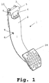
- FIG. 1 is a perspective view of an embodiment of the pedal invention with the parts of the pedal assembled.
- FIG. 2 is an exploded view of the pedal in FIG. 1.
- FIG. 3 is a perspective view of the support part of the pedal of the embodiment in FIG. 1 with the side walls removed.
- FIG. 4 is a perspective view of the support part of the pedal of the embodiment in FIG. 1 with the side walls in their assembled position.
- FIG. 5 is a cross-section of the pedal of the embodiment in FIG. 1.
- FIG. 6 is a profile view of the support part and the pedal body of the pedal of the embodiment in FIG. 1 during assembly of said pedal.
- FIG. 7 is a perspective view of the support part of a second embodiment of the invention.
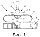
- FIG. 8 is a profile view and half section view of the support part in FIG. 7 before inserting the end of the rod into said support part.
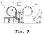
- FIG. 9 is a profile view and half section view of the support part in FIG. 7 once the end of the rod has been inserted into said support part.
- FIG. 10 is a perspective view of the lower end of the pedal body and the shoe, with an intermediate part between both parts.
-
- With reference to figures 1 and 2, the modular pedal comprises a
pedal body 2 which pivots around an axis of rotation 3, and asupport part 4 fixed to saidpedal body 2, it being possible for saidsupport part 4 to be made of a material different from that of which the pedal body is made 2, and said material preferably being plastic. Said supportpart 4, shown in detail in figures 3 and 4, comprises asocket 5 with ahole 6 for the axis of rotation 3, producing a joint between thepedal body 2 and said axis of rotation 3 via saidsupport part 4. - The
pedal body 2 comprises ahousing 7 into which thesupport part 4 is inserted, said supportpart 4 being joined to saidpedal body 2 via an elastic joint, preferably a detachable clip. As can be seen in figure 5, thepedal body 2 has a cross-section that is substantially U-shaped, thehousing 7 being delimited by said U-shape. Thesupport part 4 hasside projections 8, and saidpedal body 2 has holes or supports 9 into which saidprojections 8 fit. - The
pedal body 2 can comprise twoside extensions 10 that rest on part of the outer surface of thesocket 5 of thesupport part 4. In this embodiment, the outer surface of thesocket 5 is substantially cylindrical and theside projections 10 rest on approximately half of the outer perimeter of saidsocket 5. - The configuration of the
pedal body 2 and thesupport part 4 according to the invention allow quick and easy assembly of both parts. Figure 6 shows how said assembly is carried out. Firstly, thesocket 5 rests on thesupport part 4 on theside projections 10 of thepedal body 2, and thepedal body 2 is then inserted into thehousing 7 turning it indirection 31. - The
support part 4 can also comprise housing means 11 in which theend 12 of arod 13 is fitted via which a driving force is transmitted to an actuator, principally to a servo-brake or clutch cylinder. - In the embodiment in figures 1 to 6, the housing means 11 comprise an
elastic holding device 14 at the entrance of the housing means 11, andside walls 15, saidelastic holding device 14 being joined to saidside walls 15 and theside walls 15 being removable. Eachside wall 15 has a support orclip 16 which holds saidside wall 15 in its assembly position, and which transmits the force exerted by theend 12 of the actuator onto theholding device 14 to the whole of thesupport part 4. Theend 12 of therod 13 of the housing means 11 can be pulled out via the foldingside walls 15, if necessary. To do this, thesupport part 4 only has to be pulled out from thehousing 7 of thepedal body 2 and theside walls 15 removed. - In cases where a great amount of pressure is transmitted by the rod 13 a
jacket 30 may have to be inserted between theend 12 of therod 13 and the housing means 11 of thesupport part 4. In the embodiments shown in the drawings, theend 12 of therod 13 is spherical, with which saidjacket 30 has an almost semi-spherical surface. - In a second embodiment which comprises the
support part 4 shown in Figures 7, 8 and 9, the housing means 11 comprise amovable part 17 with ahousing 18 in which approximately half of theend 12 of therod 13 is fitted or, alternatively, thejacket 30, foldingside housings 19 hingedly joined to themovable part 17, laminatedside springs 20 joined to said foldinghousings 19, and asupport surface 21 for themovable part 17. - When during assembly the
end 12 of therod 13 presses on thehousing 18, the laminatedsprings 20 are compressed, themovable part 17 is moved to rest on thesurface 21, and thefolding housings 19 support theend 12 of therod 13 due to the action of the laminatedsprings 20, as shown in Figure 9. - In the embodiment in figures 7, 8 and 9, the
end 12 of therod 13 is substantially spherical, with which thehousing 18 has a substantially semi-spherical internal surface and thefolding housings 19 have an internal surface which is substantially a quarter of a sphere. Said foldinghousings 19 also have agroove 32 for holding therod 13. - In this embodiment, the
support part 4 also comprises foldingside walls 22, eachside wall 22 incorporating aflange 23, and thefolding housings 19 haveprojections 24, saidflanges 23 being shoed in theprojections 24 when theend 13 of therod 12 presses on thehousing 11 and themovable part 17 presses on thesurface 21. Theside walls 22 havelongitudinal guide bars 25 and themovable part 17 haslongitudinal grooves 26 , saidguide bars 25 being held in saidgrooves 26. Thesurface 21 of thesupport part 4 and thesurface 27 of themovable part 17 are cylindrical. - By means of this second embodiment a solution is obtained whereby, as in the first solution, the
end 12 of therod 13 can be easily released when necessary. In addition, the support part for theend 12, thehousing 18, is incorporated in thesupport part 4. Likewise, there is no need to include any funnelled surface to guide theend 12 of therod 13 towards thehousing 18, since the contact between both is made without any force. - With reference to figure 10, in the two embodiments described, the modular pedal comprises a
shoe 28 and anintermediate part 29 between saidshoe 28 and thepedal body 2, saidintermediate part 29 may be made of a different material from that of which thepedal body 2 is made, and said material preferably being plastic. Saidintermediate part 29 is joined elastically to thepedal body 2, preferably via a detachable clip. - By using the
intermediate part 29 thepedal body 2 adopts a straighter shape, so that it undergoes less force and can therefore contain less material or, otherwise, a material with less-demanding characteristics, which makespedal 1 lighter and/or cheaper. The use of saidintermediate part 29 allows the optimum position of theshoe 28 to be obtained with a simpler and sturdier geometry for thepedal body 2, now that saidpedal body 2 can be less curved. - The
shoe 28 and theintermediate part 29 can be embodied in a single integral part.
Claims (17)
- Modular pedal for vehicles which comprises a pedal body (2) which pivots around an axis of rotation (3), and a support part (4) fixed to said pedal body (2), it being possible for said support part (4) to be made of a material different from that of which the pedal body (2) is made, and said material preferably being plastic, characterised in that said support part (4) comprises a socket (5) with a hole (6) for the axis of rotation (3), producing a joint between the pedal body (2) and said axis of rotation (3) via said support part (4).
- Modular pedal according to claim 1, characterised in that the pedal body (2) comprises a housing (7) wherein the support part (4) is inserted, said support part (4) being joined to said pedal body (2) via an elastic joint, preferably a detachable clip.
- Modular pedal according to claim 2, characterised in that the pedal body (2) has a cross-section that is substantially U-shaped, the housing (7) being delimited by said U-shape, the support part (4) comprises side projections (8), and said pedal body (2) comprises holes or supports (9) wherein said projections fit (8).
- Modular pedal according to claim 3, characterised in that the pedal body (2) comprises two side extensions (10) which rest on part of the outer surface of the part (5) of the support part (4).
- Modular pedal according to claim 4, characterized in that the outer surface of the part (5) is substantially cylindrical and the side projections (10) rest on approximately half of the outer perimeter of said socket (5).
- Modular pedal according to claims 3, 4 or 5, characterised in that the support part (4) also comprises housing means (11) wherein the end (12) of a rod (13) is fitted via which a driving force is transmitted to an actuator, principally to a servo-brake or clutch cylinder.
- Modular pedal according to claim 6, characterised in that the housing means (11) comprise an elastic holding device (14) in the entrance of the housing means (11), and side walls (15), said holding device (14) being joined to said side walls (15) and said side walls (15) being foldable.
- Modular pedal according to claim 7, characterised in that each side wall (15) comprises at least one clip (16) which holds said side wall (15) in its assembly position, and which transmits the force exerted by the end (12) of the actuator onto the holding device (14) to the whole of the support part (4).
- Modular pedal according to claim 6, characterised in that the housing (11) comprises a movable part (17) with a housing (18) wherein approximately half of the end (12) of the rod (13) is fitted, folding side housings (19) hingedly joined to the movable part (17), laminated side springs (20) joined to said folding housings (20), and a support surface (21) for the movable part (17), in such a way that, when during assembly the end (12) of the rod (13) presses on the housing (18), the laminated springs (20) are compressed, the movable part (17) is moved to rest on the surface (21), and the folding housings (19) support the end (12) of the rod (13) due to the action of the laminated springs (20).
- Modular pedal according to claim 9, characterised in that the end (12) of the rod (13) is substantially spherical, the housing (18) has a substantially semi-spherical internal surface, and the folding housings (19) have an internal surface which are substantially a quarter of a sphere, said folding housings (19) also having a groove (21) for holding the rod (13).
- Modular pedal according to claim 9 or 10, characterised in that the support part (4) also comprises folding side walls (22), each side wall (22) incorporating a flange (23), and the folding housings (19) comprise projections (24), said flanges (23) being shoed in the projections (24) when the end (13) of the rod (12) presses on the housing (11) and the movable part (10) presses on the surface (21).
- Modular pedal according to claim 11, characterised in that the side walls (22) comprise longitudinal guide bars (25) and the longitudinal movable part (10) has grooves (26), said guide bars (25) being held in said grooves (26).
- Modular pedal according to any of claims 9 to 12, characterised in that the surface (21) and the surface (27) of the movable part (10) are cylindrical.
- Modular pedal according to any of the preceding claims, characterised in that it comprises a shoe (28) and an intermediate part (29) between said shoe (28) and the pedal body (2), said intermediate part (29) may be made of a different material from that of which the pedal body (2) is made, and said material preferably being plastic.
- Modular pedal according to claim 14, characterised in that said intermediate part (29) is joined elastically to the pedal body (2), preferably via a detachable clip.
- Modular pedal according to claim 14, characterised in that the shoe (28) and the intermediate part (29) make up a single integral part.
- Modular pedal according to any of the preceding claims, characterised in that the housing (18) has a jacket (30) on which the end (12) of the rod (13) rests.
Applications Claiming Priority (2)
| Application Number | Priority Date | Filing Date | Title |
|---|---|---|---|
| ES200201577A ES2208086B1 (en) | 2002-07-05 | 2002-07-05 | MODULAR PEDAL. |
| ES200201577 | 2002-07-05 |
Publications (2)
| Publication Number | Publication Date |
|---|---|
| EP1378409A1 true EP1378409A1 (en) | 2004-01-07 |
| EP1378409B1 EP1378409B1 (en) | 2005-09-28 |
Family
ID=29719837
Family Applications (1)
| Application Number | Title | Priority Date | Filing Date |
|---|---|---|---|
| EP03380147A Expired - Lifetime EP1378409B1 (en) | 2002-07-05 | 2003-06-20 | Modular pedal |
Country Status (4)
| Country | Link |
|---|---|
| EP (1) | EP1378409B1 (en) |
| AT (1) | ATE305400T1 (en) |
| DE (1) | DE60301700T2 (en) |
| ES (2) | ES2208086B1 (en) |
Cited By (4)
| Publication number | Priority date | Publication date | Assignee | Title |
|---|---|---|---|---|
| FR2869424A1 (en) * | 2004-04-21 | 2005-10-28 | Bosch Gmbh Robert | Control unit e.g. brake pedal, for motor vehicle, has pins whose bases open in opening via which control rod head passes, where pins` intermediate parts are maintained in direction by retention unit that limits bases in another direction |
| DE102006032153A1 (en) * | 2006-07-12 | 2008-01-24 | Daimler Ag | Method for fitting pedal onto support arm especially for vehicle control pedals has the shaped end of the arm snap fitted into a recess in the rear of the pedal |
| US7441478B2 (en) * | 2003-06-24 | 2008-10-28 | Zf Boge Elastmetall Gmbh | Pedal with fastening clip for push rod |
| CN103838293A (en) * | 2012-11-20 | 2014-06-04 | 苏州工业园区高登威科技有限公司 | Pedal fixing device |
Families Citing this family (3)
| Publication number | Priority date | Publication date | Assignee | Title |
|---|---|---|---|---|
| DE102009042402A1 (en) | 2009-09-21 | 2011-03-24 | Volkswagen Ag | Pedal arrangement for vehicle, particularly motor vehicle, has bearing block and pedal lever which is pivotally supported between side cheeks of bearing block by bearing axis |
| DE102010049866A1 (en) * | 2010-10-28 | 2012-05-03 | Volkswagen Ag | Actuator with a pedal and an articulated to this push rod |
| DE102018222273B4 (en) * | 2018-12-19 | 2020-09-17 | Volkswagen Aktiengesellschaft | Arrangement for attaching a push rod to a pedal lever, vehicle braking system for this and vehicle with such |
Citations (3)
| Publication number | Priority date | Publication date | Assignee | Title |
|---|---|---|---|---|
| US5690000A (en) * | 1996-03-13 | 1997-11-25 | General Motors Corporation | Brake pedal with self-aligning bracket |
| EP0896162A1 (en) * | 1997-08-07 | 1999-02-10 | S.I.V. S.p.A. | Locking device for the brake pedal of a vehicle to the pressure rod of a power brake |
| EP1260419A1 (en) * | 2001-05-23 | 2002-11-27 | FIAT AUTO S.p.A. | A system for releasing a pedal of a motor vehicle in the event of a frontal impact |
-
2002
- 2002-07-05 ES ES200201577A patent/ES2208086B1/en not_active Expired - Fee Related
-
2003
- 2003-06-20 DE DE60301700T patent/DE60301700T2/en not_active Expired - Lifetime
- 2003-06-20 AT AT03380147T patent/ATE305400T1/en not_active IP Right Cessation
- 2003-06-20 EP EP03380147A patent/EP1378409B1/en not_active Expired - Lifetime
- 2003-06-20 ES ES03380147T patent/ES2250861T3/en not_active Expired - Lifetime
Patent Citations (3)
| Publication number | Priority date | Publication date | Assignee | Title |
|---|---|---|---|---|
| US5690000A (en) * | 1996-03-13 | 1997-11-25 | General Motors Corporation | Brake pedal with self-aligning bracket |
| EP0896162A1 (en) * | 1997-08-07 | 1999-02-10 | S.I.V. S.p.A. | Locking device for the brake pedal of a vehicle to the pressure rod of a power brake |
| EP1260419A1 (en) * | 2001-05-23 | 2002-11-27 | FIAT AUTO S.p.A. | A system for releasing a pedal of a motor vehicle in the event of a frontal impact |
Cited By (4)
| Publication number | Priority date | Publication date | Assignee | Title |
|---|---|---|---|---|
| US7441478B2 (en) * | 2003-06-24 | 2008-10-28 | Zf Boge Elastmetall Gmbh | Pedal with fastening clip for push rod |
| FR2869424A1 (en) * | 2004-04-21 | 2005-10-28 | Bosch Gmbh Robert | Control unit e.g. brake pedal, for motor vehicle, has pins whose bases open in opening via which control rod head passes, where pins` intermediate parts are maintained in direction by retention unit that limits bases in another direction |
| DE102006032153A1 (en) * | 2006-07-12 | 2008-01-24 | Daimler Ag | Method for fitting pedal onto support arm especially for vehicle control pedals has the shaped end of the arm snap fitted into a recess in the rear of the pedal |
| CN103838293A (en) * | 2012-11-20 | 2014-06-04 | 苏州工业园区高登威科技有限公司 | Pedal fixing device |
Also Published As
| Publication number | Publication date |
|---|---|
| ES2208086A1 (en) | 2004-06-01 |
| ES2250861T3 (en) | 2006-04-16 |
| ES2208086B1 (en) | 2005-08-16 |
| DE60301700T2 (en) | 2006-07-06 |
| ATE305400T1 (en) | 2005-10-15 |
| DE60301700D1 (en) | 2006-02-09 |
| EP1378409B1 (en) | 2005-09-28 |
Similar Documents
| Publication | Publication Date | Title |
|---|---|---|
| US8197155B2 (en) | Connecting device of parking cable for electric parking brake | |
| EP1078843B1 (en) | Telescopic shaft for steering columns in automobiles with a sliding load control system | |
| US9389633B2 (en) | Motor vehicle pedal coupling apparatus and method | |
| WO2006133693A3 (en) | Ball joint | |
| EP1378409A1 (en) | Modular pedal | |
| US6205883B1 (en) | Adjustable pedal-pocketed gears | |
| US20120240716A1 (en) | Electronic clutch pedal assembly having varying resistance | |
| US5934151A (en) | Vehicle push rod and pedal assembly | |
| JPH05215204A (en) | Noise vibration damping assembly for shift-lever mechanism and forming method thereof | |
| KR20140074325A (en) | Connecting assembly for a vehicle | |
| CN108027626B (en) | Pedal device with actuation damping | |
| KR101292624B1 (en) | Apparatus for sensor mounting of clutch master clinder | |
| JP3660022B2 (en) | Change device for transmission | |
| JP2007506595A (en) | Pedal with fixed clip for pressing rod | |
| US11118640B2 (en) | Wet parking brake device and method of assembling the same | |
| KR102490767B1 (en) | Actuator including drive unit and electric unit | |
| DE60122805D1 (en) | Manufacturing method for a brake pedal assembly for a motor vehicle | |
| EP0721073A2 (en) | Change lever supporting structure | |
| EP1920163A1 (en) | Adjustment device for a control cable | |
| US10875565B2 (en) | Steering arrangement | |
| US20190219096A1 (en) | Ball joint device | |
| KR100803808B1 (en) | A clutch mastering cylinder assembly for vehicle | |
| WO2023189396A1 (en) | Electric brake device | |
| JP2010031943A (en) | Control cable connecting device | |
| CN110225837A (en) | Universal-joint fork and actuator with universal-joint fork |
Legal Events
| Date | Code | Title | Description |
|---|---|---|---|
| EUG | Se: european patent has lapsed | ||
| PUAI | Public reference made under article 153(3) epc to a published international application that has entered the european phase |
Free format text: ORIGINAL CODE: 0009012 |
|
| AK | Designated contracting states |
Kind code of ref document: A1 Designated state(s): AT BE BG CH CY CZ DE DK EE ES FI FR GB GR HU IE IT LI LU MC NL PT RO SE SI SK TR |
|
| AX | Request for extension of the european patent |
Extension state: AL LT LV MK |
|
| 17P | Request for examination filed |
Effective date: 20040607 |
|
| 17Q | First examination report despatched |
Effective date: 20040706 |
|
| AKX | Designation fees paid |
Designated state(s): AT BE BG CH CY CZ DE DK EE ES FI FR GB GR HU IE IT LI LU MC NL PT RO SE SI SK TR |
|
| GRAP | Despatch of communication of intention to grant a patent |
Free format text: ORIGINAL CODE: EPIDOSNIGR1 |
|
| GRAS | Grant fee paid |
Free format text: ORIGINAL CODE: EPIDOSNIGR3 |
|
| GRAA | (expected) grant |
Free format text: ORIGINAL CODE: 0009210 |
|
| AK | Designated contracting states |
Kind code of ref document: B1 Designated state(s): AT BE BG CH CY CZ DE DK EE ES FI FR GB GR HU IE IT LI LU MC NL PT RO SE SI SK TR |
|
| PG25 | Lapsed in a contracting state [announced via postgrant information from national office to epo] |
Ref country code: CH Free format text: LAPSE BECAUSE OF FAILURE TO SUBMIT A TRANSLATION OF THE DESCRIPTION OR TO PAY THE FEE WITHIN THE PRESCRIBED TIME-LIMIT Effective date: 20050928 Ref country code: SK Free format text: LAPSE BECAUSE OF FAILURE TO SUBMIT A TRANSLATION OF THE DESCRIPTION OR TO PAY THE FEE WITHIN THE PRESCRIBED TIME-LIMIT Effective date: 20050928 Ref country code: FI Free format text: LAPSE BECAUSE OF FAILURE TO SUBMIT A TRANSLATION OF THE DESCRIPTION OR TO PAY THE FEE WITHIN THE PRESCRIBED TIME-LIMIT Effective date: 20050928 Ref country code: BE Free format text: LAPSE BECAUSE OF FAILURE TO SUBMIT A TRANSLATION OF THE DESCRIPTION OR TO PAY THE FEE WITHIN THE PRESCRIBED TIME-LIMIT Effective date: 20050928 Ref country code: LI Free format text: LAPSE BECAUSE OF FAILURE TO SUBMIT A TRANSLATION OF THE DESCRIPTION OR TO PAY THE FEE WITHIN THE PRESCRIBED TIME-LIMIT Effective date: 20050928 Ref country code: RO Free format text: LAPSE BECAUSE OF FAILURE TO SUBMIT A TRANSLATION OF THE DESCRIPTION OR TO PAY THE FEE WITHIN THE PRESCRIBED TIME-LIMIT Effective date: 20050928 Ref country code: AT Free format text: LAPSE BECAUSE OF FAILURE TO SUBMIT A TRANSLATION OF THE DESCRIPTION OR TO PAY THE FEE WITHIN THE PRESCRIBED TIME-LIMIT Effective date: 20050928 Ref country code: NL Free format text: LAPSE BECAUSE OF FAILURE TO SUBMIT A TRANSLATION OF THE DESCRIPTION OR TO PAY THE FEE WITHIN THE PRESCRIBED TIME-LIMIT Effective date: 20050928 Ref country code: SI Free format text: LAPSE BECAUSE OF FAILURE TO SUBMIT A TRANSLATION OF THE DESCRIPTION OR TO PAY THE FEE WITHIN THE PRESCRIBED TIME-LIMIT Effective date: 20050928 Ref country code: CZ Free format text: LAPSE BECAUSE OF FAILURE TO SUBMIT A TRANSLATION OF THE DESCRIPTION OR TO PAY THE FEE WITHIN THE PRESCRIBED TIME-LIMIT Effective date: 20050928 |
|
| REG | Reference to a national code |
Ref country code: GB Ref legal event code: FG4D |
|
| REG | Reference to a national code |
Ref country code: CH Ref legal event code: EP |
|
| REG | Reference to a national code |
Ref country code: IE Ref legal event code: FG4D |
|
| PG25 | Lapsed in a contracting state [announced via postgrant information from national office to epo] |
Ref country code: DK Free format text: LAPSE BECAUSE OF FAILURE TO SUBMIT A TRANSLATION OF THE DESCRIPTION OR TO PAY THE FEE WITHIN THE PRESCRIBED TIME-LIMIT Effective date: 20051228 Ref country code: BG Free format text: LAPSE BECAUSE OF FAILURE TO SUBMIT A TRANSLATION OF THE DESCRIPTION OR TO PAY THE FEE WITHIN THE PRESCRIBED TIME-LIMIT Effective date: 20051228 Ref country code: GR Free format text: LAPSE BECAUSE OF FAILURE TO SUBMIT A TRANSLATION OF THE DESCRIPTION OR TO PAY THE FEE WITHIN THE PRESCRIBED TIME-LIMIT Effective date: 20051228 |
|
| REG | Reference to a national code |
Ref country code: SE Ref legal event code: TRGR |
|
| REF | Corresponds to: |
Ref document number: 60301700 Country of ref document: DE Date of ref document: 20060209 Kind code of ref document: P |
|
| PG25 | Lapsed in a contracting state [announced via postgrant information from national office to epo] |
Ref country code: PT Free format text: LAPSE BECAUSE OF FAILURE TO SUBMIT A TRANSLATION OF THE DESCRIPTION OR TO PAY THE FEE WITHIN THE PRESCRIBED TIME-LIMIT Effective date: 20060228 |
|
| NLV1 | Nl: lapsed or annulled due to failure to fulfill the requirements of art. 29p and 29m of the patents act | ||
| PG25 | Lapsed in a contracting state [announced via postgrant information from national office to epo] |
Ref country code: HU Free format text: LAPSE BECAUSE OF FAILURE TO SUBMIT A TRANSLATION OF THE DESCRIPTION OR TO PAY THE FEE WITHIN THE PRESCRIBED TIME-LIMIT Effective date: 20060329 |
|
| REG | Reference to a national code |
Ref country code: CH Ref legal event code: PL |
|
| REG | Reference to a national code |
Ref country code: ES Ref legal event code: FG2A Ref document number: 2250861 Country of ref document: ES Kind code of ref document: T3 |
|
| PGFP | Annual fee paid to national office [announced via postgrant information from national office to epo] |
Ref country code: SE Payment date: 20060616 Year of fee payment: 4 |
|
| PG25 | Lapsed in a contracting state [announced via postgrant information from national office to epo] |
Ref country code: IE Free format text: LAPSE BECAUSE OF NON-PAYMENT OF DUE FEES Effective date: 20060620 |
|
| ET | Fr: translation filed | ||
| PG25 | Lapsed in a contracting state [announced via postgrant information from national office to epo] |
Ref country code: MC Free format text: LAPSE BECAUSE OF NON-PAYMENT OF DUE FEES Effective date: 20060630 |
|
| PGFP | Annual fee paid to national office [announced via postgrant information from national office to epo] |
Ref country code: IT Payment date: 20060630 Year of fee payment: 4 |
|
| PLBE | No opposition filed within time limit |
Free format text: ORIGINAL CODE: 0009261 |
|
| STAA | Information on the status of an ep patent application or granted ep patent |
Free format text: STATUS: NO OPPOSITION FILED WITHIN TIME LIMIT |
|
| 26N | No opposition filed |
Effective date: 20060629 |
|
| REG | Reference to a national code |
Ref country code: IE Ref legal event code: MM4A |
|
| EUG | Se: european patent has lapsed | ||
| GBPC | Gb: european patent ceased through non-payment of renewal fee |
Effective date: 20070620 |
|
| PG25 | Lapsed in a contracting state [announced via postgrant information from national office to epo] |
Ref country code: GB Free format text: LAPSE BECAUSE OF NON-PAYMENT OF DUE FEES Effective date: 20070620 |
|
| PG25 | Lapsed in a contracting state [announced via postgrant information from national office to epo] |
Ref country code: SE Free format text: LAPSE BECAUSE OF NON-PAYMENT OF DUE FEES Effective date: 20070621 Ref country code: EE Free format text: LAPSE BECAUSE OF FAILURE TO SUBMIT A TRANSLATION OF THE DESCRIPTION OR TO PAY THE FEE WITHIN THE PRESCRIBED TIME-LIMIT Effective date: 20050928 |
|
| PG25 | Lapsed in a contracting state [announced via postgrant information from national office to epo] |
Ref country code: LU Free format text: LAPSE BECAUSE OF NON-PAYMENT OF DUE FEES Effective date: 20060620 Ref country code: TR Free format text: LAPSE BECAUSE OF FAILURE TO SUBMIT A TRANSLATION OF THE DESCRIPTION OR TO PAY THE FEE WITHIN THE PRESCRIBED TIME-LIMIT Effective date: 20050928 |
|
| PG25 | Lapsed in a contracting state [announced via postgrant information from national office to epo] |
Ref country code: CY Free format text: LAPSE BECAUSE OF FAILURE TO SUBMIT A TRANSLATION OF THE DESCRIPTION OR TO PAY THE FEE WITHIN THE PRESCRIBED TIME-LIMIT Effective date: 20050928 |
|
| PG25 | Lapsed in a contracting state [announced via postgrant information from national office to epo] |
Ref country code: IT Free format text: LAPSE BECAUSE OF NON-PAYMENT OF DUE FEES Effective date: 20070620 |
|
| PGFP | Annual fee paid to national office [announced via postgrant information from national office to epo] |
Ref country code: ES Payment date: 20120606 Year of fee payment: 10 |
|
| PGFP | Annual fee paid to national office [announced via postgrant information from national office to epo] |
Ref country code: FR Payment date: 20130703 Year of fee payment: 11 |
|
| REG | Reference to a national code |
Ref country code: FR Ref legal event code: ST Effective date: 20150227 |
|
| PG25 | Lapsed in a contracting state [announced via postgrant information from national office to epo] |
Ref country code: FR Free format text: LAPSE BECAUSE OF NON-PAYMENT OF DUE FEES Effective date: 20140630 |
|
| REG | Reference to a national code |
Ref country code: ES Ref legal event code: FD2A Effective date: 20150724 |
|
| PG25 | Lapsed in a contracting state [announced via postgrant information from national office to epo] |
Ref country code: ES Free format text: LAPSE BECAUSE OF NON-PAYMENT OF DUE FEES Effective date: 20140621 |
|
| PGFP | Annual fee paid to national office [announced via postgrant information from national office to epo] |
Ref country code: DE Payment date: 20210629 Year of fee payment: 19 |
|
| REG | Reference to a national code |
Ref country code: DE Ref legal event code: R119 Ref document number: 60301700 Country of ref document: DE |
|
| PG25 | Lapsed in a contracting state [announced via postgrant information from national office to epo] |
Ref country code: DE Free format text: LAPSE BECAUSE OF NON-PAYMENT OF DUE FEES Effective date: 20230103 |