EP1378392B1 - Container with movable bulkheads - Google Patents
Container with movable bulkheads Download PDFInfo
- Publication number
- EP1378392B1 EP1378392B1 EP03254217A EP03254217A EP1378392B1 EP 1378392 B1 EP1378392 B1 EP 1378392B1 EP 03254217 A EP03254217 A EP 03254217A EP 03254217 A EP03254217 A EP 03254217A EP 1378392 B1 EP1378392 B1 EP 1378392B1
- Authority
- EP
- European Patent Office
- Prior art keywords
- container
- heat exchanger
- housing
- movable
- compartments
- Prior art date
- Legal status (The legal status is an assumption and is not a legal conclusion. Google has not performed a legal analysis and makes no representation as to the accuracy of the status listed.)
- Expired - Lifetime
Links
Images


Classifications
-
- F—MECHANICAL ENGINEERING; LIGHTING; HEATING; WEAPONS; BLASTING
- F25—REFRIGERATION OR COOLING; COMBINED HEATING AND REFRIGERATION SYSTEMS; HEAT PUMP SYSTEMS; MANUFACTURE OR STORAGE OF ICE; LIQUEFACTION SOLIDIFICATION OF GASES
- F25D—REFRIGERATORS; COLD ROOMS; ICE-BOXES; COOLING OR FREEZING APPARATUS NOT OTHERWISE PROVIDED FOR
- F25D23/00—General constructional features
- F25D23/06—Walls
- F25D23/069—Cooling space dividing partitions
-
- B—PERFORMING OPERATIONS; TRANSPORTING
- B60—VEHICLES IN GENERAL
- B60H—ARRANGEMENTS OF HEATING, COOLING, VENTILATING OR OTHER AIR-TREATING DEVICES SPECIALLY ADAPTED FOR PASSENGER OR GOODS SPACES OF VEHICLES
- B60H1/00—Heating, cooling or ventilating devices
- B60H1/00007—Combined heating, ventilating, or cooling devices
- B60H1/00014—Combined heating, ventilating, or cooling devices for load cargos on load transporting vehicles
-
- B—PERFORMING OPERATIONS; TRANSPORTING
- B60—VEHICLES IN GENERAL
- B60P—VEHICLES ADAPTED FOR LOAD TRANSPORTATION OR TO TRANSPORT, TO CARRY, OR TO COMPRISE SPECIAL LOADS OR OBJECTS
- B60P3/00—Vehicles adapted to transport, to carry or to comprise special loads or objects
- B60P3/20—Refrigerated goods vehicles
- B60P3/205—Refrigerated goods vehicles with means for dividing the interior volume, e.g. movable walls or intermediate floors
-
- F—MECHANICAL ENGINEERING; LIGHTING; HEATING; WEAPONS; BLASTING
- F25—REFRIGERATION OR COOLING; COMBINED HEATING AND REFRIGERATION SYSTEMS; HEAT PUMP SYSTEMS; MANUFACTURE OR STORAGE OF ICE; LIQUEFACTION SOLIDIFICATION OF GASES
- F25D—REFRIGERATORS; COLD ROOMS; ICE-BOXES; COOLING OR FREEZING APPARATUS NOT OTHERWISE PROVIDED FOR
- F25D11/00—Self-contained movable devices, e.g. domestic refrigerators
- F25D11/003—Transport containers
Definitions
- This invention relates to a container for storing goods in a plurality of temperature controlled compartments and, in particular, to a container having a plurality of multi-temperature compartments wherein the volume of the compartments can be selectively changed to better accommodate varying loads.
- this invention relates to a mobile container for transporting goods that require the atmosphere in the container to be temperature controlled.
- the container is equipped with a single air conditioning unit that is adapted to maintain the interior of the container at a given temperature.
- the container is generally required to carry a full load of one class of goods.
- GB-A-2211922 discloses a refrigerated container having the features of the preamble of claim 1.
- a further object of the present invention is to provide a mobile container having a plurality of compartments each of which can be independently temperature controlled.
- a still further object of the present invention is to provide a mobile container having a plurality of temperature controlled compartments the volume of which can be selectively varied to facilitate different classes of temperature sensitive goods.
- the container is generally rectangular in form and contains two opposed side walls 12 and 13, two end walls 14 and 15 as well as a roof or ceiling 16 and a floor 17.
- the container is mobile being equipped with a plurality of wheels 20-20 that enables the container to be transported from place to place by a tractor or the like (not shown).
- Two sets of parallel rails 22 and 23 are suspended inside the container from the container roof.
- two bulkheads 25 and 26 are hung from the rails so that they can be repositioned substantially along the entire length of the container.
- the bulkheads extend across the width of the container to divide the container into three separate compartments that include two end compartments, and 27 and 28 and a center compartment 30.
- the bulkheads are provided with appropriate peripheral seals so that the air in each compartment can be individually conditioned to a desired temperature level.
- the bulkheads can be moved over the rails to an infinite number of locations thereby altering the volume of the compartments to satisfy changing load demands.
- the two end compartments are each serviced by an air conditioning unit such as unit 32 mounted upon an adjacent end wall of the compartment
- a separate heat exchanger, such as heat exchanger 33 is also mounted in each end compartment, preferably from the ceiling through which conditioned air is exchanged for compartment return air.
- the center compartment is serviced by another air conditioning unit 34 that may be located beneath the floor of the container or any other convenient place.
- a heat exchanger 35 is mounted within the center compartment. As will be explained in greater detail below, the heat exchanger is coupled to air conditioning unit 34 by flexible service lines.
- the heat exchanger 35 is movably suspended from rails 23 and can be repositioned substantially along the entire length of the container along with the bulkheads.
- each bulkhead can be fabricated as a one piece section
- the present bulkheads include two separate panels 38 and 39 that are suspended from rail sets 22 and 23, respectively, so that each panel can be independently repositioned with relative ease by one person.
- the heat exchanger 35 is mounted upon rails 23 adjacent to one of the panels 39. The heat exchanger and the panel joined together so that the two can be moved as a unit along rails 23.
- the heat exchanger 35 contains a series of rollers 40 that are slidably contained in the rails 22 so that heat exchanger can roll easily to any one of an infinite number of positions along the length of the rails.
- the panels 38 and 39 are similarly suspended from the rails.
- the heat exchanger 35 is attached to an adjacent one of the panels by means of a pair of tie rods 42 so that the heat exchanger and the panel remain connected as the panel is being rolled along the rails to a selected position.
- seals are mounted about the entire periphery of each panel and are arranged to ride in sealing contact against the side walls, ceiling and floor of the container to prevent air from moving therebetween.
- a separate vertically disposed seal 46 is also mounted along the inboard edge of each panel.
- the inboard seals of the two panels making up one of the bulkheads are adapted to mate when the panels are brought into coplanar alignment thereby preventing air from moving between the panels.
- the panel may be positioned so that three separate compartments are established within the container and the size of each compartment can be varied within the range of the rails to accommodate a given load.
- the temperature level within each compartment may also be individually regulated to a desired setting best suited to preserve the goods store therein.
- the housing 50 consists of a channel shaped trough having a bottom wall 55 and a pair of side walls 56 and 57. A pair of side flanges 60 and 61 are attached to the side walls which contain blocks of insulation 63. In assembly the body of the channel shaped housing closes against the ceiling of the container and the housing is totally enclosed by a pair of end walls (not shown). As illustrated in Figs. 3 and 4 , a fixed connector 65 is mounted in the bottom wall of the housing and serves to couple refrigeration lines and electrical lines extend along the bottom wall of the housing to one end of flexible conduits 48 and 49 located inside the housing. As illustrated in Fig.
- flexible conduit 48 includes a tubular sheath 70 that contains a refrigerant supply line 71 and a refrigerant return line 72.
- the flexible electric conduit 49 includes a tubular sheath 74 that contains an electrical cable 75. The other end of each flexible service conduit, in turn, are coupled to a movable connector 70.
- the flexible tubes that carry the service lines are contained within the housing between an outer chain 85 and a spaced apart inner chain 86.
- the chains are formed of plastic links 87 that have a vertical height that is slightly less than the height of the housing body. When the housing body is closed against the ceiling of the container, the links of the chains are held in an upright posture as illustrated in Fig. 6 . Each link is pivotably secured to its neighbor by a vertically disposed pin 88.
- the chains are arranged in the housing so that establish a well defined U-configuration between the side walls of the housing. The length of the chains are such that they will hold the U-shaped configuration as the heat exchanger moves back and forth over its prescribed path of travel. Accordingly, the flexible conduits captured between the chains are able to track along with the heat exchanger without twisting or snagging while at the same time preserving the air tight integrity of the compartments
- the heat exchanger 35 particularly when operating as an evaporator, will develop condensate.
- the condensate is collected in the pan 89 ( Fig. 5 ) of the unit which is contoured to direct the condensate to a drain that includes a drain pipe 90.
- the drain pipe is arranged to pass through an elongated vertically disposed slot 91 in one side wall of a trough 92.
- the trough is mounted in one side wall 13 of the container adjacent to the path of travel of the heat exchanger 35 and extends along the path of travel of the heat exchanger.
- the elongated opening in the trough is closed by a penetratable seal 93 through which the drain pipe passes.
- the trough is arranged to direct the condensate to an outlet which discharges the condensate from the container.
Landscapes
- Engineering & Computer Science (AREA)
- Physics & Mathematics (AREA)
- Mechanical Engineering (AREA)
- Thermal Sciences (AREA)
- Chemical & Material Sciences (AREA)
- Combustion & Propulsion (AREA)
- General Engineering & Computer Science (AREA)
- Health & Medical Sciences (AREA)
- Public Health (AREA)
- Transportation (AREA)
- Packages (AREA)
Description
- This invention relates to a container for storing goods in a plurality of temperature controlled compartments and, in particular, to a container having a plurality of multi-temperature compartments wherein the volume of the compartments can be selectively changed to better accommodate varying loads.
- More specifically, this invention relates to a mobile container for transporting goods that require the atmosphere in the container to be temperature controlled. Generally, the container is equipped with a single air conditioning unit that is adapted to maintain the interior of the container at a given temperature. To be profitable, the container is generally required to carry a full load of one class of goods. Some containers have been devised having a plurality of internal compartments, however, maintaining the compartments at different temperature has proven to be rather difficult. In addition, the volume and thus the carrying capacity of each compartment is fixed providing little in the way of flexibility to accommodate various size loads.
-
GB-A-2211922 - It is therefore an object of the present invention to improve containers for storing goods and, in particular, mobile containers for transporting goods that require a temperature controlled environment.
- A further object of the present invention is to provide a mobile container having a plurality of compartments each of which can be independently temperature controlled.
- A still further object of the present invention is to provide a mobile container having a plurality of temperature controlled compartments the volume of which can be selectively varied to facilitate different classes of temperature sensitive goods.
- These and other objects of the present invention are attained by an enclosed container for storing temperature sensitive goods that has opposed side walls and end walls, a floor and a ceiling. First and second intermediate bulkheads are movably supported within the container which serve to divide the container into three compartments. By repositioning the bulkheads, the volume and thus the load carrying capacity of the compartments can be varied. The two end compartments of the container are serviced by fixed heat exchangers while the center compartment is serviced by a movable heat exchanger whereby the temperature in each compartment can be tightly controlled at differing levels.
- For a better understanding of the invention, reference will be made to the following detailed description of the invention which is to be read in association with the accompanying drawing, wherein:
-
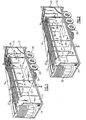
FIG. 1 is a perspective view of a mobile container that embodies the teachings of the present invention; -
FIG. 2 is a perspective view of the mobile container illustrated inFig. 1 further showing movable wall panels utilized in the practice of the invention being relocated; -
FIG. 3 is an enlarged partial top view in perspective with sections broken away illustrating the moving heat exchanger employed in the practice of the present invention and the housing that contains the lines for servicing the heat exchanger; -
FIG. 4 is a view similar to that inFig. 3 further illustrating the chain mechanism for guiding the service lines within the housing as the heat exchanger is being repositioned; -
FIG. 5 is an enlarged partial end view in section illustrating the heat exchanger being suspended from rails located in the ceiling of the container; -
FIG. 6 is a sectional view taken along lines 6-6 inFig. 3 ; -
FIG. 7 is a partial perspective view of a drain trough for carrying away condensation developed in the movable condenser; and -
FIG. 8 is an enlarged partial perspective view further illustrating a service line connector for coupling the service lines to the heat exchanger. - Turning now to
Figs. 1 and 2 , there is illustrated an enclosed container generally referenced 10, that embodies the teaching of the present invention. The container is generally rectangular in form and contains twoopposed side walls end walls ceiling 16 and afloor 17. Preferably, the container is mobile being equipped with a plurality of wheels 20-20 that enables the container to be transported from place to place by a tractor or the like (not shown). Two sets ofparallel rails bulkheads center compartment 30. - The bulkheads are provided with appropriate peripheral seals so that the air in each compartment can be individually conditioned to a desired temperature level. The bulkheads can be moved over the rails to an infinite number of locations thereby altering the volume of the compartments to satisfy changing load demands.
- The two end compartments are each serviced by an air conditioning unit such as
unit 32 mounted upon an adjacent end wall of the compartment A separate heat exchanger, such asheat exchanger 33 is also mounted in each end compartment, preferably from the ceiling through which conditioned air is exchanged for compartment return air. The center compartment is serviced by anotherair conditioning unit 34 that may be located beneath the floor of the container or any other convenient place. Aheat exchanger 35 is mounted within the center compartment. As will be explained in greater detail below, the heat exchanger is coupled toair conditioning unit 34 by flexible service lines. Theheat exchanger 35 is movably suspended fromrails 23 and can be repositioned substantially along the entire length of the container along with the bulkheads. - Although each bulkhead can be fabricated as a one piece section, the present bulkheads include two
separate panels rail sets Fig. 2 , theheat exchanger 35 is mounted uponrails 23 adjacent to one of thepanels 39. The heat exchanger and the panel joined together so that the two can be moved as a unit alongrails 23. - Turning now to
Figs. 3 and5 , theheat exchanger 35 contains a series ofrollers 40 that are slidably contained in therails 22 so that heat exchanger can roll easily to any one of an infinite number of positions along the length of the rails. Thepanels heat exchanger 35 is attached to an adjacent one of the panels by means of a pair oftie rods 42 so that the heat exchanger and the panel remain connected as the panel is being rolled along the rails to a selected position. - As best illustrated in
Fig. 5 , seals are mounted about the entire periphery of each panel and are arranged to ride in sealing contact against the side walls, ceiling and floor of the container to prevent air from moving therebetween. A separate vertically disposedseal 46 is also mounted along the inboard edge of each panel. The inboard seals of the two panels making up one of the bulkheads are adapted to mate when the panels are brought into coplanar alignment thereby preventing air from moving between the panels. As should be now evident, the panel may be positioned so that three separate compartments are established within the container and the size of each compartment can be varied within the range of the rails to accommodate a given load. In addition, because each compartment is serviced by an individual air conditioning unit, the temperature level within each compartment may also be individually regulated to a desired setting best suited to preserve the goods store therein. - As shown in
Fig. 6 , the service to the heat exchanger is carried byflexible conduits rails 22. The height of the housing is slightly less than that of thepanel seal 45 and accordingly, the housing fits between the top edge of thepanel 39 and theroof 16 of the container. A thinauxiliary seal 53 is secured to the outside surface of the housing floor which rides in sealing contact against the panel to prevent air from passing therebetween. - The
housing 50 consists of a channel shaped trough having abottom wall 55 and a pair ofside walls side flanges 60 and 61 are attached to the side walls which contain blocks ofinsulation 63. In assembly the body of the channel shaped housing closes against the ceiling of the container and the housing is totally enclosed by a pair of end walls (not shown). As illustrated inFigs. 3 and4 , afixed connector 65 is mounted in the bottom wall of the housing and serves to couple refrigeration lines and electrical lines extend along the bottom wall of the housing to one end offlexible conduits Fig. 6 ,flexible conduit 48 includes atubular sheath 70 that contains arefrigerant supply line 71 and arefrigerant return line 72. The flexibleelectric conduit 49 includes atubular sheath 74 that contains anelectrical cable 75. The other end of each flexible service conduit, in turn, are coupled to amovable connector 70. - The opposite ends of the flexible conduits are attached to a movable connector generally referenced 77. The movable connector includes a bracket for supporting the refrigerant and electrical conduits. The bracket slidably is mounted upon the bottom wall of the housing. The two conduits are further supported in a
slide plate 82 of the bracket so that they can pass downwardly toward theheat exchanger 35 through an elongated slottedopening 83 provided in the bottom wall of the housing. Apenetratable seal 84 is carried in theopening 83 that permits the conduits to pass out of the housing without appreciable loss of air from the compartments. A rigid L-shapedarm 94 is attached at one end to the bracket and passes downwardly through the seal. The opposite end of the arm is secured to theheat exchanger 35 so that the bracket and the heat exchanger move together when the heat exchanger is being repositioned. - The flexible tubes that carry the service lines are contained within the housing between an
outer chain 85 and a spaced apartinner chain 86. The chains are formed ofplastic links 87 that have a vertical height that is slightly less than the height of the housing body. When the housing body is closed against the ceiling of the container, the links of the chains are held in an upright posture as illustrated inFig. 6 . Each link is pivotably secured to its neighbor by a vertically disposedpin 88. The chains are arranged in the housing so that establish a well defined U-configuration between the side walls of the housing. The length of the chains are such that they will hold the U-shaped configuration as the heat exchanger moves back and forth over its prescribed path of travel. Accordingly, the flexible conduits captured between the chains are able to track along with the heat exchanger without twisting or snagging while at the same time preserving the air tight integrity of the compartments - The
heat exchanger 35, particularly when operating as an evaporator, will develop condensate. The condensate is collected in the pan 89 (Fig. 5 ) of the unit which is contoured to direct the condensate to a drain that includes adrain pipe 90. As shown inFigs. 5 and 7 , the drain pipe is arranged to pass through an elongated vertically disposedslot 91 in one side wall of atrough 92. The trough is mounted in oneside wall 13 of the container adjacent to the path of travel of theheat exchanger 35 and extends along the path of travel of the heat exchanger. Here again the elongated opening in the trough is closed by apenetratable seal 93 through which the drain pipe passes. The trough is arranged to direct the condensate to an outlet which discharges the condensate from the container. - While the present invention has been particularly shown and described with reference to the preferred mode as illustrated in the drawing, it will be understood by one skilled in the art that various changes in detail may be effected therein without departing from the scope of the invention as defined by the claims.
Claims (20)
- A container (10) for storing temperature sensitive goods, that includes opposed side walls (12,13) and end walls (14,15), a floor (17) and a ceiling (16), first and second bulkheads (25,26) extending between the floor (17) and ceiling and movably supported within the container so as to divide the container into three compartments that include two end compartments (27,28) and a center compartment (30), characterised by the two end compartments being serviced by fixed heat exchangers (33) and the center compartment (31) being serviced by a movable heat exchanger (35).
- The container of claim 1, comprising:means to reposition said bulkheads within said container whereby the volume of the compartments may be varied,a first fixed heat exchanger (33) mounted in one (27) of said two end compartments (27, 28) for providing conditioning air thereto,a second fixed heat exchanger (33) mounted in the other (28) of said two end compartments (27, 28) for providing conditioning air thereto; anda third movable heat exchanger (35) mounted adjacent to one of said bulkheads (25,26) that is repositionable with said one of said bulkheads (25,26) for providing conditioning air to said center compartment (30).
- The container of claim 1 or 2 that further includes wheels whereby said container is mobile.
- The container of any preceding claim wherein said bulkheads (25,26) are movably suspended upon rails (22,23) that are mounted in the ceiling (16) of the container (10) whereby the bulkheads can be repositioned to vary the volume of said compartments.
- The container of any preceding claim wherein said bulkheads (25,26) are equipped with seals (46) extending about the periphery of each bulkhead for preventing conditioned air from moving between compartments (27,28,30) whereby each compartment can be maintained at a different temperature level.
- The container of any preceding claim wherein said each bulkhead (25,26) includes two separate panels (38,39) and each panel is suspended from the container ceiling (16) by a pair of rails (22,23) so that each panel (38,39) can be independently positioned, each of said panels (38,39) being provided with peripheral seals (46) that surround the panel.
- The container of claim 6 wherein said movable heat exchanger (35) is suspended from one pair of rails (22,23) so that said movable heat exchanger is repositionable with one of said panels (38,39) suspended upon said one pair of rails (22,23).
- The container of any preceding claim wherein said movable heat exchanger (35) is connected to an air conditioning unit (34) by flexible service lines (48,49) that are loosely contained within an elongated housing (50) suspended from the ceiling (16) of the container (10) so that said service lines (48,49) can be slidably repositioned within said housing (50) as the movable heat exchanger (35) is repositioned.
- The container of claim 8 wherein said housing (50) is rectangular shaped having a horizontally disposed bottom wall (55) and vertically disposed spaced apart side walls (56,57), said housing being mounted above a said bulkhead (25,26) or one panel (38,39).
- The container of claim 9 wherein the vertical height of the housing (50) is less than the thickness of peripheral seals (46) surrounding the bulkhead (25,26) or panel (38,39) whereby the said bulkhead or one panel can move beneath said housing (50).
- The container of claim 10 that further includes a secondary seal (53) mounted between the top of said bulkhead (25,26) or said one panel (38,39) and the bottom wall (55) of said housing (50), said secondary seal (53) being secured to said bulkhead (25,26) or said one panel (38,39) for movement therewith.
- The container of any of claims 8 to 11 that further includes a movable connector (77) mounted inside said, housing (50) for coupling one end of the flexible service lines (48,49) to said movable heat exchanger (35) and a stationary connector (65) mounted inside the housing (50) for coupling the opposite end of said service lines (48,49) to an air conditioning unit (34).
- The container of claim 12 that includes further means for attaching the movable connector (77) to the movable heat exchanger (35).
- The container of claim 12 or 13 that further includes a pair of spaced apart inner and outer chains (86,85) extending between the movable connector (77) and the stationary connector (65) so that each chain (86,85) maintains a U-shape within said housing (50) as the movable connector (77) moves between a first home position and a second fully extended position and wherein flexible service lines (48,49) being contained between said spaced apart chains (86,85).
- The container of claim 14 wherein each chain (86,85) contains plastic links (87) that are rotatably coupled a neighboring link by vertically disposed pivot pins (88).
- The container of claim 15 wherein the vertical height of the chain links (87) is slightly less than the vertical height of the housing (50) so that the flexible service lines (48,49) are captured between the inner and outer chains (86,85).
- The container of claim 16 wherein said outer chain (85) is arranged to track along opposed side walls (56,57) of the housing (50) as the movable heat exchanger (35) is repositioned.
- The container of any of claims 12 to 17 wherein a or the bottom wall (55) of the housing (50) contains a penetratable seal (84) through which the movable connector (77) is coupled to the movable heat exchanger (35).
- The container of any preceding claim that further includes a drain trough (92) mounted in one side wall (12,13) of the container (10) adjacent to the movable heat exchanger (35), said drain trough (92) extending horizontally along the length of travel of said movable heat exchanger (35) and further includes a drain tube (90) passing from the movable heat exchanger (35) into said trough (92) through a elongated slotted opening (91) in a side wall of said trough whereby condensate from the heat exchanger (35) is passed into the trough (92).
- The container of claim 19 wherein the slotted opening (91) in the trough (92) is closed by a penetratable seal (93)
Applications Claiming Priority (2)
| Application Number | Priority Date | Filing Date | Title |
|---|---|---|---|
| US10/189,102 US6606875B1 (en) | 2002-07-02 | 2002-07-02 | Container with movable bulkheads |
| US189102 | 2002-07-02 |
Publications (3)
| Publication Number | Publication Date |
|---|---|
| EP1378392A2 EP1378392A2 (en) | 2004-01-07 |
| EP1378392A3 EP1378392A3 (en) | 2006-03-29 |
| EP1378392B1 true EP1378392B1 (en) | 2009-02-11 |
Family
ID=27733976
Family Applications (1)
| Application Number | Title | Priority Date | Filing Date |
|---|---|---|---|
| EP03254217A Expired - Lifetime EP1378392B1 (en) | 2002-07-02 | 2003-07-02 | Container with movable bulkheads |
Country Status (3)
| Country | Link |
|---|---|
| US (1) | US6606875B1 (en) |
| EP (1) | EP1378392B1 (en) |
| DE (1) | DE60326103D1 (en) |
Cited By (1)
| Publication number | Priority date | Publication date | Assignee | Title |
|---|---|---|---|---|
| EP4317025A4 (en) * | 2021-03-31 | 2025-04-16 | Daikin Industries, Ltd. | WAREHOUSE |
Families Citing this family (19)
| Publication number | Priority date | Publication date | Assignee | Title |
|---|---|---|---|---|
| FR2815112B1 (en) * | 2000-10-09 | 2004-07-16 | Alain Triboix | AIR CONDITIONING DEVICE IMPLEMENTING A FALSE CEILING AND ENSURING AIR DIFFUSION ALONG THE WALLS |
| US7195435B2 (en) * | 2004-01-27 | 2007-03-27 | Illinois Tool Works Inc. | Partition system |
| US7043932B2 (en) * | 2004-09-29 | 2006-05-16 | Tofco Industrial, Inc. | Temperature controlled air cargo container transport dolly |
| US8321258B2 (en) * | 2006-08-31 | 2012-11-27 | Sap Aktiengeselleschaft | Vehicle scheduling and routing with compartments |
| US20090013712A1 (en) * | 2007-07-11 | 2009-01-15 | Robert William Norris | Refrigerated trailer and method for same |
| ATE499237T1 (en) * | 2008-05-09 | 2011-03-15 | Schmitz Cargobull Ag | PANEL WITH TWO BASE RAILS FOR A CASE BODY |
| US8037704B2 (en) * | 2008-05-22 | 2011-10-18 | Thermo King Corporation | Distributed refrigeration system |
| CN101780757A (en) * | 2010-03-03 | 2010-07-21 | 广州拜尔冷链聚氨酯科技有限公司 | Movable temperature separation door of multi-temperature refrigeration carriage |
| USD668276S1 (en) | 2011-12-09 | 2012-10-02 | Thermo King Corporation | Return air bulkhead |
| US11486587B2 (en) * | 2017-11-23 | 2022-11-01 | L&T Technology Services Limited | Multi-zone flexi-positioning air-conditioning system |
| CN111936800A (en) | 2018-04-13 | 2020-11-13 | 开利公司 | transport refrigeration modular unit |
| KR102552079B1 (en) * | 2018-05-16 | 2023-07-06 | 현대자동차주식회사 | Roof on type air conditioner for vehicle and control method of the air conditioner |
| CN110131954A (en) * | 2019-05-05 | 2019-08-16 | 西南交通大学 | A cold storage device for railway transportation |
| EP3760955B1 (en) * | 2019-07-02 | 2024-09-18 | Carrier Corporation | Distributed hazard detection system for a transport refrigeration system |
| RU201778U1 (en) * | 2020-10-19 | 2021-01-12 | Общество с ограниченной ответственностью "Эксплуатация и ремонт вагонов и контейнеров" | REFRIGERATED CONTAINER |
| RU201806U1 (en) * | 2020-10-19 | 2021-01-14 | Общество с ограниченной ответственностью "Эксплуатация и ремонт вагонов и контейнеров" | REFRIGERATED CONTAINER |
| IT202100006956A1 (en) * | 2021-03-23 | 2022-09-23 | Vantea S P A | CARGO COMPARTMENT EQUIPPED WITH MODULAR REFRIGERATOR |
| US12067528B1 (en) * | 2021-05-28 | 2024-08-20 | Wonder Group, Inc. | Apparatus and method for managing perishable food items |
| US12668166B2 (en) * | 2024-06-06 | 2026-06-30 | Remorques Cft Inc. | Trailer with modular climate conditioned zones |
Family Cites Families (11)
| Publication number | Priority date | Publication date | Assignee | Title |
|---|---|---|---|---|
| GB460798A (en) * | 1935-10-25 | 1937-02-04 | Kuhl Und Kraftmaschinen G M B | Improvements in and relating to refrigeration systems on rolling stock |
| US4459821A (en) * | 1982-08-02 | 1984-07-17 | The Hesse Corporation | Beverage vehicle bulkhead and method of constructing same |
| US4505126A (en) * | 1984-06-06 | 1985-03-19 | Certified Grocers Of Florida, Inc. | Food product transport system |
| GB2211922A (en) * | 1987-11-02 | 1989-07-12 | Salim Kara | Refrigerating trailers |
| US4887437A (en) * | 1988-03-18 | 1989-12-19 | Trailmobile Inc. | Integral false ceiling for refrigerated vehicles |
| US5054295A (en) * | 1990-08-21 | 1991-10-08 | Goulooze Gene D | Transport with variable volume, independently cooled compartments |
| GB9302541D0 (en) * | 1993-12-13 | 1993-12-13 | Taylor David W | Parasite antigens |
| US5531264A (en) * | 1994-10-19 | 1996-07-02 | Zexel Corporation | Control apparatus for a cooling unit with a heating function and a multi-compartment temperature management apparatus for a vehicle using this cooling unit |
| JPH1059057A (en) * | 1996-08-22 | 1998-03-03 | Zexel Corp | Cargo temperature storage |
| JPH10100944A (en) * | 1996-09-26 | 1998-04-21 | Tokyo Sharyo Kk | Cargo box with partition during moving car |
| US6289684B1 (en) * | 2000-01-14 | 2001-09-18 | Guidry, Ii John L. | Transportable, self-contained, refrigeration system |
-
2002
- 2002-07-02 US US10/189,102 patent/US6606875B1/en not_active Expired - Lifetime
-
2003
- 2003-07-02 EP EP03254217A patent/EP1378392B1/en not_active Expired - Lifetime
- 2003-07-02 DE DE60326103T patent/DE60326103D1/en not_active Expired - Fee Related
Cited By (1)
| Publication number | Priority date | Publication date | Assignee | Title |
|---|---|---|---|---|
| EP4317025A4 (en) * | 2021-03-31 | 2025-04-16 | Daikin Industries, Ltd. | WAREHOUSE |
Also Published As
| Publication number | Publication date |
|---|---|
| EP1378392A2 (en) | 2004-01-07 |
| DE60326103D1 (en) | 2009-03-26 |
| EP1378392A3 (en) | 2006-03-29 |
| US6606875B1 (en) | 2003-08-19 |
Similar Documents
| Publication | Publication Date | Title |
|---|---|---|
| US6606875B1 (en) | Container with movable bulkheads | |
| NZ326927A (en) | Heat insulated case comprising a refrigerating unit with an ice bin | |
| CA2718263C (en) | Cryogenic tunnel freezer | |
| WO2003021162A3 (en) | Continuous throughput blast freezer | |
| EP3759406B1 (en) | Refrigerator with a door warmer | |
| CN210107860U (en) | Temperature control device of refrigerator car | |
| US3857252A (en) | Food product freezing apparatus | |
| US5333754A (en) | Shelf for housing products in an automatic frozen-product vending machine | |
| US4299099A (en) | Open front refrigeration system | |
| CN1023096C (en) | Refrigerated truck having body movable relative to chassis | |
| KR20200088121A (en) | Refrigerator | |
| ITMI20040280U1 (en) | MULTI-PURPOSE SUPPORT FOR SHELVES OF REFRIGERATING OR SIMILAR APPLIANCES, PARTICULARLY SUITABLE FOR MODULAR APPLIANCES | |
| US4109984A (en) | Walk-in cooler construction | |
| CN215624213U (en) | Container, especially container for transporting goods | |
| CN219889849U (en) | Program cooling device | |
| PT100924B (en) | INSTALLATION OF AIR TREATMENT FOR FOOD MATERIALS | |
| JPH0858464A (en) | Partition structure of container | |
| JP3981062B2 (en) | Cold insulation system | |
| EP0811139B1 (en) | Air treatment apparatus | |
| CN224215632U (en) | Horizontal refrigerator | |
| CN218846559U (en) | A mobile refrigerator | |
| US12516862B2 (en) | Storage unit having movable temperature adjustment device | |
| JPH09138050A (en) | Refrigerator | |
| JPH07104096B2 (en) | Evaporator mounting device | |
| US9581380B1 (en) | Flexible refrigeration platform |
Legal Events
| Date | Code | Title | Description |
|---|---|---|---|
| PUAI | Public reference made under article 153(3) epc to a published international application that has entered the european phase |
Free format text: ORIGINAL CODE: 0009012 |
|
| AK | Designated contracting states |
Kind code of ref document: A2 Designated state(s): AT BE BG CH CY CZ DE DK EE ES FI FR GB GR HU IE IT LI LU MC NL PT RO SE SI SK TR |
|
| AX | Request for extension of the european patent |
Extension state: AL LT LV MK |
|
| PUAL | Search report despatched |
Free format text: ORIGINAL CODE: 0009013 |
|
| AK | Designated contracting states |
Kind code of ref document: A3 Designated state(s): AT BE BG CH CY CZ DE DK EE ES FI FR GB GR HU IE IT LI LU MC NL PT RO SE SI SK TR |
|
| AX | Request for extension of the european patent |
Extension state: AL LT LV MK |
|
| 17P | Request for examination filed |
Effective date: 20060522 |
|
| 17Q | First examination report despatched |
Effective date: 20060711 |
|
| AKX | Designation fees paid |
Designated state(s): DE FR GB IE |
|
| RAP1 | Party data changed (applicant data changed or rights of an application transferred) |
Owner name: CARRIER CORPORATION |
|
| GRAP | Despatch of communication of intention to grant a patent |
Free format text: ORIGINAL CODE: EPIDOSNIGR1 |
|
| GRAS | Grant fee paid |
Free format text: ORIGINAL CODE: EPIDOSNIGR3 |
|
| GRAA | (expected) grant |
Free format text: ORIGINAL CODE: 0009210 |
|
| AK | Designated contracting states |
Kind code of ref document: B1 Designated state(s): DE FR GB IE |
|
| REG | Reference to a national code |
Ref country code: GB Ref legal event code: FG4D |
|
| REG | Reference to a national code |
Ref country code: IE Ref legal event code: FG4D |
|
| REF | Corresponds to: |
Ref document number: 60326103 Country of ref document: DE Date of ref document: 20090326 Kind code of ref document: P |
|
| PGFP | Annual fee paid to national office [announced via postgrant information from national office to epo] |
Ref country code: FR Payment date: 20090630 Year of fee payment: 7 |
|
| PGFP | Annual fee paid to national office [announced via postgrant information from national office to epo] |
Ref country code: DE Payment date: 20090728 Year of fee payment: 7 |
|
| PLBE | No opposition filed within time limit |
Free format text: ORIGINAL CODE: 0009261 |
|
| STAA | Information on the status of an ep patent application or granted ep patent |
Free format text: STATUS: NO OPPOSITION FILED WITHIN TIME LIMIT |
|
| 26N | No opposition filed |
Effective date: 20091112 |
|
| GBPC | Gb: european patent ceased through non-payment of renewal fee |
Effective date: 20090702 |
|
| REG | Reference to a national code |
Ref country code: IE Ref legal event code: MM4A |
|
| PG25 | Lapsed in a contracting state [announced via postgrant information from national office to epo] |
Ref country code: GB Free format text: LAPSE BECAUSE OF NON-PAYMENT OF DUE FEES Effective date: 20090702 |
|
| PG25 | Lapsed in a contracting state [announced via postgrant information from national office to epo] |
Ref country code: IE Free format text: LAPSE BECAUSE OF NON-PAYMENT OF DUE FEES Effective date: 20090702 |
|
| REG | Reference to a national code |
Ref country code: FR Ref legal event code: ST Effective date: 20110331 |
|
| PG25 | Lapsed in a contracting state [announced via postgrant information from national office to epo] |
Ref country code: DE Free format text: LAPSE BECAUSE OF NON-PAYMENT OF DUE FEES Effective date: 20110201 |
|
| REG | Reference to a national code |
Ref country code: DE Ref legal event code: R119 Ref document number: 60326103 Country of ref document: DE Effective date: 20110201 |
|
| PG25 | Lapsed in a contracting state [announced via postgrant information from national office to epo] |
Ref country code: FR Free format text: LAPSE BECAUSE OF NON-PAYMENT OF DUE FEES Effective date: 20100802 |