EP1377511B1 - Adhesive tape for flying reel changes - Google Patents
Adhesive tape for flying reel changes Download PDFInfo
- Publication number
- EP1377511B1 EP1377511B1 EP02706704A EP02706704A EP1377511B1 EP 1377511 B1 EP1377511 B1 EP 1377511B1 EP 02706704 A EP02706704 A EP 02706704A EP 02706704 A EP02706704 A EP 02706704A EP 1377511 B1 EP1377511 B1 EP 1377511B1
- Authority
- EP
- European Patent Office
- Prior art keywords
- adhesive
- adhesive tape
- reel
- layer
- tape according
- Prior art date
- Legal status (The legal status is an assumption and is not a legal conclusion. Google has not performed a legal analysis and makes no representation as to the accuracy of the status listed.)
- Expired - Lifetime
Links
Images

Classifications
-
- B—PERFORMING OPERATIONS; TRANSPORTING
- B65—CONVEYING; PACKING; STORING; HANDLING THIN OR FILAMENTARY MATERIAL
- B65H—HANDLING THIN OR FILAMENTARY MATERIAL, e.g. SHEETS, WEBS, CABLES
- B65H19/00—Changing the web roll
- B65H19/10—Changing the web roll in unwinding mechanisms or in connection with unwinding operations
- B65H19/102—Preparing the leading end of the replacement web before splicing operation; Adhesive arrangements on leading end of replacement web; Tabs and adhesive tapes for splicing
-
- C—CHEMISTRY; METALLURGY
- C09—DYES; PAINTS; POLISHES; NATURAL RESINS; ADHESIVES; COMPOSITIONS NOT OTHERWISE PROVIDED FOR; APPLICATIONS OF MATERIALS NOT OTHERWISE PROVIDED FOR
- C09J—ADHESIVES; NON-MECHANICAL ASPECTS OF ADHESIVE PROCESSES IN GENERAL; ADHESIVE PROCESSES NOT PROVIDED FOR ELSEWHERE; USE OF MATERIALS AS ADHESIVES
- C09J7/00—Adhesives in the form of films or foils
- C09J7/20—Adhesives in the form of films or foils characterised by their carriers
-
- G—PHYSICS
- G01—MEASURING; TESTING
- G01N—INVESTIGATING OR ANALYSING MATERIALS BY DETERMINING THEIR CHEMICAL OR PHYSICAL PROPERTIES
- G01N19/00—Investigating materials by mechanical methods
- G01N19/04—Measuring adhesive force between materials, e.g. of sealing tape, of coating
-
- B—PERFORMING OPERATIONS; TRANSPORTING
- B65—CONVEYING; PACKING; STORING; HANDLING THIN OR FILAMENTARY MATERIAL
- B65H—HANDLING THIN OR FILAMENTARY MATERIAL, e.g. SHEETS, WEBS, CABLES
- B65H2301/00—Handling processes for sheets or webs
- B65H2301/40—Type of handling process
- B65H2301/46—Splicing
- B65H2301/4606—Preparing leading edge for splicing
- B65H2301/4607—Preparing leading edge for splicing by adhesive tape
-
- C—CHEMISTRY; METALLURGY
- C09—DYES; PAINTS; POLISHES; NATURAL RESINS; ADHESIVES; COMPOSITIONS NOT OTHERWISE PROVIDED FOR; APPLICATIONS OF MATERIALS NOT OTHERWISE PROVIDED FOR
- C09J—ADHESIVES; NON-MECHANICAL ASPECTS OF ADHESIVE PROCESSES IN GENERAL; ADHESIVE PROCESSES NOT PROVIDED FOR ELSEWHERE; USE OF MATERIALS AS ADHESIVES
- C09J2203/00—Applications of adhesives in processes or use of adhesives in the form of films or foils
- C09J2203/342—Applications of adhesives in processes or use of adhesives in the form of films or foils for flying splice applications
-
- C—CHEMISTRY; METALLURGY
- C09—DYES; PAINTS; POLISHES; NATURAL RESINS; ADHESIVES; COMPOSITIONS NOT OTHERWISE PROVIDED FOR; APPLICATIONS OF MATERIALS NOT OTHERWISE PROVIDED FOR
- C09J—ADHESIVES; NON-MECHANICAL ASPECTS OF ADHESIVE PROCESSES IN GENERAL; ADHESIVE PROCESSES NOT PROVIDED FOR ELSEWHERE; USE OF MATERIALS AS ADHESIVES
- C09J2301/00—Additional features of adhesives in the form of films or foils
- C09J2301/10—Additional features of adhesives in the form of films or foils characterized by the structural features of the adhesive tape or sheet
- C09J2301/12—Additional features of adhesives in the form of films or foils characterized by the structural features of the adhesive tape or sheet by the arrangement of layers
- C09J2301/124—Additional features of adhesives in the form of films or foils characterized by the structural features of the adhesive tape or sheet by the arrangement of layers the adhesive layer being present on both sides of the carrier, e.g. double-sided adhesive tape
-
- C—CHEMISTRY; METALLURGY
- C09—DYES; PAINTS; POLISHES; NATURAL RESINS; ADHESIVES; COMPOSITIONS NOT OTHERWISE PROVIDED FOR; APPLICATIONS OF MATERIALS NOT OTHERWISE PROVIDED FOR
- C09J—ADHESIVES; NON-MECHANICAL ASPECTS OF ADHESIVE PROCESSES IN GENERAL; ADHESIVE PROCESSES NOT PROVIDED FOR ELSEWHERE; USE OF MATERIALS AS ADHESIVES
- C09J2301/00—Additional features of adhesives in the form of films or foils
- C09J2301/10—Additional features of adhesives in the form of films or foils characterized by the structural features of the adhesive tape or sheet
- C09J2301/18—Additional features of adhesives in the form of films or foils characterized by the structural features of the adhesive tape or sheet characterized by perforations in the adhesive tape
-
- C—CHEMISTRY; METALLURGY
- C09—DYES; PAINTS; POLISHES; NATURAL RESINS; ADHESIVES; COMPOSITIONS NOT OTHERWISE PROVIDED FOR; APPLICATIONS OF MATERIALS NOT OTHERWISE PROVIDED FOR
- C09J—ADHESIVES; NON-MECHANICAL ASPECTS OF ADHESIVE PROCESSES IN GENERAL; ADHESIVE PROCESSES NOT PROVIDED FOR ELSEWHERE; USE OF MATERIALS AS ADHESIVES
- C09J2301/00—Additional features of adhesives in the form of films or foils
- C09J2301/20—Additional features of adhesives in the form of films or foils characterized by the structural features of the adhesive itself
- C09J2301/204—Additional features of adhesives in the form of films or foils characterized by the structural features of the adhesive itself the adhesive coating being discontinuous
-
- C—CHEMISTRY; METALLURGY
- C09—DYES; PAINTS; POLISHES; NATURAL RESINS; ADHESIVES; COMPOSITIONS NOT OTHERWISE PROVIDED FOR; APPLICATIONS OF MATERIALS NOT OTHERWISE PROVIDED FOR
- C09J—ADHESIVES; NON-MECHANICAL ASPECTS OF ADHESIVE PROCESSES IN GENERAL; ADHESIVE PROCESSES NOT PROVIDED FOR ELSEWHERE; USE OF MATERIALS AS ADHESIVES
- C09J2301/00—Additional features of adhesives in the form of films or foils
- C09J2301/30—Additional features of adhesives in the form of films or foils characterized by the chemical, physicochemical or physical properties of the adhesive or the carrier
- C09J2301/302—Additional features of adhesives in the form of films or foils characterized by the chemical, physicochemical or physical properties of the adhesive or the carrier the adhesive being pressure-sensitive, i.e. tacky at temperatures inferior to 30°C
-
- C—CHEMISTRY; METALLURGY
- C09—DYES; PAINTS; POLISHES; NATURAL RESINS; ADHESIVES; COMPOSITIONS NOT OTHERWISE PROVIDED FOR; APPLICATIONS OF MATERIALS NOT OTHERWISE PROVIDED FOR
- C09J—ADHESIVES; NON-MECHANICAL ASPECTS OF ADHESIVE PROCESSES IN GENERAL; ADHESIVE PROCESSES NOT PROVIDED FOR ELSEWHERE; USE OF MATERIALS AS ADHESIVES
- C09J2400/00—Presence of inorganic and organic materials
- C09J2400/10—Presence of inorganic materials
- C09J2400/16—Metal
- C09J2400/163—Metal in the substrate
-
- C—CHEMISTRY; METALLURGY
- C09—DYES; PAINTS; POLISHES; NATURAL RESINS; ADHESIVES; COMPOSITIONS NOT OTHERWISE PROVIDED FOR; APPLICATIONS OF MATERIALS NOT OTHERWISE PROVIDED FOR
- C09J—ADHESIVES; NON-MECHANICAL ASPECTS OF ADHESIVE PROCESSES IN GENERAL; ADHESIVE PROCESSES NOT PROVIDED FOR ELSEWHERE; USE OF MATERIALS AS ADHESIVES
- C09J2400/00—Presence of inorganic and organic materials
- C09J2400/20—Presence of organic materials
- C09J2400/26—Presence of textile or fabric
- C09J2400/263—Presence of textile or fabric in the substrate
-
- C—CHEMISTRY; METALLURGY
- C09—DYES; PAINTS; POLISHES; NATURAL RESINS; ADHESIVES; COMPOSITIONS NOT OTHERWISE PROVIDED FOR; APPLICATIONS OF MATERIALS NOT OTHERWISE PROVIDED FOR
- C09J—ADHESIVES; NON-MECHANICAL ASPECTS OF ADHESIVE PROCESSES IN GENERAL; ADHESIVE PROCESSES NOT PROVIDED FOR ELSEWHERE; USE OF MATERIALS AS ADHESIVES
- C09J2400/00—Presence of inorganic and organic materials
- C09J2400/20—Presence of organic materials
- C09J2400/28—Presence of paper
- C09J2400/283—Presence of paper in the substrate
-
- C—CHEMISTRY; METALLURGY
- C09—DYES; PAINTS; POLISHES; NATURAL RESINS; ADHESIVES; COMPOSITIONS NOT OTHERWISE PROVIDED FOR; APPLICATIONS OF MATERIALS NOT OTHERWISE PROVIDED FOR
- C09J—ADHESIVES; NON-MECHANICAL ASPECTS OF ADHESIVE PROCESSES IN GENERAL; ADHESIVE PROCESSES NOT PROVIDED FOR ELSEWHERE; USE OF MATERIALS AS ADHESIVES
- C09J2427/00—Presence of halogenated polymer
- C09J2427/006—Presence of halogenated polymer in the substrate
-
- C—CHEMISTRY; METALLURGY
- C09—DYES; PAINTS; POLISHES; NATURAL RESINS; ADHESIVES; COMPOSITIONS NOT OTHERWISE PROVIDED FOR; APPLICATIONS OF MATERIALS NOT OTHERWISE PROVIDED FOR
- C09J—ADHESIVES; NON-MECHANICAL ASPECTS OF ADHESIVE PROCESSES IN GENERAL; ADHESIVE PROCESSES NOT PROVIDED FOR ELSEWHERE; USE OF MATERIALS AS ADHESIVES
- C09J2467/00—Presence of polyester
- C09J2467/006—Presence of polyester in the substrate
Definitions
- the invention relates to an adhesive tape which is used for splicing and closing of reels, in particular paper reels, and a method for changing such reels.
- splice patterns such as "straight cuts, v-shape cuts or asymmetric v-shape cuts" have to be prepared.
- These splice patterns have to be selected according to the paper grade, the condition of the roll paper weight and the press speed used. These patterns mostly have to be strengthened with labels or tabs to increase the splice-air tightness. These tabs are die cut to break instantly after the splice has been made to release the new roll for unwinding. They are also used to hold down the outer spire during rotation to prevent air pockets being formed, which can burst the splice pattern during acceleration. The number and type of tabs have to be determined by splice speed, paper grade and pattern shape.
- the tabs should also not be applied too tightly because then they could break in advance. All these tapes and labels have to be positioned very accurately and have to be cut in such a way that an overlap is absolutely avoided. Overlaps can cause air tunnels, which can lead to reopening of the paper reel or may lead to splice failures caused by uneven splice patterns and too thick total splices.
- the present invention concerns an adhesive tape for flying reel changes having a backing layer and adhesive layers coated on both sides of said backing layer.
- Such an adhesive tape is known from EP 0 831 046 A1.
- EP 0 831 046 A1 further discloses that a readily splitting paper is used for the backing layer so that the backing layer breaks in a longitudinal direction when the reel is opened.
- An adhesive tape of that kind combines the functions of a reel closing tape and a reel splicing tape in such a way that it does not open during acceleration, no air tunnels are formed and the splice is prepared in an easy manner which avoids difficult splice patterns.
- a drawback of said known adhesive tape consists in that the splitting force which causes the longitudinal breakage of the backing layer depends on the material of the backing layer and is therefore set to a predetermined value.
- EP 695 709 discloses an adhesive tape for flying reel changes having a backing layer, adhesive layers coated on both sides of said backing layer, a cleavage means provided substantially transverse to said backing layer thereby dividing said backing layer into a first portion and a second portion.
- EP 555 772 discloses a similar tape without cleavage means, but comprising a protective release layer, i.e. a liner. A release liner is also disclosed in US 5 658 420.
- the tape according to EP 55 772 is divided in a first portion and a second portion, wherein the one adhesive layer is not effective in the area of the second portion, the other adhesive layer is not effective in the area of the first portion.
- said object is achieved with respect to the method by the subject-matter of claim 21.
- the main advantage of this embodiment consists in that it is possible to remove only the third portion of the release liner for closing the reel while the second portion of the release liner still covers the adhesive layer.
- the second portion of the release liner is removed only shortly before the splice takes place which facilitates the handling of the adhesive tape.
- One further advantage of the adhesive tape according to the invention consists in that the tape is not restricted to one type of paper quality, but can be adapted by changing the cleavage means, so that the breaking strength can be fitted to the paper types and weights involved to assure a clean splice and hence a fluent breaking of the tape afterwards but not during acceleration of the new reel.
- Another advantage consists in that the usage of different types of tapes and thus the problem of the distinctability and the repacking of the different tapes is avoided. It also implies that less difficult preparations have to be made which means that a straight to almost straight splice can be applied instead of the difficult cut-out and splice patterns normally used.
- a further advantage of the adhesive tape according to the invention is that the thickness of the total splice zone is reduced significantly thus avoiding air tunnels causing reopening and avoiding splice failures caused by uneven splice patterns.
- the one adhesive layer is provided only on the first portion of the backing layer. This measure guarantees in an easy manner that the one adhesive layer is effective only in the area of the first portion of the backing layer but not in the area of the second portion of the backing layer.
- the other adhesive layer is provided on the first portion and on the second portion of the backing layer, the release liner covers the other adhesive layer in the area of the first portion and of the second portion of the backing layer, and the cleavage means is provided in the other adhesive layer thereby dividing said adhesive layer in a first and a second portion.
- This preferred embodiment of the invention guarantees that the other adhesive layer is effective only in the area of the second portion of the backing layer but not in the area of the first portion of the backing layer.
- the cleavage means is in addition to the slit, provided in the release liner thereby dividing the release liner in a first, a second and a third portion, the first portion being located in the area of the first portion of the backing layer.
- the second portion of the adhesive layer comprises a splicing adhesive zone and a reel closing adhesive zone, the splicing adhesive zone being located between the reel closing adhesive zone and the first portion of the adhesive layer, wherein the thickness of the splicing adhesive zone and the thickness of the reel closing adhesive zone are in a range of 40 to 100 ⁇ m, preferably 50 to 100 ⁇ m.
- the thickness of the splicing adhesive zone can be equal to the thickness of the reel closing adhesive zone.
- the cleavage means is a perforation which can easily be changed to control the splitting force necessary for breaking the tape.
- the cleavage means provided in the release liner can be a slit.
- the width W of the tape can be in the range of 40 mm to 100 mm.
- the width W 1 of the first portions of the backing layer, the adhesive layer and the release liner can be in the range of 6 mm to 20 mm, preferably in the range of 10 mm to 20 mm.
- the width W 1 of the one adhesive layer can be in a range of 6 mm to 20 mm, preferably in the range of 10 mm to 20 mm.
- the width W 2 of the third portion of the release liner (6) can be in the range of 6 mm to 20 mm, preferably in the range of 10 mm to 20 mm.
- the tear strength of the adhesive tape can be in the range of 10 to 30 kg/m.
- the total product can be repulpable or non-repulpable.
- the backing layer can be made of a perforated paper backing or film.
- the paper backing weight can be in the range of 40 to 100 g/m 2 .
- the film can be a PVC with a thickness of 12 to 75 ⁇ m or a PET with a thickness of 12 to 50 ⁇ m or an oriented PP with a thickness of 25 to 75 ⁇ m or a non-woven type with a grammage of 10 to 25 g/m 2 or an aluminum based film with a thickness of 12 to 75 ⁇ m.
- the release liner can have a release value being not lower than 10 cN/50 mm and not more than 100 cN/50 mm.
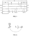
- Figure 1 illustrates the composition of an adhesive tape according to a preferred embodiment of the invention.
- Said adhesive tape comprises a backing layer 1 which is coated on both sides with adhesive layers 2 and 3.
- the one adhesive layer 2 is provided on the lower side of the backing layer 1 and the other adhesive layer 3 is provided on the upper side of the backing layer 1.
- a release liner 6 covers the other adhesive layer 3.
- a cleavage means 4 is provided substantially transverse to at least the backing layer 1.
- the cleavage means 4 shown in Figure 1 is also provided in the adhesive layer 3 and the release liner 6.
- the cleavage means 4 is here realised as a perforation extending transverse to the backing layer 1 and the adhesive layer 3. Said perforation can be made with a flexible dye or a rotary dye.
- the cleavage means 4 is realised as a slit which likewise extends in a transverse direction. Said slit is positioned exactly above the perforation provided in the adhesive layer 3 and the backing layer 1.
- the cleavage means 4 defines the plane along which the adhesive tape is separated into two parts after splicing.
- the breaking strength of the adhesive tape can be fitted to the paper types and the weights involved to ensure a clean splice which in turn ensures a fluent breaking of the tape after effecting the splice, but not during acceleration of the new paper reel.
- cleavage means 4 for example by partially providing slits in the adhesive layer 3 and the backing layer 1 are thinkable.
- the perforation divides the backing layer 1 into a first portion 1a and a second portion 1b.
- the adhesive layer 2 is not effective in the area of the second portion 1b of the backing layer 1 which is realised in the present embodiment by providing the adhesive layer 2 only in the area of the first portion 1a of the back layer 1.
- the other adhesive layer 3 is not effective in the area of the first portion 1a of the backing layer 1 which is realised in the embodiment of Figure 1 by providing the release liner 6 on the adhesive layer 3 at least in the area of the first portion 1a of the backing portion 1.
- the release liner 6 of this embodiment comprises a first portion 6a, a second portion 6b and a third portion 6c.
- the first portion 6a covers the adhesive layer 3 in the area of the backing layer 1a and is therefore provided on the first portion 3a of the adhesive layer 3.
- the second portion 6b and the third portion 6c of the release layer cover the second portion 3b of the adhesive layer 3.
- release liner 6 which separate the first portion 6a, the second portion 6b and the third portion 6c.
- the release liner 6 allows to expose the second portion 3b of the adhesive layer 3 by removing the second portion 6b and the third portion 6c of the release liner 6, as can be seen in Figures 2b and 2c.
- the function of the first portion 6a of the release liner 6 is to prevent that the inner spire of the old paper reel adheres via the other adhesive layer 3 to the part of the adhesive tape which remains on the new reel when breaking the adhesive tape after the splice has been effected.
- the second portion 3b of the adhesive layer 3 comprises a splicing adhesive zone 3c and a reel closing adhesive zone 3d.
- the splicing adhesive zone 3d is located between the reel closing zone 3c and the first portion 3a of the adhesive layer 3.
- the second portion 6b of the release layer covers the splicing adhesive zone 3c and the third portion 6c of the release layer 6 covers the reel closing adhesive zone 3d.
- This arrangement allows to first remove the third portion 6c of the release liner, thereby exposing only the reel closing adhesive zone 3d.
- the second portion 6b of the release liner 6 can be removed to expose the splicing adhesive zone 3c as shown in Figure 2b.
- the thickness of the splicing adhesive zone 3c is in the range of 40 to 100 ⁇ m, preferably 50 to 100 ⁇ m and the thickness of the reel closing adhesive zone 3d is in the range of 40 to 100 ⁇ m, preferably 50 to 100 ⁇ m.
- the splicing adhesive zone 3c and the reel closing adhesive zone 3d have both the same thickness.
- the outer spire of the new reel is adhered to the adhesive layer 3, thereby closing the new reel. This is effected by first removing the third portion 6c of the release liner 6 thereby exposing the reel closing adhesive zone 3d. The outer spire of the new reel is then adhered to the exposed reel closing adhesive zone 3d of the adhesive layer 3. This is effected with sufficient hand pressure to assure a total closure of the new paper reel and without unevenness to avoid air tunnelling. After closure of the new paper reel, the waste paper is removed to assure a straight clean paper edge to avoid flapping of paper during acceleration.
- FIG 3 is a schematic drawing of an embodiment of an apparatus for the measurement of a splicing tack.
- Said apparatus contains an upper disk (A) and a lower disk (B) each having a diameter of 6cm.
- the two disks (A,B) are placed horizontally and centered.
- the upper disk (A) is mounted on a shaft of an electrical motor (M) having a controllable rotating speed.
- the lower disk (B) is connected to a pendulum (P) with a rigid, but free rotating arm of 14cm length and with a mass of 115g.
- the tape to examine is applied to the lower disk (B) with Nitto 500 and Nitto Na-tack n° 144.
- the paper to examine is applied to the upper disk (A) with Nitto 500 and Nitto Na-tack n° 144 (standard: 80g copy paper).
- the upper disk (A) rotates at a given speed, while the lower disk (B) held horizontally at the opposite side, is released.
- connection If the connection is successful, the procedure will be repeated at a speed of 100 rpm higher. Every test is done with fresh tape and paper. The highest speed obtained with a successful splicing is reported.
- a splicing tack level is given to a tape.
- the system is gauged with Nitto R9411 which corresponds to a level 10 and Nitto 5033X which corresponds to a level 5.
Landscapes
- Chemical & Material Sciences (AREA)
- Immunology (AREA)
- Physics & Mathematics (AREA)
- Health & Medical Sciences (AREA)
- Analytical Chemistry (AREA)
- Biochemistry (AREA)
- General Health & Medical Sciences (AREA)
- Life Sciences & Earth Sciences (AREA)
- General Physics & Mathematics (AREA)
- Pathology (AREA)
- Organic Chemistry (AREA)
- Adhesive Tapes (AREA)
- Replacement Of Web Rolls (AREA)
- Storage Of Web-Like Or Filamentary Materials (AREA)
- Adhesives Or Adhesive Processes (AREA)
- Rolls And Other Rotary Bodies (AREA)
- Manufacture Of Motors, Generators (AREA)
Abstract
Description
- The invention relates to an adhesive tape which is used for splicing and closing of reels, in particular paper reels, and a method for changing such reels.
- The conventional practice of closing a new reel, preparing same to be spliced to an old reel and actually conducting the splice is a very intensive and precise action which requires a certain skill, trained people and an amount of time which is not to be neglected. Moreover, said conventional approach is disadvantageous insofar as different types of tapes have to be used. The different tapes have to be repacked individually to maintain their properties. The tapes have to be distinctive and each type has to have its own set of properties. These can be different for the reel closing tape and for the splicing tape.
- Furthermore, difficult cut-out and splice patterns such as "straight cuts, v-shape cuts or asymmetric v-shape cuts" have to be prepared. These splice patterns have to be selected according to the paper grade, the condition of the roll paper weight and the press speed used. These patterns mostly have to be strengthened with labels or tabs to increase the splice-air tightness. These tabs are die cut to break instantly after the splice has been made to release the new roll for unwinding. They are also used to hold down the outer spire during rotation to prevent air pockets being formed, which can burst the splice pattern during acceleration. The number and type of tabs have to be determined by splice speed, paper grade and pattern shape. The tabs should also not be applied too tightly because then they could break in advance. All these tapes and labels have to be positioned very accurately and have to be cut in such a way that an overlap is absolutely avoided. Overlaps can cause air tunnels, which can lead to reopening of the paper reel or may lead to splice failures caused by uneven splice patterns and too thick total splices.
- The present invention concerns an adhesive tape for flying reel changes having a backing layer and adhesive layers coated on both sides of said backing layer. Such an adhesive tape is known from EP 0 831 046 A1.
- EP 0 831 046 A1 further discloses that a readily splitting paper is used for the backing layer so that the backing layer breaks in a longitudinal direction when the reel is opened.
- An adhesive tape of that kind combines the functions of a reel closing tape and a reel splicing tape in such a way that it does not open during acceleration, no air tunnels are formed and the splice is prepared in an easy manner which avoids difficult splice patterns.
- However, a drawback of said known adhesive tape consists in that the splitting force which causes the longitudinal breakage of the backing layer depends on the material of the backing layer and is therefore set to a predetermined value.
- EP 695 709 discloses an adhesive tape for flying reel changes having a backing layer, adhesive layers coated on both sides of said backing layer, a cleavage means provided substantially transverse to said backing layer thereby dividing said backing layer into a first portion and a second portion. EP 555 772 discloses a similar tape without cleavage means, but comprising a protective release layer, i.e. a liner. A release liner is also disclosed in US 5 658 420. The tape according to EP 55 772 is divided in a first portion and a second portion, wherein the one adhesive layer is not effective in the area of the second portion, the other adhesive layer is not effective in the area of the first portion.
- It is an object of the present invention to provide an adhesive tape which allows the control of the splitting force to adapt same to the necessary breaking strength dependable on paper type and weight. It is a further object of the present invention to provide a method for changing a reel, in particular a paper reel, using such an adhesive tape.
- Said object is achieved according to the present invention with respect to the adhesive tape by the subject-matter of claim 1.
- In accordance with the invention, said object is achieved with respect to the method by the subject-matter of claim 21.
- The main advantage of this embodiment consists in that it is possible to remove only the third portion of the release liner for closing the reel while the second portion of the release liner still covers the adhesive layer. The second portion of the release liner is removed only shortly before the splice takes place which facilitates the handling of the adhesive tape.
- One further advantage of the adhesive tape according to the invention consists in that the tape is not restricted to one type of paper quality, but can be adapted by changing the cleavage means, so that the breaking strength can be fitted to the paper types and weights involved to assure a clean splice and hence a fluent breaking of the tape afterwards but not during acceleration of the new reel.
- Another advantage consists in that the usage of different types of tapes and thus the problem of the distinctability and the repacking of the different tapes is avoided. It also implies that less difficult preparations have to be made which means that a straight to almost straight splice can be applied instead of the difficult cut-out and splice patterns normally used.
- A further advantage of the adhesive tape according to the invention is that the thickness of the total splice zone is reduced significantly thus avoiding air tunnels causing reopening and avoiding splice failures caused by uneven splice patterns.
- Preferably, the one adhesive layer is provided only on the first portion of the backing layer. This measure guarantees in an easy manner that the one adhesive layer is effective only in the area of the first portion of the backing layer but not in the area of the second portion of the backing layer.
- Furthermore, it is preferable that the other adhesive layer is provided on the first portion and on the second portion of the backing layer, the release liner covers the other adhesive layer in the area of the first portion and of the second portion of the backing layer, and the cleavage means is provided in the other adhesive layer thereby dividing said adhesive layer in a first and a second portion. This preferred embodiment of the invention guarantees that the other adhesive layer is effective only in the area of the second portion of the backing layer but not in the area of the first portion of the backing layer.
- According to a further preferred embodiment, the cleavage means is in addition to the slit, provided in the release liner thereby dividing the release liner in a first, a second and a third portion, the first portion being located in the area of the first portion of the backing layer.
- In a further improved embodiment of the invention, the second portion of the adhesive layer comprises a splicing adhesive zone and a reel closing adhesive zone, the splicing adhesive zone being located between the reel closing adhesive zone and the first portion of the adhesive layer, wherein the thickness of the splicing adhesive zone and the thickness of the reel closing adhesive zone are in a range of 40 to 100 µm, preferably 50 to 100 µm. The thickness of the splicing adhesive zone can be equal to the thickness of the reel closing adhesive zone.
- Preferably, the cleavage means is a perforation which can easily be changed to control the splitting force necessary for breaking the tape. The cleavage means provided in the release liner can be a slit.
- The width W of the tape can be in the range of 40 mm to 100 mm. The width W1 of the first portions of the backing layer, the adhesive layer and the release liner can be in the range of 6 mm to 20 mm, preferably in the range of 10 mm to 20 mm. The width W1 of the one adhesive layer can be in a range of 6 mm to 20 mm, preferably in the range of 10 mm to 20 mm. The width W2 of the third portion of the release liner (6) can be in the range of 6 mm to 20 mm, preferably in the range of 10 mm to 20 mm.
- The tear strength of the adhesive tape can be in the range of 10 to 30 kg/m. The total product can be repulpable or non-repulpable. The backing layer can be made of a perforated paper backing or film. The paper backing weight can be in the range of 40 to 100 g/m2. The film can be a PVC with a thickness of 12 to 75 µm or a PET with a thickness of 12 to 50 µm or an oriented PP with a thickness of 25 to 75 µm or a non-woven type with a grammage of 10 to 25 g/m2 or an aluminum based film with a thickness of 12 to 75 µm. The release liner can have a release value being not lower than 10 cN/50 mm and not more than 100 cN/50 mm.
- A preferred embodiment of the method according to the invention comprises the steps of
- Removing the third portion of the release liner thereby exposing the reel closing adhesive zone;
- Adhering the outer spire of the new reel to the reel closing adhesive zone thereby closing the reel;
- Removing the waste paper in order to provide a straight clean paper edge; and further the steps
- Removing the second portion of the release liner shortly before the splicing is effected thereby exposing the splicing adhesive zone; and
- Adhering the (almost) inner spire of the old reel to the splicing adhesive zone of the adhesive layer.
- The invention will now be described by way of example and with reference to the accompanying drawings in which:
- Figure 1 is a cross section of the adhesive tape according to an embodiment of the invention;
- Figure 2A shows a new paper reel which is closed with the adhesive tape according to the embodiment of the invention,
- Figure 2B shows the closed new paper reel and the adhesive tape according to the embodiment of the invention which is prepared for splicing,
- Figure 2C shows the new paper reel during the splicing of its outer spire with the (almost) inner spire of an old paper reel;
- Figure 2D shows the new paper reel after the splice has taken place; and
- Figure 3 is a schematic illustration of an apparatus for the measurement of a splicing tack.
-
- Figure 1 illustrates the composition of an adhesive tape according to a preferred embodiment of the invention. Said adhesive tape comprises a backing layer 1 which is coated on both sides with adhesive layers 2 and 3. In the embodiment shown in Figure 1, the one adhesive layer 2 is provided on the lower side of the backing layer 1 and the other adhesive layer 3 is provided on the upper side of the backing layer 1. A
release liner 6 covers the other adhesive layer 3. - It is seen in Figure 1 that a cleavage means 4 is provided substantially transverse to at least the backing layer 1. The cleavage means 4 shown in Figure 1 is also provided in the adhesive layer 3 and the
release liner 6. The cleavage means 4 is here realised as a perforation extending transverse to the backing layer 1 and the adhesive layer 3. Said perforation can be made with a flexible dye or a rotary dye. In therelease liner 6, the cleavage means 4 is realised as a slit which likewise extends in a transverse direction. Said slit is positioned exactly above the perforation provided in the adhesive layer 3 and the backing layer 1. - The cleavage means 4 defines the plane along which the adhesive tape is separated into two parts after splicing. By changing the perforation widths and distances, the breaking strength of the adhesive tape can be fitted to the paper types and the weights involved to ensure a clean splice which in turn ensures a fluent breaking of the tape after effecting the splice, but not during acceleration of the new paper reel.
- Other ways to realise the cleavage means 4 for example by partially providing slits in the adhesive layer 3 and the backing layer 1 are thinkable.
- It is further shown in Figure 1 that the perforation divides the backing layer 1 into a
first portion 1a and asecond portion 1b. It can further be seen that the adhesive layer 2 is not effective in the area of thesecond portion 1b of the backing layer 1 which is realised in the present embodiment by providing the adhesive layer 2 only in the area of thefirst portion 1a of the back layer 1. The other adhesive layer 3 is not effective in the area of thefirst portion 1a of the backing layer 1 which is realised in the embodiment of Figure 1 by providing therelease liner 6 on the adhesive layer 3 at least in the area of thefirst portion 1a of the backing portion 1. - The
release liner 6 of this embodiment comprises afirst portion 6a, asecond portion 6b and athird portion 6c. Thefirst portion 6a covers the adhesive layer 3 in the area of thebacking layer 1a and is therefore provided on thefirst portion 3a of the adhesive layer 3. - The
second portion 6b and thethird portion 6c of the release layer cover thesecond portion 3b of the adhesive layer 3. - Furthermore, two slits are provided in the
release liner 6 which separate thefirst portion 6a, thesecond portion 6b and thethird portion 6c. Therelease liner 6 allows to expose thesecond portion 3b of the adhesive layer 3 by removing thesecond portion 6b and thethird portion 6c of therelease liner 6, as can be seen in Figures 2b and 2c. - As shown in Figures 2c and 2d, the function of the
first portion 6a of therelease liner 6 is to prevent that the inner spire of the old paper reel adheres via the other adhesive layer 3 to the part of the adhesive tape which remains on the new reel when breaking the adhesive tape after the splice has been effected. - The measure to provide the one adhesive layer 2 only in the area of the
first portion 1 a of the backing layer 1 and hence in this part of the adhesive tape which remains on the new reel allows the separation of the other part of the adhesive tape which is responsible for the splice. This can be seen in Figure 2b. - Other ways to prevent that the one adhesive layer 2 is not effective in the area of the
second portion 1b and the other adhesive layer 3 is not effective in the area of thefirst portion 1a of the backing layer are likewise thinkable. The other adhesive layer 3 could for example be provided only in the area of thesecond portion 1b of the backing layer. - The
second portion 3b of the adhesive layer 3 comprises asplicing adhesive zone 3c and a reelclosing adhesive zone 3d. As can be seen in Figure 1, thesplicing adhesive zone 3d is located between thereel closing zone 3c and thefirst portion 3a of the adhesive layer 3. Furthermore it can be seen in Figure 1 that thesecond portion 6b of the release layer covers thesplicing adhesive zone 3c and thethird portion 6c of therelease layer 6 covers the reel closingadhesive zone 3d. This arrangement allows to first remove thethird portion 6c of the release liner, thereby exposing only the reel closingadhesive zone 3d. This is shown in Figure 2a. Thesecond portion 6b of therelease liner 6 can be removed to expose thesplicing adhesive zone 3c as shown in Figure 2b. The thickness of thesplicing adhesive zone 3c is in the range of 40 to 100 µm, preferably 50 to 100µm and the thickness of the reel closingadhesive zone 3d is in the range of 40 to 100 µm, preferably 50 to 100µm. - The
splicing adhesive zone 3c and the reel closingadhesive zone 3d have both the same thickness. - In the following, a method for changing a reel, in particular a paper reel, according to an embodiment of the invention is described with reference to Figures 2a, 2b, 2c and 2d.
- In Figure 2a it is shown that the adhesive tape is adhered with the adhesive layer 2 to the new wheel which is to be spliced. The adhesive layer 2 is automatically exposed while unwinding the adhesive tape.
- Then the outer spire of the new reel is adhered to the adhesive layer 3, thereby closing the new reel. This is effected by first removing the
third portion 6c of therelease liner 6 thereby exposing the reel closingadhesive zone 3d. The outer spire of the new reel is then adhered to the exposed reel closingadhesive zone 3d of the adhesive layer 3. This is effected with sufficient hand pressure to assure a total closure of the new paper reel and without unevenness to avoid air tunnelling. After closure of the new paper reel, the waste paper is removed to assure a straight clean paper edge to avoid flapping of paper during acceleration. - Then the inner spire of the old reel is adhered to the adhesive layer 3. This is effected, as can be seen in Figure 2b by first removing the
second portion 6b of therelease liner 6 shortly before the splicing is effected, thereby exposing thesplicing adhesive zone 3c. Then the new paper reel is brought to the same speed as the old paper reel. The splice is then being made between the inner paper winding of the old reel and the outer spire of the new reel, shown in Figure 2c. After the cleavage has occurred along the perforation or cleavage means 4, one part of the adhesive tape remains on the new reel and the other part adheres to the inner and outer spire of the old and new reel. This is shown in Figure 2d. - Although the present invention is described in connection with paper reels, the use of the adhesive tape for related reels is likewise thinkable.
- Figure 3 is a schematic drawing of an embodiment of an apparatus for the measurement of a splicing tack. Said apparatus contains an upper disk (A) and a lower disk (B) each having a diameter of 6cm. The two disks (A,B) are placed horizontally and centered. The upper disk (A) is mounted on a shaft of an electrical motor (M) having a controllable rotating speed. The lower disk (B) is connected to a pendulum (P) with a rigid, but free rotating arm of 14cm length and with a mass of 115g.
- The tape to examine is applied to the lower disk (B) with Nitto 500 and Nitto Na-tack n° 144. The paper to examine is applied to the upper disk (A) with Nitto 500 and Nitto Na-tack n° 144 (standard: 80g copy paper).
- The upper disk (A) rotates at a given speed, while the lower disk (B) held horizontally at the opposite side, is released.
- If the connection is successful, the procedure will be repeated at a speed of 100 rpm higher. Every test is done with fresh tape and paper. The highest speed obtained with a successful splicing is reported.
- A splicing tack level is given to a tape. The system is gauged with Nitto R9411 which corresponds to a
level 10 and Nitto 5033X which corresponds to a level 5.
Claims (22)
- An adhesive tape for flying reel changes having a backing layer (1), adhesive layers (2, 3) coated on both sides of said backing layer (1), a release liner (6) covering one of the adhesive layers (2,3) and a cleavage means (4) provided substantially transverse to at least said backing layer (1), thereby dividing said backing layer (1) into a first portion (1a) and a second portion (1b), wherein the one adhesive layer (2) is not effective in the area of the second portion (1b), the other adhesive layer (3) is not effective in the area of the first portion (1a) of the backing layer (1) and wherein a slit (7) is provided in the release liner (6) in the area of the second portion (1b) of the backing layer (1), so that it is possible to remove one portion of the release liner (6).
- The adhesive tape according to claim 1, wherein the one adhesive layer (2) is provided only on the first portion (1a) of the backing layer (1).
- The adhesive tape according to claim 1 or 2, whereinthe other adhesive layer (3) is provided on the first portion (1a) and on the second portion (1b) of the backing layer (1);the release liner (6) covers the other adhesive layer (3) in the area of the first portion (1a) and of the second portion (1b) of the backing layer (1); andthe cleavage means (4) is provided in the other adhesive layer (3) thereby dividing said adhesive layer (3) in a first portion (3a) and a second portion (3b).
- The adhesive tape according to claim 3, wherein
the cleavage means (4) is in addition to the slit (7), provided in the release liner (6) thereby dividing the release liner (6) in a first, a second and a third portion (6a,6b,6c), the first portion (6a) being located in the area of the first portion (1a) of the backing layer (1). - The adhesive tape according to claim 4, wherein the second portion (3b) of the adhesive layer (3) comprises a splicing adhesive zone (3c) and a reel closing adhesive zone (3d), the splicing adhesive zone (3c) being located between the reel closing zone (3d) and the first portion (3a) of the adhesive layer (3), wherein the thickness of the splicing adhesive zone (3c) and the thickness of the reel closing adhesive zone (3d) are in a range of 40 to 100 µm.
- The adhesive tape according to claim 5, wherein the thickness of the splicing adhesive zone (3c) is equal to the thickness of the reel closing adhesive zone (3d).
- The adhesive tape according to at least one of the foregoing claims, wherein the cleavage means (4) is a perforation.
- The adhesive tape according to at least one of the foregoing claims, wherein the cleavage means (4) provided in the release liner (6) is a slit.
- The adhesive tape according to at least one of the foregoing claims, wherein the width W of the tape is in a range of 40 mm to 100 mm.
- The adhesive tape according to at least one of the foregoing claims, wherein the width W1 of the first portions (1a, 3a, 6a) is in a range of 6 mm to 20 mm.
- The adhesive tape according to at least one of the foregoing claims, wherein the width W1 of the adhesive layer (2) is in a range of 6 mm to 20 mm.
- The adhesive tape according to at least one of the foregoing claims, wherein the widths W2 of the third portion (6c) of the release liner (6) is in a range of 6 mm to 20 mm.
- The adhesive tape according to at least one of the foregoing claims, wherein the tear strength of said tape is in a range of 10 to 30 kg/m.
- The adhesive tape according to at least one of the foregoing claims, wherein the total product is repulpable.
- The adhesive tape according to at least one of the foregoing claims 1 to 13, wherein the total product is not repulpable.
- The adhesive tape according to at least one of the foregoing claims, wherein the backing layer (1) is made of a perforated paper backing or film.
- The adhesive tape according to claim 16, wherein the weight of the paper backing (1) is in a range of 40 to 100 g/m2.
- The adhesive tape according to claim 16, wherein the film isa PVC with a thickness of 12 to 75 µm ora PET with a thickness of 12 to 50 µm oran oriented PP with a thickness of 25 to 75 µm; ora non-woven type with a grammage of 10 to 25 g/m2 oran aluminum based film with a thickness of 12 to 75 µm.
- The adhesive tape according to at least one of claims 3 to 18, wherein the release liner (6) has a release value being not lower than 10 cN/50 mm and not more than 100 cN/50 mm.
- The adhesive tape according to any of claims 1, 2, 5-7 and 8-19, wherein the other adhesive layer (3) is provided only on the second portion (1b) of the backing layer (1).
- A method for changing a reel, in particular a paper reel, comprising the steps:a) adhering an adhesive tape according to at least one of claims 1 to 20 with the adhesive layer (2) to the new reel to be spliced;b) adhering the outer spire of the new reel to the adhesive layer (3) thereby closing the new reel;c) adhering the inner spire of the old reel to the adhesive layer (3).
- The method according to claim 21, wherein step b) comprises the steps:wherein step c) comprises the steps:b1) removing the third portion (6c) of the release liner (6) thereby exposing the reel closing adhesive zone (3d);b2) adhering the outer spire of the new reel to the reel closing adhesive zone (3d) of the adhesive layer (3);b3) removing the waste paper in order to provide a straight, clean paper edge; andc1) removing the second portion (6b) of the release liner (6) shortly before the splicing is effected thereby exposing the splicing adhesive zone (3c); andc2) adhering the (almost) inner spire of the old reel to the splicing adhesive zone (3c) of the adhesive layer (3).
Priority Applications (1)
| Application Number | Priority Date | Filing Date | Title |
|---|---|---|---|
| EP02706704A EP1377511B1 (en) | 2001-01-16 | 2002-01-14 | Adhesive tape for flying reel changes |
Applications Claiming Priority (4)
| Application Number | Priority Date | Filing Date | Title |
|---|---|---|---|
| EP01100908A EP1223133A1 (en) | 2001-01-16 | 2001-01-16 | Adhesive tape for flying reel changes |
| EP01100908 | 2001-01-16 | ||
| PCT/EP2002/000293 WO2002055419A2 (en) | 2001-01-16 | 2002-01-14 | Adhesive tape for flying reel changes |
| EP02706704A EP1377511B1 (en) | 2001-01-16 | 2002-01-14 | Adhesive tape for flying reel changes |
Publications (2)
| Publication Number | Publication Date |
|---|---|
| EP1377511A2 EP1377511A2 (en) | 2004-01-07 |
| EP1377511B1 true EP1377511B1 (en) | 2005-02-09 |
Family
ID=8176221
Family Applications (2)
| Application Number | Title | Priority Date | Filing Date |
|---|---|---|---|
| EP01100908A Withdrawn EP1223133A1 (en) | 2001-01-16 | 2001-01-16 | Adhesive tape for flying reel changes |
| EP02706704A Expired - Lifetime EP1377511B1 (en) | 2001-01-16 | 2002-01-14 | Adhesive tape for flying reel changes |
Family Applications Before (1)
| Application Number | Title | Priority Date | Filing Date |
|---|---|---|---|
| EP01100908A Withdrawn EP1223133A1 (en) | 2001-01-16 | 2001-01-16 | Adhesive tape for flying reel changes |
Country Status (19)
| Country | Link |
|---|---|
| US (1) | US20040075014A1 (en) |
| EP (2) | EP1223133A1 (en) |
| JP (1) | JP2004526815A (en) |
| CN (1) | CN1492828A (en) |
| AT (1) | ATE288868T1 (en) |
| AU (1) | AU2002240900B9 (en) |
| BG (1) | BG108088A (en) |
| BR (1) | BR0206474A (en) |
| CA (1) | CA2434301A1 (en) |
| DE (1) | DE60202939T2 (en) |
| DK (1) | DK1377511T3 (en) |
| ES (1) | ES2236488T3 (en) |
| HU (1) | HUP0501022A2 (en) |
| MX (1) | MXPA03006202A (en) |
| PL (1) | PL368446A1 (en) |
| PT (1) | PT1377511E (en) |
| RU (1) | RU2235669C1 (en) |
| WO (1) | WO2002055419A2 (en) |
| ZA (1) | ZA200305322B (en) |
Families Citing this family (11)
| Publication number | Priority date | Publication date | Assignee | Title |
|---|---|---|---|---|
| US6899933B2 (en) | 2002-09-09 | 2005-05-31 | Permacel | Splicing tape with separating portions |
| US7476429B2 (en) | 2003-11-03 | 2009-01-13 | Permacel | Bridge label for splicing tape |
| DE102004040814A1 (en) * | 2004-08-24 | 2006-03-02 | Tesa Ag | Adhesive tape for making a splice connection |
| DE102005061104B4 (en) * | 2005-12-21 | 2008-02-21 | Vits Systems Gmbh | Adhesive tape for a flying reel change |
| DE102006053439A1 (en) * | 2006-02-22 | 2008-05-15 | Tesa Ag | Adhesive tape and its use |
| RU2476472C2 (en) * | 2011-11-02 | 2013-02-27 | Владимир Алексеевич Небольсин | Rolled adhesive tape |
| RU2727208C9 (en) * | 2016-12-12 | 2020-09-02 | Алексей Анатольевич Алексеев | Three-layer tape and its manufacturing method |
| RU193815U1 (en) * | 2019-03-25 | 2019-11-15 | Общество с ограниченной ответственностью "Биком" | Single-sided tape for packing packs of glass |
| DE102019220424A1 (en) | 2019-12-20 | 2021-06-24 | Tesa Se | Adhesive suitable for the flying roll change of materials with low-energy surfaces |
| WO2025105984A1 (en) * | 2023-11-14 | 2025-05-22 | Павел Сергеевич РОЗОВ | Self-adhesive abrasive belt |
| CN120590874A (en) * | 2025-06-19 | 2025-09-05 | 惠州市隆合科技有限公司 | Composite tape and method of use thereof |
Family Cites Families (11)
| Publication number | Priority date | Publication date | Assignee | Title |
|---|---|---|---|---|
| US3124955A (en) * | 1964-03-17 | Method and means for determining adherence | ||
| US2377971A (en) * | 1943-12-15 | 1945-06-12 | Wood Newspaper Mach Corp | Means for use in splicing webs |
| US3547739A (en) * | 1969-05-15 | 1970-12-15 | Harvey N Beute | Perforated tape |
| GB1504286A (en) * | 1975-05-22 | 1978-03-15 | Norprint Ltd | Adhesive tabs |
| JP3046445B2 (en) * | 1992-02-10 | 2000-05-29 | 日東電工株式会社 | Water soluble double sided tape for splicing |
| DE4219968C2 (en) * | 1992-06-19 | 1994-04-14 | Koenig & Bauer Ag | Adhesive tip for paper rolls |
| DE4423387C2 (en) * | 1994-07-04 | 1996-06-20 | Koenig & Bauer Albert Ag | Adhesive tape for attaching a paper web start of a stock paper web roll |
| WO1996002450A2 (en) * | 1994-07-20 | 1996-02-01 | Minnesota Mining And Manufacturing Company | Apparatus for applying adhesive tape |
| RU2074875C1 (en) * | 1996-06-18 | 1997-03-10 | Игорь Анатольевич Рожков | Method for production of thermoshrinkable multilayer adhesive band |
| DE19632689A1 (en) * | 1996-08-14 | 1998-02-19 | Beiersdorf Ag | Adhesive tape and method of using it |
| DE19902179B4 (en) * | 1999-01-21 | 2005-04-28 | Tesa Ag | Adhesive tape and splice process |
-
2001
- 2001-01-16 EP EP01100908A patent/EP1223133A1/en not_active Withdrawn
-
2002
- 2002-01-14 CA CA002434301A patent/CA2434301A1/en not_active Abandoned
- 2002-01-14 JP JP2002556108A patent/JP2004526815A/en not_active Withdrawn
- 2002-01-14 AT AT02706704T patent/ATE288868T1/en not_active IP Right Cessation
- 2002-01-14 HU HU0501022A patent/HUP0501022A2/en unknown
- 2002-01-14 PL PL02368446A patent/PL368446A1/en unknown
- 2002-01-14 ES ES02706704T patent/ES2236488T3/en not_active Expired - Lifetime
- 2002-01-14 BR BR0206474-0A patent/BR0206474A/en not_active IP Right Cessation
- 2002-01-14 RU RU2003124081/12A patent/RU2235669C1/en not_active IP Right Cessation
- 2002-01-14 DE DE60202939T patent/DE60202939T2/en not_active Expired - Fee Related
- 2002-01-14 EP EP02706704A patent/EP1377511B1/en not_active Expired - Lifetime
- 2002-01-14 US US10/466,279 patent/US20040075014A1/en not_active Abandoned
- 2002-01-14 MX MXPA03006202A patent/MXPA03006202A/en unknown
- 2002-01-14 CN CNA028037839A patent/CN1492828A/en active Pending
- 2002-01-14 DK DK02706704T patent/DK1377511T3/en active
- 2002-01-14 WO PCT/EP2002/000293 patent/WO2002055419A2/en not_active Ceased
- 2002-01-14 AU AU2002240900A patent/AU2002240900B9/en not_active Ceased
- 2002-01-14 PT PT02706704T patent/PT1377511E/en unknown
-
2003
- 2003-07-09 ZA ZA200305322A patent/ZA200305322B/en unknown
- 2003-08-13 BG BG108088A patent/BG108088A/en unknown
Also Published As
| Publication number | Publication date |
|---|---|
| DK1377511T3 (en) | 2005-05-23 |
| US20040075014A1 (en) | 2004-04-22 |
| EP1223133A1 (en) | 2002-07-17 |
| CN1492828A (en) | 2004-04-28 |
| PL368446A1 (en) | 2005-03-21 |
| BR0206474A (en) | 2003-12-30 |
| ATE288868T1 (en) | 2005-02-15 |
| ZA200305322B (en) | 2004-08-30 |
| WO2002055419A3 (en) | 2003-10-23 |
| CA2434301A1 (en) | 2002-07-18 |
| AU2002240900B9 (en) | 2005-04-14 |
| HUP0501022A2 (en) | 2008-10-28 |
| EP1377511A2 (en) | 2004-01-07 |
| BG108088A (en) | 2004-12-30 |
| AU2002240900B2 (en) | 2004-11-11 |
| ES2236488T3 (en) | 2005-07-16 |
| WO2002055419A2 (en) | 2002-07-18 |
| RU2235669C1 (en) | 2004-09-10 |
| DE60202939T2 (en) | 2005-07-07 |
| DE60202939D1 (en) | 2005-03-17 |
| JP2004526815A (en) | 2004-09-02 |
| MXPA03006202A (en) | 2004-12-03 |
| PT1377511E (en) | 2005-04-29 |
Similar Documents
| Publication | Publication Date | Title |
|---|---|---|
| US5323981A (en) | Splicer tape system | |
| US5916651A (en) | Adhesive tape and method of using it | |
| AU2002240900B9 (en) | Adhesive tape for flying reel changes | |
| US7766273B2 (en) | Method for cutting and spooling a paper web | |
| GB2161420A (en) | Procedure for joining the pulling end of a first web to the pulled end of a second web and equipment therefor | |
| CA2025473A1 (en) | Method of pre-treating a renewal web rolled on a roll for adhesion to a previously used web, particularly paper web for use in printing machines, and renewal web adhesion system | |
| US8080300B2 (en) | Tape roll tab application method and article | |
| AU2002240900A1 (en) | Adhesive tape for flying reel changes | |
| JPH0346951A (en) | Adhesive tape | |
| JP4666911B2 (en) | Adhesive tape that can be detected by machine | |
| WO2003008311A1 (en) | High-speed web-splicing tape and method of use thereof | |
| US20030010422A1 (en) | High-speed web-splicing tape and method of use thereof | |
| AU687429B2 (en) | Flying splice adhesive tape | |
| US10815092B2 (en) | Dispenser cartridge and wiper | |
| CA2303706C (en) | Method of preparing for a splice | |
| CA2511994C (en) | Adhesive tape for producing a splice | |
| US11046541B2 (en) | Dispenser cartridge and wiper with cord | |
| JP2862660B2 (en) | How to prevent the paper edge from peeling off the web | |
| JP2004202593A (en) | Slitter for flexible packaging materials | |
| GB2335913A (en) | Adhesive tab for securing a web roll | |
| JPH10114452A (en) | Tape to prevent unraveling of paper edge |
Legal Events
| Date | Code | Title | Description |
|---|---|---|---|
| PUAI | Public reference made under article 153(3) epc to a published international application that has entered the european phase |
Free format text: ORIGINAL CODE: 0009012 |
|
| 17P | Request for examination filed |
Effective date: 20030813 |
|
| AK | Designated contracting states |
Kind code of ref document: A2 Designated state(s): AT BE CH CY DE DK ES FI FR GB GR IE IT LI LU MC NL PT SE TR |
|
| AX | Request for extension of the european patent |
Extension state: AL LT LV MK RO SI |
|
| GRAP | Despatch of communication of intention to grant a patent |
Free format text: ORIGINAL CODE: EPIDOSNIGR1 |
|
| GRAS | Grant fee paid |
Free format text: ORIGINAL CODE: EPIDOSNIGR3 |
|
| REG | Reference to a national code |
Ref country code: HK Ref legal event code: DE Ref document number: 1063175 Country of ref document: HK |
|
| GRAA | (expected) grant |
Free format text: ORIGINAL CODE: 0009210 |
|
| AK | Designated contracting states |
Kind code of ref document: B1 Designated state(s): AT BE CH CY DE DK ES FI FR GB GR IE IT LI LU MC NL PT SE TR |
|
| PG25 | Lapsed in a contracting state [announced via postgrant information from national office to epo] |
Ref country code: IT Free format text: LAPSE BECAUSE OF FAILURE TO SUBMIT A TRANSLATION OF THE DESCRIPTION OR TO PAY THE FEE WITHIN THE PRESCRIBED TIME-LIMIT;WARNING: LAPSES OF ITALIAN PATENTS WITH EFFECTIVE DATE BEFORE 2007 MAY HAVE OCCURRED AT ANY TIME BEFORE 2007. THE CORRECT EFFECTIVE DATE MAY BE DIFFERENT FROM THE ONE RECORDED. Effective date: 20050209 Ref country code: NL Free format text: LAPSE BECAUSE OF FAILURE TO SUBMIT A TRANSLATION OF THE DESCRIPTION OR TO PAY THE FEE WITHIN THE PRESCRIBED TIME-LIMIT Effective date: 20050209 |
|
| REG | Reference to a national code |
Ref country code: GB Ref legal event code: FG4D |
|
| REG | Reference to a national code |
Ref country code: CH Ref legal event code: EP Ref country code: CH Ref legal event code: NV Representative=s name: PATENTANWALTSBUERO JEAN HUNZIKER |
|
| REG | Reference to a national code |
Ref country code: IE Ref legal event code: FG4D |
|
| REF | Corresponds to: |
Ref document number: 60202939 Country of ref document: DE Date of ref document: 20050317 Kind code of ref document: P |
|
| REG | Reference to a national code |
Ref country code: GR Ref legal event code: EP Ref document number: 20050400877 Country of ref document: GR |
|
| REG | Reference to a national code |
Ref country code: PT Ref legal event code: SC4A Free format text: AVAILABILITY OF NATIONAL TRANSLATION Effective date: 20050225 |
|
| PG25 | Lapsed in a contracting state [announced via postgrant information from national office to epo] |
Ref country code: SE Free format text: LAPSE BECAUSE OF FAILURE TO SUBMIT A TRANSLATION OF THE DESCRIPTION OR TO PAY THE FEE WITHIN THE PRESCRIBED TIME-LIMIT Effective date: 20050509 |
|
| REG | Reference to a national code |
Ref country code: DK Ref legal event code: T3 |
|
| REG | Reference to a national code |
Ref country code: ES Ref legal event code: FG2A Ref document number: 2236488 Country of ref document: ES Kind code of ref document: T3 |
|
| NLV1 | Nl: lapsed or annulled due to failure to fulfill the requirements of art. 29p and 29m of the patents act | ||
| REG | Reference to a national code |
Ref country code: HK Ref legal event code: WD Ref document number: 1063175 Country of ref document: HK |
|
| PLBE | No opposition filed within time limit |
Free format text: ORIGINAL CODE: 0009261 |
|
| STAA | Information on the status of an ep patent application or granted ep patent |
Free format text: STATUS: NO OPPOSITION FILED WITHIN TIME LIMIT |
|
| ET | Fr: translation filed | ||
| PG25 | Lapsed in a contracting state [announced via postgrant information from national office to epo] |
Ref country code: GB Free format text: LAPSE BECAUSE OF NON-PAYMENT OF DUE FEES Effective date: 20060114 Ref country code: FI Free format text: LAPSE BECAUSE OF NON-PAYMENT OF DUE FEES Effective date: 20060114 Ref country code: AT Free format text: LAPSE BECAUSE OF NON-PAYMENT OF DUE FEES Effective date: 20060114 |
|
| PG25 | Lapsed in a contracting state [announced via postgrant information from national office to epo] |
Ref country code: ES Free format text: LAPSE BECAUSE OF NON-PAYMENT OF DUE FEES Effective date: 20060116 Ref country code: IE Free format text: LAPSE BECAUSE OF NON-PAYMENT OF DUE FEES Effective date: 20060116 |
|
| PG25 | Lapsed in a contracting state [announced via postgrant information from national office to epo] |
Ref country code: LI Free format text: LAPSE BECAUSE OF NON-PAYMENT OF DUE FEES Effective date: 20060131 Ref country code: BE Free format text: LAPSE BECAUSE OF NON-PAYMENT OF DUE FEES Effective date: 20060131 Ref country code: FR Free format text: LAPSE BECAUSE OF NON-PAYMENT OF DUE FEES Effective date: 20060131 Ref country code: DK Free format text: LAPSE BECAUSE OF NON-PAYMENT OF DUE FEES Effective date: 20060131 Ref country code: MC Free format text: LAPSE BECAUSE OF NON-PAYMENT OF DUE FEES Effective date: 20060131 Ref country code: CH Free format text: LAPSE BECAUSE OF NON-PAYMENT OF DUE FEES Effective date: 20060131 Ref country code: LU Free format text: LAPSE BECAUSE OF NON-PAYMENT OF DUE FEES Effective date: 20060131 |
|
| 26N | No opposition filed |
Effective date: 20051110 |
|
| PG25 | Lapsed in a contracting state [announced via postgrant information from national office to epo] |
Ref country code: DE Free format text: LAPSE BECAUSE OF NON-PAYMENT OF DUE FEES Effective date: 20060801 |
|
| REG | Reference to a national code |
Ref country code: DK Ref legal event code: EBP |
|
| REG | Reference to a national code |
Ref country code: CH Ref legal event code: PL |
|
| GBPC | Gb: european patent ceased through non-payment of renewal fee |
Effective date: 20060114 |
|
| PG25 | Lapsed in a contracting state [announced via postgrant information from national office to epo] |
Ref country code: PT Free format text: LAPSE BECAUSE OF NON-PAYMENT OF DUE FEES Effective date: 20061016 |
|
| REG | Reference to a national code |
Ref country code: IE Ref legal event code: MM4A |
|
| REG | Reference to a national code |
Ref country code: FR Ref legal event code: ST Effective date: 20060929 |
|
| REG | Reference to a national code |
Ref country code: PT Ref legal event code: MM4A Free format text: LAPSE DUE TO NON-PAYMENT OF FEES Effective date: 20061016 |
|
| REG | Reference to a national code |
Ref country code: ES Ref legal event code: FD2A Effective date: 20060116 |
|
| BERE | Be: lapsed |
Owner name: *NITTO EUROPE N.V. Effective date: 20060131 |
|
| PG25 | Lapsed in a contracting state [announced via postgrant information from national office to epo] |
Ref country code: GR Free format text: LAPSE BECAUSE OF NON-PAYMENT OF DUE FEES Effective date: 20060802 |
|
| PG25 | Lapsed in a contracting state [announced via postgrant information from national office to epo] |
Ref country code: CY Free format text: LAPSE BECAUSE OF FAILURE TO SUBMIT A TRANSLATION OF THE DESCRIPTION OR TO PAY THE FEE WITHIN THE PRESCRIBED TIME-LIMIT Effective date: 20050209 |
|
| PG25 | Lapsed in a contracting state [announced via postgrant information from national office to epo] |
Ref country code: TR Free format text: LAPSE BECAUSE OF FAILURE TO SUBMIT A TRANSLATION OF THE DESCRIPTION OR TO PAY THE FEE WITHIN THE PRESCRIBED TIME-LIMIT Effective date: 20050209 |