EP1377464B1 - Pneumatic tire with reinforced bead part - Google Patents
Pneumatic tire with reinforced bead part Download PDFInfo
- Publication number
- EP1377464B1 EP1377464B1 EP01963601A EP01963601A EP1377464B1 EP 1377464 B1 EP1377464 B1 EP 1377464B1 EP 01963601 A EP01963601 A EP 01963601A EP 01963601 A EP01963601 A EP 01963601A EP 1377464 B1 EP1377464 B1 EP 1377464B1
- Authority
- EP
- European Patent Office
- Prior art keywords
- bead
- carcass ply
- rubber lump
- tire
- lump
- Prior art date
- Legal status (The legal status is an assumption and is not a legal conclusion. Google has not performed a legal analysis and makes no representation as to the accuracy of the status listed.)
- Expired - Lifetime
Links
- 239000011324 bead Substances 0.000 title claims abstract description 79
- 230000002787 reinforcement Effects 0.000 abstract 1
- 238000004804 winding Methods 0.000 description 5
- 230000003014 reinforcing effect Effects 0.000 description 4
- 238000004519 manufacturing process Methods 0.000 description 2
- 238000000034 method Methods 0.000 description 2
- 238000000465 moulding Methods 0.000 description 1
Images


Classifications
-
- B—PERFORMING OPERATIONS; TRANSPORTING
- B60—VEHICLES IN GENERAL
- B60C—VEHICLE TYRES; TYRE INFLATION; TYRE CHANGING; CONNECTING VALVES TO INFLATABLE ELASTIC BODIES IN GENERAL; DEVICES OR ARRANGEMENTS RELATED TO TYRES
- B60C9/00—Reinforcements or ply arrangement of pneumatic tyres
- B60C9/02—Carcasses
-
- B—PERFORMING OPERATIONS; TRANSPORTING
- B60—VEHICLES IN GENERAL
- B60C—VEHICLE TYRES; TYRE INFLATION; TYRE CHANGING; CONNECTING VALVES TO INFLATABLE ELASTIC BODIES IN GENERAL; DEVICES OR ARRANGEMENTS RELATED TO TYRES
- B60C15/00—Tyre beads, e.g. ply turn-up or overlap
-
- B—PERFORMING OPERATIONS; TRANSPORTING
- B60—VEHICLES IN GENERAL
- B60C—VEHICLE TYRES; TYRE INFLATION; TYRE CHANGING; CONNECTING VALVES TO INFLATABLE ELASTIC BODIES IN GENERAL; DEVICES OR ARRANGEMENTS RELATED TO TYRES
- B60C15/00—Tyre beads, e.g. ply turn-up or overlap
- B60C15/0009—Tyre beads, e.g. ply turn-up or overlap features of the carcass terminal portion
- B60C15/0081—Tyre beads, e.g. ply turn-up or overlap features of the carcass terminal portion the carcass plies folded around or between more than one bead core
-
- B—PERFORMING OPERATIONS; TRANSPORTING
- B60—VEHICLES IN GENERAL
- B60C—VEHICLE TYRES; TYRE INFLATION; TYRE CHANGING; CONNECTING VALVES TO INFLATABLE ELASTIC BODIES IN GENERAL; DEVICES OR ARRANGEMENTS RELATED TO TYRES
- B60C15/00—Tyre beads, e.g. ply turn-up or overlap
- B60C15/02—Seating or securing beads on rims
- B60C15/024—Bead contour, e.g. lips, grooves, or ribs
- B60C15/0247—Bead contour, e.g. lips, grooves, or ribs with reverse bead seat inclination, i.e. the axially inner diameter of the bead seat is bigger than the axially outer diameter thereof
-
- Y—GENERAL TAGGING OF NEW TECHNOLOGICAL DEVELOPMENTS; GENERAL TAGGING OF CROSS-SECTIONAL TECHNOLOGIES SPANNING OVER SEVERAL SECTIONS OF THE IPC; TECHNICAL SUBJECTS COVERED BY FORMER USPC CROSS-REFERENCE ART COLLECTIONS [XRACs] AND DIGESTS
- Y10—TECHNICAL SUBJECTS COVERED BY FORMER USPC
- Y10T—TECHNICAL SUBJECTS COVERED BY FORMER US CLASSIFICATION
- Y10T152/00—Resilient tires and wheels
- Y10T152/10—Tires, resilient
- Y10T152/10495—Pneumatic tire or inner tube
- Y10T152/10819—Characterized by the structure of the bead portion of the tire
-
- Y—GENERAL TAGGING OF NEW TECHNOLOGICAL DEVELOPMENTS; GENERAL TAGGING OF CROSS-SECTIONAL TECHNOLOGIES SPANNING OVER SEVERAL SECTIONS OF THE IPC; TECHNICAL SUBJECTS COVERED BY FORMER USPC CROSS-REFERENCE ART COLLECTIONS [XRACs] AND DIGESTS
- Y10—TECHNICAL SUBJECTS COVERED BY FORMER USPC
- Y10T—TECHNICAL SUBJECTS COVERED BY FORMER US CLASSIFICATION
- Y10T152/00—Resilient tires and wheels
- Y10T152/10—Tires, resilient
- Y10T152/10495—Pneumatic tire or inner tube
- Y10T152/10819—Characterized by the structure of the bead portion of the tire
- Y10T152/10837—Bead characterized by the radial extent of apex, flipper or chafer into tire sidewall
-
- Y—GENERAL TAGGING OF NEW TECHNOLOGICAL DEVELOPMENTS; GENERAL TAGGING OF CROSS-SECTIONAL TECHNOLOGIES SPANNING OVER SEVERAL SECTIONS OF THE IPC; TECHNICAL SUBJECTS COVERED BY FORMER USPC CROSS-REFERENCE ART COLLECTIONS [XRACs] AND DIGESTS
- Y10—TECHNICAL SUBJECTS COVERED BY FORMER USPC
- Y10T—TECHNICAL SUBJECTS COVERED BY FORMER US CLASSIFICATION
- Y10T152/00—Resilient tires and wheels
- Y10T152/10—Tires, resilient
- Y10T152/10495—Pneumatic tire or inner tube
- Y10T152/10819—Characterized by the structure of the bead portion of the tire
- Y10T152/10846—Bead characterized by the chemical composition and or physical properties of elastomers or the like
-
- Y—GENERAL TAGGING OF NEW TECHNOLOGICAL DEVELOPMENTS; GENERAL TAGGING OF CROSS-SECTIONAL TECHNOLOGIES SPANNING OVER SEVERAL SECTIONS OF THE IPC; TECHNICAL SUBJECTS COVERED BY FORMER USPC CROSS-REFERENCE ART COLLECTIONS [XRACs] AND DIGESTS
- Y10—TECHNICAL SUBJECTS COVERED BY FORMER USPC
- Y10T—TECHNICAL SUBJECTS COVERED BY FORMER US CLASSIFICATION
- Y10T152/00—Resilient tires and wheels
- Y10T152/10—Tires, resilient
- Y10T152/10495—Pneumatic tire or inner tube
- Y10T152/10855—Characterized by the carcass, carcass material, or physical arrangement of the carcass materials
Definitions
- the present invention relates to a pneumatic tire with a rubber lump applied to the bead part, and more particularly, to a pneumatic tire wherein bead part is reinforced by using a rubber lump, and carcass ply or a reinforcing structure which encloses the rubber lump, to minimize the movement of the bead so that the bead portion is not easily released from the rim of the tire, especially the tire installed on the rim without flange, while driving under low air pressure of tire.
- a wedge is installed at the side of the bead so that the bead portion of the tire is not released from the rim when the tire is deflated or at low air pressure.
- US Pat. No. 5,971,047 is illustrated in Fig. 1 .
- the upper part of carcass ply 3 winds a wedge 2 and is turned up, and then circular bead 1 is installed wound on the carcass ply.
- the process of installing bead and wedge is very complicated, and there is a possibility that the bead is released from the rim due to the movement of the circular bead applied when the tire is deflated. Moreover, since the hardness of the wedge 2 used is low, about 95 or lower, the wedge 2 can be deformed partially on the portion suppressed by the bead 1, and cannot perform desired role.
- the object of the present invention is to improve the bead portion of the pneumatic tire installed on the rim, the toe of which is larger than the heel in diameter while not changing the function of the tire, and to provide a pneumatic tire which can prevent the bead portion from releasing from the rim when the tire is deflated so that car accidents can be prevented.
- a rubber lump is installed at the side surface of a bead, and a carcass ply winds the rubber lump in the same direction or in various shape, so that the rubber lump and the carcass ply wound thereto prevent the bead portion from being released from the bead seat of the rim when the tire is deflated.
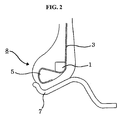
- Fig. 2 is a cross-sectional view of a tire according to one embodiment of the present invention, wherein a wedge-shaped rubber lump 5 having shore hardness of 95 ⁇ 100 is installed at the bottom of the bead in square shape in order to decrease movement of the bead 1 in the bead portion 8 mounted to the bead seat 7 of the rim, and a carcass ply 3 winds from the upper end to the lower end of the bead, and then from the upper surface to the side surface and to the bottom surface of said robber lump 5. It is much more effective for the carcass ply 3 to wind in above order than it winds in the order of bottom surface, the side surface and upper surface.
- the carcass ply can be manufactured easily in the following manner: the robber lump 5 winds at an arbitrary point of the molding drum, and one sheet of carcass ply 3 winds thereto, and the rubber lump 5 is turned down at both ends of the carcass ply 3 to wind the bead.
- the carcass ply 3 is pulled toward the side of the tire, and this force makes the carcass ply 3 push the bead 1 against the rubber lump 5. Then the rubber lump 5 is pushed to the rim and the bead 1 does not push rubber lump 5 any more. Therefore, the bead part 8 is not easily released from the rim because the bead part 8 is prevented from being released from the bead seat 7.
- Fig. 3 represents the pneumatic tire in which a flipper 4 is applied as a reinforcing structure.
- the flipper 4 overlaps the carcass ply 3 under the rubber lump 5, and extends along the side surface and upper surface of the rubber lump 5, and passes under the bead 1, and finally reaches above the bead 1 so that the bead 1 and the carcass ply 3 are not be deviated from the bead seat 7 area.
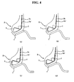
- FIG. 4 are cross-sectional views of the bead part of tire illustrating other embodiments of the present invention, wherein two sheets of carcass ply wind in various form in each bead part.
- the bead part is not easily released from the rim when the tire is deflated or under-inflated while driving, and the function of the tire is not affected. Therefore, the car accidents caused by released bead part can be prevented.
Landscapes
- Engineering & Computer Science (AREA)
- Mechanical Engineering (AREA)
- Tires In General (AREA)
Abstract
Description
- The present invention relates to a pneumatic tire with a rubber lump applied to the bead part, and more particularly, to a pneumatic tire wherein bead part is reinforced by using a rubber lump, and carcass ply or a reinforcing structure which encloses the rubber lump, to minimize the movement of the bead so that the bead portion is not easily released from the rim of the tire, especially the tire installed on the rim without flange, while driving under low air pressure of tire.
- In conventional pneumatic tires, a wedge is installed at the side of the bead so that the bead portion of the tire is not released from the rim when the tire is deflated or at low air pressure. As one example of prior art,
US Pat. No. 5,971,047 is illustrated inFig. 1 . As shown in the figure, the upper part ofcarcass ply 3 winds awedge 2 and is turned up, and thencircular bead 1 is installed wound on the carcass ply. This art requires many manufacturing steps and has many problems as described below. - First, the process of installing bead and wedge is very complicated, and there is a possibility that the bead is released from the rim due to the movement of the circular bead applied when the tire is deflated. Moreover, since the hardness of the
wedge 2 used is low, about 95 or lower, thewedge 2 can be deformed partially on the portion suppressed by thebead 1, and cannot perform desired role. - The object of the present invention is to improve the bead portion of the pneumatic tire installed on the rim, the toe of which is larger than the heel in diameter while not changing the function of the tire, and to provide a pneumatic tire which can prevent the bead portion from releasing from the rim when the tire is deflated so that car accidents can be prevented.
-
-
Fig. 1 is a sectional view of the bead portion of a conventional tire, -
Fig. 2 is a sectional view of the bead portion of a tire according to one embodiment of the present invention, -
Fig. 3 is a sectional view according to another embodiment of the present invention, which inserts reinforcing structure in the bead portion, and -
Fig. 4 a sectional view illustrating various embodiments of the present invention, in which two sheets of carcass ply are installed winding in various forms. -
1: bead, 2: wedge 3, 3a, 3a', 3b, 3b', 3c, 3c', 3d and 3d': carcass ply 4: flipper 5:rubber lump 6:flange 7:bead seat 8:bead portion - To achieve the object as stated above, a rubber lump is installed at the side surface of a bead, and a carcass ply winds the rubber lump in the same direction or in various shape, so that the rubber lump and the carcass ply wound thereto prevent the bead portion from being released from the bead seat of the rim when the tire is deflated.
- The constitution of the pneumatic tire having reinforced bead part of the present invention will be described in detail with reference to the accompanying drawings.
-
Fig. 2 is a cross-sectional view of a tire according to one embodiment of the present invention, wherein a wedge-shaped rubber lump 5 having shore hardness of 95 ∼ 100 is installed at the bottom of the bead in square shape in order to decrease movement of thebead 1 in thebead portion 8 mounted to thebead seat 7 of the rim, and a carcass ply 3 winds from the upper end to the lower end of the bead, and then from the upper surface to the side surface and to the bottom surface of saidrobber lump 5. It is much more effective for thecarcass ply 3 to wind in above order than it winds in the order of bottom surface, the side surface and upper surface. - Now the process of manufacturing the
bead part 8 in which thecarcass ply 3 winds therubber lump 5 will be described. - The carcass ply can be manufactured easily in the following manner: the robber lump 5 winds at an arbitrary point of the molding drum, and one sheet of
carcass ply 3 winds thereto, and therubber lump 5 is turned down at both ends of thecarcass ply 3 to wind the bead. - Accordingly, when the tire is deflated or under-inflated while driving, the
carcass ply 3 is pulled toward the side of the tire, and this force makes thecarcass ply 3 push thebead 1 against therubber lump 5. Then therubber lump 5 is pushed to the rim and thebead 1 does not pushrubber lump 5 any more. Therefore, thebead part 8 is not easily released from the rim because thebead part 8 is prevented from being released from thebead seat 7. -
Fig. 3 represents the pneumatic tire in which aflipper 4 is applied as a reinforcing structure. By using the reinforcing structure, the problem of prior art tire that the bead part of tire is moved to the wall area and released from thebead seat 7 when the tire is deflated or is under-inflated while driving can be overcome. As illustrated inFig. 3 , theflipper 4 overlaps thecarcass ply 3 under therubber lump 5, and extends along the side surface and upper surface of therubber lump 5, and passes under thebead 1, and finally reaches above thebead 1 so that thebead 1 and thecarcass ply 3 are not be deviated from thebead seat 7 area. - The figures (a), (b), (c) and (d) of
FIG. 4 are cross-sectional views of the bead part of tire illustrating other embodiments of the present invention, wherein two sheets of carcass ply wind in various form in each bead part. - While one sheet of carcass ply is applied in the bead part of
FIG. 2 andFIG. 3 respectively, two sheets of carcass ply are applied in the embodiments ofFig. 4 ; (a) twocarcass plies rubber lump 5, (b) two carcass plies 3b, 3b' wind to upper and lower part of therubber lump 5 and meet and overlap at the side of the rubber lump, (c) two carcass plies 3c, 3c' wind therubber lump 5 overlapping on the upper surface of therubber lump 5, one carcass ply winding to the middle of the side surface of therubber lump 5 and the other carcass ply overlapping said carcass ply and winding side surface of therubber lump 5 completely, (d) two carcass plies 3d, 3d' wind therubber lump 5, one carcass ply winding via lower surface of therubber lump 5 to the middle of the side surface of therubber lump 5 and the other carcass ply overlapping said carcass ply and winding therubber lump 5 completely. - By using the pneumatic tire with reinforced bead part of the present invention in a tire without flange, the bead part is not easily released from the rim when the tire is deflated or under-inflated while driving, and the function of the tire is not affected. Therefore, the car accidents caused by released bead part can be prevented.
Claims (4)
- A pneumatic tire with a reinforced bead part(8), said bead part including a bead(1) having an upper side and a lower side, a rubber lump(5) having an upper surface, a side surface and a lower surface, a carcass ply(3) and a flipper(4), wherein said tire is characterized in that the sectional shape of bead is substantially rectangular and the rubber lump(5) has a shore hardness between 95 and 100 and is installed below the lower side of the bead(1), the carcass ply(3) is wound around the lower surface of the rubber lump(5), and the flipper(4) overlaps the carcass ply(3) on the lower surface of the rubber lump(5), and is wound around the side surface and the upper surface of the rubber lump(5), the lower side and the axially inner side of the bead(1).
- A pneumatic tire with reinforced bead part(8) having a bead(1), said bead part including a bead having an upper side and a lower side, a rubber lump(5) having an upper surface, a side surface and a lower surface, wherein said tire is characterized in that the sectional shape of bead is substantially rectangular and the rubber lump(5) has a shore hardness between 95 and 100 and is installed below the lower side of the brad(1), and said tire comprises two sheets of carcass ply(3b, 3b'), one carcass ply being wound around an upper surface of the rubber lump(5), and the other carcass ply being wound around a lower surface of the rubber lump, and two carcass plies meeting at a side surface of the rubber lump(5) and overlapping, the overlapping plies partially wrapping around the bead(1).
- A pneumatic tire with a reinforced bead part(8) having a bead(1), said bead part including a bead having an upper side and a lower side, a rubber lump(5) having an upper surface, a side surface and a lower surface, wherein said tire is characterized in that the sectional shape of bead is substantially rectangular and the rubber lump has a shore hardness between 95 and 100 and is installed below the lower side of the bead, said tire comprises two sheets of carcass ply(3c, 3c'), one carcass ply being wound to the middle of a side surface of the rubber lump(5) and passing through the lower side and the axially inner side of the bead(1) and the other carcass ply being wound completely around the side surface of the rubber lump(5), and overlapping the one carcass ply on the side surface of the lump(5).
- A pneumatic tire with a reinforced bead part(8) having a bead(1), said bead part including a bead having an upper side and a lower side, a rubber lump(5) having an upper surface, a side surface and a lower surface, wherein said tire is characterized in that the sectional shape of bead is substantially rectangular and the rubber lump has a shore hardness between 95 and 100 and is installed below the lower side of the bead(1), said tire comprises two sheets of carcass ply(3d, 3d'), one carcass ply being wound around the middle of a side surface of the rubber lump(5) and a lower surface of the rubber lump(5), and the other carcass ply being overlapping the one carcass ply and being wound completely around the rubber lump(5).
Applications Claiming Priority (3)
| Application Number | Priority Date | Filing Date | Title |
|---|---|---|---|
| KR2001014259 | 2001-03-20 | ||
| KR10-2001-0014259A KR100393476B1 (en) | 2001-03-20 | 2001-03-20 | Pneumatic Tire with Reinforced Bead Part |
| PCT/KR2001/001483 WO2002076767A1 (en) | 2001-03-20 | 2001-08-31 | Pneumatic tire with reinforced bead part |
Publications (3)
| Publication Number | Publication Date |
|---|---|
| EP1377464A1 EP1377464A1 (en) | 2004-01-07 |
| EP1377464A4 EP1377464A4 (en) | 2006-04-05 |
| EP1377464B1 true EP1377464B1 (en) | 2009-05-27 |
Family
ID=19707130
Family Applications (1)
| Application Number | Title | Priority Date | Filing Date |
|---|---|---|---|
| EP01963601A Expired - Lifetime EP1377464B1 (en) | 2001-03-20 | 2001-08-31 | Pneumatic tire with reinforced bead part |
Country Status (7)
| Country | Link |
|---|---|
| US (1) | US7225846B2 (en) |
| EP (1) | EP1377464B1 (en) |
| JP (1) | JP2004523419A (en) |
| KR (1) | KR100393476B1 (en) |
| CA (1) | CA2441527A1 (en) |
| DE (1) | DE60138838D1 (en) |
| WO (1) | WO2002076767A1 (en) |
Families Citing this family (4)
| Publication number | Priority date | Publication date | Assignee | Title |
|---|---|---|---|---|
| US6779574B2 (en) * | 2001-11-27 | 2004-08-24 | Michelin Recherche Et Technique S.A. | Tire with multiple carcass reinforcement plies having beads of specified structure |
| WO2008063178A1 (en) * | 2006-11-22 | 2008-05-29 | Michelin Recherche Et Technique S.A. | Tire with improved bead portion |
| KR100985150B1 (en) * | 2008-07-10 | 2010-10-08 | 강준길 | Silencer for internal combustion engine and engine for internal combustion engine having same |
| US8627866B2 (en) * | 2009-01-09 | 2014-01-14 | Bridgestone Americas Tire Operations, Llc | Tire and wheel rim assembly |
Family Cites Families (10)
| Publication number | Priority date | Publication date | Assignee | Title |
|---|---|---|---|---|
| EP0077161A3 (en) * | 1981-10-09 | 1984-03-21 | Dunlop Limited | A tyre |
| JP2644518B2 (en) * | 1988-02-23 | 1997-08-25 | 株式会社ブリヂストン | Pneumatic radial tire for aircraft |
| JPH06227216A (en) * | 1992-12-07 | 1994-08-16 | Bridgestone Corp | Pneumatic radial tire |
| JP3355222B2 (en) * | 1993-07-02 | 2002-12-09 | 株式会社ブリヂストン | Pneumatic radial tires for passenger cars |
| JP2916082B2 (en) * | 1993-08-10 | 1999-07-05 | 住友ゴム工業株式会社 | Pneumatic radial tire |
| FR2716645B1 (en) * | 1994-02-28 | 1996-04-19 | Michelin & Cie | Tire with beads of improved structure and assembly of such a tire with a suitable rim. |
| JP2962658B2 (en) * | 1994-08-22 | 1999-10-12 | 住友ゴム工業株式会社 | Pneumatic tubeless tire |
| FR2773518A1 (en) * | 1998-01-12 | 1999-07-16 | Michelin & Cie | TIRE SADDLE WITH CIRCUMFERENTIAL REINFORCEMENT ELEMENTS |
| JP4244246B2 (en) * | 1998-10-15 | 2009-03-25 | 株式会社ブリヂストン | Pneumatic tire |
| ATE317772T1 (en) * | 2001-07-31 | 2006-03-15 | Michelin Soc Tech | Pneumatic tire bead with protective rib |
-
2001
- 2001-03-20 KR KR10-2001-0014259A patent/KR100393476B1/en not_active Expired - Fee Related
- 2001-08-31 US US10/472,603 patent/US7225846B2/en not_active Expired - Fee Related
- 2001-08-31 CA CA002441527A patent/CA2441527A1/en not_active Abandoned
- 2001-08-31 EP EP01963601A patent/EP1377464B1/en not_active Expired - Lifetime
- 2001-08-31 WO PCT/KR2001/001483 patent/WO2002076767A1/en not_active Ceased
- 2001-08-31 DE DE60138838T patent/DE60138838D1/de not_active Expired - Lifetime
- 2001-08-31 JP JP2002575252A patent/JP2004523419A/en active Pending
Also Published As
| Publication number | Publication date |
|---|---|
| US7225846B2 (en) | 2007-06-05 |
| JP2004523419A (en) | 2004-08-05 |
| CA2441527A1 (en) | 2002-10-03 |
| EP1377464A1 (en) | 2004-01-07 |
| KR100393476B1 (en) | 2003-08-02 |
| WO2002076767A1 (en) | 2002-10-03 |
| EP1377464A4 (en) | 2006-04-05 |
| DE60138838D1 (en) | 2009-07-09 |
| US20040134583A1 (en) | 2004-07-15 |
| KR20020074318A (en) | 2002-09-30 |
Similar Documents
| Publication | Publication Date | Title |
|---|---|---|
| US6913052B2 (en) | Tire with composite ply structure and method of manufacture | |
| EP2052879A1 (en) | Multiple ply modular tire carcass construction | |
| JPH04218413A (en) | Pneumatic tire | |
| EP1094956B1 (en) | Runflat tire having a fabric underlay for improving tread circumferential and meridional rigidity and method of constructing | |
| US7225846B2 (en) | Pneumatic tire with reinforced bead part | |
| EP3725565B1 (en) | Pneumatic tire with bead filler applied with multiple rubber layer | |
| US6378585B1 (en) | Heavy duty pneumatic tire and method of manufacturing the same | |
| EP1433590B1 (en) | Tire with composite ply structure and method of manufacture | |
| JP4507920B2 (en) | Method for manufacturing run-flat tires | |
| AU2007203377B2 (en) | Pneumatic tire with reinforced bead part | |
| JPH11309789A (en) | Production of pneumatic tire | |
| JP4399849B2 (en) | Run-flat tire and method for producing the run-flat tire | |
| EP2665598B1 (en) | Tyre and tyre building method | |
| AU2001284533A1 (en) | Pneumatic tire with reinforced bead part | |
| JP4507921B2 (en) | Run-flat tire and manufacturing method thereof | |
| JP4606184B2 (en) | Pneumatic tire | |
| EP0638410B1 (en) | Process for the manufacture of pneumatic radial tires | |
| EP1377465B1 (en) | Pneumatic tire with reinforced bead part | |
| JP4518605B2 (en) | Pneumatic tire | |
| EP1878564B1 (en) | Method of manufacturing run-flat tire | |
| KR200262877Y1 (en) | Pneumatictire for heavy vehiche | |
| JP2002528336A (en) | 2-ply run flat tire with reinforced tread | |
| KR200245689Y1 (en) | Aircraft tires with reinforced side parts | |
| JPH03213409A (en) | Heavy duty pneumatic radial tire | |
| KR0139280B1 (en) | Tire molding method and the manufactured tire |
Legal Events
| Date | Code | Title | Description |
|---|---|---|---|
| PUAI | Public reference made under article 153(3) epc to a published international application that has entered the european phase |
Free format text: ORIGINAL CODE: 0009012 |
|
| 17P | Request for examination filed |
Effective date: 20031001 |
|
| AK | Designated contracting states |
Kind code of ref document: A1 Designated state(s): AT BE CH CY DE DK ES FI FR GB GR IE IT LI LU MC NL PT SE TR |
|
| AX | Request for extension of the european patent |
Extension state: AL LT LV MK RO SI |
|
| RAP1 | Party data changed (applicant data changed or rights of an application transferred) |
Owner name: KUMHO TIRE CO., INC. |
|
| A4 | Supplementary search report drawn up and despatched |
Effective date: 20060217 |
|
| RIC1 | Information provided on ipc code assigned before grant |
Ipc: B60C 15/00 20060101ALI20060213BHEP Ipc: B60C 9/02 20060101AFI20021004BHEP |
|
| GRAP | Despatch of communication of intention to grant a patent |
Free format text: ORIGINAL CODE: EPIDOSNIGR1 |
|
| RBV | Designated contracting states (corrected) |
Designated state(s): DE FR GB IT |
|
| GRAS | Grant fee paid |
Free format text: ORIGINAL CODE: EPIDOSNIGR3 |
|
| GRAA | (expected) grant |
Free format text: ORIGINAL CODE: 0009210 |
|
| AK | Designated contracting states |
Kind code of ref document: B1 Designated state(s): DE FR GB IT |
|
| REG | Reference to a national code |
Ref country code: GB Ref legal event code: FG4D |
|
| REF | Corresponds to: |
Ref document number: 60138838 Country of ref document: DE Date of ref document: 20090709 Kind code of ref document: P |
|
| PGFP | Annual fee paid to national office [announced via postgrant information from national office to epo] |
Ref country code: GB Payment date: 20090922 Year of fee payment: 9 Ref country code: DE Payment date: 20090911 Year of fee payment: 9 |
|
| PLBE | No opposition filed within time limit |
Free format text: ORIGINAL CODE: 0009261 |
|
| STAA | Information on the status of an ep patent application or granted ep patent |
Free format text: STATUS: NO OPPOSITION FILED WITHIN TIME LIMIT |
|
| PGFP | Annual fee paid to national office [announced via postgrant information from national office to epo] |
Ref country code: IT Payment date: 20090831 Year of fee payment: 9 |
|
| 26N | No opposition filed |
Effective date: 20100302 |
|
| GBPC | Gb: european patent ceased through non-payment of renewal fee |
Effective date: 20100831 |
|
| REG | Reference to a national code |
Ref country code: FR Ref legal event code: ST Effective date: 20110502 |
|
| PG25 | Lapsed in a contracting state [announced via postgrant information from national office to epo] |
Ref country code: IT Free format text: LAPSE BECAUSE OF NON-PAYMENT OF DUE FEES Effective date: 20100831 |
|
| REG | Reference to a national code |
Ref country code: DE Ref legal event code: R119 Ref document number: 60138838 Country of ref document: DE Effective date: 20110301 |
|
| PG25 | Lapsed in a contracting state [announced via postgrant information from national office to epo] |
Ref country code: FR Free format text: LAPSE BECAUSE OF NON-PAYMENT OF DUE FEES Effective date: 20100831 Ref country code: DE Free format text: LAPSE BECAUSE OF NON-PAYMENT OF DUE FEES Effective date: 20110301 |
|
| PG25 | Lapsed in a contracting state [announced via postgrant information from national office to epo] |
Ref country code: GB Free format text: LAPSE BECAUSE OF NON-PAYMENT OF DUE FEES Effective date: 20100831 |
|
| PGFP | Annual fee paid to national office [announced via postgrant information from national office to epo] |
Ref country code: FR Payment date: 20090915 Year of fee payment: 9 |