EP1377375B1 - Bayerite alumina coated zeolite and cracking catalysts containing same - Google Patents
Bayerite alumina coated zeolite and cracking catalysts containing same Download PDFInfo
- Publication number
- EP1377375B1 EP1377375B1 EP02728633A EP02728633A EP1377375B1 EP 1377375 B1 EP1377375 B1 EP 1377375B1 EP 02728633 A EP02728633 A EP 02728633A EP 02728633 A EP02728633 A EP 02728633A EP 1377375 B1 EP1377375 B1 EP 1377375B1
- Authority
- EP
- European Patent Office
- Prior art keywords
- zeolite
- particles
- cracking
- product
- catalyst
- Prior art date
- Legal status (The legal status is an assumption and is not a legal conclusion. Google has not performed a legal analysis and makes no representation as to the accuracy of the status listed.)
- Expired - Lifetime
Links
- HNPSIPDUKPIQMN-UHFFFAOYSA-N dioxosilane;oxo(oxoalumanyloxy)alumane Chemical compound O=[Si]=O.O=[Al]O[Al]=O HNPSIPDUKPIQMN-UHFFFAOYSA-N 0.000 title claims abstract description 99
- 239000003054 catalyst Substances 0.000 title claims abstract description 94
- 239000010457 zeolite Substances 0.000 title claims abstract description 79
- 229910021536 Zeolite Inorganic materials 0.000 title claims abstract description 66
- PNEYBMLMFCGWSK-UHFFFAOYSA-N aluminium oxide Inorganic materials [O-2].[O-2].[O-2].[Al+3].[Al+3] PNEYBMLMFCGWSK-UHFFFAOYSA-N 0.000 title claims abstract description 52
- 229910001680 bayerite Inorganic materials 0.000 title claims abstract description 41
- 238000005336 cracking Methods 0.000 title claims description 66
- 238000004231 fluid catalytic cracking Methods 0.000 claims abstract description 31
- 238000000576 coating method Methods 0.000 claims abstract description 15
- 239000011248 coating agent Substances 0.000 claims abstract description 14
- 239000003208 petroleum Substances 0.000 claims abstract description 7
- 238000000034 method Methods 0.000 claims description 47
- 239000002245 particle Substances 0.000 claims description 45
- 230000008569 process Effects 0.000 claims description 33
- 239000002002 slurry Substances 0.000 claims description 33
- 229930195733 hydrocarbon Natural products 0.000 claims description 19
- 150000002430 hydrocarbons Chemical class 0.000 claims description 19
- 239000000243 solution Substances 0.000 claims description 19
- 239000000203 mixture Substances 0.000 claims description 16
- 239000004215 Carbon black (E152) Substances 0.000 claims description 15
- 229910052782 aluminium Inorganic materials 0.000 claims description 14
- ANBBXQWFNXMHLD-UHFFFAOYSA-N aluminum;sodium;oxygen(2-) Chemical group [O-2].[O-2].[Na+].[Al+3] ANBBXQWFNXMHLD-UHFFFAOYSA-N 0.000 claims description 14
- 229910001388 sodium aluminate Inorganic materials 0.000 claims description 14
- XLYOFNOQVPJJNP-UHFFFAOYSA-N water Substances O XLYOFNOQVPJJNP-UHFFFAOYSA-N 0.000 claims description 14
- 239000002585 base Substances 0.000 claims description 13
- -1 aluminum ion Chemical class 0.000 claims description 10
- 238000004523 catalytic cracking Methods 0.000 claims description 8
- 239000000463 material Substances 0.000 claims description 7
- 230000008929 regeneration Effects 0.000 claims description 6
- 238000011069 regeneration method Methods 0.000 claims description 6
- 238000002156 mixing Methods 0.000 claims description 5
- 150000008044 alkali metal hydroxides Chemical group 0.000 claims description 4
- VHUUQVKOLVNVRT-UHFFFAOYSA-N Ammonium hydroxide Chemical compound [NH4+].[OH-] VHUUQVKOLVNVRT-UHFFFAOYSA-N 0.000 claims description 3
- DGAQECJNVWCQMB-PUAWFVPOSA-M Ilexoside XXIX Chemical compound C[C@@H]1CC[C@@]2(CC[C@@]3(C(=CC[C@H]4[C@]3(CC[C@@H]5[C@@]4(CC[C@@H](C5(C)C)OS(=O)(=O)[O-])C)C)[C@@H]2[C@]1(C)O)C)C(=O)O[C@H]6[C@@H]([C@H]([C@@H]([C@H](O6)CO)O)O)O.[Na+] DGAQECJNVWCQMB-PUAWFVPOSA-M 0.000 claims description 3
- 229910052783 alkali metal Inorganic materials 0.000 claims description 3
- 239000000908 ammonium hydroxide Substances 0.000 claims description 2
- 239000011734 sodium Substances 0.000 claims description 2
- 229910052708 sodium Inorganic materials 0.000 claims description 2
- 239000007864 aqueous solution Substances 0.000 claims 1
- 239000011159 matrix material Substances 0.000 description 15
- 239000000047 product Substances 0.000 description 13
- DIZPMCHEQGEION-UHFFFAOYSA-H aluminium sulfate (anhydrous) Chemical compound [Al+3].[Al+3].[O-]S([O-])(=O)=O.[O-]S([O-])(=O)=O.[O-]S([O-])(=O)=O DIZPMCHEQGEION-UHFFFAOYSA-H 0.000 description 12
- 150000003839 salts Chemical class 0.000 description 10
- 239000000571 coke Substances 0.000 description 9
- 239000006185 dispersion Substances 0.000 description 9
- XAGFODPZIPBFFR-UHFFFAOYSA-N aluminium Chemical compound [Al] XAGFODPZIPBFFR-UHFFFAOYSA-N 0.000 description 8
- 229910052593 corundum Inorganic materials 0.000 description 8
- 238000001556 precipitation Methods 0.000 description 8
- 229910001845 yogo sapphire Inorganic materials 0.000 description 8
- 239000011230 binding agent Substances 0.000 description 7
- 239000004927 clay Substances 0.000 description 7
- 229910052739 hydrogen Inorganic materials 0.000 description 7
- 239000001257 hydrogen Substances 0.000 description 7
- UFHFLCQGNIYNRP-UHFFFAOYSA-N Hydrogen Chemical compound [H][H] UFHFLCQGNIYNRP-UHFFFAOYSA-N 0.000 description 6
- HEMHJVSKTPXQMS-UHFFFAOYSA-M Sodium hydroxide Chemical compound [OH-].[Na+] HEMHJVSKTPXQMS-UHFFFAOYSA-M 0.000 description 6
- 230000015572 biosynthetic process Effects 0.000 description 6
- 230000000694 effects Effects 0.000 description 6
- 239000002253 acid Substances 0.000 description 5
- 238000006243 chemical reaction Methods 0.000 description 5
- 238000005253 cladding Methods 0.000 description 5
- 239000003921 oil Substances 0.000 description 5
- KKCBUQHMOMHUOY-UHFFFAOYSA-N Na2O Inorganic materials [O-2].[Na+].[Na+] KKCBUQHMOMHUOY-UHFFFAOYSA-N 0.000 description 4
- PXHVJJICTQNCMI-UHFFFAOYSA-N Nickel Chemical compound [Ni] PXHVJJICTQNCMI-UHFFFAOYSA-N 0.000 description 4
- VYPSYNLAJGMNEJ-UHFFFAOYSA-N Silicium dioxide Chemical compound O=[Si]=O VYPSYNLAJGMNEJ-UHFFFAOYSA-N 0.000 description 4
- 229940037003 alum Drugs 0.000 description 4
- VXAUWWUXCIMFIM-UHFFFAOYSA-M aluminum;oxygen(2-);hydroxide Chemical compound [OH-].[O-2].[Al+3] VXAUWWUXCIMFIM-UHFFFAOYSA-M 0.000 description 4
- 238000001035 drying Methods 0.000 description 4
- 239000007789 gas Substances 0.000 description 4
- 229910052751 metal Inorganic materials 0.000 description 4
- 239000002184 metal Substances 0.000 description 4
- 238000012545 processing Methods 0.000 description 4
- 238000004627 transmission electron microscopy Methods 0.000 description 4
- 238000005406 washing Methods 0.000 description 4
- 230000002378 acidificating effect Effects 0.000 description 3
- 229910001593 boehmite Inorganic materials 0.000 description 3
- 230000008021 deposition Effects 0.000 description 3
- 239000012013 faujasite Substances 0.000 description 3
- 239000012065 filter cake Substances 0.000 description 3
- FAHBNUUHRFUEAI-UHFFFAOYSA-M hydroxidooxidoaluminium Chemical compound O[Al]=O FAHBNUUHRFUEAI-UHFFFAOYSA-M 0.000 description 3
- 238000010348 incorporation Methods 0.000 description 3
- NLYAJNPCOHFWQQ-UHFFFAOYSA-N kaolin Chemical compound O.O.O=[Al]O[Si](=O)O[Si](=O)O[Al]=O NLYAJNPCOHFWQQ-UHFFFAOYSA-N 0.000 description 3
- QGZKDVFQNNGYKY-UHFFFAOYSA-N Ammonia Chemical compound N QGZKDVFQNNGYKY-UHFFFAOYSA-N 0.000 description 2
- QAOWNCQODCNURD-UHFFFAOYSA-N Sulfuric acid Chemical compound OS(O)(=O)=O QAOWNCQODCNURD-UHFFFAOYSA-N 0.000 description 2
- 238000007792 addition Methods 0.000 description 2
- 239000000654 additive Substances 0.000 description 2
- 230000002411 adverse Effects 0.000 description 2
- 235000011114 ammonium hydroxide Nutrition 0.000 description 2
- 239000003637 basic solution Substances 0.000 description 2
- 238000001354 calcination Methods 0.000 description 2
- 230000003197 catalytic effect Effects 0.000 description 2
- 238000007796 conventional method Methods 0.000 description 2
- 238000001914 filtration Methods 0.000 description 2
- 239000007788 liquid Substances 0.000 description 2
- 238000004519 manufacturing process Methods 0.000 description 2
- 150000002739 metals Chemical class 0.000 description 2
- 239000000843 powder Substances 0.000 description 2
- 238000002360 preparation method Methods 0.000 description 2
- QQONPFPTGQHPMA-UHFFFAOYSA-N propylene Natural products CC=C QQONPFPTGQHPMA-UHFFFAOYSA-N 0.000 description 2
- RMAQACBXLXPBSY-UHFFFAOYSA-N silicic acid Chemical compound O[Si](O)(O)O RMAQACBXLXPBSY-UHFFFAOYSA-N 0.000 description 2
- 239000000377 silicon dioxide Substances 0.000 description 2
- 238000012360 testing method Methods 0.000 description 2
- 239000005995 Aluminium silicate Substances 0.000 description 1
- 239000007848 Bronsted acid Substances 0.000 description 1
- VQTUBCCKSQIDNK-UHFFFAOYSA-N Isobutene Chemical group CC(C)=C VQTUBCCKSQIDNK-UHFFFAOYSA-N 0.000 description 1
- 239000002841 Lewis acid Substances 0.000 description 1
- MXRIRQGCELJRSN-UHFFFAOYSA-N O.O.O.[Al] Chemical compound O.O.O.[Al] MXRIRQGCELJRSN-UHFFFAOYSA-N 0.000 description 1
- 239000004115 Sodium Silicate Substances 0.000 description 1
- 238000002441 X-ray diffraction Methods 0.000 description 1
- 150000008043 acidic salts Chemical class 0.000 description 1
- 239000003929 acidic solution Substances 0.000 description 1
- 230000000996 additive effect Effects 0.000 description 1
- 150000001336 alkenes Chemical class 0.000 description 1
- AZDRQVAHHNSJOQ-UHFFFAOYSA-N alumane Chemical class [AlH3] AZDRQVAHHNSJOQ-UHFFFAOYSA-N 0.000 description 1
- 150000004645 aluminates Chemical class 0.000 description 1
- 229910000323 aluminium silicate Inorganic materials 0.000 description 1
- 235000012211 aluminium silicate Nutrition 0.000 description 1
- 229910000329 aluminium sulfate Inorganic materials 0.000 description 1
- 229910021529 ammonia Inorganic materials 0.000 description 1
- 238000004458 analytical method Methods 0.000 description 1
- 230000003190 augmentative effect Effects 0.000 description 1
- 238000010923 batch production Methods 0.000 description 1
- 238000009835 boiling Methods 0.000 description 1
- 229910052799 carbon Inorganic materials 0.000 description 1
- 125000004432 carbon atom Chemical group C* 0.000 description 1
- 150000001768 cations Chemical class 0.000 description 1
- 238000002485 combustion reaction Methods 0.000 description 1
- 150000001875 compounds Chemical class 0.000 description 1
- 239000000470 constituent Substances 0.000 description 1
- 238000010924 continuous production Methods 0.000 description 1
- 238000002425 crystallisation Methods 0.000 description 1
- 230000008025 crystallization Effects 0.000 description 1
- 230000009849 deactivation Effects 0.000 description 1
- 239000012530 fluid Substances 0.000 description 1
- 150000002431 hydrogen Chemical class 0.000 description 1
- XLYOFNOQVPJJNP-UHFFFAOYSA-M hydroxide Chemical compound [OH-] XLYOFNOQVPJJNP-UHFFFAOYSA-M 0.000 description 1
- 230000006872 improvement Effects 0.000 description 1
- 229910052500 inorganic mineral Inorganic materials 0.000 description 1
- 238000005342 ion exchange Methods 0.000 description 1
- 150000007517 lewis acids Chemical class 0.000 description 1
- VTHJTEIRLNZDEV-UHFFFAOYSA-L magnesium dihydroxide Chemical compound [OH-].[OH-].[Mg+2] VTHJTEIRLNZDEV-UHFFFAOYSA-L 0.000 description 1
- 239000000347 magnesium hydroxide Substances 0.000 description 1
- 229910001862 magnesium hydroxide Inorganic materials 0.000 description 1
- 230000014759 maintenance of location Effects 0.000 description 1
- 238000005259 measurement Methods 0.000 description 1
- 229910044991 metal oxide Inorganic materials 0.000 description 1
- 239000011707 mineral Substances 0.000 description 1
- 239000002808 molecular sieve Substances 0.000 description 1
- 239000012452 mother liquor Substances 0.000 description 1
- 229910052759 nickel Inorganic materials 0.000 description 1
- 230000001590 oxidative effect Effects 0.000 description 1
- 238000002161 passivation Methods 0.000 description 1
- 238000005504 petroleum refining Methods 0.000 description 1
- 239000012071 phase Substances 0.000 description 1
- 239000011148 porous material Substances 0.000 description 1
- 230000002028 premature Effects 0.000 description 1
- 238000004886 process control Methods 0.000 description 1
- 238000005086 pumping Methods 0.000 description 1
- 229910052761 rare earth metal Inorganic materials 0.000 description 1
- 229910001404 rare earth metal oxide Inorganic materials 0.000 description 1
- 230000009467 reduction Effects 0.000 description 1
- 229930195734 saturated hydrocarbon Natural products 0.000 description 1
- 229910052710 silicon Inorganic materials 0.000 description 1
- 239000010703 silicon Substances 0.000 description 1
- 238000005549 size reduction Methods 0.000 description 1
- URGAHOPLAPQHLN-UHFFFAOYSA-N sodium aluminosilicate Chemical compound [Na+].[Al+3].[O-][Si]([O-])=O.[O-][Si]([O-])=O URGAHOPLAPQHLN-UHFFFAOYSA-N 0.000 description 1
- NTHWMYGWWRZVTN-UHFFFAOYSA-N sodium silicate Chemical compound [Na+].[Na+].[O-][Si]([O-])=O NTHWMYGWWRZVTN-UHFFFAOYSA-N 0.000 description 1
- 229910052911 sodium silicate Inorganic materials 0.000 description 1
- 238000001228 spectrum Methods 0.000 description 1
- 239000012798 spherical particle Substances 0.000 description 1
- 238000001694 spray drying Methods 0.000 description 1
- 238000010561 standard procedure Methods 0.000 description 1
- 239000000126 substance Substances 0.000 description 1
- 239000012808 vapor phase Substances 0.000 description 1
Images
Classifications
-
- B—PERFORMING OPERATIONS; TRANSPORTING
- B01—PHYSICAL OR CHEMICAL PROCESSES OR APPARATUS IN GENERAL
- B01J—CHEMICAL OR PHYSICAL PROCESSES, e.g. CATALYSIS OR COLLOID CHEMISTRY; THEIR RELEVANT APPARATUS
- B01J29/00—Catalysts comprising molecular sieves
- B01J29/04—Catalysts comprising molecular sieves having base-exchange properties, e.g. crystalline zeolites
- B01J29/06—Crystalline aluminosilicate zeolites; Isomorphous compounds thereof
- B01J29/08—Crystalline aluminosilicate zeolites; Isomorphous compounds thereof of the faujasite type, e.g. type X or Y
- B01J29/084—Y-type faujasite
-
- B—PERFORMING OPERATIONS; TRANSPORTING
- B01—PHYSICAL OR CHEMICAL PROCESSES OR APPARATUS IN GENERAL
- B01J—CHEMICAL OR PHYSICAL PROCESSES, e.g. CATALYSIS OR COLLOID CHEMISTRY; THEIR RELEVANT APPARATUS
- B01J37/00—Processes, in general, for preparing catalysts; Processes, in general, for activation of catalysts
- B01J37/02—Impregnation, coating or precipitation
- B01J37/0215—Coating
-
- B—PERFORMING OPERATIONS; TRANSPORTING
- B01—PHYSICAL OR CHEMICAL PROCESSES OR APPARATUS IN GENERAL
- B01J—CHEMICAL OR PHYSICAL PROCESSES, e.g. CATALYSIS OR COLLOID CHEMISTRY; THEIR RELEVANT APPARATUS
- B01J37/00—Processes, in general, for preparing catalysts; Processes, in general, for activation of catalysts
- B01J37/02—Impregnation, coating or precipitation
- B01J37/03—Precipitation; Co-precipitation
- B01J37/031—Precipitation
Definitions
- the present invention is directed to fluid catalytic cracking catalysts comprising zeolite particles which are coated with bayerite alumina, and to FCC processes which utilize the subject catalyst.
- Catalytic cracking is a petroleum refining process which is applied commercially on a very large scale.
- a majority of the refinery gasoline blending pool in the United States is produced using the fluid catalytic cracking (FCC) process.
- FCC fluid catalytic cracking
- heavy hydrocarbon fractions are converted into lighter products by reactions taking place at elevated temperature in the presence of a catalyst, with the majority of the conversion or cracking occurring in the vapor phase.
- the feedstock is thereby converted into gasoline, distillate and other liquid cracking products as well as lighter gaseous cracking products of four or less carbon atoms per molecule.
- the gas partly consists of olefins and partly of saturated hydrocarbons.
- Cracking catalysts used in FCC processes are fine porous powders composed of oxides of silica and aluminum. Other elements may be present in very small amounts. Either Bronsted or Lewis acid sites associated with the aluminum are believed to initiate and accelerate carbocation reactions that cause molecular size reduction of the petroleum oils under the FCC reactor conditions. When aerated with gas, the powder attains a fluid-like state that permits its circulation through the various FCC process zones.
- the three characteristic process zones of the FCC process are composed of: a cracking step in which the hydrocarbons are converted into lighter products, a stripping step to remove hydrocarbons adsorbed on the catalyst and a regeneration step to burn off coke from the catalyst. The regenerated catalyst is then reused in the cracking step.
- FCC catalysts have been formed from mixtures of zeolites with an active matrix material, such as various forms of alumina, or have been coated.
- an active matrix material such as various forms of alumina
- JP laid-open application SHO 58-112,051 discloses the formation of a zeolite, which has been coated with a metallic oxide prior to incorporation into the catalyst composition.
- the zeolite is dispersed in an aqueous acidic solution of the metal salt and then treated with ammonia water to raise the pH to about 9 causing the metal to deposit as the hydroxide on the surface of the zeolite.
- the resultant coating is a relatively amorphous alumina.
- FCC catalysts have also been formed from zeolites which are augmented by active matrix materials of aluminas.
- U.S. Patent 5,168,086 discloses the mixing of bayeriteleta alumina particles into the cracking catalyst matrix to improve its tolerance to nickel-containing feedstocks.
- the zeolite is mixed with the alumina along with other conventional matrix components and then calcined to form the catalyst particles.
- Cracking catalysts must be able to crack the range of constituents in a feedstock to achieve the desired output.
- the cracking catalyst itself may contain various components ranging from zeolites, active matrix materials (e.g., alumina, relatively inactive matrix materials (e.g., clay) to binders (e.g., sols).
- Active matrix materials e.g., alumina
- relatively inactive matrix materials e.g., clay
- binders e.g., sols.
- Cracking catalysts, especially for FCC processes are necessarily constrained as to their particle size by virtue of the fact a the catalyst particles must be adequately fluidizable in the process.
- An additional constraint is that the catalyst must be attrition resistant.
- the requirement for attribution resistance generally means that a significant amount of clay and binder must be present in the catalyst particle.
- there is only limited room in the catalyst particle for those components that are responsible for the majority of the cracking function i.e., zeolite/active matrix).
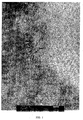
- Figure 1 is a picture of the product of Example 1 obtained by transmission electron microscopy (TEM) showing a portion of a zeolite particle (left dark portion of picture) with bayerite alumina cladding thereon.
- the scale of the picture is 1 cm represents 50 nm.
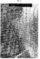
- Figure 2 is a second picture of the product of Example 1 obtained by TEM technique showing a portion of a zeolite particle (left dark portion of picture) with bayerite alumina cladding thereon.
- the scale of the picture is 1 cm represents 20 mn.
- the present invention is directed to a method of forming bayerite alumina coated zeolite particles as defined in claim 1.
- the present invention is also directed to a bayerite alumina-coated zeolite particulate product obtainable by this process, as well as hydrocarbon cracking catalysts containing said bayerite alumina-clad zeolite and FCC processes using said catalysts.
- the present invention is further directed to FCC catalyst compositions comprising the subject bayerite alumina-clad zeolite dispersed in a silica or alumina type matrix. More specifically, the present FCC catalyst composition comprises fine particulates of bayerite alumina-clad zeolite, optionally additional active-matrix materials, along with conventional clays and binder.
- the present invention is directed to FCC processes that utilize the present bayerite alumina-clad zeolite containing catalyst composition.
- the present FCC process is an improved hydrocarbon cracking process which minimizes coke formation and/or maximizes cracking of heavy "bottom" feedstock to produce higher yields of desired products.
- the present invention is directed to specific bayerite alumina-clad zeolite particles, the process of forming said particles, the formation of hydrocarbon cracking catalysts using said bayerite alumina-clad zeolite as a major component, and catalytic hydrocarbon cracking processes using the present cracking catalyst.
- aluminas of various morphology may be added to catalytic cracking catalysts to improve the stability of the catalyst and to aid in coke/dry gas selectivity.
- Boehmite and pseudo-boehmite have been incorporated into the catalysts either as separate particles or as a coating on the zeolite molecular sieve of the catalyst.
- U.S. Patents 4,010,116 and 4,332,699 disclose pseudo-boehmite containing catalysts and Canadian Patent 1,117,511 describes an FCC catalyst which contains free boehmite in the catalyst composition.
- Fluid cracking catalysts are well known in the petroleum industry for forming desired gasoline and light oil materials, as well as C 1 -C 4 hydrocarbon products, from petroleum feedstocks.
- the catalysts normally consist of a range of extremely small spherical particles. Commercial grades normally have average particle sizes ranging from about 25 to 100 microns, preferably from about 50 to about 75 microns.
- the cracking catalysts are comprised of a number of components, each of which is designed to enhance the overall performance of the catalyst. Some of the components influence activity and selectivity while others affect the integrity and retention properties of the catalyst particles.
- FCC catalysts are generally composed of zeolite, active matrix, clay and binder with all of the components incorporated into a single particle or are compiled of blends of individual particles having different functions.
- zeolite The primary source of activity of cracking catalyst is zeolite.
- zeolite indicates a natural or synthetic faujasite. Faujasite is a crystalline three-dimensional aluminosilicate of the zeolite mineral group which has ion-exchange capacity, These materials have pore openings of about 7 to 9 ⁇ . Faujasite is known to occur naturally but, due to its scarcity it is formed synthetically in the sodium form by crystallization of sodium aluminate and sodium silicate (Standard Y type zeolite).
- any zeolite suitable for hydrocarbon catalytic cracking can be used in the present invention
- the preferred types of zeolites found useful herein are X and Y zeolite with the Y types being more preferred and the Standard Y type zeolite being most preferred.
- the Standard Y is formed in the manner described above and can be exchanged to remove a portion of the sodium by hydrogen (HY) and/or by exchange with rare earth metal ions (REY).
- REY rare earth metal ions
- an ultrastable Y zeolite USY type
- Each of the various types of zeolites can be used in forming the bayerite alumina-clad zeolite of the present invention.
- zeolite is clad with bayerite alumina by initially mixing an aqueous dispersion of zeolite with an aluminum ion source such as an acidic salt of aluminum as, for example, aluminum sulfate (alum) under acidic conditions.
- an aluminum ion source such as an acidic salt of aluminum as, for example, aluminum sulfate (alum) under acidic conditions.
- the resultant acidic dispersion is then contacted with a solution of a strong base in sufficient amount and having a sufficiently high pH to immediately transform the pH of the dispersion to a value of from 10 to 11.5 and preferably from at least 10.5 to 11.5.
- the equilibrium pH of the resultant dispersion should be between 10 and 11.5, preferably between 10.0 and 10.5.
- the equilibrium pH of the mixture of zeolite dispersion and base solution should be between 10 to 11.5, preferably between 10 to 10.5. This can be maintained by adjusting the rate of introduction of the acidic zeolite dispersion and basic solution.
- the base can be any strong base which does not have an adverse effect on the zeolite structure.
- Preferred bases are alkali metal hydroxides, such as sodium hydroxide and the like, ammonium hydroxide, as well as alkali metal aluminates (preferred), such as sodium aluminate and the like.
- the zeolite retrieved from the mixture has alumina clad on the surface of the zeolite particles.
- the alumina cladding is preferably composed of at least 50 weight percent bayerite, preferably at least 75 weight percent and most preferably at least 90 weight percent bayerite alumina.
- the alumina cladding covers at least about 50% (preferably at least about 70% and most preferably at least about 90%) of the outer surface of the zeolite particles.
- the coating normally has a thickness of from about 5 nm to 100 ⁇ m, generally in the range of from about 10 nm to 75 nm. The degree of coating and the thickness can be adjusted by adjusting the concentration of aluminum salt in the initial aqueous zeolite dispersion.
- the resultant coating can be studied by conventional techniques of TEM; STEM/DEX; and SEM to observe the coating and analyze its properties.
- bayerite alumina may be masked by the spectra associated with zeolite. Therefore, the presence of bayerite alumina as part of the coating of the present coated zeolite shall be presumed if the precipitation of the coating occurs under conditions which, in the absence of zeolite, would produce a bayerite alumina from the same aluminum ion source solution. For example, precipitation of Bayerite from solution of sodium aluminate and aluminum sulfate is described in U.S. Patents 5,304,526 and 6,165,351.
- the formed bayerite alumina-clad zeolite can be separated from the mother liquor by known techniques.
- the resultant material can be filtered and washed with water to remove salts and, optionally, dried to yield the particulate bayerite alumina-clad zeolite of the present invention.
- isolating of dried particulate is not necessary.
- the bayerite alumina-clad zeolites of the present invention have been found to be useful as components in hydrocarbon cracking catalysts, especially catalysts used in fluidized catalytic cracking units.
- the cracking catalyst compositions of the present invention may contain, in addition to the bayerite alumina-clad zeolite described above, a variety of components commonly used in conventional cracking catalyst.
- Such components include: 1) binders, such as, for example, silica sol, alumina, sol, silica-alumina sol and the like; 2) clays or clay derived matrix components such as, for example, kaolin, metakaolin, acid-reacted metakaolin and the like.
- the catalyst may, optionally, also contain active matrix components such as, particulate aluminas and the like; non-clad zeolites selected from the various known zeolites used in hydrocarbon cracking catalysts, such as, for example, ZSM-5, Zeolite-Beta and the like; and other known materials such as, for example, combustion promoters and the like.
- active matrix components such as, particulate aluminas and the like
- non-clad zeolites selected from the various known zeolites used in hydrocarbon cracking catalysts, such as, for example, ZSM-5, Zeolite-Beta and the like
- other known materials such as, for example, combustion promoters and the like.
- the catalyst is formed by standard techniques which normally include the steps of mixing the present zeolite with clay and active matrix material. Binder is then added and the components are formed into an aqueous dispersion followed by drying and optionally calcining.
- the cracking catalysts of the invention are particles which preferably contain about 10 to 80, preferably from about 20 to 60 weight percent of bayerite-clad zeolite based on the cracking catalyst particle composition.
- the cracking catalyst particles may also contain from 0 to 50, preferably from about 20 to 50 wt.% clay.
- the amount of binder used is preferably about 25 weight percent or less, more preferably about 10 to 20 weight percent.
- the cracking catalyst particles preferably have an average particle size suitable for use in conventional fluidized catalytic cracking processes, e.g., about 25 to 100 microns, preferably about 50-75 microns.
- the particles also preferably have good attrition resistance, e.g., Davison Attrition Index, DI, of about 1-20, more preferably about 1-10. The procedure for measurement of DI is well known in the art and has been published in several U.S. patents.
- the invention encompasses methods for making bayerite alumina-clad zeolite particles and cracking catalysts containing bayerite-clad zeolites.
- the method of forming the bayerite-clad zeolite involves forming an aqueous slurry of aluminum ion-containing solution and the desired zeolite particles contacting the slurry with a strong base in sufficient amount and having a sufficiently high pH to immediately transform the slurry to a pH of from 10 to 11.5 and allowing alumina to precipitate onto the zeolite particles while maintaining the high pH condition.
- the deposition pH may be from 10 to 11.
- the resulting bayerite alumina-clad zeolite particles are then preferably recovered, washed and dried. In some cases, it is possible to omit the recovering, washing and/or drying steps depending on the subsequent processing or use of the bayerite-clad zeolite particles.
- the formation of the initial slurry and subsequent deposition may be performed in a batch or continuous mode.
- the batch process preferably involves (a) combining zeolite particles and water to form an aqueous slurry, (b) adding an aluminum acid salt (preferably aluminum sulfate) solution to the zeolite slurry, and (c) combining the zeolite slurry from step (b) with a base (preferably alkali metal hydroxide such as NaOH or an alkali metal aluminate such as sodium aluminate) in proportions to achieve a mix pH of from 10 to 11.5 whereby bayerite alumina is precipitated onto the zeolite particles.
- a base preferably alkali metal hydroxide such as NaOH or an alkali metal aluminate such as sodium aluminate
- the above steps are continued until the desired amount of bayerite-coated zeolite has been prepared.
- the pH of the slurry containing the bayerite-clad zeolite particles is preferably reduced by addition of an acid, such as H 2 SO 4 , to facilitate salt removal from the resultant slurry of bayerite-clad zeolite particles.
- the resulting pH is about 9 or less.
- the bayerite-clad zeolite particles produced by the above process are then recovere by filtration.
- the particles are preferably washed an dried.
- the washing step can be a simple water wash to remove unwanted salts.
- the washing can alternately be accomplished by simply passing water (ambient to 80°C, preferably 60° to 80°C) through the filter cake or taking up the particles in water and refiltering.
- the drying is preferably done by spray drying. In some circumstances, the washing may be omitted if the residual cation content of the clad particles after filtration is sufficiently low. Also, the drying step may be omitted where the moisture content of the washed particles does not adversely impact subsequent processing (e.g., incorporation into a FCC catalyst particle).
- alumina is contributed both by the aluminum acid salt and, when used, by the sodium aluminate.
- concentration of the aluminum acid salt, sodium aluminate and zeolite particles will thus determine the amount of alumina deposited on average per particle.
- the aluminum acid salt is preferably an aluminum sulfate-containing salt, such as Al 2 (SO 4 ) 3 ⁇ 18H 2 O.
- an aluminum sulfate solution which effectively containing about 2-8 wt. % Al 2 O 3 is used in step (b), more preferably about 6.5-7.7 wt. % Al 2 O 3 .
- the concentration of aluminum sulfate in the slurry resulting from step (b) will depend in part on the desired amount of alumina deposition, the concentration of zeolite particles, and the total volume of the slurry.
- the concentration of aluminum sulfate in the slurry of step (b) is such that the slurry liquid has an effective alumina content of about 1 to 8 wt. %, preferably from about 5 to 8 wt.%.
- moderate concentrations are preferred in as much as they allow better process control (e.g., avoidance of premature precipitation, homogeneous precipitation, etc.).
- the zeolite may be any particulate zeolite which is sufficiently stable under the basic processing conditions of the cladding process.
- the zeolite is preferably one which is useful to catalyze the cracking of hydrocarbons in the absence of added hydrogen.
- Preferred zeolites are those mentioned above.
- the starting zeolite particles preferably have a particle size which is amenable to slurry processing and subsequent incorporation of the resulting particles into a FCC catalyst.
- the concentration of zeolite particles in the slurry may vary considerably. In general, excessively high concentrations are not preferred in as much as adequate dispersion of the zeolite becomes difficult. On the other hand, excessively low concentrations provide low volume throughput of clad zeolite product. In general, the concentration of zeolite in the slurry resulting from step (b) is preferably about 30-50 wt% based on the total amount of water in that slurry.
- the strong base of the basic solution should be of sufficient concentration that it is capable of raising the pH of the step (c) mixture to from 10 to 11.5
- the aluminate solution preferably has an effective alumina concentration of about 15-25 wt.% and a molar ratio of Na 2 O:Al 2 O 3 of about 1.3 to 1.6, more preferably from about 14 to 1.5.
- another suitable base e.g., alkali metal hydroxide or ammonia
- sodium aluminate is preferred.
- the bayerite-clad zeolite particles may be incorporated into cracking catalyst particles using conventional techniques such as those disclosed in U.S. Patents 3,650,988; 3,912,619 and 3,957,689.
- the cracking catalysts of the invention which contain bayerite-clad zeolite particles, are especially useful in conventional FCC processes or other catalytic cracking processes where hydrocarbon feedstocks are cracked into lower molecular weight compounds in the absence of added hydrogen.
- Typical FCC processes entail cracking a hydrocarbon feedstock in a cracking zone in the presence of cracking catalyst particles which particles are subsequently passed to a regenerator where the catalyst particles are regenerated by exposure to an oxidizing atmosphere. The regenerated particles are then circulated back to the cracking zone to catalyze further hydrocarbon cracking. In this manner, an inventory of catalyst particles is circulated between the cracking zone and the regenerator during the overall cracking process.
- Typical FCC processes involve cracking temperatures of about 450 to 600°C, preferably from about 500 to 580°C with catalyst regeneration temperatures of from about 600 to 800°C.
- the catalyst particles may be added to the circulating catalyst particle inventory while the cracking process is underway or they may be present in the inventory at the start-up of the FCC operation.
- the catalyst particles may be added directly to the cracking zone, to the regeneration zone of the cracking apparatus or at any other suitable point.
- the cracking catalyst of the invention may be used in combination with other cracking catalysts and/or with conventional additive admixture particles such as SOx reduction additives, metals passivation additions, etc.
- the amount of catalyst used in the cracking process will vary by FCC unit, feedstock, operating conditions and desired output as is well known in the art.
- the catalysts of the invention may be used to crack any typical hydrocarbon feedstock.
- the bayerite alumina-clad zeolite cracking catalysts are especially useful for cracking heavy petroleum feedstocks such as resids, deep cut vacuum gas oils, etc.
- the feedstock may contain 10 percent or greater hydrocarbon components having a boiling point of above 1000°F(540°C) with 1.5 percent or greater con-carbon content.
- the bayerite alumina-clad zeolite containing cracking catalysts have expectedly been found to minimize formation of coke and to provide enhanced cracking of petroleum bottoms to thus provide higher yields of desired products.
- the other streams to the mix-pump were a sodium aluminate solution, containing 21 % Al 2 O 3 and 19% Na 2 O and the alum/USY slurry.
- the flow rate of the sodium aluminate solution was set at 60 parts/mm; and the flow rate of the alum/USY slurry was adjusted to maintain the pH at 10.7.
- Alumina precipitation was continued until about 20% alumina has been clad on the USY.
- sufficient 20% H 2 SO 4 solution was added to the slurry to bring the pH to 9.0 to facilitate salt removal.
- the slurry was aged for 3 hours at 71°C (160°F), filtered and washed with 40 gallons of water at 160°F. The washed filter cake was oven dried overnight at (82°C) (180°F).
- the resulting product was examined by X-ray diffraction using a longer exposure time revealing the presence of bayerite phase alumina.
- the coating thickness can be seen from the pictures obtained using transmission electron microscopy (TEM) that are shown in Figures 1 and 2.
- alumina-clad zeolites formed according to Examples 1 and Comparison Example above were used to produce particulate cracking catalyst compositions containing 40 wt. % of the alumina-clad zeolite, 20 wt.% silica sol, and 40 wt.% clay. Properties of the catalysts are shown in Table 1.
- the catalysts were each impregnated with 2000 ppm Ni and 3000 ppm V and subjected to Cyclic Propylene Steam (CPS). Detailed CPS deactivation procedure can be found in ACS Symposium Series 634, p. 171-183 (1996).
- the resulting particles were then used to crack a resid feedstock in a standard MAT test (ASTM D3907-87).
- Example 1 Comparison Example Analyses: %Na2O 0.31 0.28 %A12O3 33.46 33.65 %RE2O3 1.99 2.03 %SO4 0.39 0.52 Davison Index 1 9 Bulk Density (cm3/g) 0.76 0.78 Zeolite Area (m2/g) 196 190 Matrix Area (m2/g) 96 82 Avg.
- Particle Size 83 80 (microns) 5000 ppm Metals CPS Zeolite Area (m2/g) 131 121 Matrix Area (m2/g) 42 46 Unit Cell Size 24.26 24.27 (Angstroms) Ni (ppm) 2178 2157 V (ppm) 3020 3000 Table 2 Example 1 Comparison Example Wt. Conversion 75.00 75.00 Cat/Oil 4.46 4.77 Wt.
Abstract
Description
- The present invention is directed to fluid catalytic cracking catalysts comprising zeolite particles which are coated with bayerite alumina, and to FCC processes which utilize the subject catalyst.
- Catalytic cracking is a petroleum refining process which is applied commercially on a very large scale. A majority of the refinery gasoline blending pool in the United States is produced using the fluid catalytic cracking (FCC) process. In the catalytic cracking process heavy hydrocarbon fractions are converted into lighter products by reactions taking place at elevated temperature in the presence of a catalyst, with the majority of the conversion or cracking occurring in the vapor phase. The feedstock is thereby converted into gasoline, distillate and other liquid cracking products as well as lighter gaseous cracking products of four or less carbon atoms per molecule. The gas partly consists of olefins and partly of saturated hydrocarbons.
- Cracking catalysts used in FCC processes are fine porous powders composed of oxides of silica and aluminum. Other elements may be present in very small amounts. Either Bronsted or Lewis acid sites associated with the aluminum are believed to initiate and accelerate carbocation reactions that cause molecular size reduction of the petroleum oils under the FCC reactor conditions. When aerated with gas, the powder attains a fluid-like state that permits its circulation through the various FCC process zones.
- During the cracking reactions some heavy material, known as coke, is deposited onto the catalyst. This reduces the activity of the catalyst. After removal of occluded hydrocarbons from spent cracking catalyst, regeneration is accomplished by burning off the coke to restore catalyst activity. The three characteristic process zones of the FCC process are composed of: a cracking step in which the hydrocarbons are converted into lighter products, a stripping step to remove hydrocarbons adsorbed on the catalyst and a regeneration step to burn off coke from the catalyst. The regenerated catalyst is then reused in the cracking step.
- Various attempts have been made to improve the performance of FCC catalysts. These catalysts have been formed from mixtures of zeolites with an active matrix material, such as various forms of alumina, or have been coated. For example, JP laid-open application SHO 58-112,051 discloses the formation of a zeolite, which has been coated with a metallic oxide prior to incorporation into the catalyst composition. The zeolite is dispersed in an aqueous acidic solution of the metal salt and then treated with ammonia water to raise the pH to about 9 causing the metal to deposit as the hydroxide on the surface of the zeolite. The resultant coating is a relatively amorphous alumina.
- In U.S. Patent 4,332,699, a pseudo-boehmite alumina was coated on the surface of zeolite particles via a low pH process. The crystallinity of zeolite has been deemed susceptible to damage by subjecting it to very high pH conditions. Thus, precipitation processes have been done under controlled pH values of 7-9 more normally 7 to 8. Under these conditions the alumina coatings are of boehmite or pseudo-boehmite structure.
- FCC catalysts have also been formed from zeolites which are augmented by active matrix materials of aluminas. For example, U.S. Patent 5,168,086 discloses the mixing of bayeriteleta alumina particles into the cracking catalyst matrix to improve its tolerance to nickel-containing feedstocks. The zeolite is mixed with the alumina along with other conventional matrix components and then calcined to form the catalyst particles.
- In cracking there is a desire to optimize output. The scale of cracking is such that even what appears to be a modest improvement may have a large effect on a refinery's profitability. There has been a desire to tailor catalysts to achieve specific refinery objectives (e.g., maximizing output of certain types of molecules). For example, refiners often desire to increase or maximize their output of light cycle oil (LCO). They also have the desire to minimize the amount of uncracked "bottoms", especially where the feedstock is heavy feed, such as resids. While refineries wish to achieve these various goals, they also want to avoid/minimize the output of coke and hydrogen from the FCC process.
- Cracking catalysts must be able to crack the range of constituents in a feedstock to achieve the desired output. In this context, the cracking catalyst itself may contain various components ranging from zeolites, active matrix materials (e.g., alumina, relatively inactive matrix materials (e.g., clay) to binders (e.g., sols). Cracking catalysts, especially for FCC processes are necessarily constrained as to their particle size by virtue of the fact a the catalyst particles must be adequately fluidizable in the process. An additional constraint is that the catalyst must be attrition resistant. The requirement for attribution resistance generally means that a significant amount of clay and binder must be present in the catalyst particle. Thus, there is only limited room in the catalyst particle for those components that are responsible for the majority of the cracking function (i.e., zeolite/active matrix).
- While modern cracking catalysts have made significant strides to improve catalytic performance, there still is the need to provide catalysts which can exhibit improved cracking of heavy bottom materials or resids, without increasing the alumina content of the catalyst. Further, there is the need to provide a FCC catalyst which minimizes coke/hydrogen formation at a given bottoms cracking performance leveL
- Figure 1 is a picture of the product of Example 1 obtained by transmission electron microscopy (TEM) showing a portion of a zeolite particle (left dark portion of picture) with bayerite alumina cladding thereon. The scale of the picture is 1 cm represents 50 nm.
- Figure 2 is a second picture of the product of Example 1 obtained by TEM technique showing a portion of a zeolite particle (left dark portion of picture) with bayerite alumina cladding thereon. The scale of the picture is 1 cm represents 20 mn.
- The present invention is directed to a method of forming bayerite alumina coated zeolite particles as defined in claim 1. The present invention is also directed to a bayerite alumina-coated zeolite particulate product obtainable by this process, as well as hydrocarbon cracking catalysts containing said bayerite alumina-clad zeolite and FCC processes using said catalysts.
- The present invention is further directed to FCC catalyst compositions comprising the subject bayerite alumina-clad zeolite dispersed in a silica or alumina type matrix. More specifically, the present FCC catalyst composition comprises fine particulates of bayerite alumina-clad zeolite, optionally additional active-matrix materials, along with conventional clays and binder.
- Finally, the present invention is directed to FCC processes that utilize the present bayerite alumina-clad zeolite containing catalyst composition. The present FCC process is an improved hydrocarbon cracking process which minimizes coke formation and/or maximizes cracking of heavy "bottom" feedstock to produce higher yields of desired products.
- As noted above, the present invention is directed to specific bayerite alumina-clad zeolite particles, the process of forming said particles, the formation of hydrocarbon cracking catalysts using said bayerite alumina-clad zeolite as a major component, and catalytic hydrocarbon cracking processes using the present cracking catalyst.
- It has been recognized that aluminas of various morphology may be added to catalytic cracking catalysts to improve the stability of the catalyst and to aid in coke/dry gas selectivity. Boehmite and pseudo-boehmite have been incorporated into the catalysts either as separate particles or as a coating on the zeolite molecular sieve of the catalyst. For example, U.S. Patents 4,010,116 and 4,332,699 disclose pseudo-boehmite containing catalysts and Canadian Patent 1,117,511 describes an FCC catalyst which contains free boehmite in the catalyst composition.
- Fluid cracking catalysts (FCC) are well known in the petroleum industry for forming desired gasoline and light oil materials, as well as C1-C4 hydrocarbon products, from petroleum feedstocks. The catalysts normally consist of a range of extremely small spherical particles. Commercial grades normally have average particle sizes ranging from about 25 to 100 microns, preferably from about 50 to about 75 microns. The cracking catalysts are comprised of a number of components, each of which is designed to enhance the overall performance of the catalyst. Some of the components influence activity and selectivity while others affect the integrity and retention properties of the catalyst particles. FCC catalysts are generally composed of zeolite, active matrix, clay and binder with all of the components incorporated into a single particle or are compiled of blends of individual particles having different functions.
- The primary source of activity of cracking catalyst is zeolite. The term "zeolite" as used herein and in the appended claims indicates a natural or synthetic faujasite. Faujasite is a crystalline three-dimensional aluminosilicate of the zeolite mineral group which has ion-exchange capacity, These materials have pore openings of about 7 to 9 Å. Faujasite is known to occur naturally but, due to its scarcity it is formed synthetically in the sodium form by crystallization of sodium aluminate and sodium silicate (Standard Y type zeolite).
- Although any zeolite suitable for hydrocarbon catalytic cracking can be used in the present invention, the preferred types of zeolites found useful herein are X and Y zeolite with the Y types being more preferred and the Standard Y type zeolite being most preferred. The Standard Y is formed in the manner described above and can be exchanged to remove a portion of the sodium by hydrogen (HY) and/or by exchange with rare earth metal ions (REY). In addition, an ultrastable Y zeolite (USY type) is formed by additional manufacturing techniques that increase the silicon/aluminum atomic ratio of the standard Y or REY zeolite by known process of dealumination. This is achieved by either steam calcination (e.g., CREY type) or chemical treatment. Each of the various types of zeolites can be used in forming the bayerite alumina-clad zeolite of the present invention.
- As noted above zeolite is clad with bayerite alumina by initially mixing an aqueous dispersion of zeolite with an aluminum ion source such as an acidic salt of aluminum as, for example, aluminum sulfate (alum) under acidic conditions. The resultant acidic dispersion is then contacted with a solution of a strong base in sufficient amount and having a sufficiently high pH to immediately transform the pH of the dispersion to a value of from 10 to 11.5 and preferably from at least 10.5 to 11.5. The equilibrium pH of the resultant dispersion should be between 10 and 11.5, preferably between 10.0 and 10.5. In continuous processes, the equilibrium pH of the mixture of zeolite dispersion and base solution should be between 10 to 11.5, preferably between 10 to 10.5. This can be maintained by adjusting the rate of introduction of the acidic zeolite dispersion and basic solution.
- The base can be any strong base which does not have an adverse effect on the zeolite structure. Preferred bases are alkali metal hydroxides, such as sodium hydroxide and the like, ammonium hydroxide, as well as alkali metal aluminates (preferred), such as sodium aluminate and the like.
- The zeolite retrieved from the mixture has alumina clad on the surface of the zeolite particles. The alumina cladding is preferably composed of at least 50 weight percent bayerite, preferably at least 75 weight percent and most preferably at least 90 weight percent bayerite alumina. The alumina cladding covers at least about 50% (preferably at least about 70% and most preferably at least about 90%) of the outer surface of the zeolite particles. The coating normally has a thickness of from about 5 nm to 100 µm, generally in the range of from about 10 nm to 75 nm. The degree of coating and the thickness can be adjusted by adjusting the concentration of aluminum salt in the initial aqueous zeolite dispersion.
- The resultant coating can be studied by conventional techniques of TEM; STEM/DEX; and SEM to observe the coating and analyze its properties..
- The determination of bayerite alumina may be masked by the spectra associated with zeolite. Therefore, the presence of bayerite alumina as part of the coating of the present coated zeolite shall be presumed if the precipitation of the coating occurs under conditions which, in the absence of zeolite, would produce a bayerite alumina from the same aluminum ion source solution. For example, precipitation of Bayerite from solution of sodium aluminate and aluminum sulfate is described in U.S. Patents 5,304,526 and 6,165,351.
- The formed bayerite alumina-clad zeolite can be separated from the mother liquor by known techniques. For example, the resultant material can be filtered and washed with water to remove salts and, optionally, dried to yield the particulate bayerite alumina-clad zeolite of the present invention. Where the bayerite-clad zeolite is to be further formed into FCC catalyst, isolating of dried particulate is not necessary.
- The bayerite alumina-clad zeolites of the present invention have been found to be useful as components in hydrocarbon cracking catalysts, especially catalysts used in fluidized catalytic cracking units. The cracking catalyst compositions of the present invention may contain, in addition to the bayerite alumina-clad zeolite described above, a variety of components commonly used in conventional cracking catalyst. Such components include: 1) binders, such as, for example, silica sol, alumina, sol, silica-alumina sol and the like; 2) clays or clay derived matrix components such as, for example, kaolin, metakaolin, acid-reacted metakaolin and the like. The catalyst may, optionally, also contain active matrix components such as, particulate aluminas and the like; non-clad zeolites selected from the various known zeolites used in hydrocarbon cracking catalysts, such as, for example, ZSM-5, Zeolite-Beta and the like; and other known materials such as, for example, combustion promoters and the like.
- The catalyst is formed by standard techniques which normally include the steps of mixing the present zeolite with clay and active matrix material. Binder is then added and the components are formed into an aqueous dispersion followed by drying and optionally calcining.
- The cracking catalysts of the invention are particles which preferably contain about 10 to 80, preferably from about 20 to 60 weight percent of bayerite-clad zeolite based on the cracking catalyst particle composition. The cracking catalyst particles may also contain from 0 to 50, preferably from about 20 to 50 wt.% clay. The amount of binder used is preferably about 25 weight percent or less, more preferably about 10 to 20 weight percent. The cracking catalyst particles preferably have an average particle size suitable for use in conventional fluidized catalytic cracking processes, e.g., about 25 to 100 microns, preferably about 50-75 microns. The particles also preferably have good attrition resistance, e.g., Davison Attrition Index, DI, of about 1-20, more preferably about 1-10. The procedure for measurement of DI is well known in the art and has been published in several U.S. patents.
- While the particulate products of the invention are not limited to any specific method of manufacture, the invention encompasses methods for making bayerite alumina-clad zeolite particles and cracking catalysts containing bayerite-clad zeolites. In general, as described above the method of forming the bayerite-clad zeolite involves forming an aqueous slurry of aluminum ion-containing solution and the desired zeolite particles contacting the slurry with a strong base in sufficient amount and having a sufficiently high pH to immediately transform the slurry to a pH of from 10 to 11.5 and allowing alumina to precipitate onto the zeolite particles while maintaining the high pH condition. For example, the deposition pH may be from 10 to 11. The resulting bayerite alumina-clad zeolite particles are then preferably recovered, washed and dried. In some cases, it is possible to omit the recovering, washing and/or drying steps depending on the subsequent processing or use of the bayerite-clad zeolite particles.
- The formation of the initial slurry and subsequent deposition may be performed in a batch or continuous mode. The batch process preferably involves (a) combining zeolite particles and water to form an aqueous slurry, (b) adding an aluminum acid salt (preferably aluminum sulfate) solution to the zeolite slurry, and (c) combining the zeolite slurry from step (b) with a base (preferably alkali metal hydroxide such as NaOH or an alkali metal aluminate such as sodium aluminate) in proportions to achieve a mix pH of from 10 to 11.5 whereby bayerite alumina is precipitated onto the zeolite particles. The above steps are continued until the desired amount of bayerite-coated zeolite has been prepared. After the precipitation has been completed, the pH of the slurry containing the bayerite-clad zeolite particles is preferably reduced by addition of an acid, such as H2SO4, to facilitate salt removal from the resultant slurry of bayerite-clad zeolite particles. Preferably, the resulting pH is about 9 or less.
- The bayerite-clad zeolite particles produced by the above process are then recovere by filtration. The particles are preferably washed an dried. The washing step can be a simple water wash to remove unwanted salts. The washing can alternately be accomplished by simply passing water (ambient to 80°C, preferably 60° to 80°C) through the filter cake or taking up the particles in water and refiltering. The drying is preferably done by spray drying. In some circumstances, the washing may be omitted if the residual cation content of the clad particles after filtration is sufficiently low. Also, the drying step may be omitted where the moisture content of the washed particles does not adversely impact subsequent processing (e.g., incorporation into a FCC catalyst particle).
- In the above process, alumina is contributed both by the aluminum acid salt and, when used, by the sodium aluminate. The concentration of the aluminum acid salt, sodium aluminate and zeolite particles will thus determine the amount of alumina deposited on average per particle. The aluminum acid salt is preferably an aluminum sulfate-containing salt, such as Al2(SO4)3·18H2O. Typically, an aluminum sulfate solution which effectively containing about 2-8 wt. % Al2O3is used in step (b), more preferably about 6.5-7.7 wt. % Al2O3. The concentration of aluminum sulfate in the slurry resulting from step (b) will depend in part on the desired amount of alumina deposition, the concentration of zeolite particles, and the total volume of the slurry. Preferably, the concentration of aluminum sulfate in the slurry of step (b) is such that the slurry liquid has an effective alumina content of about 1 to 8 wt. %, preferably from about 5 to 8 wt.%. In general, moderate concentrations are preferred in as much as they allow better process control (e.g., avoidance of premature precipitation, homogeneous precipitation, etc.).
- The zeolite may be any particulate zeolite which is sufficiently stable under the basic processing conditions of the cladding process. The zeolite is preferably one which is useful to catalyze the cracking of hydrocarbons in the absence of added hydrogen. Preferred zeolites are those mentioned above. The starting zeolite particles preferably have a particle size which is amenable to slurry processing and subsequent incorporation of the resulting particles into a FCC catalyst. The concentration of zeolite particles in the slurry may vary considerably. In general, excessively high concentrations are not preferred in as much as adequate dispersion of the zeolite becomes difficult. On the other hand, excessively low concentrations provide low volume throughput of clad zeolite product. In general, the concentration of zeolite in the slurry resulting from step (b) is preferably about 30-50 wt% based on the total amount of water in that slurry.
- The strong base of the basic solution should be of sufficient concentration that it is capable of raising the pH of the step (c) mixture to from 10 to 11.5 For example, the aluminate solution preferably has an effective alumina concentration of about 15-25 wt.% and a molar ratio of Na2O:Al2O3 of about 1.3 to 1.6, more preferably from about 14 to 1.5. If desired, another suitable base (e.g., alkali metal hydroxide or ammonia) may be substituted for the sodium aluminate solution, however sodium aluminate is preferred.
- The bayerite-clad zeolite particles may be incorporated into cracking catalyst particles using conventional techniques such as those disclosed in U.S. Patents 3,650,988; 3,912,619 and 3,957,689.
- The cracking catalysts of the invention, which contain bayerite-clad zeolite particles, are especially useful in conventional FCC processes or other catalytic cracking processes where hydrocarbon feedstocks are cracked into lower molecular weight compounds in the absence of added hydrogen. Typical FCC processes entail cracking a hydrocarbon feedstock in a cracking zone in the presence of cracking catalyst particles which particles are subsequently passed to a regenerator where the catalyst particles are regenerated by exposure to an oxidizing atmosphere. The regenerated particles are then circulated back to the cracking zone to catalyze further hydrocarbon cracking. In this manner, an inventory of catalyst particles is circulated between the cracking zone and the regenerator during the overall cracking process. Typical FCC processes involve cracking temperatures of about 450 to 600°C, preferably from about 500 to 580°C with catalyst regeneration temperatures of from about 600 to 800°C.
- The catalyst particles may be added to the circulating catalyst particle inventory while the cracking process is underway or they may be present in the inventory at the start-up of the FCC operation. The catalyst particles may be added directly to the cracking zone, to the regeneration zone of the cracking apparatus or at any other suitable point. If desired, the cracking catalyst of the invention may be used in combination with other cracking catalysts and/or with conventional additive admixture particles such as SOx reduction additives, metals passivation additions, etc. As with any cracking catalyst, the amount of catalyst used in the cracking process will vary by FCC unit, feedstock, operating conditions and desired output as is well known in the art.
- The catalysts of the invention may be used to crack any typical hydrocarbon feedstock. The bayerite alumina-clad zeolite cracking catalysts are especially useful for cracking heavy petroleum feedstocks such as resids, deep cut vacuum gas oils, etc. The feedstock may contain 10 percent or greater hydrocarbon components having a boiling point of above 1000°F(540°C) with 1.5 percent or greater con-carbon content.
- The bayerite alumina-clad zeolite containing cracking catalysts have expectedly been found to minimize formation of coke and to provide enhanced cracking of petroleum bottoms to thus provide higher yields of desired products.
- The following examples are presented for illustrative purposes and are not meant to be a limitation on the invention, as defined by the appended claims. All parts and percentages are by weight unless otherwise indicated.
- 4000 parts (dry basis) of USY zeolite was slurried into 6522 parts of water. To this slurry was added 3333 parts of an aluminum sulfate solution containing 7.66 wt% Al2O3. This was referred to as alum/USY slurry. 20 parts of magnesium hydroxide slurry (40% MgO) was dissolved in 18,000 parts of water at 71°C. (160°F)in a 10 gallon steam-jacketed tank. This was referred to as the heeL The heel water was circulated through a three-stream mix-pump and back into the 10 gallon tank at the rate of 1400 parts/min. The other streams to the mix-pump were a sodium aluminate solution, containing 21 % Al2O3 and 19% Na2O and the alum/USY slurry.. The flow rate of the sodium aluminate solution was set at 60 parts/mm; and the flow rate of the alum/USY slurry was adjusted to maintain the pH at 10.7. Alumina precipitation was continued until about 20% alumina has been clad on the USY. At the end of precipitation, sufficient 20% H2SO4 solution was added to the slurry to bring the pH to 9.0 to facilitate salt removal. The slurry was aged for 3 hours at 71°C (160°F), filtered and washed with 40 gallons of water at 160°F. The washed filter cake was oven dried overnight at (82°C) (180°F).
- The resulting product was examined by X-ray diffraction using a longer exposure time revealing the presence of bayerite phase alumina. The coating thickness can be seen from the pictures obtained using transmission electron microscopy (TEM) that are shown in Figures 1 and 2.
- 4000 parts (dry basis) of USY was slurried in 16255 parts of water at 49°C (120°F)in a 10 gallon tank. An aluminum sulfate solution (7.66% Al2O3) was added to the slurry to bring the pH to 4.2. A heel was formed as indicated in Example 1 above and circulated through a three-stream mix-pump at 1400 parts/min. A sodium aluminate solution (21% Al2O3 and 19% Na2O) and an aluminum sulfate solution (7.66% Al2O3) are added to the mix-pump. The sodium aluminate was added at 30 parts/min, and the flow rate of the aluminum sulfate was adjusted to maintain the pH at 7.5. When about 20% alumina has been added to the USY zeolite; the pH was raised to 9 by pumping in additional sodium aluminate. The slurry was aged for 3 hours at 49°C (120°F), filtered and washed with 40 gallons of water. The washed filter cake was oven dried overnight at 82°C (180°F).
- Each of the alumina-clad zeolites formed according to Examples 1 and Comparison Example above were used to produce particulate cracking catalyst compositions containing 40 wt. % of the alumina-clad zeolite, 20 wt.% silica sol, and 40 wt.% clay. Properties of the catalysts are shown in Table 1. The catalysts were each impregnated with 2000 ppm Ni and 3000 ppm V and subjected to Cyclic Propylene Steam (CPS). Detailed CPS deactivation procedure can be found in ACS Symposium Series 634, p. 171-183 (1996). The resulting particles were then used to crack a resid feedstock in a standard MAT test (ASTM D3907-87). The results indicated that the catalyst containing bayerite-clad zeolite (Example 1) produced lower bottoms and less hydrogen and less coke (Table 2).
Table 1 Example 1 Comparison Example Analyses: %Na2O 0.31 0.28 %A12O3 33.46 33.65 %RE2O3 1.99 2.03 %SO4 0.39 0.52 Davison Index 1 9 Bulk Density (cm3/g) 0.76 0.78 Zeolite Area (m2/g) 196 190 Matrix Area (m2/g) 96 82 Avg. Particle Size 83 80 (microns) 5000 ppm Metals CPS Zeolite Area (m2/g) 131 121 Matrix Area (m2/g) 42 46 Unit Cell Size 24.26 24.27 (Angstroms) Ni (ppm) 2178 2157 V (ppm) 3020 3000 Table 2 Example 1 Comparison Example Wt. Conversion 75.00 75.00 Cat/Oil 4.46 4.77 Wt. Yields H2 0.58 0.70 C1 1.17 1.27 Total C1 + C2 2.76 2.98 C3= 4.33 4.48 Total C3s 5.27 5.41 Isobutylene 1.67 1.71 Total C4= 14.03 14.59 iC4 3.01 3.09 Total C4s 9.91 9.98 C5+Gaso 50.06 48.38 LCO 20.33 19.95 640+Btms 4.67 5.05 Coke Wt. Feed 6.42 7.53
Claims (18)
- A method of forming bayerite alumina coated zeolite particles comprising forming an aqueous slurry having a pH of less than 7 comprising aluminum ion-containing solution and zeolite particles, contacting said slurry with an aqueous solution of a strong base in sufficient amount and having a sufficiently high pH to immediately transform the slurry to pH of from 10 to 11.5, and allowing bayerite alumina to precipitate onto the zeolite particles.
- A method of claim 1 wherein the bayerite alumina-coated zeolite particles are separated and washed with water.
- The method of claim 1 or claim 2 wherein the base is selected from alkali metal hydroxide, ammonium hydroxide, or sodium or other alkali metal aluminate.
- A method of any one of claims 1 to 3, wherein the aluminum ion containing solution, the zeolite particles and the base are contacted substantially simultaneously.
- A method of any one of claims 1 to 4, wherein said zeolite is selected from zeolites of type Y, USY, CREY, REY and mixtures thereof.
- A bayerite alumina-coated zeolite particulate product obtaibable by initially mixing a solution of an aluminum ion source with a slurry of zeolite to provide a slurry having a pH of less than 7, contacting the resultant slurry with a strong basic material in sufficient amount and having a sufficiently high pH to immediately transform the slurry to a pH of from 10 to 11.5 and allowing bayerite alumina to precipitate onto the zeolite particles.
- The product of claim 6 wherein the bayerite alumina-coated zeolite particles are separated and washed with water.
- The product of any one of claims 6 or 7 wherein the base is sodium aluminate.
- The product of any one of claims 6 to 8 wherein said coating forms 5 to 50 weight percent of the particle.
- The product of any one of claims 6 to 9 wherein the coating has a thickness of from 5 to 100 nm.
- The product of any one of claims 6 to 10 wherein zeolites of type Y, USY, CREY, REY, and mixtures thereof.
- The product of claim 11 wherein the zeolite is a Y type zeolite.
- The product of any one of claims 6 to 12 wherein said bayerite alumina forms at least 50 weight percent of said coating.
- The product of claim 13 wherein said coating consists essentially of bayerite alumina.
- A particulate cracking catalyst suitable for use in fluid catalytic cracking of petroleum feedstocks, said catalyst comprising the particulate product according to any one of claims 6 to 14.
- A catalyst of claim 15 containing 10 to 80 weight percent of said particulate product.
- A catalyst of claim 15 containing 30 to 70 weight percent of said zeolite.
- A process for fluidized catalytic cracking of a hydrocarbon feedstock wherein (i) said feedstock is cracked in a cracking zone in the presence of cracking catalyst particles, (ii) said cracking catalyst particles are regenerated in a regeneration zone, and (iii) an inventory of said particles, including cracking catalyst particles, is repeatedly circulated between the cracking zone and regeneration zone, wherein said inventory comprises the particulate product of any of claims 6 to 14.
Applications Claiming Priority (3)
| Application Number | Priority Date | Filing Date | Title |
|---|---|---|---|
| US09/833,604 US6605207B2 (en) | 2001-04-13 | 2001-04-13 | Bayerite alumina clad zeolite and cracking catalysts containing same |
| US833604 | 2001-04-13 | ||
| PCT/US2002/010033 WO2002083305A1 (en) | 2001-04-13 | 2002-03-28 | Bayerite alumina coated zeolite and cracking catalysts containing same |
Publications (2)
| Publication Number | Publication Date |
|---|---|
| EP1377375A1 EP1377375A1 (en) | 2004-01-07 |
| EP1377375B1 true EP1377375B1 (en) | 2006-08-30 |
Family
ID=25264848
Family Applications (1)
| Application Number | Title | Priority Date | Filing Date |
|---|---|---|---|
| EP02728633A Expired - Lifetime EP1377375B1 (en) | 2001-04-13 | 2002-03-28 | Bayerite alumina coated zeolite and cracking catalysts containing same |
Country Status (14)
| Country | Link |
|---|---|
| US (1) | US6605207B2 (en) |
| EP (1) | EP1377375B1 (en) |
| JP (1) | JP4049676B2 (en) |
| KR (1) | KR100856599B1 (en) |
| CN (1) | CN100415372C (en) |
| AT (1) | ATE337851T1 (en) |
| AU (1) | AU2002258677B2 (en) |
| BR (1) | BR0208009A (en) |
| CA (1) | CA2444393C (en) |
| DE (1) | DE60214357T2 (en) |
| DK (1) | DK1377375T3 (en) |
| ES (1) | ES2269687T3 (en) |
| MX (1) | MXPA03008195A (en) |
| WO (1) | WO2002083305A1 (en) |
Families Citing this family (15)
| Publication number | Priority date | Publication date | Assignee | Title |
|---|---|---|---|---|
| CN100478421C (en) * | 2004-08-31 | 2009-04-15 | 中国石油化工股份有限公司 | Catalytic cracking adjuvant and its preparing method |
| CA2592022C (en) * | 2004-12-21 | 2016-07-19 | Albemarle Netherlands Bv | Fcc catalyst, its preparation and use |
| DE102006014715B3 (en) * | 2006-03-30 | 2007-06-06 | Drägerwerk AG | Electrochemical gas sensor for detecting analyte, has mediator that is dissolved in saturated form in electrolytes and is available as precipitate in electrolyte space, and protection electrode arranged at rear of measuring electrode |
| KR100939437B1 (en) * | 2006-05-26 | 2010-01-28 | 주식회사 엘지화학 | A method for preparing decomposition catalyst for hydrocarbon |
| EP2045012A4 (en) * | 2006-06-28 | 2013-10-23 | Idemitsu Kosan Co | Fluid catalytic cracking catalyst having desulfurizing functions, process for production of the same, and process for production of low-sulfur catalytically cracked gasoline with the catalyst |
| EP2049250A2 (en) * | 2006-07-06 | 2009-04-22 | W.R. Grace & CO. - CONN. | Aluminum sulfate bound catalysts |
| CN101636227B (en) * | 2006-12-07 | 2013-06-05 | 格雷斯公司 | Catalytic cracking catalyst compositions having improved bottoms conversion |
| US7417003B2 (en) * | 2006-12-29 | 2008-08-26 | Uop Llc | Solid acid catalyst and process for decomposition of cumene hydroperoxide |
| CN110090660B (en) * | 2018-01-30 | 2022-01-04 | 中国石油化工股份有限公司 | Composite material containing Y-type molecular sieve and preparation method thereof |
| KR20190132914A (en) * | 2018-05-21 | 2019-11-29 | 희성촉매 주식회사 | Modified zeolites with thermal stability and a catalyst composite using thereof |
| CN111617797A (en) * | 2019-02-28 | 2020-09-04 | 中国石油化工股份有限公司 | Preparation method of rare earth type composite catalytic material |
| CN111617798A (en) * | 2019-02-28 | 2020-09-04 | 中国石油化工股份有限公司 | Preparation method of rare earth modified composite material |
| CN111744535A (en) * | 2019-03-27 | 2020-10-09 | 中国石油化工股份有限公司 | Catalytic material jointly modified by rare earth and phosphorus and preparation method thereof |
| CN111744533A (en) * | 2019-03-27 | 2020-10-09 | 中国石油化工股份有限公司 | Preparation method of rare earth type hierarchical pore material |
| CN111744529A (en) * | 2019-03-27 | 2020-10-09 | 中国石油化工股份有限公司 | Method for modifying composite catalytic material by rare earth |
Family Cites Families (13)
| Publication number | Priority date | Publication date | Assignee | Title |
|---|---|---|---|---|
| US3956104A (en) * | 1974-08-09 | 1976-05-11 | Universal Oil Products Company | Hydrocracking process |
| US4086187A (en) * | 1976-06-17 | 1978-04-25 | Filtrol Corporation | Attrition resistant zeolitic catalyst |
| US4206085A (en) * | 1979-01-15 | 1980-06-03 | Filtrol Corporation | Balanced alumina matrix in zeolite containing catalyst |
| US4332699A (en) * | 1980-07-10 | 1982-06-01 | W. R. Grace & Co. | Catalyst preparation |
| US4579831A (en) * | 1983-03-29 | 1986-04-01 | Chevron Research Company | Method of zeolitic catalyst manufacture |
| US4938863A (en) * | 1988-06-10 | 1990-07-03 | Mobil Oil Corporation | Metals tolerant catalytic cracking catalyst, method of manufacture and use thereof |
| CA2004511C (en) * | 1989-03-02 | 1999-11-02 | Wu-Cheng Cheng | Catalytic cracking |
| US5168086A (en) * | 1989-03-02 | 1992-12-01 | W. R. Grace & Co.-Conn. | Catalytic cracking catalysis |
| DE4105223A1 (en) * | 1991-02-20 | 1992-08-27 | Leuna Werke Ag | CATALYST FOR THE CONVERSION OF TECHNICAL C (ARROW DOWN) 8 (ARROW ABOVE) AROMATIC FRACTIONS |
| US5147836A (en) * | 1991-10-18 | 1992-09-15 | W. R. Grace & Co.-Conn. | Catalytic cracking catalysts |
| US5304526A (en) * | 1991-10-18 | 1994-04-19 | W. R. Grace & Co.-Conn. | Silica bayerite/eta alumina |
| JPH10501456A (en) * | 1994-06-03 | 1998-02-10 | アクゾ ノーベル ナムローゼ フェンノートシャップ | Hydrocracking catalyst containing coated cracking component particles |
| CN1070735C (en) * | 1994-06-03 | 2001-09-12 | 阿克佐诺贝尔公司 | FCC catalyst comprising coated zeolite particles |
-
2001
- 2001-04-13 US US09/833,604 patent/US6605207B2/en not_active Expired - Fee Related
-
2002
- 2002-03-28 CN CNB02808182XA patent/CN100415372C/en not_active Expired - Fee Related
- 2002-03-28 ES ES02728633T patent/ES2269687T3/en not_active Expired - Lifetime
- 2002-03-28 AT AT02728633T patent/ATE337851T1/en not_active IP Right Cessation
- 2002-03-28 EP EP02728633A patent/EP1377375B1/en not_active Expired - Lifetime
- 2002-03-28 DE DE60214357T patent/DE60214357T2/en not_active Expired - Fee Related
- 2002-03-28 WO PCT/US2002/010033 patent/WO2002083305A1/en active IP Right Grant
- 2002-03-28 JP JP2002581100A patent/JP4049676B2/en not_active Expired - Fee Related
- 2002-03-28 MX MXPA03008195A patent/MXPA03008195A/en active IP Right Grant
- 2002-03-28 AU AU2002258677A patent/AU2002258677B2/en not_active Ceased
- 2002-03-28 CA CA002444393A patent/CA2444393C/en not_active Expired - Fee Related
- 2002-03-28 BR BR0208009-5A patent/BR0208009A/en not_active IP Right Cessation
- 2002-03-28 DK DK02728633T patent/DK1377375T3/en active
- 2002-03-28 KR KR1020037013416A patent/KR100856599B1/en not_active IP Right Cessation
Also Published As
| Publication number | Publication date |
|---|---|
| ES2269687T3 (en) | 2007-04-01 |
| CN100415372C (en) | 2008-09-03 |
| MXPA03008195A (en) | 2004-01-29 |
| US6605207B2 (en) | 2003-08-12 |
| CA2444393C (en) | 2009-11-03 |
| DE60214357D1 (en) | 2006-10-12 |
| JP2004530542A (en) | 2004-10-07 |
| JP4049676B2 (en) | 2008-02-20 |
| ATE337851T1 (en) | 2006-09-15 |
| BR0208009A (en) | 2004-03-02 |
| US20020185412A1 (en) | 2002-12-12 |
| CA2444393A1 (en) | 2002-10-24 |
| DE60214357T2 (en) | 2007-09-13 |
| KR20040004586A (en) | 2004-01-13 |
| KR100856599B1 (en) | 2008-09-03 |
| EP1377375A1 (en) | 2004-01-07 |
| AU2002258677B2 (en) | 2007-03-22 |
| WO2002083305A1 (en) | 2002-10-24 |
| DK1377375T3 (en) | 2007-01-08 |
| CN1625439A (en) | 2005-06-08 |
Similar Documents
| Publication | Publication Date | Title |
|---|---|---|
| EP1377375B1 (en) | Bayerite alumina coated zeolite and cracking catalysts containing same | |
| US20030089640A1 (en) | FCC catalysts for feeds containing nickel and vanadium | |
| CA2793566C (en) | Process for making improved zeolite catalysts from peptized aluminas | |
| US20110224067A1 (en) | Novel ultra stable zeolite y and method for manufacturing the same | |
| AU2002258677A1 (en) | Bayerite alumina coated zeolite and cracking catalysts containing same | |
| US6613710B2 (en) | Process for preparation of bi-functional fluid catalytic cracking catalyst composition | |
| AU2002365129C1 (en) | FCC catalysts for feeds containing nickel and vanadium | |
| JP2000514863A (en) | Catalysts for optimal resid cracking of heavy feedstocks. | |
| US9416322B2 (en) | Process for making improved catalysts from clay-derived zeolites | |
| EP2874744B1 (en) | Method to prepare MAGNESIUM STABILIZED ULTRA LOW SODA CRACKING CATALYSTS | |
| JP2007529310A (en) | Zn-containing FCC catalyst and use thereof for the purpose of reducing sulfur in gasoline | |
| EP2591070A1 (en) | Value added spent fluid catalytic cracking catalyst composition and a process for preparation thereof | |
| CA2818829A1 (en) | Sodium tolerant zeolite catalysts and processes for making the same | |
| JP4272868B2 (en) | Method for producing catalyst composition for catalytic hydrocarbon cracking | |
| JP2750371B2 (en) | Catalytic cracking catalyst composition and catalytic cracking method of heavy hydrocarbon oil using the same | |
| JPH09150060A (en) | Catalyst for catalytically decomposing hydrocarbon oil |
Legal Events
| Date | Code | Title | Description |
|---|---|---|---|
| PUAI | Public reference made under article 153(3) epc to a published international application that has entered the european phase |
Free format text: ORIGINAL CODE: 0009012 |
|
| 17P | Request for examination filed |
Effective date: 20031010 |
|
| AK | Designated contracting states |
Kind code of ref document: A1 Designated state(s): AT BE CH CY DE DK ES FI FR GB GR IE IT LI LU MC NL PT SE TR |
|
| AX | Request for extension of the european patent |
Extension state: AL LT LV MK RO SI |
|
| 17Q | First examination report despatched |
Effective date: 20040305 |
|
| GRAP | Despatch of communication of intention to grant a patent |
Free format text: ORIGINAL CODE: EPIDOSNIGR1 |
|
| RIC1 | Information provided on ipc code assigned before grant |
Ipc: B01J 29/08 19950101AFI20051121BHEP Ipc: B01J 37/02 19740701ALI20051121BHEP Ipc: B01J 37/03 19850101ALI20051121BHEP Ipc: C10G 11/18 19680901ALI20051121BHEP |
|
| GRAS | Grant fee paid |
Free format text: ORIGINAL CODE: EPIDOSNIGR3 |
|
| GRAA | (expected) grant |
Free format text: ORIGINAL CODE: 0009210 |
|
| AK | Designated contracting states |
Kind code of ref document: B1 Designated state(s): AT BE CH CY DE DK ES FI FR GB GR IE IT LI LU MC NL PT SE TR |
|
| PG25 | Lapsed in a contracting state [announced via postgrant information from national office to epo] |
Ref country code: IT Free format text: LAPSE BECAUSE OF FAILURE TO SUBMIT A TRANSLATION OF THE DESCRIPTION OR TO PAY THE FEE WITHIN THE PRESCRIBED TIME-LIMIT;WARNING: LAPSES OF ITALIAN PATENTS WITH EFFECTIVE DATE BEFORE 2007 MAY HAVE OCCURRED AT ANY TIME BEFORE 2007. THE CORRECT EFFECTIVE DATE MAY BE DIFFERENT FROM THE ONE RECORDED. Effective date: 20060830 Ref country code: CH Free format text: LAPSE BECAUSE OF FAILURE TO SUBMIT A TRANSLATION OF THE DESCRIPTION OR TO PAY THE FEE WITHIN THE PRESCRIBED TIME-LIMIT Effective date: 20060830 Ref country code: LI Free format text: LAPSE BECAUSE OF FAILURE TO SUBMIT A TRANSLATION OF THE DESCRIPTION OR TO PAY THE FEE WITHIN THE PRESCRIBED TIME-LIMIT Effective date: 20060830 Ref country code: FI Free format text: LAPSE BECAUSE OF FAILURE TO SUBMIT A TRANSLATION OF THE DESCRIPTION OR TO PAY THE FEE WITHIN THE PRESCRIBED TIME-LIMIT Effective date: 20060830 |
|
| REG | Reference to a national code |
Ref country code: GB Ref legal event code: FG4D |
|
| REG | Reference to a national code |
Ref country code: CH Ref legal event code: EP |
|
| REG | Reference to a national code |
Ref country code: IE Ref legal event code: FG4D |
|
| REF | Corresponds to: |
Ref document number: 60214357 Country of ref document: DE Date of ref document: 20061012 Kind code of ref document: P |
|
| PG25 | Lapsed in a contracting state [announced via postgrant information from national office to epo] |
Ref country code: SE Free format text: LAPSE BECAUSE OF FAILURE TO SUBMIT A TRANSLATION OF THE DESCRIPTION OR TO PAY THE FEE WITHIN THE PRESCRIBED TIME-LIMIT Effective date: 20061130 |
|
| REG | Reference to a national code |
Ref country code: DK Ref legal event code: T3 |
|
| PG25 | Lapsed in a contracting state [announced via postgrant information from national office to epo] |
Ref country code: PT Free format text: LAPSE BECAUSE OF FAILURE TO SUBMIT A TRANSLATION OF THE DESCRIPTION OR TO PAY THE FEE WITHIN THE PRESCRIBED TIME-LIMIT Effective date: 20070212 |
|
| REG | Reference to a national code |
Ref country code: CH Ref legal event code: PL |
|
| PGFP | Annual fee paid to national office [announced via postgrant information from national office to epo] |
Ref country code: AT Payment date: 20070305 Year of fee payment: 6 |
|
| ET | Fr: translation filed | ||
| PGFP | Annual fee paid to national office [announced via postgrant information from national office to epo] |
Ref country code: DK Payment date: 20070329 Year of fee payment: 6 |
|
| REG | Reference to a national code |
Ref country code: ES Ref legal event code: FG2A Ref document number: 2269687 Country of ref document: ES Kind code of ref document: T3 |
|
| PLBE | No opposition filed within time limit |
Free format text: ORIGINAL CODE: 0009261 |
|
| STAA | Information on the status of an ep patent application or granted ep patent |
Free format text: STATUS: NO OPPOSITION FILED WITHIN TIME LIMIT |
|
| 26N | No opposition filed |
Effective date: 20070531 |
|
| PGFP | Annual fee paid to national office [announced via postgrant information from national office to epo] |
Ref country code: BE Payment date: 20070430 Year of fee payment: 6 |
|
| PG25 | Lapsed in a contracting state [announced via postgrant information from national office to epo] |
Ref country code: MC Free format text: LAPSE BECAUSE OF NON-PAYMENT OF DUE FEES Effective date: 20070331 Ref country code: IE Free format text: LAPSE BECAUSE OF NON-PAYMENT OF DUE FEES Effective date: 20070328 |
|
| PG25 | Lapsed in a contracting state [announced via postgrant information from national office to epo] |
Ref country code: GR Free format text: LAPSE BECAUSE OF FAILURE TO SUBMIT A TRANSLATION OF THE DESCRIPTION OR TO PAY THE FEE WITHIN THE PRESCRIBED TIME-LIMIT Effective date: 20061201 |
|
| BERE | Be: lapsed |
Owner name: W. R. *GRACE & CO.-CONN Effective date: 20080331 |
|
| REG | Reference to a national code |
Ref country code: DK Ref legal event code: EBP |
|
| PG25 | Lapsed in a contracting state [announced via postgrant information from national office to epo] |
Ref country code: AT Free format text: LAPSE BECAUSE OF NON-PAYMENT OF DUE FEES Effective date: 20080328 |
|
| PG25 | Lapsed in a contracting state [announced via postgrant information from national office to epo] |
Ref country code: BE Free format text: LAPSE BECAUSE OF NON-PAYMENT OF DUE FEES Effective date: 20080331 |
|
| PG25 | Lapsed in a contracting state [announced via postgrant information from national office to epo] |
Ref country code: DK Free format text: LAPSE BECAUSE OF NON-PAYMENT OF DUE FEES Effective date: 20080331 |
|
| PGFP | Annual fee paid to national office [announced via postgrant information from national office to epo] |
Ref country code: ES Payment date: 20090326 Year of fee payment: 8 |
|
| PGFP | Annual fee paid to national office [announced via postgrant information from national office to epo] |
Ref country code: NL Payment date: 20090324 Year of fee payment: 8 |
|
| PG25 | Lapsed in a contracting state [announced via postgrant information from national office to epo] |
Ref country code: CY Free format text: LAPSE BECAUSE OF FAILURE TO SUBMIT A TRANSLATION OF THE DESCRIPTION OR TO PAY THE FEE WITHIN THE PRESCRIBED TIME-LIMIT Effective date: 20060830 Ref country code: LU Free format text: LAPSE BECAUSE OF NON-PAYMENT OF DUE FEES Effective date: 20070328 |
|
| PGFP | Annual fee paid to national office [announced via postgrant information from national office to epo] |
Ref country code: DE Payment date: 20090327 Year of fee payment: 8 Ref country code: IT Payment date: 20090327 Year of fee payment: 8 |
|
| PG25 | Lapsed in a contracting state [announced via postgrant information from national office to epo] |
Ref country code: TR Free format text: LAPSE BECAUSE OF FAILURE TO SUBMIT A TRANSLATION OF THE DESCRIPTION OR TO PAY THE FEE WITHIN THE PRESCRIBED TIME-LIMIT Effective date: 20060830 |
|
| PGFP | Annual fee paid to national office [announced via postgrant information from national office to epo] |
Ref country code: FR Payment date: 20090317 Year of fee payment: 8 |
|
| PGFP | Annual fee paid to national office [announced via postgrant information from national office to epo] |
Ref country code: GB Payment date: 20090403 Year of fee payment: 8 |
|
| REG | Reference to a national code |
Ref country code: NL Ref legal event code: V1 Effective date: 20101001 |
|
| GBPC | Gb: european patent ceased through non-payment of renewal fee |
Effective date: 20100328 |
|
| REG | Reference to a national code |
Ref country code: FR Ref legal event code: ST Effective date: 20101130 |
|
| PG25 | Lapsed in a contracting state [announced via postgrant information from national office to epo] |
Ref country code: NL Free format text: LAPSE BECAUSE OF NON-PAYMENT OF DUE FEES Effective date: 20101001 Ref country code: FR Free format text: LAPSE BECAUSE OF NON-PAYMENT OF DUE FEES Effective date: 20100331 |
|
| PG25 | Lapsed in a contracting state [announced via postgrant information from national office to epo] |
Ref country code: DE Free format text: LAPSE BECAUSE OF NON-PAYMENT OF DUE FEES Effective date: 20101001 |
|
| PG25 | Lapsed in a contracting state [announced via postgrant information from national office to epo] |
Ref country code: GB Free format text: LAPSE BECAUSE OF NON-PAYMENT OF DUE FEES Effective date: 20100328 Ref country code: IT Free format text: LAPSE BECAUSE OF NON-PAYMENT OF DUE FEES Effective date: 20100328 |
|
| REG | Reference to a national code |
Ref country code: ES Ref legal event code: FD2A Effective date: 20110415 |
|
| PG25 | Lapsed in a contracting state [announced via postgrant information from national office to epo] |
Ref country code: ES Free format text: LAPSE BECAUSE OF NON-PAYMENT OF DUE FEES Effective date: 20110404 |
|
| PG25 | Lapsed in a contracting state [announced via postgrant information from national office to epo] |
Ref country code: ES Free format text: LAPSE BECAUSE OF NON-PAYMENT OF DUE FEES Effective date: 20100329 |