EP1377366B1 - Superkritische fluide oder dichte gasphasen aus flüssigen vorläufern - Google Patents
Superkritische fluide oder dichte gasphasen aus flüssigen vorläufern Download PDFInfo
- Publication number
- EP1377366B1 EP1377366B1 EP02718287A EP02718287A EP1377366B1 EP 1377366 B1 EP1377366 B1 EP 1377366B1 EP 02718287 A EP02718287 A EP 02718287A EP 02718287 A EP02718287 A EP 02718287A EP 1377366 B1 EP1377366 B1 EP 1377366B1
- Authority
- EP
- European Patent Office
- Prior art keywords
- gas
- liquid
- precursor
- chamber
- reactor
- Prior art date
- Legal status (The legal status is an assumption and is not a legal conclusion. Google has not performed a legal analysis and makes no representation as to the accuracy of the status listed.)
- Expired - Lifetime
Links
- 239000007789 gas Substances 0.000 title claims abstract description 129
- 239000012530 fluid Substances 0.000 title claims abstract description 46
- 239000012705 liquid precursor Substances 0.000 title claims abstract description 30
- 238000006243 chemical reaction Methods 0.000 claims abstract description 56
- 239000000203 mixture Substances 0.000 claims abstract description 53
- 239000000126 substance Substances 0.000 claims abstract description 36
- 238000000354 decomposition reaction Methods 0.000 claims abstract description 5
- 239000007788 liquid Substances 0.000 claims description 49
- 239000003054 catalyst Substances 0.000 claims description 43
- 239000002243 precursor Substances 0.000 claims description 34
- BDAGIHXWWSANSR-UHFFFAOYSA-N Formic acid Chemical compound OC=O BDAGIHXWWSANSR-UHFFFAOYSA-N 0.000 claims description 33
- CURLTUGMZLYLDI-UHFFFAOYSA-N Carbon dioxide Chemical compound O=C=O CURLTUGMZLYLDI-UHFFFAOYSA-N 0.000 claims description 25
- 238000000034 method Methods 0.000 claims description 25
- 239000012707 chemical precursor Substances 0.000 claims description 21
- WBJINCZRORDGAQ-UHFFFAOYSA-N ethyl formate Chemical compound CCOC=O WBJINCZRORDGAQ-UHFFFAOYSA-N 0.000 claims description 18
- 235000019253 formic acid Nutrition 0.000 claims description 18
- 229910002092 carbon dioxide Inorganic materials 0.000 claims description 16
- OSWFIVFLDKOXQC-UHFFFAOYSA-N 4-(3-methoxyphenyl)aniline Chemical compound COC1=CC=CC(C=2C=CC(N)=CC=2)=C1 OSWFIVFLDKOXQC-UHFFFAOYSA-N 0.000 claims description 15
- XBDQKXXYIPTUBI-UHFFFAOYSA-M Propionate Chemical compound CCC([O-])=O XBDQKXXYIPTUBI-UHFFFAOYSA-M 0.000 claims description 14
- 238000004458 analytical method Methods 0.000 claims description 13
- 239000001569 carbon dioxide Substances 0.000 claims description 9
- OTMSDBZUPAUEDD-UHFFFAOYSA-N Ethane Chemical compound CC OTMSDBZUPAUEDD-UHFFFAOYSA-N 0.000 claims description 8
- 238000005984 hydrogenation reaction Methods 0.000 claims description 7
- VNWKTOKETHGBQD-UHFFFAOYSA-N methane Chemical compound C VNWKTOKETHGBQD-UHFFFAOYSA-N 0.000 claims description 7
- 239000000463 material Substances 0.000 claims description 6
- 238000002144 chemical decomposition reaction Methods 0.000 claims description 5
- TZIHFWKZFHZASV-UHFFFAOYSA-N methyl formate Chemical compound COC=O TZIHFWKZFHZASV-UHFFFAOYSA-N 0.000 claims description 5
- 238000006266 etherification reaction Methods 0.000 claims description 4
- 239000001257 hydrogen Substances 0.000 claims description 4
- 229910052739 hydrogen Inorganic materials 0.000 claims description 4
- 150000007524 organic acids Chemical class 0.000 claims description 3
- 238000005809 transesterification reaction Methods 0.000 claims description 3
- UGFAIRIUMAVXCW-UHFFFAOYSA-N Carbon monoxide Chemical compound [O+]#[C-] UGFAIRIUMAVXCW-UHFFFAOYSA-N 0.000 claims description 2
- 238000005863 Friedel-Crafts acylation reaction Methods 0.000 claims description 2
- 238000003547 Friedel-Crafts alkylation reaction Methods 0.000 claims description 2
- 230000029936 alkylation Effects 0.000 claims description 2
- 229910002091 carbon monoxide Inorganic materials 0.000 claims description 2
- 238000004891 communication Methods 0.000 claims description 2
- 238000010511 deprotection reaction Methods 0.000 claims description 2
- 150000002148 esters Chemical class 0.000 claims description 2
- 238000007327 hydrogenolysis reaction Methods 0.000 claims description 2
- 150000003839 salts Chemical class 0.000 claims description 2
- BVKZGUZCCUSVTD-UHFFFAOYSA-L Carbonate Chemical compound [O-]C([O-])=O BVKZGUZCCUSVTD-UHFFFAOYSA-L 0.000 claims 1
- BDAGIHXWWSANSR-UHFFFAOYSA-M Formate Chemical compound [O-]C=O BDAGIHXWWSANSR-UHFFFAOYSA-M 0.000 claims 1
- 230000001419 dependent effect Effects 0.000 claims 1
- 125000004435 hydrogen atom Chemical class [H]* 0.000 claims 1
- 230000004048 modification Effects 0.000 abstract description 5
- 238000012986 modification Methods 0.000 abstract description 5
- 238000004587 chromatography analysis Methods 0.000 abstract description 3
- 238000000605 extraction Methods 0.000 abstract description 3
- 238000005470 impregnation Methods 0.000 abstract description 3
- 239000000047 product Substances 0.000 description 24
- 238000004519 manufacturing process Methods 0.000 description 16
- 239000000758 substrate Substances 0.000 description 16
- 101000757797 Geobacillus stearothermophilus Aminopeptidase 2 Proteins 0.000 description 13
- 101000733766 Saccharomyces cerevisiae (strain ATCC 204508 / S288c) Aminopeptidase 2, mitochondrial Proteins 0.000 description 13
- 238000004817 gas chromatography Methods 0.000 description 10
- BASFCYQUMIYNBI-UHFFFAOYSA-N platinum Chemical compound [Pt] BASFCYQUMIYNBI-UHFFFAOYSA-N 0.000 description 10
- 239000007795 chemical reaction product Substances 0.000 description 8
- KJPRLNWUNMBNBZ-QPJJXVBHSA-N (E)-cinnamaldehyde Chemical compound O=C\C=C\C1=CC=CC=C1 KJPRLNWUNMBNBZ-QPJJXVBHSA-N 0.000 description 7
- KDLHZDBZIXYQEI-UHFFFAOYSA-N Palladium Chemical compound [Pd] KDLHZDBZIXYQEI-UHFFFAOYSA-N 0.000 description 7
- XLYOFNOQVPJJNP-UHFFFAOYSA-N water Substances O XLYOFNOQVPJJNP-UHFFFAOYSA-N 0.000 description 7
- 238000005160 1H NMR spectroscopy Methods 0.000 description 6
- YGCZTXZTJXYWCO-UHFFFAOYSA-N 3-phenylpropanal Chemical compound O=CCCC1=CC=CC=C1 YGCZTXZTJXYWCO-UHFFFAOYSA-N 0.000 description 6
- WYURNTSHIVDZCO-UHFFFAOYSA-N Tetrahydrofuran Chemical compound C1CCOC1 WYURNTSHIVDZCO-UHFFFAOYSA-N 0.000 description 6
- 238000002156 mixing Methods 0.000 description 6
- 230000015572 biosynthetic process Effects 0.000 description 5
- 238000005481 NMR spectroscopy Methods 0.000 description 4
- 239000007858 starting material Substances 0.000 description 4
- LYXSNTXNJWMBPH-UHFFFAOYSA-N 3-phenylprop-1-en-1-ol Chemical compound OC=CCC1=CC=CC=C1 LYXSNTXNJWMBPH-UHFFFAOYSA-N 0.000 description 3
- 230000008859 change Effects 0.000 description 3
- 238000003786 synthesis reaction Methods 0.000 description 3
- YLQBMQCUIZJEEH-UHFFFAOYSA-N tetrahydrofuran Natural products C=1C=COC=1 YLQBMQCUIZJEEH-UHFFFAOYSA-N 0.000 description 3
- XDTMQSROBMDMFD-UHFFFAOYSA-N Cyclohexane Chemical compound C1CCCCC1 XDTMQSROBMDMFD-UHFFFAOYSA-N 0.000 description 2
- UFHFLCQGNIYNRP-UHFFFAOYSA-N Hydrogen Chemical compound [H][H] UFHFLCQGNIYNRP-UHFFFAOYSA-N 0.000 description 2
- 229920000557 Nafion® Polymers 0.000 description 2
- ATUOYWHBWRKTHZ-UHFFFAOYSA-N Propane Chemical compound CCC ATUOYWHBWRKTHZ-UHFFFAOYSA-N 0.000 description 2
- VYPSYNLAJGMNEJ-UHFFFAOYSA-N Silicium dioxide Chemical compound O=[Si]=O VYPSYNLAJGMNEJ-UHFFFAOYSA-N 0.000 description 2
- 238000013459 approach Methods 0.000 description 2
- WERYXYBDKMZEQL-UHFFFAOYSA-N butane-1,4-diol Chemical compound OCCCCO WERYXYBDKMZEQL-UHFFFAOYSA-N 0.000 description 2
- 150000001875 compounds Chemical class 0.000 description 2
- HGCIXCUEYOPUTN-UHFFFAOYSA-N cyclohexene Chemical compound C1CCC=CC1 HGCIXCUEYOPUTN-UHFFFAOYSA-N 0.000 description 2
- 230000008569 process Effects 0.000 description 2
- 239000007787 solid Substances 0.000 description 2
- 238000003860 storage Methods 0.000 description 2
- OBSKMRWMGXHFRO-UHFFFAOYSA-N 1,3,5-trimethyl-2-propan-2-ylbenzene Chemical compound CC(C)C1=C(C)C=C(C)C=C1C OBSKMRWMGXHFRO-UHFFFAOYSA-N 0.000 description 1
- WYXXLXHHWYNKJF-UHFFFAOYSA-N 2-methyl-4-propan-2-ylphenol Chemical compound CC(C)C1=CC=C(O)C(C)=C1 WYXXLXHHWYNKJF-UHFFFAOYSA-N 0.000 description 1
- FERIUCNNQQJTOY-UHFFFAOYSA-M Butyrate Chemical compound CCCC([O-])=O FERIUCNNQQJTOY-UHFFFAOYSA-M 0.000 description 1
- 241000950638 Symphysodon discus Species 0.000 description 1
- 230000010933 acylation Effects 0.000 description 1
- 238000005917 acylation reaction Methods 0.000 description 1
- 238000005804 alkylation reaction Methods 0.000 description 1
- PNEYBMLMFCGWSK-UHFFFAOYSA-N aluminium oxide Inorganic materials [O-2].[O-2].[O-2].[Al+3].[Al+3] PNEYBMLMFCGWSK-UHFFFAOYSA-N 0.000 description 1
- 230000008901 benefit Effects 0.000 description 1
- 239000012620 biological material Substances 0.000 description 1
- 239000006227 byproduct Substances 0.000 description 1
- 230000003197 catalytic effect Effects 0.000 description 1
- 238000011109 contamination Methods 0.000 description 1
- RWGFKTVRMDUZSP-UHFFFAOYSA-N cumene Chemical compound CC(C)C1=CC=CC=C1 RWGFKTVRMDUZSP-UHFFFAOYSA-N 0.000 description 1
- 238000010586 diagram Methods 0.000 description 1
- IEJIGPNLZYLLBP-UHFFFAOYSA-N dimethyl carbonate Chemical compound COC(=O)OC IEJIGPNLZYLLBP-UHFFFAOYSA-N 0.000 description 1
- 238000001035 drying Methods 0.000 description 1
- 230000000694 effects Effects 0.000 description 1
- 238000010438 heat treatment Methods 0.000 description 1
- 150000002431 hydrogen Chemical class 0.000 description 1
- 238000006460 hydrolysis reaction Methods 0.000 description 1
- 230000006872 improvement Effects 0.000 description 1
- 229910052741 iridium Inorganic materials 0.000 description 1
- GKOZUEZYRPOHIO-UHFFFAOYSA-N iridium atom Chemical compound [Ir] GKOZUEZYRPOHIO-UHFFFAOYSA-N 0.000 description 1
- HOQADATXFBOEGG-UHFFFAOYSA-N isofenphos Chemical compound CCOP(=S)(NC(C)C)OC1=CC=CC=C1C(=O)OC(C)C HOQADATXFBOEGG-UHFFFAOYSA-N 0.000 description 1
- RLSSMJSEOOYNOY-UHFFFAOYSA-N m-cresol Chemical compound CC1=CC=CC(O)=C1 RLSSMJSEOOYNOY-UHFFFAOYSA-N 0.000 description 1
- 239000002184 metal Substances 0.000 description 1
- 229910052751 metal Inorganic materials 0.000 description 1
- 238000012544 monitoring process Methods 0.000 description 1
- 229910052763 palladium Inorganic materials 0.000 description 1
- 230000037361 pathway Effects 0.000 description 1
- 229910052697 platinum Inorganic materials 0.000 description 1
- 239000001294 propane Substances 0.000 description 1
- 229910052703 rhodium Inorganic materials 0.000 description 1
- 239000010948 rhodium Substances 0.000 description 1
- MHOVAHRLVXNVSD-UHFFFAOYSA-N rhodium atom Chemical compound [Rh] MHOVAHRLVXNVSD-UHFFFAOYSA-N 0.000 description 1
- 238000012216 screening Methods 0.000 description 1
- 239000000377 silicon dioxide Substances 0.000 description 1
- 239000002904 solvent Substances 0.000 description 1
Images


Classifications
-
- C—CHEMISTRY; METALLURGY
- C07—ORGANIC CHEMISTRY
- C07D—HETEROCYCLIC COMPOUNDS
- C07D307/00—Heterocyclic compounds containing five-membered rings having one oxygen atom as the only ring hetero atom
- C07D307/02—Heterocyclic compounds containing five-membered rings having one oxygen atom as the only ring hetero atom not condensed with other rings
- C07D307/04—Heterocyclic compounds containing five-membered rings having one oxygen atom as the only ring hetero atom not condensed with other rings having no double bonds between ring members or between ring members and non-ring members
- C07D307/06—Heterocyclic compounds containing five-membered rings having one oxygen atom as the only ring hetero atom not condensed with other rings having no double bonds between ring members or between ring members and non-ring members with only hydrogen atoms or radicals containing only hydrogen and carbon atoms, directly attached to ring carbon atoms
- C07D307/08—Preparation of tetrahydrofuran
-
- B—PERFORMING OPERATIONS; TRANSPORTING
- B01—PHYSICAL OR CHEMICAL PROCESSES OR APPARATUS IN GENERAL
- B01J—CHEMICAL OR PHYSICAL PROCESSES, e.g. CATALYSIS OR COLLOID CHEMISTRY; THEIR RELEVANT APPARATUS
- B01J3/00—Processes of utilising sub-atmospheric or super-atmospheric pressure to effect chemical or physical change of matter; Apparatus therefor
- B01J3/008—Processes carried out under supercritical conditions
-
- B—PERFORMING OPERATIONS; TRANSPORTING
- B01—PHYSICAL OR CHEMICAL PROCESSES OR APPARATUS IN GENERAL
- B01J—CHEMICAL OR PHYSICAL PROCESSES, e.g. CATALYSIS OR COLLOID CHEMISTRY; THEIR RELEVANT APPARATUS
- B01J7/00—Apparatus for generating gases
- B01J7/02—Apparatus for generating gases by wet methods
-
- Y—GENERAL TAGGING OF NEW TECHNOLOGICAL DEVELOPMENTS; GENERAL TAGGING OF CROSS-SECTIONAL TECHNOLOGIES SPANNING OVER SEVERAL SECTIONS OF THE IPC; TECHNICAL SUBJECTS COVERED BY FORMER USPC CROSS-REFERENCE ART COLLECTIONS [XRACs] AND DIGESTS
- Y02—TECHNOLOGIES OR APPLICATIONS FOR MITIGATION OR ADAPTATION AGAINST CLIMATE CHANGE
- Y02P—CLIMATE CHANGE MITIGATION TECHNOLOGIES IN THE PRODUCTION OR PROCESSING OF GOODS
- Y02P20/00—Technologies relating to chemical industry
- Y02P20/50—Improvements relating to the production of bulk chemicals
- Y02P20/54—Improvements relating to the production of bulk chemicals using solvents, e.g. supercritical solvents or ionic liquids
Definitions
- This invention relates to the production of a gas or mixture of gases, typically but not necessarily for chemical reaction or chromatography, extraction or impregnation / modification of solid substrates; and to apparatus for making gas mixtures and or reacting gases in a gas mixture, and to materials made from the reactions.
- the invention arose from considerations relating to the production of supercritical fluids and it is convenient to discus the invention in that context, but is not restricted to supercritical fluids.
- Supercritical fluids can be used as a medium for performing chemical reactions such as hydrogenation, acylation, alkylation, transesterification, etherification and cyclisation, or for use, for example in chromatography, extraction and impregnation.
- chemical reactions such as hydrogenation, acylation, alkylation, transesterification, etherification and cyclisation
- This invention circumvents problems by use of liquid precursor(s) to generate the dense phase gas mixture or supercritical fluid.
- a supercritical fluid or dense phase fluid medium chemical reactor comprising: a reaction vessel adapted for performing chemical reactions in dense phase or supercritical fluids;
- the gas or gas mixture produced may be conveyed to a reaction chamber or zone for the performance of chemical reactions.
- the gas or gas mixture may take part in the reactions or not.
- the liquid precursors are selected according to the chemical reaction and supercritical fluid desired,
- the precursor may be any substance that decomposes, can be decomposed or reacted to form a gas.
- the liquid precursor may be an organic acid, or a salt or an ester of an organic acid, for example formic acid.
- the precursors are preferably formic acid and ethyl formate.
- methyl formate, ethyl formate, propyl formate or dimethyl carbonate, or any mixture thereof may be used to yield gas mixtures of methane and carbon dioxide, ethane and carbon dioxide, carbon monoxide and propane and water, methane and carbon dioxide respectively.
- the catalyst may comprise any catalytically-active species.
- the catalyst may comprise rhodium, iridium, palladium or platinum.
- the catalyst is preferably supported, in a finely-divided condition, on an inert support.
- an inert support may be silica, or alumina, or an alumosilicate.
- Formic acid decomposes over a metal catalyst at elevated temperature to form carbon dioxide and hydrogen.
- a single-phase gas mixture is obtained.
- the gas mixture in this case comprises carbon dioxide and hydrogen in a 1:1 ratio. Variation of that ratio is impossible to achieve when the liquid precursor is formic acid alone and formation of a supercritical fluid is difficult.
- ethyl formate decomposes, under similar conditions, to form CO 2 and ethane (C 2 H 6 ). Ethane has a similar critical temperature to CO 2 .
- the stoichiometry of said supercritical fluid i.e. the ratio of CO 2 and ethane to H 2
- the precursors are not pre-mixed before they enter the reaction chamber, to prevent undesirable hydrolysis reactions.
- This method may be used such that the reactions may be carried out, in dense phase gases or supercritical fluids for example, hydrogenation reactions, Friedel- Crafts acylation and alkylation reactions, transesterification, etherification, hydrogenolysis, deprotection and cyclisation reactions, depending upon the composition of the supercritical fluid formed by the chosen precursor(s) and on the catalyst employed.
- dense phase gases or supercritical fluids for example, hydrogenation reactions, Friedel- Crafts acylation and alkylation reactions, transesterification, etherification, hydrogenolysis, deprotection and cyclisation reactions, depending upon the composition of the supercritical fluid formed by the chosen precursor(s) and on the catalyst employed.
- the gas mixing, or gas receiving, chamber we mean near enough to greatly reduce the volume of the components of the gas mixture present at a given time when compared with the situation where the components are held outside of the mixing chamber in storage cylinders or tanks.
- the precursor into gaseous form upon demand: - i.e. when it is desired to produce the gas. This avoids the need to store gas for a long time prior to using the gas.
- the gas receiving chamber may be a zone or region of a pipe, or it may be an enlarged chamber, of greater cross-sectional area than that of a first and/or second precursor delivery conduit.
- Delivery conduits may deliver liquid components to the chamber where the liquid components gasify, or they may deliver gaseous first and/or second components to the chamber. There may be 2, 3, 4, 5, or more components.
- the reaction may occur with the gas components in a gaseous or fluid state.
- the gas mixture may be in a supercritical fluid, or dense phase gas, state.
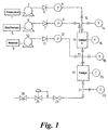
- the reactor comprises two reservoirs, 1 and 5, for the liquid precursors and a reservoir 9, for a substrate.
- High-pressure pumps 2, 6 and 10 are each provided with a non-return valve 3, 7 and 11 respectively and a pressure monitor, 4, 8 and 12 respectively, in order to charge the reactor with the precursors and the substrate.
- Two heated catalytic chambers 15 and 19 are provided, each having a temperature monitoring apparatus 16 and 20 respectively.
- first cruciform pipework intersection shown schematically at 13.
- Mixing of the precursors before introduction to the catalyst bed is avoided by use of internal pipework.
- the temperature of the input of the precursors is monitored by temperature monitor 14.
- the inlet pipework of one precursor may direct the one precursor away from an introduced stream of a second precursor.
- the product output from catalyst chamber enters a T-shaped pipework intersection 21, where its temperature is monitored by temperature monitor 22.
- the output product can be tapped off at sample collector 25.
- a back pressure regulator 24 is fitted between the tap 23 and sample collector 25, in order to maintain a constant pressure within the reactor.
- Chamber 15 is a gas-production chamber
- chamber 19 is a chemical reactor chamber in which the gases react with the substrate.
- the gas mixture produced may not take part in the reaction - for example it may be a supercritical fluid or dense phase gas solvent in which reactions of other chemicals occurs.
- Examples 1 and 2 below illustrate the use of supercritical fluids according to the present invention in the hydrogenation of trans-cinnamaldehyde and the effect of changing the flow rates of the precursors (formic acid and ethyl formate) on the yield of the desired product (hydrocinnamaldehyde) and on the amount of by-product (3-phenyl-1-propenol).
- the equipment was set up as shown in Figure 1.
- the catalyst chamber 1 (15) was charged with Deloxan AP II (Pt) 5% and maintained at a temperature of 400°C (16).
- Catalyst chamber 2 (19) was charged with Deloxan AP II (Pd) 5% and maintained at a temperature of 180°C (20).
- Formic acid and ethyl formate (precursor materials) were each charged to separate pumps (2 and 6) and entered catalyst chamber 1 (15) at flow rates of 0.2 and 0.2 ml/min respectively.
- the pressure of the reactor was maintained at 200 bar by means of back pressure regulator (24). At this temperature and pressure a supercritical liquid or dense phase fluid is formed (carbon dioxide, hydrogen, and ethane).
- Trans-cinnamaldehyde was charged to the substrate pump (10) from the reservoir. This was pumped into catalyst chamber 2 (19) at a flow rate of 0.05 ml/min. A solution containing the product was collected from the exit of the back pressure regulator (24) in an ice-cooled vial (25). Analysis of the solution by gas chromatography and 1 H NMR spectroscopy showed that the product was hydrocinnamaldehyde and that the yield was 65%. Gas chromatography and NMR analysis identified a yield of 30% of a second product, 3-phenyl-1-propenol.
- the equipment was set up as shown in Figure 1.
- the catalyst chamber 1 (15) was charged with Deloxan AP II (Pt) 5% and maintained at a temperature of 400°C (16).
- Catalyst chamber 2 (19) was charged with Deloxan AP II (Pd) 5% and maintained at a temperature of 180°C (20).
- Formic acid and ethyl formate were each charged to separate pumps (2 and 6) and entered catalyst chamber 1 (15) at flow rates of 0.1 and 0.4 ml/min respectively.
- the pressure of the reactor was maintained at 200 bar by means of a back pressure regulator (24).
- Trans-cinnamaldehyde was charged to the substrate pump (10). This was pumped into catalyst chamber 2 (19) at a flow rate of 0.05 ml/min.
- a solution containing the product was collected from the exit of the back pressure regulator (24) in an ice cooled vial (25). Analysis of the solution by gas chromatography and 1 H NMR spectroscopy showed that the product was hydrocinnamaldehyde and that the yield was 90%. Gas Chromatography and NMR analysis identified a yield of only 5% of a second product, 3-phenyl-1-propenol. Thus, changing the precursor flow-rates resulted in significant improvement in the yield of the desired product.
- the equipment was set up as in Figure 1.
- the catalyst chamber 1 (15) was charged with Deloxan AP II (Pt) 5% and maintained at a temperature of 400C (16).
- Catalyst chamber 2 (19) was charged with Deloxan AP II (Pd) 5% and maintained at a temperature of 80°C (20).
- Formic acid was charged to pump (2) and entered catalyst chamber 1 (15) at a flow rate of 0.2 ml/min.
- the pressure of the reactor was maintained at 80 bar by means of a back pressure regulator (24). Cyclohexene was charged to the substrate pump (10). This was pumped into catalyst chamber 2 (19) at a flow rate of 0.5 ml/min.
- a solution containing the product was collected from the exit of the back pressure regulator (24) in an ice cooled vial (25). Analysis of the solution by gas chromatography and 1 H NMR spectroscopy showed that the product was cyclohexane and that the yield was 100%.
- the equipment was set up as in Figure 1 and maintained.
- the catalyst chamber 1 (15) was charged with Deloxan AP II (Pt) 5% and maintained at a temperature of 400C (16).
- Catalyst chamber 2 (19) was charged with Amberlyst-15 TM and maintained at a temperature of 180C (20).
- Ethyl formate was charged to pump (6) and entered catalyst chamber 1 (15) at a flow rate of 0.4 ml/min.
- the pressure of the reactor was maintained at 200 bar by means of a back pressure regulator (24). 1,4-butanediol was charged to the substrate pump (10). This was pumped into chamber 2 (19) at a flow rate of 0.5 ml/min.
- the equipment was set up as in Figure 1.
- the catalyst chamber 1 (15) was charged with Deloxan AP II (Pt) 5% and maintained at a temperature of 400°C (16).
- Catalyst chamber 2 (19) was charged with Deloxan AP II (Pd) 5% and maintained at a temperature of 100°C (20).
- Formic acid was charged to pump (2) and entered catalyst chamber 1 (15) at a flow rate of 0.4 ml/min.
- the pressure of the reactor was maintained at 120 bar by means of a back pressure regulator (24).
- Trans-cinnamaldehyde was charged to the substrate pump (10). This was pumped into catalyst chamber 2 (19) at a flow rate of 0.05 ml/min.
- a solution was collected from the exit of the back pressure regulator (24) in an ice-cooled vial (25). Analysis of the solution by gas chromatography and NMR spectroscopy showed that no reaction had occurred.
- the equipment was set up as in Figure 1.
- the catalyst chamber 1 (15) was charged with Deloxan AP II (Pt) 5% and maintained at a temperature of 400°C (16).
- Catalyst chamber 2 (19) was charged with Deloxan AP II (Pd) 5% and maintained at a temperature of 100°C (20).
- Formic acid was charged to pump (2) and allowed to enter catalyst chamber 1 (15) at flow rate of 0.4 ml/min.
- the pressure of the reactor was maintained at 150 bar by means of a back pressure regulator (24).
- Trans-cinnamaldehyde was charged to the substrate pump (10). This was pumped into catalyst chamber 2 (19) at a flow rate of 0.05 ml/min.
- a solution containing the product was collected from the exit of the back pressure regulator (24) in an ice-cooled vial (25). Analysis of the solution by gas chromatography and NMR spectroscopy showed that the product was hydrocinnamaldehyde and that the yield was 38%.
- the equipment was set up as in Figure 1.
- the catalyst chamber 1 (15) was charged with Deloxan AP II (Pt) 5% and held at a temperature of 400C (16).
- Catalyst chamber 2 (19) was charged with Nafion SAC-13 and held at a temperature of 200C (20).
- Ethyl Formate was charged to pump (2) and allowed to enter catalyst chamber 1 (15) at a flow rate of 0.4 mL/min.
- the pressure of the cell was maintained at 100 bar by means of a backpressure regulator (24). 1,3,5-trimethylbezene was charged to the substrate pump (10). This was pumped into chamber 2 (19) at a flow rate of 0.05 mL/min.
- the equipment was set up as in Figure 1.
- the catalyst chamber 1 (15) was charged with Deloxan AP II (Pt) 5% and held at a temperature of 400C (16).
- Catalyst chamber 2 (19) was charged with Nafion SAC-13 and held at a temperature of 200C (20).
- Ethyl formate was charged to pump (2) and allowed to enter catalyst chamber 1 (15) at flow rate of 0.4 mL/min.
- the pressure of the cell was maintained at 300 bar by means of a back pressure regulator (24).
- M-cresol was charged to the substrate pump (10). This was pumped into chamber 2 (19) at a flow rate of 0.01 mL/min.
- a solution containing the product was collected from the exit of the back pressure regulator (24) in an ice cooled vial (25). Analysis of the solution by gas chromatography and 1 H NMR spectroscopy showed that the product was 3-methyl, 4-isopropyphenol as the only product and the yield was 30%.
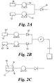
- Figure 2A shows two precursor liquids 50 and 52 being metered and provided by precursor supply control meters 54 and 56 and shows the two liquids mixing before non-return valve 58. This may be permissible if the two liquids do not react together, or if they do react together but the reaction products are indeed what is wanted for introduction to the reaction chamber.
- Figure 2B shows two liquids 50' and 52' mixing after passing through respective non-return valves 58' and 60. This prevents any contamination of the liquids 50' and 52' in liquid reservoirs 62 and 64.
- Figure 2C schematically shows a precursor liquid 70 in a precursor liquid reservoir 72, where the liquid 70 is made of two different liquid substances, schematically shown as 74 and 76.
- the liquids 74 and 76 may be miscible or immiscible.
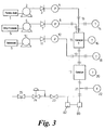
- Figure 3 shows a micro-production facility similar to that of Figure 1, except that it has a gas liquid chromatograph (GLC) 80 which takes an on-line sample of what is being produced and analyses it. An infrared spectrometer 82 is also shown taking an on-line sample for on-line analysis.
- GLC gas liquid chromatograph
- the GLC and/or IR spectrometer could be at a different place in the production line, and/or samples from more than one place in the reaction sequences could be analysed.
- Figure 4 shows a micro-reactor plant 90 having a reaction chamber 92, precursor liquids 94, 96, 98 held in reservoirs 95, 97 and 99, metering pumps 100, 102, 104, pressure sensors 106, 108, 110, precursor inflow lines 112, 114, 116 leading to chamber 92, a pressure sensor 118 in chamber 92, a temperature controller 120 to control the temperature in chamber 92, a temperature sensor 122 in chamber 92, a back pressure regulator/pressure controller 124 controlling the pressure in chamber 92, a product collection reservoir 126, a gas/liquid chromatograph 128, an infrared spectrometer 130, and a microprocessor controller 132.
- the controller 132 receives sensor signals from the sensors and output control signals to the pumps 100, 102, 104, the temperature controller 120, the pressure regulator 124, and the IR and GLC 128 and 130.
- the IR and GLC also provide information/analysis signals to the processor 132.
- the total volume of the chamber 92 and pipe work from reservoirs 92, 96, 98 to the chamber 92 is about 5ml.
- the processor 132 can be programmed by a user to pump a known and carefully controlled amount of precursors 94, 96 and 98 (sometimes different amounts of each, sometimes the amounts may be the same) to the chamber 92 where the liquid precursors become gaseous.
- the pressure and temperature in chamber 92 is such that gaseous precursor materials, or their reaction products, become supercritical fluids.
- Chemical reaction occurs in the chamber 92, the course of the reactions occurring in chamber 92 being controlled by the temperature, pressure, and amounts of precursor allowed into the chamber.
- the reaction products are analysed in an on-line process, which may be continuous, by IR and/or GLC.
- the processor 132 can control conditions responsive to the feedback it receives from the sensors.
- the processor 132 may be programmable by a user to produce different, selectable, reaction products, possibly from the same starting precursors, or possibly using different precursor substances.
- This method may also be conveniently used to convert Paraformaldahyde (CHO) n to CO + H 2 , (an industrially important gas mixture known as Syngas).
- the ratio of CO to H 2 may be varied in Syngas for different purposes. Different customers want a different mix.
- the ratio of CO to H 2 can be easily varied by judicious use and combination of two or more of the following reactions; (1) (CHO) n ⁇ CO + H 2 (2) HCOOH ⁇ H 2 O + CO. (3) Indeed, any liquid ⁇ X + H 2 (4) or liquid ⁇ Y + CO which can be used to vary the amount of H 2 versus CO in the resulting mixture of gases.
- the proportions of the liquid precursors we can vary the ratio of the resultant components within the gas mixture.
- HCOOC 2 H 5 ⁇ CO 2 + C 2 H 6 is interesting because ethane has a relatively low critical point.
- HCOOC 2 H 5 specifically to create a supercritical ethane / carbon dioxide mixture. This mixture can be used as a vehicle for chemical reactions, or drying biological materials, to name but two uses.
- Figure 5A shows a chemical reactor 200 having a gas-production chamber 202 and a chemical reaction chamber 204.
- a liquid precursor 206 to a gas is introduced to the chamber 204 via port 208.
- a substance 210 is introduced to the chamber 202 via port 212.
- the gas produced from the precursor 206 and the substance 210 flow into the reaction chamber 204 where a chemical reaction takes place.
- the chamber 204 typically, but not always, has a catalyst 214 to facilitate the chemical reaction.
- a reaction product 216 leaves the chamber 204 via port 218.
- the substance 210 may be a liquid precursor to a gas, or a gas itself, or a liquid, or a solid.
- the chemical reaction in chamber 204 preferably takes place in the supercritical fluid or dense phase gas state.
- the gas/substance mixture (or compound or mixture of compounds if they react) is preferably in the supercritical fluid or dense phase gas state in the chamber 202 and/or chamber 204.
- the liquid precursor 206 may be involved in the chemical reaction in the chamber 204, or it may not.
- the substance 210 may be involved in the chemical reaction or it may not (either of the gas from the precursor 206 or the substance may simply be a supercritical fluid /dense phase gas).
- Figure 5B shows a reactor 220 that is similar to that of Figure 5A, except that no substance 210 is introduced. Similar components have been given similar reference numerals.
- FIG. 5C shows a variant on the chemical reactor arrangement.
- Reactor 230 has a first gas production chamber 202a and a second gas production chamber 202b.
- the chamber 202a receives liquid precursor 206".
- the chamber 202b receives a substance 210", which may be a gas, or a liquid precursor which experiences a chemical change to become a gas, or it may be a liquid which experiences a physical change to become a gas.
- Gas from chambers 202a and 202b mix in pipework 232 and a chemical substrate 234 is introduced at or prior to a chemical reactor 204".
- Figure 5D shows a variant discussed above where the substance 210" of Figure 5C is itself a liquid precursor, precursor 206(b), and precursor 206" is also a liquid precursor (206a), both liquid precursors experiencing a chemical change to produce different gases or gas mixtures which are mixed prior to (or in some cases after) the introduction of a chemical substrate 234"'.
- the reactors comprise supercritical or dense phase fluid chemical reactors adapted to synthesise chemicals.
- One way of looking at some embodiments of the invention is that we can provide supercritical fluids without gases as the starting point.
- a gas or mixture of gases is produced by decomposition or chemical reaction of liquid precursor(s) which is converted to a dense phase or supercritical fluid state which can be used as a medium for chemical reactions. Changes in the gas composition may be made simply by modification of the metered flow rates or chemical composition of the liquid precursor(s).
- the invention is performed, preferably, in a continuous flow reactor.
Landscapes
- Chemical & Material Sciences (AREA)
- Organic Chemistry (AREA)
- Chemical Kinetics & Catalysis (AREA)
- Organic Low-Molecular-Weight Compounds And Preparation Thereof (AREA)
- Solid-Sorbent Or Filter-Aiding Compositions (AREA)
- Extraction Or Liquid Replacement (AREA)
- Manufacturing Of Micro-Capsules (AREA)
- Physical Or Chemical Processes And Apparatus (AREA)
Claims (28)
- Verwendung eines chemischen Reaktors für superkritische Fluid- oder Dichte-Phasen-Fluid-Medien, aufweisend
ein Reaktionsgefäß, geeignet zur Durchführung chemischer Reaktionen in Dichte-Phasen oder superkritischen Fluiden;
einen Gasgenerator umfassend einen Einlass für flüssigen chemischen Vorläufer, einen Gastransportkanal von dem Gaskanal zu dem Reaktionsgefäß; und
zumindest ein Vorratsgefäß für flüssigen chemischen Vorläufer, der mit dem Einlass in Verbindung steht,
um Gas durch eine chemische Reaktion oder Zerlegung eines oder mehrerer flüssiger chemischer Vorläufer in dem Gasgeneratorgefäß zu erzeugen, und Verwendung des auf diese Weise erzeugten Gases in einer superkritischen Fluid- oder Dichte-Phasen-Fluid-Reaktion. - Verwendung eines Reaktors nach Anspruch 1, wobei eine Mischung aus Gasen durch chemische Reaktion oder Zerlegung eines oder mehrerer flüssiger chemischer Vorläufer erzeugt wird.
- Verwendung eines Reaktors nach Anspruch 2, wobei die Gasmischung mit einer gesteuerten Zusammensetzung erzeugt wird.
- Verwendung eines Reaktors nach Anspruch 1, Anspruch 2 oder Anspruch 3, wobei ein zusätzliches Mittel zur Materialeinführung in dem Reaktionsgefäß bereit gestellt ist, das geeignet ist, die Einführung eines zusätzlichen Materials zu erlauben.
- Verwendung eines Reaktors nach irgendeinem der vorstehende Ansprüche umfassend einen Hydrogenator.
- Verwendung eines Reaktors nach irgendeinem der vorstehende Ansprüche, wobei ein Mikroprozessor oder eine Steuerung zur Verfügung steht, um die Temperatur und den Druck in der Kammer oder dem Gefäß zu steuern und um die Versorgung der einen oder mehreren flüssigen Vorläufer in dem Gasgenerator zu steuern.
- Verwendung eines Reaktors nach irgendeinem der vorstehende Ansprüche, wobei ein Drucksteuerungsmittel zur Verfügung steht, das geeignet ist, um einen Druck in der Kammer oder dem Reaktionsgefäß und/oder dem Gasgenerator zu erzeugen, der größer ist als der Atmosphärendruck.
- Verwendung eines Reaktors nach Anspruch 6, wobei das Drucksteuerungsmittel einen Gegendruckregler umfasst.
- Verwendung eines Reaktors nach irgendeinem der vorstehenden Ansprüche, wobei ein Temperatursteuerungsmittel zur Verfügung steht, das geeignet ist, eine Temperatur zu erzeugen, die höher als 15 Grad Celsius ist.
- Verwendung eines Reaktors nach irgendeinem der vorstehenden Ansprüche, ausgestattet mit einem Analysemittel, das geeignet ist, die Zusammensetzung von Materialien zu analysieren.
- Verwendung eines Reaktors nach irgendeinem der vorstehende Ansprüche, wobei ein Mittel zur Steuerung der relativen Mengen an Substanz(en), die in die Kammer eingeführt wird/werden, zur Verfügung steht.
- Verwendung eines Reaktors nach Anspruch 6 oder irgend einem Anspruch, der direkt oder indirekt von Anspruch 6 anhängig ist, wobei der Mikroprozessor oder die Steuerung durch den Anwender steuerbar ist, um den Reaktor zu veranlassen, eine Gasmischung mit einer ausgewählten Zusammensetzung zu erzeugen.
- Verwendung eines Reaktors nach Anspruch 12, wobei es mehr als einen flüssigen Vorläufer gibt und wobei die Zusammensetzung der erzeugten Gasmischung gesteuert wird, indem die relativen Mengen des flüssigen Vorläufers gesteuert werden, die in den Gasgenerator eingeführt werden.
- Verfahren zur Durchführung einer superkritischen oder Dichte-Phasen-Reaktion, umfassend die Schritte:Bevorraten eines oder mehrerer flüssiger chemischer Vorläufer für ein Gas in flüssiger Form;Umwandeln des flüssigen chemischen Vorläufers in das Gas, wobei das Gas das Produkt einer chemischen Reaktion oder einer Zerlegung des flüssigen chemischen Vorläufers ist undVerwenden des erzeugten Gases in einer superkritischen oder Dichte-Phasen-Reaktion, wobei der/die flüssige(n) chemische(n) Vorläufer im Wesentlichen während einer Zeit des Bedarfs nach dem Gas in das Gas umgewandelt wird/umgewandelt werden.
- Verfahren zur Durchführung einer superkritischen oder Dichte-Phasen-Reaktion nach Anspruch 14, wobei eine Mischung von Gasen mit Gaskomponenten aus dem einen oder mehreren flüssigen chemischen Vorläufer(n) erzeugt wird.
- Verfahren nach Anspruch 15, wobei die Zusammensetzung der erzeugten Gasmischung gesteuert wird.
- Verfahren nach irgendeinem der Ansprüche 14 bis 16, wobei das Gas oder die Mischung von Gasen in eine Kammer eingeführt wird, in der der Druck und die Temperatur in der Kammer derart sind, dass eine Dichte-Phase-Gas oder ein superkritisches Fluid gebildet wird.
- Verfahren nach irgendeinem der Ansprüche 14 bis 17, wobei das Gas oder zumindest eine der Gaskomponenten ein Zerlegungsprodukt eines flüssigen Vorläufermoleküls von höherem Molekulargewicht ist.
- Verfahren nach irgendeinem der Ansprüche 15 bis 18, wobei es eine Vielzahl unterschiedlicher flüssiger chemischer Vorläufer gibt, von denen sich jeder in eine gasförmige Komponente einer Gasmischung umwandelt.
- Verfahren nach Anspruch 19, wobei die Zusammensetzung der erzeugten Gasmischung durch Steuern der relativen Mengen an flüssigen Vorläufern gesteuert wird.
- Verfahren nach irgendeinem der Ansprüche 14 bis 20, wobei das erzeugte Gas oder eine der erzeugten Gaskomponenten eines oder mehrere aus Wasserstoff, Kohlendioxid, Kohlenmonoxid, Methan und Ethan ist.
- Verfahren nach irgendeinem der Ansprüche 14 bis 21, wobei die ausgeführte superkritische oder Dichte-Phasen-Reaktion irgendeine aus Hydrogenierung, Friedel-Crafts-Acylierung oder -Alkylierung, Umesterung, Veretherung, Hydrogenolyse, Entschützung und Zyklisierung ist.
- Verfahren nach irgendeinem der Ansprüche 14 bis 22, wobei zumindest ein flüssiger chemischer Vorläufer des Gases oder einer Gaskomponente aus der Gruppe umfassend:- organische Säuren, Ester einer organischen Säure, Formiat, Karbonat oder Salz einer der vorgenannten Substanzen stammt.
- Verfahren nach irgendeinem der Ansprüche 14 bis 23, wobei der flüssige chemische Vorläufer einen oder zumindest einen von(i) HCOOH(ii) HCOOC2H5(iii) HCOOCH3(iv) HCOOC3H7(v) (CHO)n, wobei n größer oder gleich ist als eins(vi) H2O2umfasst.
- Verfahren nach irgendeinem der Ansprüche 14 bis 24, wobei der flüssige chemische Gasvorläufer eine Mischung aus Ameisensäure und Ethylformiat umfasst.
- Verfahren nach irgendeinem der Ansprüche 14 bis 25, wobei eine Vielzahl von flüssigen chemischen Gasvorläufern aus der Liste:(i) HCOOH(ii) HCOOC2H5(iii) HCOOCH3(iv) HCOOC3H7(v) (CHO)n, wobei n größer oder gleich ist als eins(vi) H2O2bereitgestellt wird.
- Verfahren nach irgendeinem der Ansprüche 14 bis 26, wobei die flüssige chemische Vorläuferflüssigkeit zerlegt oder chemisch abreagiert wird, um das Gas oder zumindest eine der Gaskomponenten zu bilden.
- Verfahren nach irgendeinem der Ansprüche 14 bis 27, wobei der/die flüssige(n) chemische(n) Vorläufer über einem Katalysator reagieren, um das Gas oder die zumindest eine der Gaskomponente(n) zu bilden.
Applications Claiming Priority (3)
| Application Number | Priority Date | Filing Date | Title |
|---|---|---|---|
| GBGB0108151.2A GB0108151D0 (en) | 2001-03-31 | 2001-03-31 | Supercritical fluids formed from liquid precursors |
| GB0108151 | 2001-03-31 | ||
| PCT/GB2002/001246 WO2002078832A2 (en) | 2001-03-31 | 2002-04-02 | Supercritical fluids or dense phase gases formed from liquid precursors |
Publications (2)
| Publication Number | Publication Date |
|---|---|
| EP1377366A2 EP1377366A2 (de) | 2004-01-07 |
| EP1377366B1 true EP1377366B1 (de) | 2007-03-21 |
Family
ID=9912024
Family Applications (1)
| Application Number | Title | Priority Date | Filing Date |
|---|---|---|---|
| EP02718287A Expired - Lifetime EP1377366B1 (de) | 2001-03-31 | 2002-04-02 | Superkritische fluide oder dichte gasphasen aus flüssigen vorläufern |
Country Status (7)
| Country | Link |
|---|---|
| US (1) | US20040146449A1 (de) |
| EP (1) | EP1377366B1 (de) |
| AT (1) | ATE357287T1 (de) |
| AU (1) | AU2002249356A1 (de) |
| DE (1) | DE60218993D1 (de) |
| GB (1) | GB0108151D0 (de) |
| WO (1) | WO2002078832A2 (de) |
Families Citing this family (1)
| Publication number | Priority date | Publication date | Assignee | Title |
|---|---|---|---|---|
| CN102557076B (zh) * | 2010-12-08 | 2015-06-24 | 联仕(上海)电子化学材料有限公司 | 一种生产电子级氟化铵水溶液的方法 |
Family Cites Families (1)
| Publication number | Priority date | Publication date | Assignee | Title |
|---|---|---|---|---|
| GB9620745D0 (en) * | 1996-10-04 | 1996-11-20 | Swan Thomas & Co Ltd | Alkylation and acylation reactions |
-
2001
- 2001-03-31 GB GBGB0108151.2A patent/GB0108151D0/en not_active Ceased
-
2002
- 2002-04-02 AU AU2002249356A patent/AU2002249356A1/en not_active Abandoned
- 2002-04-02 AT AT02718287T patent/ATE357287T1/de not_active IP Right Cessation
- 2002-04-02 DE DE60218993T patent/DE60218993D1/de not_active Expired - Lifetime
- 2002-04-02 WO PCT/GB2002/001246 patent/WO2002078832A2/en not_active Ceased
- 2002-04-02 EP EP02718287A patent/EP1377366B1/de not_active Expired - Lifetime
- 2002-04-02 US US10/473,556 patent/US20040146449A1/en not_active Abandoned
Also Published As
| Publication number | Publication date |
|---|---|
| WO2002078832A3 (en) | 2002-11-21 |
| US20040146449A1 (en) | 2004-07-29 |
| WO2002078832A2 (en) | 2002-10-10 |
| DE60218993D1 (de) | 2007-05-03 |
| ATE357287T1 (de) | 2007-04-15 |
| EP1377366A2 (de) | 2004-01-07 |
| AU2002249356A1 (en) | 2002-10-15 |
| GB0108151D0 (en) | 2001-05-23 |
Similar Documents
| Publication | Publication Date | Title |
|---|---|---|
| CN100415637C (zh) | 从氧化烃低温生产氢 | |
| Devetta et al. | Kinetic experiments and modeling of a three-phase catalytic hydrogenation reaction in supercritical CO2 | |
| Zhu et al. | Flow chemistry-enabled studies of rhodium-catalyzed hydroformylation reactions | |
| AU2022211902B2 (en) | Hydrogenation process | |
| Robinson et al. | Kinetics of the catalytic vapor phase carbonylation of methanol to acetic acid | |
| Kröcher et al. | Sol–gel derived hybrid materials as heterogeneous catalysts for the synthesis of N, N-dimethylformamide from supercritical carbon dioxide | |
| Liu et al. | Chemical kinetics of hydroxylation of phenol catalyzed by TS-1/diatomite in fixed-bed reactor | |
| JPH10245201A (ja) | 炭化水素基質の接触部分酸化方法および装置 | |
| Moehmel et al. | New catalytic materials for the high-temperature synthesis of hydrocyanic acid from methane and ammonia by high-throughput approach | |
| Schwiderowski et al. | Probing the methanol-assisted autocatalytic formation of methanol over Cu/ZnO/Al 2 O 3 by high-pressure methanol and methyl formate pulses | |
| US5198589A (en) | Cobalt carbonyl catalyzed olefin hydroformylation in supercritical carbon dioxide | |
| EP1377366B1 (de) | Superkritische fluide oder dichte gasphasen aus flüssigen vorläufern | |
| Jiang et al. | Synthesis of higher alcohols from syngas over Zn–Cr–K catalyst in supercritical fluids | |
| KR102500508B1 (ko) | 사이클로도데센의 제조 방법 및 이의 합성 장치 | |
| AU2005240413A1 (en) | A flow-type laboratory hydrogenation apparatus and a laboratory hydrogenation process using the apparatus. | |
| van der Laan et al. | Liquid-phase methanol synthesis in apolar (squalane) and polar (tetraethylene glycol dimethylether) solvents | |
| Ashraf et al. | Continuous-flow liquid-phase dehydrogenation of 1, 4-cyclohexanedione in a structured multichannel reactor | |
| Müller et al. | Novel continuous catalytic hydrogenation process for the synthesis of diacetone-d-allose | |
| Au et al. | Nonuniform activity distribution in catalyst particles: Benzene hydrogenation on supported nickel in a single pellet diffusion reactor | |
| EP4426672A1 (de) | HETEROGENES KATALAYST MIT EINEM ÜBERGANGSMETALL AUF EINEM SULFONSÄUREFUNKTIONALISIERTEN SiO2 -TRÄGER UND VERWENDUNG EINES SOLCHEN KATALYSATORS IN EINEM VERFAHREN ZUR HERSTELLUNG EINES ETHERS | |
| EP4237398A1 (de) | Verfahren zur herstellung eines ethers | |
| JP5110561B2 (ja) | 超臨界二酸化炭素反応方法及び装置 | |
| Vijayaraghavan et al. | Mini-Pilot Plant Design Amd Operation of a Liquid Entrained Reactor for Liquid Phase Methanol Synthesis Process | |
| WO2006134401A1 (en) | Multi-phase reactions | |
| Westerterp et al. | The catalytic hydrogenation of 2, 4-dinitrotoluene in a continuous stirred three-phase slurry reactor with an evaporating solvent |
Legal Events
| Date | Code | Title | Description |
|---|---|---|---|
| PUAI | Public reference made under article 153(3) epc to a published international application that has entered the european phase |
Free format text: ORIGINAL CODE: 0009012 |
|
| 17P | Request for examination filed |
Effective date: 20031029 |
|
| AK | Designated contracting states |
Kind code of ref document: A2 Designated state(s): AT BE CH CY DE DK ES FI FR GB GR IE IT LI LU MC NL PT SE TR |
|
| AX | Request for extension of the european patent |
Extension state: AL LT LV MK RO SI |
|
| 17Q | First examination report despatched |
Effective date: 20040628 |
|
| GRAP | Despatch of communication of intention to grant a patent |
Free format text: ORIGINAL CODE: EPIDOSNIGR1 |
|
| GRAS | Grant fee paid |
Free format text: ORIGINAL CODE: EPIDOSNIGR3 |
|
| GRAA | (expected) grant |
Free format text: ORIGINAL CODE: 0009210 |
|
| AK | Designated contracting states |
Kind code of ref document: B1 Designated state(s): AT BE CH CY DE DK ES FI FR GB GR IE IT LI LU MC NL PT SE TR |
|
| PG25 | Lapsed in a contracting state [announced via postgrant information from national office to epo] |
Ref country code: AT Free format text: LAPSE BECAUSE OF FAILURE TO SUBMIT A TRANSLATION OF THE DESCRIPTION OR TO PAY THE FEE WITHIN THE PRESCRIBED TIME-LIMIT Effective date: 20070321 Ref country code: FI Free format text: LAPSE BECAUSE OF FAILURE TO SUBMIT A TRANSLATION OF THE DESCRIPTION OR TO PAY THE FEE WITHIN THE PRESCRIBED TIME-LIMIT Effective date: 20070321 Ref country code: NL Free format text: LAPSE BECAUSE OF FAILURE TO SUBMIT A TRANSLATION OF THE DESCRIPTION OR TO PAY THE FEE WITHIN THE PRESCRIBED TIME-LIMIT Effective date: 20070321 Ref country code: CH Free format text: LAPSE BECAUSE OF FAILURE TO SUBMIT A TRANSLATION OF THE DESCRIPTION OR TO PAY THE FEE WITHIN THE PRESCRIBED TIME-LIMIT Effective date: 20070321 Ref country code: BE Free format text: LAPSE BECAUSE OF FAILURE TO SUBMIT A TRANSLATION OF THE DESCRIPTION OR TO PAY THE FEE WITHIN THE PRESCRIBED TIME-LIMIT Effective date: 20070321 Ref country code: LI Free format text: LAPSE BECAUSE OF FAILURE TO SUBMIT A TRANSLATION OF THE DESCRIPTION OR TO PAY THE FEE WITHIN THE PRESCRIBED TIME-LIMIT Effective date: 20070321 |
|
| REG | Reference to a national code |
Ref country code: GB Ref legal event code: FG4D |
|
| REG | Reference to a national code |
Ref country code: CH Ref legal event code: EP |
|
| REF | Corresponds to: |
Ref document number: 60218993 Country of ref document: DE Date of ref document: 20070503 Kind code of ref document: P |
|
| REG | Reference to a national code |
Ref country code: IE Ref legal event code: FG4D |
|
| PG25 | Lapsed in a contracting state [announced via postgrant information from national office to epo] |
Ref country code: SE Free format text: LAPSE BECAUSE OF FAILURE TO SUBMIT A TRANSLATION OF THE DESCRIPTION OR TO PAY THE FEE WITHIN THE PRESCRIBED TIME-LIMIT Effective date: 20070621 |
|
| PG25 | Lapsed in a contracting state [announced via postgrant information from national office to epo] |
Ref country code: DE Free format text: LAPSE BECAUSE OF FAILURE TO SUBMIT A TRANSLATION OF THE DESCRIPTION OR TO PAY THE FEE WITHIN THE PRESCRIBED TIME-LIMIT Effective date: 20070622 |
|
| PG25 | Lapsed in a contracting state [announced via postgrant information from national office to epo] |
Ref country code: ES Free format text: LAPSE BECAUSE OF FAILURE TO SUBMIT A TRANSLATION OF THE DESCRIPTION OR TO PAY THE FEE WITHIN THE PRESCRIBED TIME-LIMIT Effective date: 20070702 |
|
| PG25 | Lapsed in a contracting state [announced via postgrant information from national office to epo] |
Ref country code: PT Free format text: LAPSE BECAUSE OF FAILURE TO SUBMIT A TRANSLATION OF THE DESCRIPTION OR TO PAY THE FEE WITHIN THE PRESCRIBED TIME-LIMIT Effective date: 20070821 |
|
| REG | Reference to a national code |
Ref country code: CH Ref legal event code: PL |
|
| NLV1 | Nl: lapsed or annulled due to failure to fulfill the requirements of art. 29p and 29m of the patents act | ||
| EN | Fr: translation not filed | ||
| PLBE | No opposition filed within time limit |
Free format text: ORIGINAL CODE: 0009261 |
|
| STAA | Information on the status of an ep patent application or granted ep patent |
Free format text: STATUS: NO OPPOSITION FILED WITHIN TIME LIMIT |
|
| PG25 | Lapsed in a contracting state [announced via postgrant information from national office to epo] |
Ref country code: DK Free format text: LAPSE BECAUSE OF FAILURE TO SUBMIT A TRANSLATION OF THE DESCRIPTION OR TO PAY THE FEE WITHIN THE PRESCRIBED TIME-LIMIT Effective date: 20070321 |
|
| 26N | No opposition filed |
Effective date: 20071227 |
|
| PG25 | Lapsed in a contracting state [announced via postgrant information from national office to epo] |
Ref country code: GR Free format text: LAPSE BECAUSE OF FAILURE TO SUBMIT A TRANSLATION OF THE DESCRIPTION OR TO PAY THE FEE WITHIN THE PRESCRIBED TIME-LIMIT Effective date: 20070622 Ref country code: IT Free format text: LAPSE BECAUSE OF FAILURE TO SUBMIT A TRANSLATION OF THE DESCRIPTION OR TO PAY THE FEE WITHIN THE PRESCRIBED TIME-LIMIT Effective date: 20070321 Ref country code: FR Free format text: LAPSE BECAUSE OF FAILURE TO SUBMIT A TRANSLATION OF THE DESCRIPTION OR TO PAY THE FEE WITHIN THE PRESCRIBED TIME-LIMIT Effective date: 20071123 |
|
| PG25 | Lapsed in a contracting state [announced via postgrant information from national office to epo] |
Ref country code: IE Free format text: LAPSE BECAUSE OF NON-PAYMENT OF DUE FEES Effective date: 20070402 |
|
| PG25 | Lapsed in a contracting state [announced via postgrant information from national office to epo] |
Ref country code: FR Free format text: LAPSE BECAUSE OF FAILURE TO SUBMIT A TRANSLATION OF THE DESCRIPTION OR TO PAY THE FEE WITHIN THE PRESCRIBED TIME-LIMIT Effective date: 20070321 |
|
| PGFP | Annual fee paid to national office [announced via postgrant information from national office to epo] |
Ref country code: GB Payment date: 20080409 Year of fee payment: 7 |
|
| PG25 | Lapsed in a contracting state [announced via postgrant information from national office to epo] |
Ref country code: MC Free format text: LAPSE BECAUSE OF NON-PAYMENT OF DUE FEES Effective date: 20070430 |
|
| PG25 | Lapsed in a contracting state [announced via postgrant information from national office to epo] |
Ref country code: CY Free format text: LAPSE BECAUSE OF FAILURE TO SUBMIT A TRANSLATION OF THE DESCRIPTION OR TO PAY THE FEE WITHIN THE PRESCRIBED TIME-LIMIT Effective date: 20070321 |
|
| PG25 | Lapsed in a contracting state [announced via postgrant information from national office to epo] |
Ref country code: LU Free format text: LAPSE BECAUSE OF NON-PAYMENT OF DUE FEES Effective date: 20070402 |
|
| PG25 | Lapsed in a contracting state [announced via postgrant information from national office to epo] |
Ref country code: TR Free format text: LAPSE BECAUSE OF FAILURE TO SUBMIT A TRANSLATION OF THE DESCRIPTION OR TO PAY THE FEE WITHIN THE PRESCRIBED TIME-LIMIT Effective date: 20070321 |
|
| GBPC | Gb: european patent ceased through non-payment of renewal fee |
Effective date: 20090402 |
|
| PG25 | Lapsed in a contracting state [announced via postgrant information from national office to epo] |
Ref country code: GB Free format text: LAPSE BECAUSE OF NON-PAYMENT OF DUE FEES Effective date: 20090402 |