EP1377130A2 - Microwave oven, and guide roller, cooking tray and dish for use in microwave oven - Google Patents
Microwave oven, and guide roller, cooking tray and dish for use in microwave oven Download PDFInfo
- Publication number
- EP1377130A2 EP1377130A2 EP02256991A EP02256991A EP1377130A2 EP 1377130 A2 EP1377130 A2 EP 1377130A2 EP 02256991 A EP02256991 A EP 02256991A EP 02256991 A EP02256991 A EP 02256991A EP 1377130 A2 EP1377130 A2 EP 1377130A2
- Authority
- EP
- European Patent Office
- Prior art keywords
- microwave oven
- guide roller
- absorbing pad
- cooking
- cooking tray
- Prior art date
- Legal status (The legal status is an assumption and is not a legal conclusion. Google has not performed a legal analysis and makes no representation as to the accuracy of the status listed.)
- Withdrawn
Links
Images



Classifications
-
- F—MECHANICAL ENGINEERING; LIGHTING; HEATING; WEAPONS; BLASTING
- F24—HEATING; RANGES; VENTILATING
- F24C—DOMESTIC STOVES OR RANGES ; DETAILS OF DOMESTIC STOVES OR RANGES, OF GENERAL APPLICATION
- F24C15/00—Details
- F24C15/16—Shelves, racks or trays inside ovens; Supports therefor
-
- H—ELECTRICITY
- H05—ELECTRIC TECHNIQUES NOT OTHERWISE PROVIDED FOR
- H05B—ELECTRIC HEATING; ELECTRIC LIGHT SOURCES NOT OTHERWISE PROVIDED FOR; CIRCUIT ARRANGEMENTS FOR ELECTRIC LIGHT SOURCES, IN GENERAL
- H05B6/00—Heating by electric, magnetic or electromagnetic fields
- H05B6/64—Heating using microwaves
- H05B6/6408—Supports or covers specially adapted for use in microwave heating apparatus
- H05B6/6411—Supports or covers specially adapted for use in microwave heating apparatus the supports being rotated
Definitions
- the present invention relates to microwave ovens, and guide rollers, cooking trays and dishes for use in microwave ovens.
- a microwave oven is an electrically operated oven which cooks food therein by repeatedly exciting molecular bonds of moisture in the food using high-frequency electromagnetic waves.
- the high-frequency electromagnetic waves generated from a magnetron of the microwave oven generate intermolecular frictional heat within the food.
- the high-frequency electromagnetic waves are generated from an antenna assembly of the magnetron, which is provided in an electric component compartment of the microwave oven, and are introduced into a cooking chamber through a waveguide of the microwave oven.
- Figure 1 shows an internal structure, i.e., a cooking chamber 101 of a conventional microwave oven described above.
- the cooking chamber 101 is provided on its side wall with a wave-emitting area 105, which allows the high-frequency electromagnetic waves generated from the antenna assembly (not shown) of the magnetron (not shown) to be introduced into the cooking chamber 101.
- the cooking chamber 101 is provided on its bottom with a roller guide 102 with rollers 102a, which is adapted to rotate about a driving protrusion 104.
- the rollers 102a are partially inserted in an annular groove formed on the bottom surface of the cooking chamber 101.
- a cooking tray 103 is placed on the guide roller 102, and is centrally provided at its lower surface with rotating protrusions (not shown), which engage with the driving protrusion 104.
- a user places a dish with food placed thereon on the cooking tray 103, and closes a door (not shown) of the microwave oven. Subsequently, the user inputs information, such as a desired cooking condition, and turns the microwave oven on. At this point, high-frequency electromagnetic waves generated from the magnetron are introduced into the cooking chamber 101.
- the driving protrusion 104 provided on the bottom of the microwave oven is then rotated, and the cooking tray 103 is supplied with rotating force from the driving protrusion 104 where the rotating protrusions of the cooking tray 103 engage with the driving protrusion 104.
- the cooking tray 103 is rotated to achieve even cooking of the food.
- the microwave oven is provided with the guide roller 102 with the rollers 102a, between its bottom panel and the cooking tray 103, to reduce a frictional force of the bottom panel and to balance the cooking tray 103. Accordingly, the cooking tray 103 is smoothly rotated about the driving protrusion 104. At this point, since the rollers 102a provided at the guide roller 102 are partially inserted in the annular roller groove formed on the bottom panel of the microwave oven, the guide roller 102 rotates in place while maintaining its horizontal position. Therefore, the food placed on the cooking tray 103 is rotated at a certain angular velocity, thereby allowing the food to be evenly cooked.
- the guide rollers 102 and the cooking trays 103 of the conventional microwave oven are made of, for example, glass, and are only used to rotate the food placed thereon.
- the degree of absorption of the electromagnetic waves is not considered, and as a result the food may not be evenly cooked.
- a microwave oven comprising: a microwave generator to generate microwaves; a cooking chamber into which the generated microwaves are introduced; and an absorbing pad which is provided in the cooking chamber and arranged to absorb high-frequency electromagnetic waves including the generated microwaves.
- the absorbing pad is provided at a lower portion of the cooking chamber.
- the absorbing pad is detachably provided to the cooking chamber.
- the microwave oven further comprises a guide roller which is provided in a lower portion of the cooking chamber arranged to guide rotation of food disposed thereover, wherein the absorbing pad is attached to the guide roller.
- the absorbing pad is detachably attached to the guide roller.
- the microwave oven further comprises a guide roller which is provided in a lower portion of the cooking chamber arranged to guide rotation of food disposed thereover, wherein the guide roller is made of a material which absorbs high-frequency electromagnetic waves and comprises the absorbing pad.
- the microwave oven further comprises a cooking tray provided in a lower portion of the cooking chamber, wherein the absorbing pad is attached to the cooking tray.
- the absorbing pad is detachably attached to the cooking tray.
- the microwave oven further comprises a cooking tray provided in a lower portion of the cooking chamber, wherein the cooking tray is made of a material which absorbs high-frequency electromagnetic waves and comprises the absorbent pad.
- the absorbent pad is made of a material select from a group comprising of ferrite, polypropylene, polyphenylene sulfide, polytetrafluoroethylene and polysulfone.
- the absorbing pad evenly cooks food.
- the microwave oven further comprises a driving protrusion which is provided in a lower portion of the cooking chamber and supplies a rotating force; and a cooking tray having a rotating protrusion which engages with the driving protrusion, wherein the cooking tray rotates in response to the rotating force of the driving protrusion.
- the absorbing pad is detachably attached to the cooking tray.
- the microwave oven further comprises an annular groove formed on the lower portion of the cooking chamber, wherein the annular groove has a predetermined radius relative to the driving protrusion; and a guide roller which is placed below the cooking tray and guide to a rotation of the cooking tray, wherein: the guide roller includes rollers which are provided at a periphery of the guide roller, and the annular groove partially receives the rollers so as to have the guide roller rotate about the predetermined radius.
- a guide roller for use in a microwave oven, the guide roller comprising an absorbing pad attached to the guide roller, wherein the absorbing pad absorbs high-frequency electromagnetic waves, and the guide roller guides a rotation of food disposed thereover.
- the absorbing pad is detachably attached to the guide roller.
- a cooking tray for use in a microwave oven, the cooking tray comprising an absorbing pad, wherein the absorbing pad absorbs high-frequency electromagnetic waves, and the cooking tray seats food thereon.
- the absorbing pad is attached to the cooking tray.
- the cooking tray is made of a material which absorbs high-frequency electromagnetic waves and forms the absorbing pad.
- a dish to be placed on a cooking tray of a microwave oven, the dish comprising an absorbing pad, wherein the absorbing pad absorbs high-frequency electromagnetic waves, and the dish seats food thereon.
- the absorbing pad is attached to the dish.
- the dish is made of a material which absorbs high-frequency electromagnetic waves, and forms the absorbing pad.
- the guide roller, the cooking tray, and the dish may comprise an absorbing pad made of a material selected from a group comprising ferrite, polypropylene, polyphenylene sulfide, polytetrafluoroethylene and polysulfone.
- FIG 2 shows an exploded perspective view of components provided in a microwave oven according to an embodiment of the present invention.
- the microwave oven is centrally provided at its bottom panel 200 with a driving protrusion 205 which supplies a force required to rotate food during a cooking operation.
- the bottom panel 200 is further formed with an annular roller groove 206 having a certain radius relative to the driving protrusion 205.
- the annular roller groove 206 partially receives rollers 202a provided at a periphery of a guide roller 202, such that the guide roller 202 is stably rotated about its centre.
- the guide roller 202 is centrally perforated to form a through hole.
- a circular absorption pad 203 is detachably attached to an upper surface of the guide roller 202 by its holding pieces 203a, and absorbs high-frequency electromagnetic waves.
- the absorption pad 203 can be selectively detached from the guide roller 202 if required.
- a cooking tray 204 is placed on the guide roller 202, and allows food (not shown) or a dish with the food to be placed thereon.
- the cooking tray 204 is provided at its lower surface with rotating protrusions 204a, which engage with the driving protrusion 205 of the bottom panel 200 to receive the rotating force of the driving protrusion 205.
- FIG 3 shows a plan view of the bottom panel of the microwave oven, in which the cooking tray 204 is removed to clearly display the absorption pad 203.
- the absorption pad 203 is detachably attached to the guide roller 202 by holding pieces 203a. Although the holding pieces 203a are shown as hooks for simplicity of the structure, it is understood that other holding structures may be employed.
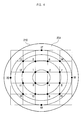
- Figure 4 shows the cooking tray 204 having a mashed potato 210 placed thereon, and on which a coordinate is plotted to show experimental results of the present invention.
- the mashed potato 210 (a mixture of a crushed potato, butter, oil, water, etc.) is evenly spread on the cooking tray 204 at a thickness of 4 cm.
- the mashed potato 210 is first cooked under output electric power of 1174.9 W, an electric current of 17.76 A and for an operating period of about 10 minutes, without attaching the absorption pad 203 to the guide roller 202.
- black dots positioned on circles, and numerals corresponding to the black dots designate positions at which respective temperatures of the cooked mashed potato 210 are measured. The temperatures at the corresponding dots are represented in Celsius and Fahrenheit.
- the temperatures of the mashed potato 210 in areas corresponding to the dots 5 to 12 exhibit relatively lower values than that of areas corresponding to the dots 17 to 20.
- the standard deviation between the temperatures measured at the dots is calculated to be relatively high at 7.2°C (12.9 °F).
- regions of the mashed potato 210 corresponding to the dots 17 to 20 are relatively quickly cooked while regions of the mashed potato 210 corresponding to the dots 5 to 12 are relatively slowly cooked. This means that there are insufficiently cooked regions and excessively cooked regions after elapse of a desired cooking time.
- the absorption pads 203 may be made by moulding a composition which has excellent properties in thermal resistance. That is, materials including polypropylene, polyphenylene sulfide, polytetrafluoroethylene, polysulfone, etc., can be used as an absorption pad 203 to absorb the high-frequency electromagnetic waves. It is believed that the high-frequency electromagnetic waves exhibit absorption for compositions such as the ferrite, polypropylene, polyphenylene sulfide, polytetrafluoroethylene and polysulfone. Of the above, ferrite is known to have the best absorption effect.
- temperatures of the mashed potato 210 in areas corresponding to the dots 5 to 12 exhibit relatively lower values than that of areas corresponding to the dots 17 to 20, as in the case without the absorption pad 203.
- temperatures measured at the respective dots of the mashed potato 210 are higher at almost all regions. This means that a time period required to cook food can be shortened where the absorption pad 203 is used/attached to the guide roller 202.
- the standard deviation between the temperatures measured at all the dots is calculated to be 4.7°C (8.4°F), which is considerably lower than the standard deviation of 7.2°C (12.9 °F) obtained without the use of the absorption pad 203. Therefore, the experiments show that the food is more evenly cooked with the use of the absorption pad 203.
- FIG. 5 shows a cooking tray 204 with an absorption pad 203 attached thereto according to another embodiment of the present invention. While the absorption pad 203 is attached to an upper surface of the cooking tray 204, it is understood that the term “attached” is to be broadly construed to include cases where the absorption pad 203 is provided at the upper surface or a lower surface of the cooking tray 204, within the cooking tray 204, or any combination thereof.
- the cooking tray 104 may also be wholly made of an absorption material which absorbs the high-frequency electromagnetic waves.
- the absorption pad 203 may also be attached to a dish (not shown) to be placed on the cooking tray 204 to evenly cook food placed therein/thereon. Again, the absorption pad 203 may be provided at an upper surface of the dish, a lower surface of the dish, within the dish, or any combination thereof.
- the dish itself may be made of the absorption material to absorb the high-frequency electromagnetic waves.
- a microwave oven has been described, having a pad which absorbs high-frequency electromagnetic waves attached to a guide roller and/or a cooking tray of the microwave oven, and/or to a dish for use in the microwave oven, so as to be heated by the electromagnetic waves and thereby evenly cook food.
- a time period required to cook the food can be reduced as compared to a conventional microwave oven using the same electric power. Accordingly, an amount of electric energy require to cook the food is reduced. Furthermore, it is possible to prevent warping of a container due to temperature differences by overheating during or after an operation of the microwave oven.
Landscapes
- Physics & Mathematics (AREA)
- Electromagnetism (AREA)
- Engineering & Computer Science (AREA)
- Chemical & Material Sciences (AREA)
- Combustion & Propulsion (AREA)
- Mechanical Engineering (AREA)
- General Engineering & Computer Science (AREA)
- Electric Ovens (AREA)
- Cookers (AREA)
Abstract
A guide roller (202), a cooking tray (204) and a dish for use in a microwave oven are provided with a pad (203) which absorbs high-frequency electromagnetic waves, so as to evenly cook food disposed therein or thereon. The microwave oven includes the pad (203) provided in its cooking chamber to absorb the high-frequency electromagnetic waves. The pad (203) may be attached to the guide roller (202), the cooking tray (204), the dish for use in the microwave oven, or any combination thereof. Alternatively, the guide roller (202), the cooking tray (204), the dish, or any combination thereof may be made of a material which absorbs the high-frequency electromagnetic waves.
Description
- The present invention relates to microwave ovens, and guide rollers, cooking trays and dishes for use in microwave ovens.
- Generally, a microwave oven is an electrically operated oven which cooks food therein by repeatedly exciting molecular bonds of moisture in the food using high-frequency electromagnetic waves. The high-frequency electromagnetic waves generated from a magnetron of the microwave oven generate intermolecular frictional heat within the food. The high-frequency electromagnetic waves are generated from an antenna assembly of the magnetron, which is provided in an electric component compartment of the microwave oven, and are introduced into a cooking chamber through a waveguide of the microwave oven.
- Figure 1 shows an internal structure, i.e., a
cooking chamber 101 of a conventional microwave oven described above. - As shown in Figure 1, the
cooking chamber 101 is provided on its side wall with a wave-emitting area 105, which allows the high-frequency electromagnetic waves generated from the antenna assembly (not shown) of the magnetron (not shown) to be introduced into thecooking chamber 101. Thecooking chamber 101 is provided on its bottom with aroller guide 102 withrollers 102a, which is adapted to rotate about adriving protrusion 104. Therollers 102a are partially inserted in an annular groove formed on the bottom surface of thecooking chamber 101. Acooking tray 103 is placed on theguide roller 102, and is centrally provided at its lower surface with rotating protrusions (not shown), which engage with thedriving protrusion 104. An operation of such a conventional microwave oven will now be described. - To use such a conventional microwave oven, a user places a dish with food placed thereon on the
cooking tray 103, and closes a door (not shown) of the microwave oven. Subsequently, the user inputs information, such as a desired cooking condition, and turns the microwave oven on. At this point, high-frequency electromagnetic waves generated from the magnetron are introduced into thecooking chamber 101. Thedriving protrusion 104 provided on the bottom of the microwave oven is then rotated, and thecooking tray 103 is supplied with rotating force from thedriving protrusion 104 where the rotating protrusions of thecooking tray 103 engage with thedriving protrusion 104. Thecooking tray 103 is rotated to achieve even cooking of the food. - The microwave oven is provided with the
guide roller 102 with therollers 102a, between its bottom panel and thecooking tray 103, to reduce a frictional force of the bottom panel and to balance thecooking tray 103. Accordingly, thecooking tray 103 is smoothly rotated about thedriving protrusion 104. At this point, since therollers 102a provided at theguide roller 102 are partially inserted in the annular roller groove formed on the bottom panel of the microwave oven, theguide roller 102 rotates in place while maintaining its horizontal position. Therefore, the food placed on thecooking tray 103 is rotated at a certain angular velocity, thereby allowing the food to be evenly cooked. - It is believed that the electromagnetic waves exhibit complete reflection for conductors, and transmission for articles such as glass products. The
guide rollers 102 and thecooking trays 103 of the conventional microwave oven are made of, for example, glass, and are only used to rotate the food placed thereon. The degree of absorption of the electromagnetic waves is not considered, and as a result the food may not be evenly cooked. - It is an aim of preferred embodiments of the present invention to provide a microwave oven having a guide roller and/or a cooking tray, and a dish for use in the microwave oven, which are capable of allowing food disposed thereon to be evenly cooked.
- Additional aims and advantages of the invention will be set forth in part in the description which follows and, in part, will be apparent from the description, or may be learned by practice of the invention.
- According to a first aspect of the present invention there is provided a microwave oven comprising: a microwave generator to generate microwaves; a cooking chamber into which the generated microwaves are introduced; and an absorbing pad which is provided in the cooking chamber and arranged to absorb high-frequency electromagnetic waves including the generated microwaves.
- Preferably, the absorbing pad is provided at a lower portion of the cooking chamber.
- Preferably, the absorbing pad is detachably provided to the cooking chamber.
- Preferably, the microwave oven further comprises a guide roller which is provided in a lower portion of the cooking chamber arranged to guide rotation of food disposed thereover, wherein the absorbing pad is attached to the guide roller.
- Preferably, the absorbing pad is detachably attached to the guide roller.
- Preferably, the microwave oven further comprises a guide roller which is provided in a lower portion of the cooking chamber arranged to guide rotation of food disposed thereover, wherein the guide roller is made of a material which absorbs high-frequency electromagnetic waves and comprises the absorbing pad.
- Preferably, the microwave oven further comprises a cooking tray provided in a lower portion of the cooking chamber, wherein the absorbing pad is attached to the cooking tray.
- Preferably, the absorbing pad is detachably attached to the cooking tray.
- Preferably, the microwave oven further comprises a cooking tray provided in a lower portion of the cooking chamber, wherein the cooking tray is made of a material which absorbs high-frequency electromagnetic waves and comprises the absorbent pad.
- Preferably, the absorbent pad is made of a material select from a group comprising of ferrite, polypropylene, polyphenylene sulfide, polytetrafluoroethylene and polysulfone.
- Preferably, the absorbing pad evenly cooks food.
- Preferably, the microwave oven further comprises a driving protrusion which is provided in a lower portion of the cooking chamber and supplies a rotating force; and a cooking tray having a rotating protrusion which engages with the driving protrusion, wherein the cooking tray rotates in response to the rotating force of the driving protrusion.
- Preferably, the absorbing pad is detachably attached to the cooking tray.
- Preferably, the microwave oven further comprises an annular groove formed on the lower portion of the cooking chamber, wherein the annular groove has a predetermined radius relative to the driving protrusion; and a guide roller which is placed below the cooking tray and guide to a rotation of the cooking tray, wherein: the guide roller includes rollers which are provided at a periphery of the guide roller, and the annular groove partially receives the rollers so as to have the guide roller rotate about the predetermined radius.
- According to a second aspect of the present invention there is provided a guide roller for use in a microwave oven, the guide roller comprising an absorbing pad attached to the guide roller, wherein the absorbing pad absorbs high-frequency electromagnetic waves, and the guide roller guides a rotation of food disposed thereover.
- Preferably, the absorbing pad is detachably attached to the guide roller.
- According to a third aspect of the present invention there is provided a cooking tray for use in a microwave oven, the cooking tray comprising an absorbing pad, wherein the absorbing pad absorbs high-frequency electromagnetic waves, and the cooking tray seats food thereon.
- Preferably, the absorbing pad is attached to the cooking tray.
- Preferably, the cooking tray is made of a material which absorbs high-frequency electromagnetic waves and forms the absorbing pad.
- According to a fourth aspect of the present invention there is provided a dish to be placed on a cooking tray of a microwave oven, the dish comprising an absorbing pad, wherein the absorbing pad absorbs high-frequency electromagnetic waves, and the dish seats food thereon.
- Preferably, the absorbing pad is attached to the dish.
- Preferably, the dish is made of a material which absorbs high-frequency electromagnetic waves, and forms the absorbing pad.
- The guide roller, the cooking tray, and the dish may comprise an absorbing pad made of a material selected from a group comprising ferrite, polypropylene, polyphenylene sulfide, polytetrafluoroethylene and polysulfone.
- For a better understanding of the invention, and to show how embodiments of the same may be carried into effect, reference will now be made, by way of example, to the accompanying diagrammatic drawings in which:
- Figure 1 is a front view illustrating an internal structure of a cooking chamber of a conventional microwave oven;
- Figure 2 is an exploded perspective view of components installed in a microwave oven according to an embodiment of the present invention;
- Figure 3 is a top plan view of a guide roller of the present invention having a pad which absorbs high-frequency electromagnetic waves;
- Figure 4 a plan view of a cooking tray of the present invention having a mashed potato placed thereon, and on which a coordinate is plotted to show experimental results of the present invention; and
- Figure 5 is a perspective view of a cooking tray having a pad which absorbs the high-frequency electromagnetic waves according to another embodiment of the present invention.
- Figure 2 shows an exploded perspective view of components provided in a microwave oven according to an embodiment of the present invention. As shown in Figure 2, the microwave oven is centrally provided at its
bottom panel 200 with adriving protrusion 205 which supplies a force required to rotate food during a cooking operation. Thebottom panel 200 is further formed with anannular roller groove 206 having a certain radius relative to thedriving protrusion 205. Theannular roller groove 206 partially receivesrollers 202a provided at a periphery of aguide roller 202, such that theguide roller 202 is stably rotated about its centre. Theguide roller 202 is centrally perforated to form a through hole. Acircular absorption pad 203 is detachably attached to an upper surface of theguide roller 202 by itsholding pieces 203a, and absorbs high-frequency electromagnetic waves. Theabsorption pad 203 can be selectively detached from theguide roller 202 if required. Acooking tray 204 is placed on theguide roller 202, and allows food (not shown) or a dish with the food to be placed thereon. Thecooking tray 204 is provided at its lower surface with rotatingprotrusions 204a, which engage with thedriving protrusion 205 of thebottom panel 200 to receive the rotating force of thedriving protrusion 205. - Figure 3 shows a plan view of the bottom panel of the microwave oven, in which the
cooking tray 204 is removed to clearly display theabsorption pad 203. Theabsorption pad 203 is detachably attached to theguide roller 202 byholding pieces 203a. Although theholding pieces 203a are shown as hooks for simplicity of the structure, it is understood that other holding structures may be employed. - Figure 4 shows the
cooking tray 204 having amashed potato 210 placed thereon, and on which a coordinate is plotted to show experimental results of the present invention. - For experimental purposes, the mashed potato 210 (a mixture of a crushed potato, butter, oil, water, etc.) is evenly spread on the
cooking tray 204 at a thickness of 4 cm. Themashed potato 210 is first cooked under output electric power of 1174.9 W, an electric current of 17.76 A and for an operating period of about 10 minutes, without attaching theabsorption pad 203 to theguide roller 202. In the drawing, black dots positioned on circles, and numerals corresponding to the black dots, designate positions at which respective temperatures of the cookedmashed potato 210 are measured. The temperatures at the corresponding dots are represented in Celsius and Fahrenheit. The experimental results are shown in the Table 1.Table 1 No. Temperature (C)/(F) NO. Temperature (C)/(F) 1 74.5/166.10 11 64.0/147.20 2 78.8/173.84 12 65.1/149.18 3 66.8/152.24 13 81.9/179.42 4 74.3/165.74 14 80.7/177.26 5 72.0/161.60 15 79.4/174.92 6 74.8/166.46 16 78.3/172.94 7 75.9/168.62 17 84.7/184.46 8 73.1/163.22 18 84.1/183.38 9 66.0/150.80 19 84.4/183.92 10 63.2/145.76 20 83.3/181.94 - As shown in the Table 1, the temperatures of the
mashed potato 210 in areas corresponding to thedots 5 to 12 exhibit relatively lower values than that of areas corresponding to thedots 17 to 20. The standard deviation between the temperatures measured at the dots is calculated to be relatively high at 7.2°C (12.9 °F). In other words, without attaching theabsorption pad 203 to, for example, theguide roller 202, regions of themashed potato 210 corresponding to thedots 17 to 20 are relatively quickly cooked while regions of themashed potato 210 corresponding to thedots 5 to 12 are relatively slowly cooked. This means that there are insufficiently cooked regions and excessively cooked regions after elapse of a desired cooking time. - For comparison, the
mashed potato 210 is spread and cooked under the same conditions as those of the above experiment except that theabsorption pad 203 is attached to theguide roller 202. Theabsorption pads 203 may be made by moulding a composition which has excellent properties in thermal resistance. That is, materials including polypropylene, polyphenylene sulfide, polytetrafluoroethylene, polysulfone, etc., can be used as anabsorption pad 203 to absorb the high-frequency electromagnetic waves. It is believed that the high-frequency electromagnetic waves exhibit absorption for compositions such as the ferrite, polypropylene, polyphenylene sulfide, polytetrafluoroethylene and polysulfone. Of the above, ferrite is known to have the best absorption effect. In this experiment, theabsorption pad 203 made of polypropylene is used. The results of the comparison experiment are shown in the Table 2.Table 2 No. Temperature (C)/(F) NO. Temperature (C)/(F) 1 83.4/182.12 11 74.3/164.12 2 82.7/180.86 12 75.2/167.36 3 76.8/170.24 13 79.9/175.82 4 81.5/178.70 14 80.5/176.90 5 75.0/167.00 15 84.2/183.56 6 76.2/169.16 16 82.5/180.50 7 71.4/160.52 17 85.1/185.18 8 74.6/166.28 18 85.1/185.18 9 77.3/171.14 19 85.9/186.62 10 74.6/166.28 20 85.7/186.26 - As shown in the Table 2, temperatures of the
mashed potato 210 in areas corresponding to thedots 5 to 12 exhibit relatively lower values than that of areas corresponding to thedots 17 to 20, as in the case without theabsorption pad 203. However, in the instant case, temperatures measured at the respective dots of themashed potato 210 are higher at almost all regions. This means that a time period required to cook food can be shortened where theabsorption pad 203 is used/attached to theguide roller 202. In addition, the standard deviation between the temperatures measured at all the dots is calculated to be 4.7°C (8.4°F), which is considerably lower than the standard deviation of 7.2°C (12.9 °F) obtained without the use of theabsorption pad 203. Therefore, the experiments show that the food is more evenly cooked with the use of theabsorption pad 203. - Figure 5 shows a
cooking tray 204 with anabsorption pad 203 attached thereto according to another embodiment of the present invention. While theabsorption pad 203 is attached to an upper surface of thecooking tray 204, it is understood that the term "attached" is to be broadly construed to include cases where theabsorption pad 203 is provided at the upper surface or a lower surface of thecooking tray 204, within thecooking tray 204, or any combination thereof. Thecooking tray 104 may also be wholly made of an absorption material which absorbs the high-frequency electromagnetic waves. Alternatively, theabsorption pad 203 may also be attached to a dish (not shown) to be placed on thecooking tray 204 to evenly cook food placed therein/thereon. Again, theabsorption pad 203 may be provided at an upper surface of the dish, a lower surface of the dish, within the dish, or any combination thereof. On the other hand, the dish itself may be made of the absorption material to absorb the high-frequency electromagnetic waves. - A microwave oven has been described, having a pad which absorbs high-frequency electromagnetic waves attached to a guide roller and/or a cooking tray of the microwave oven, and/or to a dish for use in the microwave oven, so as to be heated by the electromagnetic waves and thereby evenly cook food. With the present microwave oven, a time period required to cook the food can be reduced as compared to a conventional microwave oven using the same electric power. Accordingly, an amount of electric energy require to cook the food is reduced. Furthermore, it is possible to prevent warping of a container due to temperature differences by overheating during or after an operation of the microwave oven.
- Although a few embodiments of the present invention have been shown and described, it will be appreciated by those skilled in the art that changes may be made in these embodiments without departing from the scope of the invention which is defined in the appended claims.
- The reader's attention is directed to all papers and documents which are filed concurrently with or previous to this specification in connection with this application and which are open to public inspection with this specification, and the contents of all such papers and documents are incorporated herein by reference.
- All of the features disclosed in this specification (including any accompanying claims, abstract and drawings), and/or all of the steps of any method or process so disclosed, may be combined in any combination, except combinations where at least some of such features and/or steps are mutually exclusive.
- Each feature disclosed in this specification (including any accompanying claims, abstract and drawings), may be replaced by alternative features serving the same, equivalent or similar purpose, unless expressly stated otherwise. Thus, unless expressly stated otherwise, each feature disclosed is one example only of a generic series of equivalent or similar features.
- The invention is not restricted to the details of the foregoing embodiment(s). The invention extends to any novel one, or any novel combination, of the features disclosed in this specification (including any accompanying claims, abstract and drawings), or to any novel one, or any novel combination, of the steps of any method or process so disclosed.
Claims (23)
- A microwave oven comprising:a microwave generator to generate microwaves;a cooking chamber into which the generated microwaves are introduced; andan absorbing pad (203) which is provided in the cooking chamber and arranged to absorb high-frequency electromagnetic waves including the generated microwaves.
- The microwave oven of claim 1, wherein the absorbing pad (203) is provided at a lower portion of the cooking chamber.
- The microwave oven of claim 1 or 2, wherein the absorbing pad (203) is detachably provided to the cooking chamber.
- The microwave oven of claim 1, 2 or 3, further comprising:a guide roller (202) which is provided in a lower portion of the cooking chamber arranged to guide rotation of food disposed thereover, wherein the absorbing pad (203) is attached to the guide roller (202).
- The microwave oven of claim 4, wherein the absorbing pad (203) is detachably attached to the guide roller (202).
- The microwave oven of any preceding claim, further comprising a guide roller (202) which is provided in a lower portion of the cooking chamber arranged to guide rotation of food disposed thereover, wherein the guide roller (202) is made of a material which absorbs high-frequency electromagnetic waves and comprises the absorbing pad (203).
- The microwave oven of any preceding claim, further comprising a cooking tray (204) provided in a lower portion of the cooking chamber, wherein the absorbing pad (203) is attached to the cooking tray.
- The microwave oven of claim 7, wherein the absorbing pad (203) is detachably attached to the cooking tray.
- The microwave oven of any preceding claim, further comprising a cooking tray (204) provided in a lower portion of the cooking chamber, wherein the cooking tray (204) is made of a material which absorbs high-frequency electromagnetic waves and comprises the absorbent pad (203) .
- The microwave oven of any preceding claim wherein the absorbent pad (203) is made of a material select from a group comprising of ferrite, polypropylene, polyphenylene sulfide, polytetrafluoroethylene and polysulfone.
- The microwave oven of any preceding claim wherein the absorbing pad (203) evenly cooks food.
- The microwave oven of any preceding claim, further comprising:a driving protrusion (205) which is provided in a lower portion of the cooking chamber and supplies a rotating force; anda cooking tray (204) having a rotating protrusion (204a) which engages with the driving protrusion (205), wherein the cooking tray (204) rotates in response to the rotating force of the driving protrusion (205).
- The microwave oven of claim 12, wherein the absorbing pad (203) is detachably attached to the cooking tray.
- The microwave oven of claim 12 or 13, further comprising:an annular groove (206) formed on the lower portion of the cooking chamber, wherein the annular groove (206) has a predetermined radius relative to the driving protrusion (205); anda guide roller (202) which is placed below the cooking tray and guide to a rotation of the cooking tray, wherein:the guide roller (202) includes rollers (202a) which are provided at a periphery of the guide roller (202), and the annular groove (206) partially receives the rollers (202a) so as to have the guide roller (202) rotate about the predetermined radius.
- A guide roller (202) for use in a microwave oven, the guide roller (202) comprising an absorbing pad (203) attached to the guide roller, wherein the absorbing pad (203) absorbs high-frequency electromagnetic waves, and the guide roller (202) guides a rotation of food disposed thereover.
- The guide roller of claim 15, wherein the absorbing pad (203) is detachably attached to the guide roller (202).
- A cooking tray (204) for use in a microwave oven, the cooking tray (204) comprising an absorbing pad (203), wherein the absorbing pad (203) absorbs high-frequency electromagnetic waves, and the cooking tray (204) seats food thereon.
- The cooking tray of claim 17, wherein the absorbing pad (203) is attached to the cooking tray (204).
- The cooking tray of claim 17 or 18, wherein the cooking tray (204) is made of a material which absorbs high-frequency electromagnetic waves and forms the absorbing pad (203).
- A dish to be placed on a cooking tray (204) of a microwave oven, the dish comprising an absorbing pad (203), wherein the absorbing pad (23) absorbs high-frequency electromagnetic waves, and the dish seats food thereon.
- The dish of claim 20, wherein the absorbing pad (203) is attached to the dish.
- The dish of claim 20 or 21, wherein:the dish is made of a material which absorbs high-frequency electromagnetic waves, and forms the absorbing pad (203).
- The guide roller (202) of claim 15 or 16, the cooking tray (204) of any of claims 17 to 19, or the dish of any of claims 20 to 22, wherein the absorbing pad (203) is made of a material selected from a group comprising ferrite, polypropylene, polyphenylene sulfide, polytetrafluoroethylene and polysulfone.
Applications Claiming Priority (2)
| Application Number | Priority Date | Filing Date | Title |
|---|---|---|---|
| KR2002037610 | 2002-06-29 | ||
| KR1020020037610A KR20040002168A (en) | 2002-06-29 | 2002-06-29 | Microwave oven, guide roller, cooking tray and dish |
Publications (1)
| Publication Number | Publication Date |
|---|---|
| EP1377130A2 true EP1377130A2 (en) | 2004-01-02 |
Family
ID=29717732
Family Applications (1)
| Application Number | Title | Priority Date | Filing Date |
|---|---|---|---|
| EP02256991A Withdrawn EP1377130A2 (en) | 2002-06-29 | 2002-10-04 | Microwave oven, and guide roller, cooking tray and dish for use in microwave oven |
Country Status (4)
| Country | Link |
|---|---|
| US (1) | US20040000545A1 (en) |
| EP (1) | EP1377130A2 (en) |
| KR (1) | KR20040002168A (en) |
| CN (1) | CN1465910A (en) |
Families Citing this family (12)
| Publication number | Priority date | Publication date | Assignee | Title |
|---|---|---|---|---|
| US20050184066A1 (en) * | 2003-05-22 | 2005-08-25 | Brooks Joseph R. | Susceptor cooking trays and kits for microwavable food products |
| US20060151490A1 (en) * | 2005-01-07 | 2006-07-13 | Dodge Angela N | Combination microwave oven pedestal and support cooking sheets for microwavable dough products |
| USD538100S1 (en) | 2005-01-07 | 2007-03-13 | Kraft Foods Holdings, Inc. | Microwave oven pedestal |
| USD545125S1 (en) | 2005-01-07 | 2007-06-26 | Kraft Foods Holdings, Inc | Susceptor for microwaveable food |
| BRPI0617109A2 (en) | 2005-08-29 | 2011-07-12 | Du Pont | susceptor assemblies, methods for heating a food product and field guide structures |
| CN101341797B (en) * | 2005-12-19 | 2012-05-30 | 纳幕尔杜邦公司 | Arc-resistant microwave susceptor assembly having overheating protection |
| US8598500B2 (en) * | 2005-12-19 | 2013-12-03 | E I Du Pont De Nemours And Company | Arc-resistant microwave susceptor assembly |
| US8835822B2 (en) * | 2005-12-19 | 2014-09-16 | E I Du Pont De Nemours And Company | Field director assembly having arc-resistant conductive vanes |
| US8618453B2 (en) * | 2005-12-19 | 2013-12-31 | E I Du Pont De Nemours And Company | Microwave susceptor assembly having overheating protection |
| US8367988B2 (en) * | 2005-12-19 | 2013-02-05 | E I Du Pont De Nemours And Company | Field director assembly having overheating protection |
| CN110822493A (en) * | 2019-10-22 | 2020-02-21 | 广东美的厨房电器制造有限公司 | cooking utensils |
| CN110645603A (en) * | 2019-10-22 | 2020-01-03 | 广东美的厨房电器制造有限公司 | Cooking utensil |
Family Cites Families (22)
| Publication number | Priority date | Publication date | Assignee | Title |
|---|---|---|---|---|
| NL7108793A (en) * | 1970-07-06 | 1972-01-10 | ||
| US4210124A (en) * | 1975-12-09 | 1980-07-01 | Bosch-Siemens Hausgerate Gmbh | Dish for holding food to be heated in a microwave cooking chamber |
| DE2555344C3 (en) * | 1975-12-09 | 1980-04-10 | Bosch-Siemens Hausgeraete Gmbh, 7000 Stuttgart | Dish tray for holding food to be heated in the microwave oven |
| JPS6018891B2 (en) * | 1979-07-13 | 1985-05-13 | 株式会社東芝 | Microwave popcorn making container |
| US4398077A (en) * | 1980-10-06 | 1983-08-09 | Raytheon Company | Microwave cooking utensil |
| GB2117925B (en) * | 1982-02-19 | 1986-02-05 | Hitachi Heating Appl | Heating apparatus of thawing sensor controlled type |
| US4486640A (en) * | 1982-11-01 | 1984-12-04 | Raytheon Company | Cooker/baker utensil for microwave oven |
| US4742202A (en) * | 1983-06-20 | 1988-05-03 | The United State Of America As Represented By The Secretary Of The Navy | Microwave apparatus for heating contained liquid |
| US4631379A (en) * | 1984-04-20 | 1986-12-23 | Kabushiki Kaisha Toshiba | High-frequency heating device having rotatable tray and high frequency wave agitator |
| JPS636771A (en) * | 1986-06-27 | 1988-01-12 | 今西金属工業株式会社 | Turn-table driver of microwave oven |
| JPS63108122A (en) * | 1986-10-23 | 1988-05-13 | Yukio Sawara | Oven cooking apparatus for microwave oven |
| JPH01218416A (en) * | 1988-02-25 | 1989-08-31 | Nippon Dry Chem Co Ltd | Electric wave absorbing heating cooker |
| CA1333194C (en) * | 1988-06-14 | 1994-11-22 | Taisuke Morino | High-frequency heating apparatus |
| JPH02133710A (en) * | 1988-11-14 | 1990-05-22 | Tokyo Yogyo Co Ltd | Utensil for microwave oven |
| JPH06282229A (en) * | 1993-01-27 | 1994-10-07 | Unitika Ltd | Anti-theft label |
| KR970005758B1 (en) * | 1994-02-28 | 1997-04-19 | 엘지전자 주식회사 | An automatic measurement system of electrode gap in the electron gun |
| KR970062505A (en) * | 1996-02-08 | 1997-09-12 | 구자홍 | Multi-purpose cooking bowl for microwave oven |
| JPH11260543A (en) * | 1998-03-16 | 1999-09-24 | Matsushita Electric Ind Co Ltd | High frequency heating equipment |
| JPH11270857A (en) * | 1998-03-25 | 1999-10-05 | Matsushita Electric Ind Co Ltd | High frequency heating equipment |
| EP1186209A1 (en) * | 2000-04-17 | 2002-03-13 | Matsushita Electric Industrial Co., Ltd. | High-frequency heating apparatus |
| US7776416B2 (en) * | 2001-08-20 | 2010-08-17 | Cryovac, Inc. | Case-ready package having absorbent pad |
| KR100465191B1 (en) * | 2002-02-06 | 2005-01-13 | 삼성전자주식회사 | Microwave Range |
-
2002
- 2002-06-29 KR KR1020020037610A patent/KR20040002168A/en not_active Ceased
- 2002-09-26 CN CNA021433682A patent/CN1465910A/en active Pending
- 2002-09-30 US US10/259,879 patent/US20040000545A1/en not_active Abandoned
- 2002-10-04 EP EP02256991A patent/EP1377130A2/en not_active Withdrawn
Also Published As
| Publication number | Publication date |
|---|---|
| US20040000545A1 (en) | 2004-01-01 |
| CN1465910A (en) | 2004-01-07 |
| KR20040002168A (en) | 2004-01-07 |
Similar Documents
| Publication | Publication Date | Title |
|---|---|---|
| KR100677739B1 (en) | Scanning conventional microwave oven and method of operating the same | |
| CA1119258A (en) | Effective concurrent microwave heating and electrical resistance heating in a countertop microwave oven | |
| EP0333423B1 (en) | Heat generating container for microwave oven | |
| EP1377130A2 (en) | Microwave oven, and guide roller, cooking tray and dish for use in microwave oven | |
| US9781777B2 (en) | Tray for microwave oven | |
| CN101903705A (en) | Cooker | |
| KR20050029277A (en) | Ovenware for microwave oven | |
| EP1399000A2 (en) | Microwave oven with toaster | |
| EP1541930A1 (en) | Steam oven having an inner casing including a vacuum | |
| EP0348156A2 (en) | Improvements relating to microwave heating | |
| JP2936966B2 (en) | Cooking device | |
| JP2004245426A (en) | Steam cooker | |
| JP2014234932A (en) | Heating cooker | |
| JPH11351576A (en) | microwave | |
| KR100438301B1 (en) | Microwave oven provided with a grill egg device | |
| JPH0235903B2 (en) | DENSHIRENJINOTAMENOCHORYOKINZOKUDAI | |
| JP2005257216A (en) | Microwave oven | |
| JP2006317019A (en) | High frequency cooking device | |
| KR200295964Y1 (en) | Electricity pressure rice cooker by induced electricity heating | |
| JPH09199274A (en) | Microwave thawing heating device | |
| JP2001182945A (en) | Heating cooking appliance for thawing mixed food of different kinds of foodstuffs | |
| JPH1059430A (en) | Container with microwave heating adjustment function and cooking method using it | |
| KR19990006408U (en) | Microwave Cooking Plate | |
| KR19990009702U (en) | Microwave Cooking Support Member | |
| WO2022044719A1 (en) | High frequency heating cooker |
Legal Events
| Date | Code | Title | Description |
|---|---|---|---|
| PUAI | Public reference made under article 153(3) epc to a published international application that has entered the european phase |
Free format text: ORIGINAL CODE: 0009012 |
|
| 17P | Request for examination filed |
Effective date: 20021022 |
|
| AK | Designated contracting states |
Kind code of ref document: A2 Designated state(s): AT BE BG CH CY CZ DE DK EE ES FI FR GB GR IE IT LI LU MC NL PT SE SK TR |
|
| AX | Request for extension of the european patent |
Extension state: AL LT LV MK RO SI |
|
| STAA | Information on the status of an ep patent application or granted ep patent |
Free format text: STATUS: THE APPLICATION HAS BEEN WITHDRAWN |
|
| 18W | Application withdrawn |
Effective date: 20041129 |