EP1376864A1 - Piezoelectric vibration element and piezoelectric filter - Google Patents
Piezoelectric vibration element and piezoelectric filter Download PDFInfo
- Publication number
- EP1376864A1 EP1376864A1 EP02708725A EP02708725A EP1376864A1 EP 1376864 A1 EP1376864 A1 EP 1376864A1 EP 02708725 A EP02708725 A EP 02708725A EP 02708725 A EP02708725 A EP 02708725A EP 1376864 A1 EP1376864 A1 EP 1376864A1
- Authority
- EP
- European Patent Office
- Prior art keywords
- piezoelectric
- oscillator
- thickness
- vibration
- electrode
- Prior art date
- Legal status (The legal status is an assumption and is not a legal conclusion. Google has not performed a legal analysis and makes no representation as to the accuracy of the status listed.)
- Withdrawn
Links
Images






Classifications
-
- H—ELECTRICITY
- H03—ELECTRONIC CIRCUITRY
- H03H—IMPEDANCE NETWORKS, e.g. RESONANT CIRCUITS; RESONATORS
- H03H9/00—Networks comprising electromechanical or electro-acoustic elements; Electromechanical resonators
- H03H9/15—Constructional features of resonators consisting of piezoelectric or electrostrictive material
- H03H9/17—Constructional features of resonators consisting of piezoelectric or electrostrictive material having a single resonator
- H03H9/177—Constructional features of resonators consisting of piezoelectric or electrostrictive material having a single resonator of the energy-trap type
-
- H—ELECTRICITY
- H03—ELECTRONIC CIRCUITRY
- H03H—IMPEDANCE NETWORKS, e.g. RESONANT CIRCUITS; RESONATORS
- H03H9/00—Networks comprising electromechanical or electro-acoustic elements; Electromechanical resonators
- H03H9/02—Details
- H03H9/125—Driving means, e.g. electrodes, coils
- H03H9/13—Driving means, e.g. electrodes, coils for networks consisting of piezoelectric or electrostrictive materials
- H03H9/132—Driving means, e.g. electrodes, coils for networks consisting of piezoelectric or electrostrictive materials characterized by a particular shape
-
- H—ELECTRICITY
- H03—ELECTRONIC CIRCUITRY
- H03H—IMPEDANCE NETWORKS, e.g. RESONANT CIRCUITS; RESONATORS
- H03H9/00—Networks comprising electromechanical or electro-acoustic elements; Electromechanical resonators
- H03H9/46—Filters
- H03H9/54—Filters comprising resonators of piezoelectric or electrostrictive material
- H03H9/56—Monolithic crystal filters
- H03H9/562—Monolithic crystal filters comprising a ceramic piezoelectric layer
-
- H—ELECTRICITY
- H03—ELECTRONIC CIRCUITRY
- H03H—IMPEDANCE NETWORKS, e.g. RESONANT CIRCUITS; RESONATORS
- H03H9/00—Networks comprising electromechanical or electro-acoustic elements; Electromechanical resonators
- H03H9/46—Filters
- H03H9/54—Filters comprising resonators of piezoelectric or electrostrictive material
- H03H9/58—Multiple crystal filters
- H03H9/581—Multiple crystal filters comprising ceramic piezoelectric layers
Definitions
- the present invention relates to piezoelectric oscillators and piezoelectric filters using zinc oxide as a piezoelectric material.
- Piezoelectric oscillators using a bulk wave traveling through a solid includes piezoelectric oscillators employed as a clock source for diversifying electronic apparatuses and piezoelectric filters for extracting frequencies in communications apparatuses. Recently, operating frequency bands of these piezoelectric oscillators are becoming increasingly higher. In these piezoelectric oscillators, thickness vibration such as thickness shear vibration and thickness extension vibration is used as main vibration. In particular, the energy trapping phenomenon which facilitates the suppression of unwanted vibration and retention of the oscillator is often applied. Energy trapping is a phenomenon that vibration energy is confined under a driving electrode formed partially on the main face of the piezoelectric oscillator when a specific piezoelectric material is used and a specific vibration mode such as thickness shear vibration and thickness extension vibration is used. This phenomenon is analyzed in details by Shockley, Onoe and other researchers.
- Fig.19 shows , as an example, the frequency spectrum of the thickness shear oscillator using an X plate of lithium tantalate.
- s_0, s_1, and so on are. a symmetry mode, and a_0, a_1, and so on are an asymmetry mode.
- the electric charge distribution in each mode is indicated near the curve indicating each mode. It is apparent from the electric charge distribution in Fig. 19 that the asymmetry mode such as a_0, a_1 and so on is not electrically excited if the driving electrode is disposed symmetrical to the oscillator. Accordingly, only the symmetry mode such as s_0, s_1, and so on can be electrically taken out.
- the energy-trapping amount ⁇ needs to be set to the value that allows confinement of energy only in the s_0 mode.
- the Japanese Laid-open Patent No. S59-182616 defines that energy-trapping amount ⁇ that confines energy only in the s_0 mode is 1.2 or smaller.
- the amount of frequency drop (f0s - f0) / f0s is mostly dependent on the piezoelectric material and is about 0.1. Accordingly, Patent No. S59-182616 describes that the single s_0 mode is made feasible by setting Le/H to 3.8 or smaller.
- the present invention offers a piezoelectric oscillator using zinc oxide as a piezoelectric material. Unwanted resonance called inharmonic overtone is eliminated by optimizing ratio Le/H of driving electrode length Le to oscillator thickness H in the piezoelectric oscillator using thickness extension vibration or thickness shear vibration as main vibration.
- a ladder-type piezoelectric filter or multi-mode piezoelectric filter is manufactured by employing the piezoelectric oscillator of the present invention.
- These piezoelectric filters demonstrate stable filter characteristic without ripple in a passband because each oscillator features stable characteristic without unwanted resonance.
- Ap pieoelectric oscillator of the present invention using zinc oxide as a piezoelectric material is polarized in a thickness direction of a piezoelectric plate, and uses thickness extension vibration as main vibration.
- ratio Le/H of driving electrode length Le to oscillator thickness H is set between 4 and 13. This achieves stable characteristic by eliminating unwanted resonance between resonance frequency and anti-resonance frequency of the main vibration.
- the piezoelectric oscillator of the present invention sets ratio Le/H of driving electrode length Le to thickness H between 4 and 100 instead of 4 and 13 when thickness H of the oscillator is 16 ⁇ m or thinner. This retains resonance impedance. of the main vibration small even at high frequencies, and achieves stable characteristic without unwanted resonance.
- the piezoelectric oscillator of the present invention uses zinc oxide as a piezoelectric material, is polarized in a length direction of the piezoelectric plate, and uses thickness shear vibration as main vibration.
- ratio Le/H of driving electrode length Le to oscillator thickness H is set between 7 and 23. This achieves stable characteristic by eliminating unwanted resonance between resonance frequency and anti-resonance frequency of the main vibration.
- the piezoelectric oscillator of the present invention sets ratio Le/H of driving electrode length Le to thickness H between 7 and 100 instead of 7 and 23 when oscillator thickness H is 14 ⁇ m or thinner. This retains resonance impedance of the main vibration small even at high frequencies, and achieves stable characteristic without unwanted resonance.
- a piezoelectric filter of the present invention is a ladder-type piezoelectric oscillator which employs at least two or more electrically-coupled piezoelectric oscillators described above.
- Ratio Le/H of driving electrode length Le to oscillator thickness H is designed to be optimal. Since each oscillator features stable characteristic without unwanted resonance, a stable filter characteristic without ripple in a passband is achievable.
- the piezoelectric filter of the present invention is a double-mode piezoelectric filter which employs the piezoelectric oscillator having an optimum ratio of driving electrode length to the oscillator thickness, and using thickness extension vibration as main vibration.
- This piezoelectric filter has a pair of input electrode and output electrode on one main face of the oscillator, and a ground electrode on the other main face.
- Ratio Li/H of input electrode length Li to oscillator thickness H and ratio Lo/H of output electrode length Lo to oscillator thickness H are set between 2 and 5 respectively. This achieves stable filter characteristic without ripple in a passband.
- the piezoelectric filter of the present invention is a double-mode piezoelectric filter which employs the piezoelectric oscillator having optimum ratio Le/H of driving electrode length Le to oscillator thickness H, and using thickness shear vibration as main vibration.
- This piezoelectric filter has a pair of input electrode and output electrode on one main face of the oscillator, and a ground electrode on the other main face.
- Ratio Li/H of input electrode length Li to oscillator thickness H and ratio Lo/H of output electrode length Lo to oscillator thickness H are set between 3.5 and 6.5 respectively. This achieves stable filter characteristic without ripple in a passband.
- the piezoelectric oscillator of the present invention shown in Fig. 1 includes vibrating section 1, driving electrodes 2 provided at positions corresponding to (or facing) each other on top and bottom faces of vibrating section 1, lead electrode 3, and electrode 4 for external draw-out.
- the energy trapping amount increases as the driving electrode length becomes longer, but inharmonic overtone such as the s_1 mode and s_2 mode also begins to satisfy energy trapping condition.
- the s_1 mode and s_2 mode exist between resonance. frequency and anti-resonance frequency of the main vibration and become unwanted resonance.
- the horizontal axis is ratio Le/H of driving electrode length Le to oscillator thickness H
- the vertical axis is normalized frequency f/fOs which is the ratio of resonance frequency f in each vibration mode to cutoff frequency f0s in the non-electrode section.
- Anti-resonance frequency of the main vibration is also shown in Fig. 3. It is apparent from Fig. 3 that the resonance frequency in each vibration mode becomes smaller as Le/H increases.
- the s_1 mode and s_2 mode are not output as signals when Le/H is 10 or below in the s_1 mode and Le/H is 15 or below in the s_2 mode because they do not satisfy the energy-trapping condition.
- the s_1 mode and s_2 mode begin to exist between the resonance frequency and anti-resonance frequency of the main vibration when Le/H is 13 or above in the s_1 mode and Le/H is 21 or above in the s_2 mode respectively.
- unstable action such as jumping of the oscillatory frequency may occur if the oscillator is used as an oscillator.
- Le/H is 13 or below
- Le/H leads to reduced electromechanical coupling coefficient which indicates the conversion efficiency of electric energy and mechanical energy due to insufficient energy trapping amount.
- Le/H of 4 or above is found to achieve preferable characteristic without reducing the electromechanical coupling coefficient too much.
- the piezoelectric oscillator using zinc oxide as a piezoelectric material being polarized in a thickness direction of the piezoelectric plate, and using thickness extension vibration as main vibration demonstrates stable characteristic without unwanted resonance between the resonance frequency and anti-resonance frequency of the main vibration when Le/H is between 4 and 13.
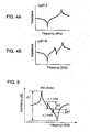
- Figs. 4A and 4B show impedance frequency characteristic of the oscillator when Le/H is 6 and 18 respectively. It is apparent from Fig. 4A that preferable characteristic without unwanted resonance between the resonance frequency and anti-resonance frequency of the main vibration is achieved when Le/H is 6 and within the aforementioned range (i.e., between 4 and 13). For comparison, Fig. 4B shows the case when Le/H is 18, which is out of the aforementioned range. In this case, unwanted resonance equivalent to the s_1 mode exists between the resonance frequency and anti-resonance frequency of the main vibration, degrading the characteristic.
- the frequency stability of the oscillator is better when mechanical quality factor Q which expresses the resonance sharpness of the oscillator is larger.
- Q When the oscillator is used as a filter, it also has a benefit that insert loss becomes smaller. It is known that Q becomes smaller when the operating frequency increases. A level of reduction of Q also differs by vibration mode.
- an area of driving electrode When the oscillator or filter is operated at high frequencies, an area of driving electrode is often enlarged in order to achieve low impedance and high Q. If the area of driving electrode, i.e. driving electrode length, is too large when the operating frequency is low, the resonance frequency of the s_1 mode becomes closer to the resonance frequency of the main vibration, as shown in Fig. 3. If there is not much difference in resonance impedance between these two modes, problems such as jumping of the oscillatory frequency may occur.
- the gain difference between the resonance and anti-resonance of the main vibration is set to G1
- the gain difference between the resonance and anti-resonance of the s_1 mode is set to G2
- the gain difference between the resonance and anti-resonance of the s_2 mode is set to G3 in admittance frequency characteristic of the oscillator.
- the relation between the gain difference in each vibration mode and resonance frequency of the main vibration is investigated as shown in Fig. 6 for the piezoelectric oscillator using zinc oxide as a piezoelectric material, being polarized in a thickness direction of the piezoelectric plate, and using thickness extension vibration as main vibration.
- Le/H is set to 22. It is apparent from Fig. 6 that the gain difference in each vibration mode becomes smaller as the frequency increases because Q reduces and resonance sharpness becomes dull. The level of reduction in gain difference is most obvious in the s_2 mode, and then the s_1 mode. The main vibration has the smallest reduction. It is also apparent from Fig. 6 that 200 MHz or higher resonance frequency is sufficient for the main vibration so as to avoid detrimental effect of unwanted resonance when the gain difference of inharmonic overtone is 1dB or less.
- the frequency constant of the main vibration resonance is about 3100 Hz ⁇ m
- thickness of the oscillator needs to be 16 ⁇ m or thinner in order to achieve 200 MHz or higher resonance frequency for the main vibration. If the oscillator thickness is 16 ⁇ m or thinner, the gain difference in inharmonic overtone is small, and thus almost no detrimental effect of unwanted resonance occurs even Le/H is increased. Accordingly, the resonance impedance in the main vibration can be reduced. If Le/H is increased too much, however, the size of the entire oscillator becomes large, leading to reduced mechanical strength and higher cost. Accordingly, the upper limit of Le/H is set to 100.
- the resonance, impedance in the main vibration is small when oscillator thickness H is 16 ⁇ m or less and Le/H is between 4 and 100 in the piezoelectric oscillator using zinc oxide as a piezoelectric material, being polarized in a thickness direction of the piezoelectric plate, and using thickness extension vibration as main vibration.
- stable characteristic without unwanted resonance between the resonance frequency and anti-resonance frequency of the main vibration is achievable.
- Fig. 7 shows the frequency spectrum of the piezoelectric oscillator using thickness shear vibration as main vibration.
- Le in Fig. 7 shows a long-side length of the driving electrode, and this length direction conforms to the vibrational displacement direction of thickness shear vibration.
- the s_1 mode is not output as signals when Le/H is 13 or less because it does not satisfy the energy trapping condition.
- the s_2 mode is not observed when Le/H is 25 or less.
- the s_1 mode exists between the resonance frequency and anti-resonance frequency of the main vibration when Le/H is 23 or above.
- Le/H is 23 or less.
- the lower limit of Le/H is set to 7 so as to avoid a fall in the electromechanical coupling coefficient.
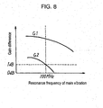
- Fig. 8 shows the relation between the gain difference in the main vibration and each vibration mode of inharmonic overtone and the resonance frequency of the main vibration.
- Le/H is 30. It is apparent from Fig. 8 that the same trend as when thickness extension vibration is used as main vibration is found.
- the gain difference in each vibration mode reduces as the frequency increases.
- the level of reduction in gain difference is larger in the s_1 mode than in the main vibration.
- 100 MHz or higher resonance frequency is sufficient for the main vibration so as to avoid detrimental effect of unwanted resonance when the gain difference in inharmonic overtone is 1dB or less. Since the frequency constant of the main vibration resonance is about 1400 Hz ⁇ m, thickness of the oscillator needs to be 14 ⁇ m or thinner in order to achieve 100 MHz or higher resonance frequency for the main vibration.
- the upper limit of Le/H is set to 100 based on the same reason as that using thickness extension vibration as main vibration. Based on the above results, Le/H needs to be set between 7 and 100 when thickness H of the oscillator is 14 ⁇ m or thinner so as to achieve stable characteristic without unwanted resonance between the resonance frequency and anti-resonance frequency of the main vibration in the piezoelectric oscillator using zinc oxide as a piezoelectric material, being polarized in a length direction of the piezoelectric plate, and using thickness shear vibration as main vibration.
- a band pass filter passing signals in a specific frequency band is manufactureable.
- a ladder-type filter which uses resonance frequency and anti-resonance frequency of the oscillator as a pole of filter characteristic and sets frequencies between the resonance frequency and anti-resonance frequency as a passband is often manufactured. If unwanted resonance exists between the resonance frequency and anti-resonance frequency as characteristic of the oscillator, ripple exists in a passband as the filter characteristic. This results in degrading the characteristic. If the aforementioned oscillators are combined, stable filter characteristic without ripple in a passband is achievable because each oscillator features stable characteristic without unwanted resonance.
- Filters other than ladder-type filters include a multi-mode filter in which multiple piezoelectric oscillators are disposed on one piezoelectric plate and their vibrations are coupled to establish a band pass filter.
- This type of filter is called MCF (monolithic crystal filter); and actively utilizes inharmonic overtone such as the a_0 mode and s_1 mode.
- MCF monolithic crystal filter
- a double-mode filter using two modes of s_0 and a_0 is described below.
- Fig. 9A shows the structure of the double-mode filter.
- a pair of input electrode 8 and output electrode 9 are disposed at a minute distance on one main face of vibrating section 7 of a piezoelectric plate, and ground electrode 10 is disposed on the other main face.
- a band pass filter is created by generating the s_0 mode, which is a symmetry mode, and the a_0 mode, which is an asymmetry mode.
- Figs. 9B and 9C show electric charge distribution in each mode. Only one ground electrode is provided in Fig. 9A, but ground electrode 10 can be provided facing each of input electrode 8 and output electrode 9 as shown in Fig. 10.
- an electrode In order to avoid taking out vibrations, other than those in the s_0 mode or a_0 mode, which become unwanted resonance as electrical signals, an electrode needs to be designed in a way that modes higher that the s_1 mode do no satisfy the energy trapping condition. If the minute distance between input electrode 8 and output electrode 9 is designed as small as to be ignorable compared to input electrode length Li and output electrode length L0, the upper limit of ratio (Li+Lo) /H of the sum (Li+Lo) of input electrode length Li and output electrode length Lo to oscillator thickness H is equivalent to maximum Le/H that the s_1 mode of the oscillator does not satisfy the trapping condition.
- the upper limit of (Li+Lo)/H is 10. If thickness shear vibration is the main vibration, the upper limit is 13.
- the lower limit of (Li+Lo)/H is minimum Le/H which does not reduce the electromechanical coupling coefficient in case of the oscillator. If thickness extension vibration is used as main vibration, the lower limit is 4. If thickness shear vibration is the main vibration, the lower limit is 7.
- the input electrode length and output electrode length are often made the same so as to achieve electrically symmetric I/O characteristic.
- ratio Li/H of input electrode length Li to oscillator thickness H and ratio Lo/H of output electrode length Lo to oscillator thickness H are respectively set between 2 and 5 in order to achieve stable filter characteristic without ripple in the passband.
- Li/H and Lo/H are respectively set between 3.5 and 6.5 in order to achieve stable filter characteristic without ripple in a passband.
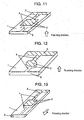
- Fig. 11 is a piezoelectric oscillator which uses zinc oxide as a piezoelectric material, is polarized in a thickness direction of the piezoelectric plate, and uses thickness extension vibration as main vibration.
- This piezoelectric oscillator includes vibrating section 1, driving electrodes 2 disposed at positions facing each other on the top and bottom faces of vibrating section 1, lead electrode 3 and electrode 4 for external draw-out.
- the resonance frequency is about 15 MHz so as to achieve oscillator thickness H of 200 ⁇ m.
- the driving electrode is square with 2 mm for each side. Accordingly, the ratio of the driving electrode length to oscillator thickness is 10. In other words, the ratio falls within the range of 4 to 13, achieving stable characteristic without unwanted resonance between the resonance frequency and anti-resonance frequency of the main vibration.
- Fig. 12 is a piezoelectric oscillator which uses zinc oxide as a piezoelectric material, is polarized in a thickness direction of the piezoelectric plate, and uses thickness extension vibration as main vibration.
- This piezoelectric oscillator includes vibrating 1, driving electrodes 2 disposed at positions facing each other on the top and bottom faces of vibrating section 1, lead electrode 3, and electrode 4 for external draw-out.
- the resonance frequency is about 1.5 GHz because oscillator thickness H is 2 ⁇ m.
- the driving electrode is a round electrode with 60 ⁇ m diameter. Its high operating frequency keeps the gain difference between the resonance and anti-resonance of inharmonic overtone small, achieving preferable characteristic without detrimental effect of unwanted resonance between the resonance frequency and anti-resonance frequency of the main vibration. In addition, low impedance and high Q . for resonance of the main vibration are achievable.
- Fig. 13 is a piezoelectric oscillator which uses zinc oxide as a piezoelectric material, is polarized in a length direction of the piezoelectric plate, and uses thickness shear vibration as main vibration.
- This piezoelectric oscillator includes vibrating section 1, driving electrodes 2 disposed at positions facing each other on the top and bottom faces of vibrating section 1, lead electrode 3, and electrode 4 for external draw-out.
- the resonance frequency is about 7 MHz because oscillator thickness H is 200 ⁇ m.
- Driving electrode length is 3 mm. This makes the ratio of the driving electrode length to oscillator thickness within the range of 7 to 23, achieving stable characteristic without unwanted resonance between the resonance frequency and anti-resonance frequency of the main vibration.
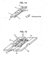
- Fig.14 is a piezoelectric oscillator which uses zinc oxide as a piezoelectric material, is polarized in a length direction of the piezoelectric plate, and uses thickness shear vibration main vibration.
- This piezoelectric oscillator includes vibrating section 1, driving electrodes 2 disposed at positions facing each other on the top and bottom faces of vibrating section 1, lead electrode 3, and electrode 4 for external draw-out.
- the resonance frequency is about 700 MHz since oscillator thickness H is 2 ⁇ m.
- the driving electrode length is 80 ⁇ m, and is formed on the entire width of the oscillator in a width direction: Its high operating frequency keeps the gain difference between the resonance and anti-resonance of inharmonic overtone small, achieving preferable characteristic without detrimental effect of unwanted resonance between the resonance frequency and anti-resonance frequency of the main vibration. In addition, low impedance and high Q for resonance of the main vibration are achievable.
- Fig. 15 is a ladder-type filter configured with two piezoelectric oscillators using zinc oxide as a piezoelectric material, being polarized in a length direction of the piezoelectric plate, and using thickness shear vibration as main vibration.
- This ladder-type filter includes piezoelectric oscillator 11, input external terminal 12, output external terminal 13, ground external terminal 14, conductive resin 15, and mounting board 16.
- Both of oscillators used in the filter have 100 ⁇ m for oscillator thickness H and 1.5 mm for driving electrode length Le. Accordingly the ratio of the driving electrode length to oscillator thickness falls within the range of 7 to 23. This achieves preferable filter characteristic without ripple in a passband because no unwanted resonance exists between the resonance frequency and anti-resonance frequency of the main vibration of each oscillator.
- Fig.16 is a double-mode piezoelectric filter which uses zinc oxide and thickness extension vibration as main vibration.
- This double-mode piezoelectric filter includes vibrating section 7, input electrode 8, output electrode 9, and ground electrode 10.
- the center frequency of the filter is about 62 MHz because oscillator thickness H is 50 ⁇ m.
- Input electrode length Li and output electrode length Lo are both 200 ⁇ m, and thus both ratio Li/H and Lo/H fall 4 which is involved in the range of 2 to 5. Accordingly; a preferable filter characteristic without ripple in a passband is achievable.
- Fig. 17 is a double-mode piezoelectric filter which uses zinc oxide and thickness shear vibration as main vibration.
- This double-mode piezoelectric filter includes vibrating section 7, input electrode 8, output electrode 9, and ground electrode 10.
- the center frequency of the filter is about 35 MHz because oscillator thickness H is 40 ⁇ m.
- Input electrode length Li and output electrode length Lo are both 200 ⁇ m, and thus both ratio Li/H and Lo/H fall 5 which is involved in the range of 3.5 to 6.5. Accordingly, a preferable filter characteristic without ripple in a passband is achievable.
- the present invention aims to offer the oscillator using zinc oxide as a piezoelectric material which does not cause unwanted resonance called inharmonic overtone by optimizing ratio Le/H of driving electrode length Le to oscillator thickness H.
- ratio Le/H of driving electrode length Le to oscillator thickness H is set between 4 and 13 in the piezoelectric oscillator using zinc oxide as a piezoelectric material, being polarized in a thickness direction of the piezoelectric plate, and using thickness extension vibration as main vibration.
- Le/H is set between 7 and 23. This achieves stable characteristic without unwanted resonance between the resonance frequency and anti-resonance frequency of the main vibration.
- a ladder-type piezoelectric filter or multi-mode piezoelectric filter employing the piezoelectric oscillator of the present invention achieves a significant effect of stable filter characteristic without ripple in a passband because each oscillator features stable characteristic without unwanted resonance.
Landscapes
- Physics & Mathematics (AREA)
- Acoustics & Sound (AREA)
- Chemical & Material Sciences (AREA)
- Engineering & Computer Science (AREA)
- Ceramic Engineering (AREA)
- Crystallography & Structural Chemistry (AREA)
- Piezo-Electric Or Mechanical Vibrators, Or Delay Or Filter Circuits (AREA)
Abstract
Description
These piezoelectric filters demonstrate stable filter characteristic without ripple in a passband because each oscillator features stable characteristic without unwanted resonance.
Accordingly, the upper limit of Le/H is set to 100.
This achieves stable characteristic without unwanted resonance between the resonance frequency and anti-resonance frequency of the main vibration.
Claims (9)
- A piezoelectric oscillator comprising:wherein said piezoelectric plate is made of zinc oxide, and dimensional ratio (Le/H) of electrode length (Le) of said driving electrodes facing each other to piezoelectric plate thickness (H) is between 4 and 100.piezoelectric plate (1) anddriving electrodes (2) formed at positions corresponding to each other on both faces of said piezoelectric plate, and
- The piezoelectric oscillator as defined in Claim 1, wherein said piezoelectric plate is polarized in a thickness direction, and uses thickness extension vibration as main vibration; and said dimensional ratio (Le/H) is between 4 and 13.
- The piezoelectric oscillator as defined in Claim 1,. wherein said piezoelectric plate is polarized in a thickness direction, uses thickness extension vibration as main vibration, and has thickness of not greater than 16 µm, and
wherein said dimensional ratio (Le/H) is between 4 and 100. - The piezoelectric oscillator as defined in Claim 2, wherein said piezoelectric oscillator is a piezoelectric filter in which one of said driving electrodes has a pair of input electrode (8) and output electrode (9) and the other electrode is ground electrode (10), and
wherein dimensional ratio Li/H of electrode length (Li) of said input electrode facing said ground electrode to piezoelectric plate thickness (H) and dimensional ratio Lo/H of electrode length (Lo) of said output electrode facing said ground electrode to piezoelectric plate thickness (H) are both between 2 and 5. - The piezoelectric oscillator as defined in Claim 1, wherein said piezoelectric plate is polarized in a length direction, and uses thickness shear vibration as main vibration;, and
wherein said dimensional ratio (Le/H) of long-side driving electrode length (Le) conforming to a vibrational displacement direction to piezoelectric plate thickness (H) is between 7 and 23. - The piezoelectric oscillator as defined in Claim 1, wherein said piezoelectric plate is polarized in a length direction, uses thickness shear vibration as main vibration, and has thickness of not greater than 14µm, and
wherein said dimensional ratio (Le/H) of long-side driving electrode length (Le) conforming to a vibrational displacement direction to piezoelectric plate thickness (H) is between 7 and 100. - The piezoelectric oscillator as defined in Claim 5, wherein said piezoelectric oscillator is a piezoelectric filter in which one of said driving electrodes facing each other has a pair of input electrode and output electrode and the other electrode is a ground electrode, and
wherein dimensional ratio Li/H of electrode length (Li) of said input electrode facing said ground electrode to piezoelectric plate thickness (H) and dimensional ratio Lo/H of electrode length Go) of said output electrode facing said ground electrode to piezoelectric plate thickness (H) are both between 3.5 and 6.5. - A double-mode band-pass piezoelectric filter employing the piezoelectric oscillator defined in one of Claims 4 and 7.
- A band-pass piezoelectric filter combining a plurality of piezoelectric oscillators defined in one of Claims 1, 2, 3, 5, and 6, said piezoelectric filters being configured in a ladder.
Applications Claiming Priority (3)
| Application Number | Priority Date | Filing Date | Title |
|---|---|---|---|
| JP2001103241 | 2001-04-02 | ||
| JP2001103241A JP2002299998A (en) | 2001-04-02 | 2001-04-02 | Piezoelectric vibration element and piezoelectric filter |
| PCT/JP2002/003176 WO2002082646A1 (en) | 2001-04-02 | 2002-03-29 | Piezoelectric vibration element and piezoelectric filter |
Publications (2)
| Publication Number | Publication Date |
|---|---|
| EP1376864A1 true EP1376864A1 (en) | 2004-01-02 |
| EP1376864A4 EP1376864A4 (en) | 2009-05-06 |
Family
ID=18956326
Family Applications (1)
| Application Number | Title | Priority Date | Filing Date |
|---|---|---|---|
| EP02708725A Withdrawn EP1376864A4 (en) | 2001-04-02 | 2002-03-29 | PIEZOELECTRIC VIBRATION ELEMENT AND PIEZOELECTRIC FILTER |
Country Status (4)
| Country | Link |
|---|---|
| US (1) | US7129799B2 (en) |
| EP (1) | EP1376864A4 (en) |
| JP (1) | JP2002299998A (en) |
| WO (1) | WO2002082646A1 (en) |
Families Citing this family (8)
| Publication number | Priority date | Publication date | Assignee | Title |
|---|---|---|---|---|
| US7466067B2 (en) * | 2004-11-01 | 2008-12-16 | Brother Kogyo Kabushiki Kaisha | Piezoelectric actuator, method for producing piezoelectric actuator, liquid transporting apparatus, and method for producing liquid transporting apparatus |
| WO2007029280A1 (en) * | 2005-03-28 | 2007-03-15 | Murata Manufacturing Co., Ltd. | Thickness longitudinal piezoelectric resonator |
| JP2009094829A (en) * | 2007-10-10 | 2009-04-30 | Murata Mfg Co Ltd | Piezoelectric vibration device, oscillation circuit, and electronic apparatus |
| KR101843190B1 (en) | 2011-08-31 | 2018-03-28 | 삼성전기주식회사 | Ceramic electronic component and method for manufacturing the same |
| JP6079280B2 (en) * | 2013-02-07 | 2017-02-15 | セイコーエプソン株式会社 | Vibration element, vibrator, electronic device, electronic device, and moving object |
| TWI578585B (en) * | 2012-03-27 | 2017-04-11 | 精工愛普生股份有限公司 | Vibrator element, vibrator, electronic device, electronic apparatus, and mobile object |
| US9013242B2 (en) * | 2012-03-27 | 2015-04-21 | Seiko Epson Corporation | Resonator element, resonator, electronic device, electronic apparatus, and mobile object |
| US9791503B1 (en) * | 2015-09-30 | 2017-10-17 | Integrated Device Technology, Inc. | Packaged oscillators with built-in self-test circuits that support resonator testing with reduced pin count |
Family Cites Families (12)
| Publication number | Priority date | Publication date | Assignee | Title |
|---|---|---|---|---|
| JPS4932864Y1 (en) * | 1969-07-10 | 1974-09-05 | ||
| NL6912167A (en) * | 1969-08-09 | 1971-02-11 | ||
| JPS5145550B2 (en) | 1972-07-25 | 1976-12-04 | ||
| JPS5593315A (en) * | 1979-01-08 | 1980-07-15 | Matsushita Electric Ind Co Ltd | Broad band double mode filter |
| JPS58137317A (en) * | 1982-02-09 | 1983-08-15 | Nec Corp | Thin-film piezoelectric compound oscillator |
| JPS59182616A (en) | 1983-03-31 | 1984-10-17 | Fujitsu Ltd | Lithium tantalate oscillator |
| KR920005610B1 (en) * | 1985-04-11 | 1992-07-09 | 도오요오 쓰으신끼 가부시끼가이샤 | Piezo-electric resonator for generating overtones |
| JPS62220012A (en) * | 1986-03-20 | 1987-09-28 | Fujitsu Ltd | Piezoelectric vibration element |
| JPH0637579A (en) * | 1991-12-18 | 1994-02-10 | Sumitomo Metal Ind Ltd | Chip type piezoelectric component |
| JP2743701B2 (en) * | 1992-03-30 | 1998-04-22 | 株式会社村田製作所 | Oscillation circuit |
| JPH08242026A (en) * | 1995-03-03 | 1996-09-17 | Fujitsu Ltd | Piezoelectric vibrator, piezoelectric vibrator device including the same, and circuit device including the device |
| JPH098594A (en) * | 1995-06-23 | 1997-01-10 | Murata Mfg Co Ltd | Piezoelectric resonator |
-
2001
- 2001-04-02 JP JP2001103241A patent/JP2002299998A/en active Pending
-
2002
- 2002-03-29 US US10/473,761 patent/US7129799B2/en not_active Expired - Fee Related
- 2002-03-29 WO PCT/JP2002/003176 patent/WO2002082646A1/en not_active Ceased
- 2002-03-29 EP EP02708725A patent/EP1376864A4/en not_active Withdrawn
Also Published As
| Publication number | Publication date |
|---|---|
| EP1376864A4 (en) | 2009-05-06 |
| US7129799B2 (en) | 2006-10-31 |
| US20040155716A1 (en) | 2004-08-12 |
| WO2002082646A1 (en) | 2002-10-17 |
| JP2002299998A (en) | 2002-10-11 |
Similar Documents
| Publication | Publication Date | Title |
|---|---|---|
| US10340887B2 (en) | Band pass filter and filter module | |
| US6844795B2 (en) | SAW filter with an improved attenuation characteristic at a frequency any multiple of an attenuation pole frequency at one or both sides of a pass band | |
| JPH11355094A (en) | Piezoelectric vibrator | |
| CN113037244A (en) | Surface acoustic wave filter, duplexer, and module | |
| US6518688B1 (en) | Piezoelectric vibration device | |
| US12362723B2 (en) | Bulk wave resonator and bandpass filter | |
| EP1037383A2 (en) | Piezoelectric vibration device and piezoelectric resonance component | |
| CN118381482A (en) | Resonators, filters, electronic devices | |
| US7129799B2 (en) | Piezoelectric vibration element and piezoelectric filter | |
| CN1257347A (en) | Surface sound wave filter | |
| EP0884842B1 (en) | Energy-trapped thickness extensional mode piezoelectric resonator | |
| JP4055885B2 (en) | Piezoelectric thin film vibration element and filter using the same | |
| JP3554133B2 (en) | Surface acoustic wave filter | |
| US6992424B2 (en) | Piezoelectric vibrator ladder-type filter using piezoeletric vibrator and double-mode piezolectric filter | |
| US6967432B2 (en) | Piezoelectric shear resonator, composite piezoelectric shear resonator, and piezoelectric resonator component | |
| KR100496405B1 (en) | Piezoelectric vibrator and filter using the same | |
| WO2024098786A1 (en) | Surface acoustic wave resonator, filter, and electronic device | |
| JPH06177703A (en) | Longitudinal triplex mode saw filter | |
| US7414494B2 (en) | Surface acoustic wave apparatus | |
| JP2001044790A (en) | Surface acoustic wave device | |
| JPH08204502A (en) | Vertical composite quadruple mode SAW filter | |
| US20190372553A1 (en) | Surface acoustic wave device | |
| JPH0590879A (en) | Quartz oscillator | |
| RU1685234C (en) | Monolithic filter piezoid | |
| JP4356151B2 (en) | Piezoelectric vibration element, manufacturing method thereof, and piezoelectric filter |
Legal Events
| Date | Code | Title | Description |
|---|---|---|---|
| PUAI | Public reference made under article 153(3) epc to a published international application that has entered the european phase |
Free format text: ORIGINAL CODE: 0009012 |
|
| 17P | Request for examination filed |
Effective date: 20031002 |
|
| AK | Designated contracting states |
Kind code of ref document: A1 Designated state(s): AT BE CH CY DE DK ES FI FR GB GR IE IT LI LU MC NL PT SE TR |
|
| AX | Request for extension of the european patent |
Extension state: AL LT LV MK RO SI |
|
| RAP1 | Party data changed (applicant data changed or rights of an application transferred) |
Owner name: PANASONIC CORPORATION |
|
| A4 | Supplementary search report drawn up and despatched |
Effective date: 20090406 |
|
| RIC1 | Information provided on ipc code assigned before grant |
Ipc: H03H 9/56 20060101ALI20090331BHEP Ipc: H03H 9/02 20060101ALI20090331BHEP Ipc: H03H 9/13 20060101ALI20090331BHEP Ipc: H03H 9/54 20060101ALI20090331BHEP Ipc: H03H 9/17 20060101AFI20021023BHEP |
|
| STAA | Information on the status of an ep patent application or granted ep patent |
Free format text: STATUS: THE APPLICATION HAS BEEN WITHDRAWN |
|
| 18W | Application withdrawn |
Effective date: 20090527 |