EP1376830A2 - Method for manufacturing a coil winding assembly of a concentrated winding motor - Google Patents
Method for manufacturing a coil winding assembly of a concentrated winding motor Download PDFInfo
- Publication number
- EP1376830A2 EP1376830A2 EP03013717A EP03013717A EP1376830A2 EP 1376830 A2 EP1376830 A2 EP 1376830A2 EP 03013717 A EP03013717 A EP 03013717A EP 03013717 A EP03013717 A EP 03013717A EP 1376830 A2 EP1376830 A2 EP 1376830A2
- Authority
- EP
- European Patent Office
- Prior art keywords
- winding
- concentrated
- motor
- core
- manufacturing
- Prior art date
- Legal status (The legal status is an assumption and is not a legal conclusion. Google has not performed a legal analysis and makes no representation as to the accuracy of the status listed.)
- Withdrawn
Links
Images

Classifications
-
- H—ELECTRICITY
- H02—GENERATION; CONVERSION OR DISTRIBUTION OF ELECTRIC POWER
- H02K—DYNAMO-ELECTRIC MACHINES
- H02K3/00—Details of windings
- H02K3/32—Windings characterised by the shape, form or construction of the insulation
- H02K3/325—Windings characterised by the shape, form or construction of the insulation for windings on salient poles, such as claw-shaped poles
-
- H—ELECTRICITY
- H02—GENERATION; CONVERSION OR DISTRIBUTION OF ELECTRIC POWER
- H02K—DYNAMO-ELECTRIC MACHINES
- H02K15/00—Processes or apparatus specially adapted for manufacturing, assembling, maintaining or repairing of dynamo-electric machines
- H02K15/04—Processes or apparatus specially adapted for manufacturing, assembling, maintaining or repairing of dynamo-electric machines of windings prior to their mounting into the machines
- H02K15/043—Processes or apparatus specially adapted for manufacturing, assembling, maintaining or repairing of dynamo-electric machines of windings prior to their mounting into the machines winding flat conductive wires or sheets
- H02K15/0431—Concentrated windings
-
- H—ELECTRICITY
- H02—GENERATION; CONVERSION OR DISTRIBUTION OF ELECTRIC POWER
- H02K—DYNAMO-ELECTRIC MACHINES
- H02K15/00—Processes or apparatus specially adapted for manufacturing, assembling, maintaining or repairing of dynamo-electric machines
- H02K15/12—Impregnating, moulding insulation, heating or drying of windings, stators, rotors or machines
-
- Y—GENERAL TAGGING OF NEW TECHNOLOGICAL DEVELOPMENTS; GENERAL TAGGING OF CROSS-SECTIONAL TECHNOLOGIES SPANNING OVER SEVERAL SECTIONS OF THE IPC; TECHNICAL SUBJECTS COVERED BY FORMER USPC CROSS-REFERENCE ART COLLECTIONS [XRACs] AND DIGESTS
- Y10—TECHNICAL SUBJECTS COVERED BY FORMER USPC
- Y10T—TECHNICAL SUBJECTS COVERED BY FORMER US CLASSIFICATION
- Y10T29/00—Metal working
- Y10T29/49—Method of mechanical manufacture
- Y10T29/49002—Electrical device making
- Y10T29/49009—Dynamoelectric machine
-
- Y—GENERAL TAGGING OF NEW TECHNOLOGICAL DEVELOPMENTS; GENERAL TAGGING OF CROSS-SECTIONAL TECHNOLOGIES SPANNING OVER SEVERAL SECTIONS OF THE IPC; TECHNICAL SUBJECTS COVERED BY FORMER USPC CROSS-REFERENCE ART COLLECTIONS [XRACs] AND DIGESTS
- Y10—TECHNICAL SUBJECTS COVERED BY FORMER USPC
- Y10T—TECHNICAL SUBJECTS COVERED BY FORMER US CLASSIFICATION
- Y10T29/00—Metal working
- Y10T29/49—Method of mechanical manufacture
- Y10T29/49002—Electrical device making
- Y10T29/4902—Electromagnet, transformer or inductor
- Y10T29/49073—Electromagnet, transformer or inductor by assembling coil and core
Definitions
- the present invention relates to a method for manufacturing a winding assembly of a concentrated winding motor. More particularly, it relates to a method for manufacturing a winding assembly of a concentrated winding motor in which a wide winding area can be obtained without increasing coil-winding space in the winding assembly.
- a winding assembly of a concentrated winding motor is typically constituted so that it has a plurality of insulating resin bobbins and coils wound around the bobbins, or it has a core, resin-molded insulators covering the core and coils wound around the insulators.
- the conventional winding assembly must be provided with the bobbins or insulators around which coils are wound, its winding area (slot factor) for the coils is reduced by that amount occupied by the bobbins or insulators.
- a sufficient winding area may be obtained by making the bobbins or insulators as thin as possible, but it is difficult to produce thin bobbins or insulators by mold forming. Also, reducing the thickness of these parts will inevitably reduce their mechanical strength as well.
- the fact of the matter is that the winding area for coils is sacrificed to secure required thickness of bobbins and insulators. However, with a small winding area, it is not possible to implement a high-performance motor.
- a main object of the present invention is to provide a method for manufacturing a winding assembly of a concentrated winding motor, which is capable of obtaining a wide winding area.
- a method for manufacturing a winding assembly of a concentrated winding motor comprises the steps of:
- the coil windings (insulated air-core coils) can be assembled in the winding slots without using a bobbin or resin-formed insulator, and surface insulation of the coil windings can be formed with little need for space.
- the method according to the present invention can increase the winding area of the winding assembly accommodated in the stator or rotor core compared to the conventional methods, whereby it is possible to produce a high-performance, concentrated winding motor.
- FIG. 1 is a perspective view showing an example of a bobbinless coil winding to be assembled in a concentrated winding motor according to the present invention.
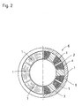
- FIG. 2 is a partially cut-away plan view of a stator showing a state in which the bobbinless coil windings of FIG. 1 whose surfaces have been insulated are assembled in winding slots of the stator of the concentrated winding motor.
- a plurality of bobbinless coil windings (concentrated, well-aligned winding type air-core coils) 1 are produced so that the shape thereof is nearly identical to each of winding slots in a stator core of a motor as shown in FIG. 1.
- the bobbinless coil windings 1 are subject to insulating process, in which the surfaces thereof are coated with an insulating thin film 2(see FIG. 2).
- an insulating thin film may be mold-formed so as to cover the surfaces of the bobbinless coil windings 1.
- the bobbinless coil windings 1 whose surfaces have been covered with the insulating film 2 are inserted into the respective winding slots 4 in the stator core 3 of the concentrated winding motor and bonded to fix in place.
- the winding assembly constituted by the bobbinless coil windings is assembled in the stator core 3.
- the stator core 3 is assembled in a yoke core 5 to obtain a stator 6.
- the method according to the present invention allows the coil winding to be mounted in the winding slots without using a bobbin or resin-formed insulator, and allows their surfaces to be insulated with little need for space.
- the method according to the present invention can increase the winding area in winding slots compared to conventional methods, making it possible to produce high-performance, concentrated winding motors.
Landscapes
- Engineering & Computer Science (AREA)
- Power Engineering (AREA)
- Manufacturing & Machinery (AREA)
- Insulation, Fastening Of Motor, Generator Windings (AREA)
- Manufacture Of Motors, Generators (AREA)
Abstract

Description
Claims (3)
- A method for manufacturing a winding assembly of a concentrated winding motor comprises the steps of:producing concentrated, well-aligned winding type air-core coils nearly identical in shape to winding slots in a rotor core or stator core of the motor;applying an insulating process to surfaces of the air-core coils, the insulating process being either coating an insulating thin film on the surfaces of the air-core coils or mold-forming an insulating thin film on the surfaces thereof; andinserting the air-core coils whose surfaces have been insulated into the winding slots, whereby the winding assembly constituted by the air-core coils is assembled in the rotor or stator core.
- A winding assembly of a concentrated winding motor produced by the method according to claim 1.
- A concentrated winding motor comprising the winding assembly according to claim 2.
Applications Claiming Priority (2)
| Application Number | Priority Date | Filing Date | Title |
|---|---|---|---|
| JP2002180968 | 2002-06-21 | ||
| JP2002180968A JP2004032830A (en) | 2002-06-21 | 2002-06-21 | Manufacturing method of winding part of concentrated winding motor |
Publications (2)
| Publication Number | Publication Date |
|---|---|
| EP1376830A2 true EP1376830A2 (en) | 2004-01-02 |
| EP1376830A3 EP1376830A3 (en) | 2006-07-05 |
Family
ID=29717531
Family Applications (1)
| Application Number | Title | Priority Date | Filing Date |
|---|---|---|---|
| EP03013717A Withdrawn EP1376830A3 (en) | 2002-06-21 | 2003-06-17 | Method for manufacturing a coil winding assembly of a concentrated winding motor |
Country Status (3)
| Country | Link |
|---|---|
| US (1) | US20040010908A1 (en) |
| EP (1) | EP1376830A3 (en) |
| JP (1) | JP2004032830A (en) |
Cited By (1)
| Publication number | Priority date | Publication date | Assignee | Title |
|---|---|---|---|---|
| CN104836349A (en) * | 2015-05-29 | 2015-08-12 | 威灵(芜湖)电机制造有限公司 | Stator and motor with stator |
Families Citing this family (15)
| Publication number | Priority date | Publication date | Assignee | Title |
|---|---|---|---|---|
| KR100585682B1 (en) | 2005-01-10 | 2006-06-07 | 엘지전자 주식회사 | Stator of reciprocating motor and its manufacturing method |
| JP4684689B2 (en) * | 2005-03-14 | 2011-05-18 | 日本電産サンキョー株式会社 | Stepping motor |
| CN1945943B (en) | 2005-10-09 | 2011-02-09 | 精工电子有限公司 | Step motor and electronic equipment |
| US20070200437A1 (en) * | 2006-02-27 | 2007-08-30 | El-Antably Ahmed M | Stator assembly and manufacturing method |
| WO2012082680A2 (en) * | 2010-12-13 | 2012-06-21 | Radam Motors, Llc | Stator used in an electrical motor or generator with low loss magnetic material and method of manufacturing a stator |
| US8572838B2 (en) | 2011-03-02 | 2013-11-05 | Honeywell International Inc. | Methods for fabricating high temperature electromagnetic coil assemblies |
| DE102011105306A1 (en) * | 2011-06-22 | 2012-12-27 | Robert Bosch Gmbh | Portable tool with wireless data transmission |
| US8860541B2 (en) | 2011-10-18 | 2014-10-14 | Honeywell International Inc. | Electromagnetic coil assemblies having braided lead wires and methods for the manufacture thereof |
| US8754735B2 (en) | 2012-04-30 | 2014-06-17 | Honeywell International Inc. | High temperature electromagnetic coil assemblies including braided lead wires and methods for the fabrication thereof |
| US9076581B2 (en) | 2012-04-30 | 2015-07-07 | Honeywell International Inc. | Method for manufacturing high temperature electromagnetic coil assemblies including brazed braided lead wires |
| US9027228B2 (en) | 2012-11-29 | 2015-05-12 | Honeywell International Inc. | Method for manufacturing electromagnetic coil assemblies |
| US9722464B2 (en) | 2013-03-13 | 2017-08-01 | Honeywell International Inc. | Gas turbine engine actuation systems including high temperature actuators and methods for the manufacture thereof |
| JP6424078B2 (en) * | 2014-02-13 | 2018-11-14 | 山洋電気株式会社 | Stator, stator manufacturing method, and motor |
| JP6864204B2 (en) | 2017-01-30 | 2021-04-28 | 竹内 啓佐敏 | Coreless electromechanical equipment and manufacturing method of coreless electromechanical equipment |
| US11041252B2 (en) | 2018-03-22 | 2021-06-22 | Honeywell International Inc. | Deposition of wear resistant nickel-tungsten plating systems |
Family Cites Families (9)
| Publication number | Priority date | Publication date | Assignee | Title |
|---|---|---|---|---|
| US3182383A (en) * | 1960-09-13 | 1965-05-11 | Gen Electric | Electromagnetic construction |
| GB1034441A (en) * | 1961-07-29 | 1966-06-29 | Pinchin Johnson & Ass Ltd | Improvements in or relating to coverings of coil windings of electrical apparatus |
| US3504431A (en) * | 1966-09-27 | 1970-04-07 | Gen Electric | Method of manufacturing insulated electrical members |
| US4394594A (en) * | 1975-07-24 | 1983-07-19 | Papst-Motoren Kg | Motor with a disk rotor |
| NL8601422A (en) * | 1986-06-03 | 1988-01-04 | Hugo Karel Krop | STEPPER MOTOR AND DISPLAY EQUIPPED WITH SUCH STEPPER MOTORS. |
| US5128574A (en) * | 1989-04-11 | 1992-07-07 | Canon Kabushiki Kaisha | Brushless motor |
| US6288341B1 (en) * | 1998-02-27 | 2001-09-11 | Hitachi, Ltd. | Insulating material windings using same and a manufacturing method thereof |
| JP3458693B2 (en) * | 1998-02-27 | 2003-10-20 | 株式会社日立製作所 | Insulation and electric winding |
| US6873236B2 (en) * | 2001-10-24 | 2005-03-29 | General Electric Company | Fault current limiter |
-
2002
- 2002-06-21 JP JP2002180968A patent/JP2004032830A/en active Pending
-
2003
- 2003-06-05 US US10/454,603 patent/US20040010908A1/en not_active Abandoned
- 2003-06-17 EP EP03013717A patent/EP1376830A3/en not_active Withdrawn
Cited By (1)
| Publication number | Priority date | Publication date | Assignee | Title |
|---|---|---|---|---|
| CN104836349A (en) * | 2015-05-29 | 2015-08-12 | 威灵(芜湖)电机制造有限公司 | Stator and motor with stator |
Also Published As
| Publication number | Publication date |
|---|---|
| EP1376830A3 (en) | 2006-07-05 |
| JP2004032830A (en) | 2004-01-29 |
| US20040010908A1 (en) | 2004-01-22 |
Similar Documents
| Publication | Publication Date | Title |
|---|---|---|
| EP1376830A2 (en) | Method for manufacturing a coil winding assembly of a concentrated winding motor | |
| US9197102B2 (en) | Stator assembly for motor having hall sensor part fixed to end of tooth of stator | |
| US7049725B2 (en) | Dynamoelectric machine stator and method for mounting prewound coils thereunto | |
| JPH0514506B2 (en) | ||
| US5680692A (en) | Fabrication of induction motors | |
| US20100156204A1 (en) | Stator core, motor using the stator core, and method of manufacturing the stator core | |
| JP7038894B2 (en) | Method of manufacturing a stator of a rotary electric machine, a rotary electric machine, a stator of a rotary electric machine, and a method of manufacturing a rotary electric machine. | |
| JP3515280B2 (en) | Method of manufacturing stator for rotating electric machine | |
| JP2011223759A (en) | Stator for revolving armature and manufacturing method thereof | |
| KR102210425B1 (en) | Transformer assembly and method for assembling the same | |
| US5323074A (en) | Armature core | |
| JP6929469B2 (en) | stator | |
| JPH0522908A (en) | Stator for rotating electric machine and manufacturing method thereof | |
| JP2000217291A (en) | Low voltage electric machine stator | |
| JPH06204058A (en) | Coil parts | |
| JPH07111747A (en) | Electric motor stator | |
| JPH01138936A (en) | Manufacture of induction motor stator | |
| JP2008259371A (en) | Rotary electric machine | |
| JPH09168257A (en) | Motor stator with improved assembly | |
| JPH08181022A (en) | Trance | |
| JPS5970154A (en) | Small-sized motor | |
| JPH01185180A (en) | How to form the coil part of a linear motor coil that has no internal connection part | |
| JPH0474935B2 (en) | ||
| GB2042813A (en) | Manufacture of combined armature and commutator | |
| JPH04364336A (en) | Stator for induction motor |
Legal Events
| Date | Code | Title | Description |
|---|---|---|---|
| PUAI | Public reference made under article 153(3) epc to a published international application that has entered the european phase |
Free format text: ORIGINAL CODE: 0009012 |
|
| AK | Designated contracting states |
Kind code of ref document: A2 Designated state(s): AT BE BG CH CY CZ DE DK EE ES FI FR GB GR HU IE IT LI LU MC NL PT RO SE SI SK TR |
|
| AX | Request for extension of the european patent |
Extension state: AL LT LV MK |
|
| PUAL | Search report despatched |
Free format text: ORIGINAL CODE: 0009013 |
|
| AK | Designated contracting states |
Kind code of ref document: A3 Designated state(s): AT BE BG CH CY CZ DE DK EE ES FI FR GB GR HU IE IT LI LU MC NL PT RO SE SI SK TR |
|
| AX | Request for extension of the european patent |
Extension state: AL LT LV MK |
|
| 17P | Request for examination filed |
Effective date: 20060804 |
|
| AKX | Designation fees paid |
Designated state(s): DE GB |
|
| 17Q | First examination report despatched |
Effective date: 20080131 |
|
| STAA | Information on the status of an ep patent application or granted ep patent |
Free format text: STATUS: THE APPLICATION IS DEEMED TO BE WITHDRAWN |
|
| 18D | Application deemed to be withdrawn |
Effective date: 20080611 |