EP1376813A1 - Electronic device, battery, and method for transporting current - Google Patents
Electronic device, battery, and method for transporting current Download PDFInfo
- Publication number
- EP1376813A1 EP1376813A1 EP02024264A EP02024264A EP1376813A1 EP 1376813 A1 EP1376813 A1 EP 1376813A1 EP 02024264 A EP02024264 A EP 02024264A EP 02024264 A EP02024264 A EP 02024264A EP 1376813 A1 EP1376813 A1 EP 1376813A1
- Authority
- EP
- European Patent Office
- Prior art keywords
- connector
- battery
- counterpart
- charge
- connectors
- Prior art date
- Legal status (The legal status is an assumption and is not a legal conclusion. Google has not performed a legal analysis and makes no representation as to the accuracy of the status listed.)
- Withdrawn
Links
Images
Classifications
-
- H—ELECTRICITY
- H02—GENERATION; CONVERSION OR DISTRIBUTION OF ELECTRIC POWER
- H02J—ELECTRIC POWER NETWORKS; CIRCUIT ARRANGEMENTS OR SYSTEMS FOR SUPPLYING OR DISTRIBUTING ELECTRIC POWER; SYSTEMS FOR STORING ELECTRIC ENERGY
- H02J7/00—Circuit arrangements for charging or discharging batteries or for supplying loads from batteries
- H02J7/60—Circuit arrangements for charging or discharging batteries or for supplying loads from batteries including safety or protection arrangements
- H02J7/685—Circuit arrangements for charging or discharging batteries or for supplying loads from batteries including safety or protection arrangements using connection detecting circuits
-
- H—ELECTRICITY
- H02—GENERATION; CONVERSION OR DISTRIBUTION OF ELECTRIC POWER
- H02J—ELECTRIC POWER NETWORKS; CIRCUIT ARRANGEMENTS OR SYSTEMS FOR SUPPLYING OR DISTRIBUTING ELECTRIC POWER; SYSTEMS FOR STORING ELECTRIC ENERGY
- H02J7/00—Circuit arrangements for charging or discharging batteries or for supplying loads from batteries
- H02J7/60—Circuit arrangements for charging or discharging batteries or for supplying loads from batteries including safety or protection arrangements
- H02J7/64—Circuit arrangements for charging or discharging batteries or for supplying loads from batteries including safety or protection arrangements against overvoltage
Definitions
- the invention relates to electronic devices and batteries to be used therein, and, more specifically, to arrangements used to transport current to such electronic devices.
- Li-Ion batteries have a nominal threshold of 4,2 Volt, and for the Nickel-Metal-Hydride (NiMH) battery units the threshold is 5,1 Volt. This corresponds to a maximum charge voltage threshold of 4,7 Volt for Li-Ion batteries and a 5,7 Volt threshold for NiMH batteries.
- the battery runs usually after some time out of charge, and therefore has to be recharged. Therefore, many systems are connectable to a battery charger, and in order to maximise the comfort of usage, the battery does not need to be removed, but the charger may just be plugged into the charger connector.
- the open circuit voltage of the charger unit may be higher than the maximum voltage limit of the circuit contained in the device. Then the portable electronic device may be broken due to a high voltage transient. For mobile phones, especially critical part has turned out to be the transmitter unit.
- Another solution would be to use a battery detector, in the manner prescribed in German patent application DE 39 26 655 A1.
- the battery detector instructs the charger equipment that a battery has been installed so that the operation of the battery charger can be modified.
- Such a solution does not offer maximal simplicity for the electromechanical design of the portable electrical device, because the battery detector part has to be implemented.
- a portable electronic device includes i) an electric circuit operable on electric current derived from a first connector preferably connectable to a first counterpart connector of a battery, ii) a charge input electrically connected to a second connector preferably adapted to charge the battery through a second counterpart connector of the battery, iii) first means for transporting an electric current from the charge input to the second connector, and iv) second means separate from the first means for transporting current from the first connector to the electric circuit.
- the first connector is electrically connected to the second connector only via third means in the battery when the battery has been installed into the device.
- Such a construction makes the design of such electronic devices much easier, because the electrical connection issues can be left to the battery manufacturer to be solved by him/herself, thus releasing research & development resources from the manufacturer of said portable electronic devices.
- the portable electronic device may further comprise a control part of the first means controllable by a control circuit responsive to the potential of the first connector or the second connector.
- a control circuit responsive to the potential of the first connector or the second connector.
- the portable electronic device includes a ground connector which has been adapted to contact a counterpart connector of the battery before other voltage-carrying counterpart connectors of the battery contact other connectors of the device. This further reduces the probability of hardware breakdowns.
- a battery to be used in a portable electronic device includes i) a first counterpart connector for connecting the second connector, ii) a second counterpart connector for connecting the first connector, and iii) means for electrically contacting the first and second counterpart connectors.
- the battery further includes a ground counterpart connector for contacting the ground connector before any other counterpart connector are electrically connected to corresponding connectors.
- This kind of constructional solution is particularly useful when combined with a corresponding design of the portable electronic device, and especially its battery socket.
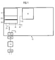
- FIG 1 shows an example of a block diagram of a portable electronic device 10 which has a battery 11 installed.
- the electric circuit 12 gets electric energy (current) needed for its normal operating from the battery 11. Therefore, the portable electronic device 10 has, as usual, a battery socket 23, and the battery 11 has battery contacts 23'. Electric current is transported from the battery 11 via battery contacts 23', battery socket 23, and conductor 22 from battery socket 23 to electric circuit 12.
- the charger 14 Whenever battery 11 needs to be recharged, the charger 14 is used.
- the mains connector 14B is connected to mains, e.g. 230 Volt AC in most European countries, and the transformer contained in the charger 14, together with some other common electric components, turn the electric current into nice DC, which then can be used for charging the battery by plugging the charger plug 14A into the charge connector 13.
- the current from the charge connector 13 is then lead to battery socket 23 using a conductor 21.
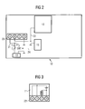
- FIG. 2 illustrates a more detailed block diagram of the portable electronic device 10.
- the battery socket 23 includes connectors A, B, C, and D which are used to make an electric contact to the battery 11, when it is present in the device.
- the charge control circuit 15 monitors the voltage over the connector B. If the voltage over connector B exceeds a preset threshold value, the charge control circuit 15 signals using control signal lead 24 that the charging of the battery 11 has to be terminated. The termination of the charging can be performed in an easy manner by changing the position of the switch SW1 to connect connectors T 1 to T 3 . Normally, when the battery 11 is being charged, the swith SW1 connects connectors T 1 and T 2 . Therefore, control part can be understood to comprise the swich SW1 and the connectors T 1 , T 2 , and T 3 , and the control part is then being controlled by the charge control circuit 15, responsive to the potential of the connectors A and/or B.
- the charge control circuit 15 and the electric circuit 15 do not take their input current from the conductor 21, i.e. from the conductor from charge connector 13 to battery socket 23.
- the charge control circuit 15 and/or electric circuit 15 is made, according to one aspect of the present invention, to obtain the operating current needed from another connector, i.e. from connector B, of the battery socket 23.
- the battery 11 has counterpart connectors A', B', C', and D' installed in the battery contacts part 23'.
- the internal wiring, i.e. conductor 25 connects counterpart connectors A' and B'.
- the couterpart connector A' is used for charging the battery, whereas the counterpart connector B' is used for current output from the battery.
- the battery 11 includes electrochemical structure known as such, and, typically, the counterpart connector D' can be used for completing the electric circuit.
- Counterpart connector C' can be used for other purposes, such as detecting the type of the battery, and so forth.
- the connectors A, B, C, and D can be arranged in such a way, the ground connector D connects the corresponding counterpart connector D' of the battery 11 before voltage-carrying counterpart connectors A', B' of the battery 11 contact other corresponding connectors A, B of the electronic device 10.
- This can be achieved, for example, by elongating the counterpart connector D' of the battery 11, so that it gets first connected.
- the portable electronic device may, in principle, be any kind of device.
- the most benefits, however, are obtained for such devices, for which the user of the device 10 may be willing to change the battery.
- Examples of such devices are mobile phones, laptops, Personal Digital Assistants, and so forth.
Landscapes
- Engineering & Computer Science (AREA)
- Power Engineering (AREA)
- Charge And Discharge Circuits For Batteries Or The Like (AREA)
Abstract
Description
- The invention relates to electronic devices and batteries to be used therein, and, more specifically, to arrangements used to transport current to such electronic devices.
- Portable electronic devices have become a part of everyday life for many consumers in western countries. Typically, instead of using a disposable battery, such as 1,5 Volt alkaline-manganese dry-pair, usually rechargeable batteries are used. For example, Lithium-Ion (Li-Ion) batteries have a nominal threshold of 4,2 Volt, and for the Nickel-Metal-Hydride (NiMH) battery units the threshold is 5,1 Volt. This corresponds to a maximum charge voltage threshold of 4,7 Volt for Li-Ion batteries and a 5,7 Volt threshold for NiMH batteries.
- As a practical limitation for the operation of the portable electronic device, the battery runs usually after some time out of charge, and therefore has to be recharged. Therefore, many systems are connectable to a battery charger, and in order to maximise the comfort of usage, the battery does not need to be removed, but the charger may just be plugged into the charger connector.
- If, for some reason, the user has removed the battery from the device, and despite this connects the charger to the device, the open circuit voltage of the charger unit may be higher than the maximum voltage limit of the circuit contained in the device. Then the portable electronic device may be broken due to a high voltage transient. For mobile phones, especially critical part has turned out to be the transmitter unit.
- One easy and very straightforward way to avoid this problem would be to lower and tighten the maximum charge voltage threshhold. At the moment, the threshold tolerances for the voltage detection is approximately 4% of the nominal voltage. On one hand, this would lead to increased cost of the charge units, because it would be technically more challenging to produce such charge units. On the other hand, then the operating range of the electronic device would be too close to the maximum charging voltage during normal condition, which would easily lead to faulty detection of an over voltage condition.
- Another solution would be to use a battery detector, in the manner prescribed in German patent application DE 39 26 655 A1. In the '655 solution, the battery detector instructs the charger equipment that a battery has been installed so that the operation of the battery charger can be modified. Such a solution, however, does not offer maximal simplicity for the electromechanical design of the portable electrical device, because the battery detector part has to be implemented.
- Therefore, it remains to be a problem, how to avoid voltage transients resulting from the connection of charging equipment into portable electronic devices, when the battery is not present in the device.
- This and other objectives of the invention can be achieved with a method and a system according to any one of the independent patent claims.
- A portable electronic device includes i) an electric circuit operable on electric current derived from a first connector preferably connectable to a first counterpart connector of a battery, ii) a charge input electrically connected to a second connector preferably adapted to charge the battery through a second counterpart connector of the battery, iii) first means for transporting an electric current from the charge input to the second connector, and iv) second means separate from the first means for transporting current from the first connector to the electric circuit. As an advantage of the portable device according to the present invention, high resistivity against voltage transients and hardware malfunction can be obtained, and this even without using any complex battery detector.
- According to one further aspect of the present invention, the first connector is electrically connected to the second connector only via third means in the battery when the battery has been installed into the device. Such a construction makes the design of such electronic devices much easier, because the electrical connection issues can be left to the battery manufacturer to be solved by him/herself, thus releasing research & development resources from the manufacturer of said portable electronic devices.
- According to one further aspect of the present invention, the portable electronic device may further comprise a control part of the first means controllable by a control circuit responsive to the potential of the first connector or the second connector. In this way also the charging of the battery can be controlled, and, further if the control circuit gets its operating current from the second connector, the probability of the control circuit breakdown because of voltage transients is further reduced.
- According to one further aspect of the present invention, the portable electronic device includes a ground connector which has been adapted to contact a counterpart connector of the battery before other voltage-carrying counterpart connectors of the battery contact other connectors of the device. This further reduces the probability of hardware breakdowns.
- A battery to be used in a portable electronic device according includes i) a first counterpart connector for connecting the second connector, ii) a second counterpart connector for connecting the first connector, and iii) means for electrically contacting the first and second counterpart connectors. Such a battery enables the use of devices like above described, and, therefore does its own part in enhancing the reliability of portable electronic devices, especially what comes to equipment damages if the battery is to be charged.
- According to one further aspect of the present invention, the battery further includes a ground counterpart connector for contacting the ground connector before any other counterpart connector are electrically connected to corresponding connectors. This kind of constructional solution is particularly useful when combined with a corresponding design of the portable electronic device, and especially its battery socket.
- In the following, the invention and its preferred embodiments are described more closely referring to the examples shown in Figures 1 to 3 in the appended drawings, wherein:
- Figure 1
- illustrates a block diagram of a portable electronic device (10), with a battery (11), and a charger (14);
- Figure 2
- illustrates a more detailed block diagram of the portable electronic device (10); and
- Figure 3
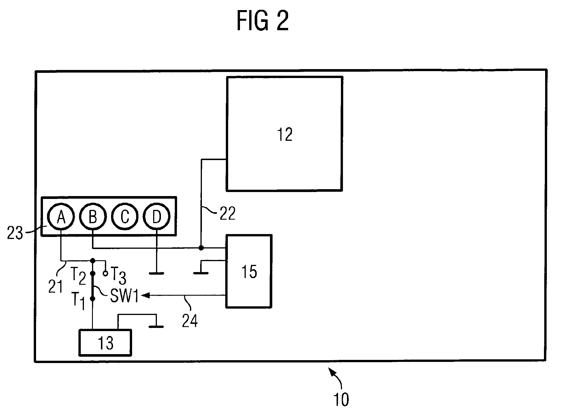
- shows a more detailed block diagram of the battery (11) to be used in the portable electronic device (10) .
- Like reference signs refer to corresponding parts and elements throughout Figures 1-3.
- Figure 1 shows an example of a block diagram of a portable
electronic device 10 which has abattery 11 installed. In normal operating mode, theelectric circuit 12 gets electric energy (current) needed for its normal operating from thebattery 11. Therefore, the portableelectronic device 10 has, as usual, abattery socket 23, and thebattery 11 hasbattery contacts 23'. Electric current is transported from thebattery 11 viabattery contacts 23',battery socket 23, andconductor 22 frombattery socket 23 toelectric circuit 12. - Whenever
battery 11 needs to be recharged, thecharger 14 is used. Themains connector 14B is connected to mains, e.g. 230 Volt AC in most European countries, and the transformer contained in thecharger 14, together with some other common electric components, turn the electric current into nice DC, which then can be used for charging the battery by plugging thecharger plug 14A into thecharge connector 13. Thecharge connector 13, in other words, then corresponds to charge input. The current from thecharge connector 13 is then lead tobattery socket 23 using aconductor 21. - Figure 2 illustrates a more detailed block diagram of the portable
electronic device 10. Thebattery socket 23 includes connectors A, B, C, and D which are used to make an electric contact to thebattery 11, when it is present in the device. - The
charge control circuit 15 monitors the voltage over the connector B. If the voltage over connector B exceeds a preset threshold value, thecharge control circuit 15 signals usingcontrol signal lead 24 that the charging of thebattery 11 has to be terminated. The termination of the charging can be performed in an easy manner by changing the position of the switch SW1 to connect connectors T1 to T3. Normally, when thebattery 11 is being charged, the swith SW1 connects connectors T1 and T2. Therefore, control part can be understood to comprise the swich SW1 and the connectors T1, T2, and T3, and the control part is then being controlled by thecharge control circuit 15, responsive to the potential of the connectors A and/or B. - As a difference to the state of art solutions, the
charge control circuit 15 and theelectric circuit 15 do not take their input current from theconductor 21, i.e. from the conductor fromcharge connector 13 tobattery socket 23. Instead of this kind of solution suffering from the danger of hardware failure to voltage transients caused by attaching and/or removing thecharger 14 to the portableelectronic device 10 when thebattery 11 is absent, thecharge control circuit 15 and/orelectric circuit 15 is made, according to one aspect of the present invention, to obtain the operating current needed from another connector, i.e. from connector B, of thebattery socket 23. - Figure 3 illustrates closerly this kind of construction. According to one aspect of the present invention, the
battery 11 has counterpart connectors A', B', C', and D' installed in thebattery contacts part 23'. The internal wiring, i.e. conductor 25 connects counterpart connectors A' and B'. The couterpart connector A' is used for charging the battery, whereas the counterpart connector B' is used for current output from the battery. Thebattery 11 includes electrochemical structure known as such, and, typically, the counterpart connector D' can be used for completing the electric circuit. Counterpart connector C' can be used for other purposes, such as detecting the type of the battery, and so forth. - In order to further reduce the risk of voltage transient and thus to decrease the fault rate of the equipment, the connectors A, B, C, and D can be arranged in such a way, the the ground connector D connects the corresponding counterpart connector D' of the
battery 11 before voltage-carrying counterpart connectors A', B' of thebattery 11 contact other corresponding connectors A, B of theelectronic device 10. This can be achieved, for example, by elongating the counterpart connector D' of thebattery 11, so that it gets first connected. To further elongate the counterpart connector D', it is possible to construct different kinds of mechanical systems, such as a metallic pin attached to a spring element with low resistivity so that the metallic pin is compressed a bit when the battery is being installed. - The portable electronic device may, in principle, be any kind of device. The most benefits, however, are obtained for such devices, for which the user of the
device 10 may be willing to change the battery. Examples of such devices are mobile phones, laptops, Personal Digital Assistants, and so forth. Especially, if the battery is located under cover, say, inside the housing of thedevice 10, the problem caused by the voltage transients, i.e. the device breaking because the user connects thecharger 14 when thebattery 11 is not present. - Although the invention was described above with reference to the examples shown in the appended drawings, it is obvious that the invention is not limited to these but may be modified by those skilled in the art without difference from the scope and the spirit of the invention. For example, the modifications of the counterpart connector D' can be replaced or accomplished with modifications of the connector D, or both.
-
- 10
- portable electronic device
- 11
- battery
- 12
- electric circuit
- 13
- charge connector
- 14
- charger
- 14A
- charger plug
- 14B
- mains connector
- 15
- charge control circuit
- 21
- conductor from charge connector to battery socket
- 22
- conductor from battery socket to electronic circuitry
- 23
- battery socket
- 23'
- battery contacts
- 24
- control signal lead
- 25
- conductor from A' to B'
- T1, T2, T3
- connectors
- SW1
- switch
- A, B, C, D
- connectors in the battery socket
- A', B', C', D'
- counterpart connectors in the battery
Claims (10)
- A portable electric device (10) including:an electric circuit (12) operable on electric current derived from a first connector (B) preferably connectable to a first counterpart connector (B') of a battery (11);a charge input (13) electrically connected to a second connector (A) preferably adapted to charge the battery (11) through a second counterpart connector (A') of the battery (11);first means (21) for transporting an electric current from the charge input (13) to the second connector (A); andsecond means (22) separate from the first means (21) for transporting current from the first connector (B) to the electric circuit (12).
- A device (10) according to claim 1, wherein: the first connector (B) is electrically connected to the second connector (A) only via third means (25) in the battery (11) when the battery (11) has been installed in/into the device (10).
- A device (10) according to any one of the preceding claims further comprising: a control part (T1, T2, T3) of the first means (21) controllable by a control circuit (15) responsive to the potential of the first connector (B) or the second connector (A).
- A device (10) according to any one of the preceding claims
characterised in that:the device (10) further includes a ground connector (D). - A device (10) according to claim 4,
characterised in that:the ground connector (D) being adapted to contact a counterpart connector (D') of the battery (11) before other voltage-carrying counterpart connectors (A', B') of the battery (11) contact other connectors (A, B) of the device (10). - A battery (11) to be used in a device according to any one of the preceding claims, the battery (11)
characterised in that
it includes:a first counterpart connector (A') for connecting the second connector (A);a second counterpart connector (B') for connecting the first connector (B); andmeans (25) for electrically contacting the first and second counterpart connectors (A', B'). - A battery (11) according to claim 6,
characterised in that
it further includes: a ground counterpart connector (D') for contacting the ground connector (D) before any other counterpart connector (A', B') are electrically connected to corresponding connectors (A, B). - A method for transmitting an electric current from a charge input (13) to an elecric circuit (12) in a device (10), the method
characterised in that
it includes the steps of:transmitting an electric current from a charge input (13) to a first connector (A), the first connector (A) being adapted to charge a battery (11) through a first counterpart connector (A') of the battery (11); andtransmitting an electric current from a second connector (B) to an electric circuit (12), the second connector (B) being adapted to recharge the battery (11) through a second counterpart connector (B') of the battery (11). - A method according to claim 8, the method further comprising the step of: electrically connecting the first counterpart connector (A') to the second counterpart connector (B').
- A mobile phone, a laptop computer, or a Personal Digital Assistant according to any one of claims 1-5, wherein: a battery according to claim 6 or 7, and/or a method according to claim 8 or 9 is used.
Priority Applications (1)
| Application Number | Priority Date | Filing Date | Title |
|---|---|---|---|
| EP02024264A EP1376813A1 (en) | 2002-10-31 | 2002-10-31 | Electronic device, battery, and method for transporting current |
Applications Claiming Priority (1)
| Application Number | Priority Date | Filing Date | Title |
|---|---|---|---|
| EP02024264A EP1376813A1 (en) | 2002-10-31 | 2002-10-31 | Electronic device, battery, and method for transporting current |
Publications (1)
| Publication Number | Publication Date |
|---|---|
| EP1376813A1 true EP1376813A1 (en) | 2004-01-02 |
Family
ID=29716882
Family Applications (1)
| Application Number | Title | Priority Date | Filing Date |
|---|---|---|---|
| EP02024264A Withdrawn EP1376813A1 (en) | 2002-10-31 | 2002-10-31 | Electronic device, battery, and method for transporting current |
Country Status (1)
| Country | Link |
|---|---|
| EP (1) | EP1376813A1 (en) |
Citations (2)
| Publication number | Priority date | Publication date | Assignee | Title |
|---|---|---|---|---|
| EP1037358A1 (en) * | 1999-03-09 | 2000-09-20 | Sony International (Europe) GmbH | Charger for batteries |
| US6150796A (en) * | 1999-10-22 | 2000-11-21 | Motorola, Inc. | Low current vehicular adapter charger |
-
2002
- 2002-10-31 EP EP02024264A patent/EP1376813A1/en not_active Withdrawn
Patent Citations (2)
| Publication number | Priority date | Publication date | Assignee | Title |
|---|---|---|---|---|
| EP1037358A1 (en) * | 1999-03-09 | 2000-09-20 | Sony International (Europe) GmbH | Charger for batteries |
| US6150796A (en) * | 1999-10-22 | 2000-11-21 | Motorola, Inc. | Low current vehicular adapter charger |
Similar Documents
| Publication | Publication Date | Title |
|---|---|---|
| US6583601B2 (en) | Portable battery charger for a mobile device | |
| US8179092B2 (en) | Lithium-ion aircraft battery with automatically activated battery management system | |
| EP2325967B1 (en) | Power supply with arc flash protection mechanism and data-processing system employing same | |
| US6404168B1 (en) | Auxiliary battery for portable devices | |
| JP5622935B2 (en) | Secondary battery management device | |
| CN101882701B (en) | Charging method and system | |
| US20130049675A1 (en) | Output connector equipped battery pack, battery-pack-and-battery-driven-device system, and charging method by using battery pack | |
| US6172892B1 (en) | Method for using battery charger adapter for military vehicles | |
| US11228062B2 (en) | Battery pack and power system comprising same | |
| US7595609B2 (en) | Battery system power path configuration and methods for implementing same | |
| US8016600B2 (en) | Electronic device and power adaptor and method for automatically disconnecting electronic device and power adaptor | |
| US20090066292A1 (en) | Battery structure and charging device adapted for the battery structure | |
| US9069538B2 (en) | Preventing dark current flow in a mobile terminal | |
| US20090265570A1 (en) | Battery structure of portable electronic device | |
| CN1075266C (en) | Intelligent variable battery charger current control device and electronic unit charging method | |
| KR20190051341A (en) | Battery Pack with locking recognition function | |
| CA3168905C (en) | Jump starting device with enhanced (turbo) boost mode | |
| CN207719838U (en) | Battery charge/discharge protection circuit | |
| EP4471932A2 (en) | Battery cabinet with blind mate connectors | |
| AU2023263493B2 (en) | Electronic device with hybrid power and charging method | |
| US10211649B2 (en) | System for generating power and capacitively charging and monitoring a battery pack | |
| EP1376813A1 (en) | Electronic device, battery, and method for transporting current | |
| CN215990263U (en) | Integrated circuit and system for battery charging and discharging protection | |
| EP1253696A1 (en) | A method of charging a battery | |
| CN107612104A (en) | Control method and device when USB flash disk charger baby charges |
Legal Events
| Date | Code | Title | Description |
|---|---|---|---|
| PUAI | Public reference made under article 153(3) epc to a published international application that has entered the european phase |
Free format text: ORIGINAL CODE: 0009012 |
|
| AK | Designated contracting states |
Kind code of ref document: A1 Designated state(s): AT BE BG CH CY CZ DE DK EE ES FI FR GB GR IE IT LI LU MC NL PT SE SK TR |
|
| AX | Request for extension of the european patent |
Extension state: AL LT LV MK RO SI |
|
| STAA | Information on the status of an ep patent application or granted ep patent |
Free format text: STATUS: REQUEST FOR EXAMINATION WAS MADE |
|
| 17P | Request for examination filed |
Effective date: 20040119 |
|
| AKX | Designation fees paid |
Designated state(s): DE FR GB |
|
| RAP1 | Party data changed (applicant data changed or rights of an application transferred) |
Owner name: BENQ MOBILE GMBH & CO. OHG |
|
| 19U | Interruption of proceedings before grant |
Effective date: 20070101 |
|
| 19W | Proceedings resumed before grant after interruption of proceedings |
Effective date: 20070702 |
|
| 19W | Proceedings resumed before grant after interruption of proceedings |
Effective date: 20100201 |
|
| RAP1 | Party data changed (applicant data changed or rights of an application transferred) |
Owner name: PALM, INC. |
|
| STAA | Information on the status of an ep patent application or granted ep patent |
Free format text: STATUS: THE APPLICATION IS DEEMED TO BE WITHDRAWN |
|
| 18D | Application deemed to be withdrawn |
Effective date: 20100503 |