EP1376792A2 - Method and apparatus for making spark plug - Google Patents
Method and apparatus for making spark plug Download PDFInfo
- Publication number
- EP1376792A2 EP1376792A2 EP03014156A EP03014156A EP1376792A2 EP 1376792 A2 EP1376792 A2 EP 1376792A2 EP 03014156 A EP03014156 A EP 03014156A EP 03014156 A EP03014156 A EP 03014156A EP 1376792 A2 EP1376792 A2 EP 1376792A2
- Authority
- EP
- European Patent Office
- Prior art keywords
- spark plug
- adjustment
- adjustment amount
- function
- ground electrode
- Prior art date
- Legal status (The legal status is an assumption and is not a legal conclusion. Google has not performed a legal analysis and makes no representation as to the accuracy of the status listed.)
- Granted
Links
- 238000000034 method Methods 0.000 title claims abstract description 113
- 238000005452 bending Methods 0.000 claims abstract description 110
- 238000003825 pressing Methods 0.000 claims abstract description 65
- 230000003247 decreasing effect Effects 0.000 claims abstract description 6
- 238000006073 displacement reaction Methods 0.000 claims description 39
- 238000004519 manufacturing process Methods 0.000 claims description 29
- 239000012212 insulator Substances 0.000 claims description 10
- 238000002474 experimental method Methods 0.000 claims description 9
- 238000012886 linear function Methods 0.000 claims description 9
- 230000006870 function Effects 0.000 description 47
- 230000015654 memory Effects 0.000 description 18
- 125000006850 spacer group Chemical group 0.000 description 17
- 238000005259 measurement Methods 0.000 description 6
- 238000004458 analytical method Methods 0.000 description 5
- 238000003860 storage Methods 0.000 description 4
- 230000002950 deficient Effects 0.000 description 3
- 238000007689 inspection Methods 0.000 description 3
- 229910000510 noble metal Inorganic materials 0.000 description 3
- 230000003287 optical effect Effects 0.000 description 3
- 238000012545 processing Methods 0.000 description 3
- 238000005304 joining Methods 0.000 description 2
- 239000000463 material Substances 0.000 description 2
- 238000012986 modification Methods 0.000 description 2
- 230000004048 modification Effects 0.000 description 2
- 238000012935 Averaging Methods 0.000 description 1
- 229910000990 Ni alloy Inorganic materials 0.000 description 1
- 238000012951 Remeasurement Methods 0.000 description 1
- 238000004364 calculation method Methods 0.000 description 1
- 238000002485 combustion reaction Methods 0.000 description 1
- 230000007547 defect Effects 0.000 description 1
- 238000001514 detection method Methods 0.000 description 1
- 238000010586 diagram Methods 0.000 description 1
- 230000005489 elastic deformation Effects 0.000 description 1
- 238000000605 extraction Methods 0.000 description 1
- 229910052751 metal Inorganic materials 0.000 description 1
- 239000002184 metal Substances 0.000 description 1
- 239000000203 mixture Substances 0.000 description 1
- 238000012544 monitoring process Methods 0.000 description 1
- 238000005482 strain hardening Methods 0.000 description 1
Images




Classifications
-
- H—ELECTRICITY
- H01—ELECTRIC ELEMENTS
- H01T—SPARK GAPS; OVERVOLTAGE ARRESTERS USING SPARK GAPS; SPARKING PLUGS; CORONA DEVICES; GENERATING IONS TO BE INTRODUCED INTO NON-ENCLOSED GASES
- H01T21/00—Apparatus or processes specially adapted for the manufacture or maintenance of spark gaps or sparking plugs
- H01T21/06—Adjustment of spark gaps
-
- H—ELECTRICITY
- H01—ELECTRIC ELEMENTS
- H01T—SPARK GAPS; OVERVOLTAGE ARRESTERS USING SPARK GAPS; SPARKING PLUGS; CORONA DEVICES; GENERATING IONS TO BE INTRODUCED INTO NON-ENCLOSED GASES
- H01T13/00—Sparking plugs
- H01T13/20—Sparking plugs characterised by features of the electrodes or insulation
-
- H—ELECTRICITY
- H01—ELECTRIC ELEMENTS
- H01T—SPARK GAPS; OVERVOLTAGE ARRESTERS USING SPARK GAPS; SPARKING PLUGS; CORONA DEVICES; GENERATING IONS TO BE INTRODUCED INTO NON-ENCLOSED GASES
- H01T21/00—Apparatus or processes specially adapted for the manufacture or maintenance of spark gaps or sparking plugs
- H01T21/02—Apparatus or processes specially adapted for the manufacture or maintenance of spark gaps or sparking plugs of sparking plugs
Definitions
- the present invention relates to a method and apparatus for making a spark plug.
- the accuracy in positioning a ground electrode and a center electrode is important. For example, there possibly occurs such a case in which the center lines of the ground electrode and center electrode with a spark gap being disposed therebetween are eccentric due to defective bending of the ground electrode, displacement of a noble metal attached to one of or each of the electrodes, etc. Such eccentricity will lead to, for example, a short life due to a partial electrode consumption and a trouble of misfire. Further, a spark gap larger than a predetermined value requires an excessively high discharge voltage so as to disable the spark plug to fire. On the other hand, a spark gap smaller than a predetermined value tends to cause short of the spark gap, etc.
- a method of treating the ground electrode by an adjustment bending by means of a bending machine having a pressing punch For example, in Japanese Patent Unexamined Publication No. 3-64882 is disclosed a method of repeatedly pressing the ground electrode by means of a pressing punch until the spark gap is adjusted to a target value while monitoring the spark gap by means of a CCD camera. In this instance, a target spark gap is set smaller than an ideal spark gap by a predetermined value with consideration of spring back of the ground electrode upon release of a pressing force on the ground electrode.
- Japanese Patent Unexamined Publication No. 11-121143 is disclosed a method of calculating the eccentricity of the center line of the noble metal chip disposed at the ground electrode and the center line of the center electrode after inspection of the spark gap and adjusting the position of the ground electrode in the width direction thereof.
- the bending process for adjusting the eccentricity between the ground electrode and the center electrode through adjustment of the position of the ground electrode in the width direction thereof is performed by measuring the eccentricity ⁇ between the electrodes by image processing, etc. and performing the bending process by the adjustment amount ⁇ and in the direction so as to eliminate the eccentricity ⁇ .
- the bending process may possibly cause the spark gap to increase or decrease and in many cases cause the spark gap to decrease. Namely, if the adjustment of the position of the ground electrode in the widthwise direction thereof is performed after the ground electrode is pressed toward the leading end surface of the center electrode so as to adjust the spark gap to a final target value gt, there is a possibility that the spark gap is deviated from the final target value gt and becomes smaller than the same.
- spark gap is larger than the final target value gt
- adjustment of the spark gap can be made by applying a force on the outer surface side of the ground electrode, i.e., the side opposite to the spark gap defining side.
- the spark gap is smaller than the target gap gt, it is necessary to bend the ground electrode outward by an adjustment jig disposed on the spark gap defining side of the ground electrode or by an adjustment jig that has portion brought into contact with the widthwise end surfaces and tightly holding therebetween the ground electrode.
- the spark gap has become smaller than the final target value gt, adjustment of the spark gap inevitably damage the ground electrode and may possibly influence the durability of the spark plug, etc.
- SB( ⁇ ) can be expected logically, the adjustment amount ⁇ to be given to the ground electrode upon the adjustment work thereof can be found from the expected SB( ⁇ ) and the measured eccentricity ⁇ .
- the bending process applied to the ground electrode to eliminate the eccentricity thereof cannot generally be approximated to a simple uniaxial tensile deformation, so that it is generally difficult to expect the SB( ⁇ ) values corresponding to various adjustment amounts ⁇ from the stress-strain curve of the material or the like.
- a method for making a spark plug having a center electrode disposed inside an insulator, a metallic shell disposed outside the insulator, and a ground electrode having a base end side connected to a leading end surface of the metallic shell and a leading end side bent so as to have a side surface that is opposed to a leading end surface of the center electrode to form therebetween a spark gap the method comprising the steps of, for adjustment of a spark gap of a spark plug work having the center electrode and the ground electrode, provisionally pressing the ground electrode of the spark plug work toward the leading end surface of the center electrode and thereby decreasing the spark gap to a predetermined value larger than a final target gap gt, after the step of provisionally pressing the ground electrode, performing an adjustment bending process for bending the ground electrode in the widthwise direction thereof so as to eliminate an eccentricity ⁇ of the ground electrode with respect to a target position, after the step of performing the adjustment bending process, measuring the spark gap g1 of the spark
- the adjustment bending process for eliminating the eccentricity of the ground electrode in the widthwise direction thereof never causes the spark gap to become smaller than the target spark gap gt and enables the spark gap adjustment to be obtained with ease.
- an apparatus for making a spark plug having a center electrode disposed inside an insulator, a metallic shell disposed outside the insulator, and a ground electrode having a base end side connected to a leading end surface of the metallic shell and a leading end side bent so as to have a side surface that is opposed to a leading end surface of the center electrode to form therebetween a spark gap
- the apparatus comprising a pair of first and second pressing devices for adjustment of a spark gap of a spark plug work having the center electrode and the ground electrode, a bending device for adjustment of an eccentricity of the ground electrode of the spark plug work, and a controller for controlling the first and second pressing devices and the bending device, the controller being programmed to actuate, for adjustment of the spark gap of the spark plug work, the first pressing device to provisionally press the ground electrode of the spark plug work toward the leading end surface of the center electrode and thereby decrease the spark gap to a predetermined value larger than a final target gap gt, actuate.
- the bending device to perform an adjustment bending process for bending the ground electrode in the widthwise direction thereof so as to eliminate an eccentricity ⁇ of the ground electrode with respect to a target position, measure, after the adjustment bending process, a spark gap g1 of the spark plug work and measure a difference (gl-gt) between the measured spark gap g1 and the final target gap gt, and actuate the second pressing device to press the ground electrode toward the center electrode when the difference (gl-gt) is positive.
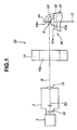
- FIG. 1 shows an electronic photography system 22 of an apparatus 1 for carrying out a method of making a spark plug according to an embodiment of the present invention.
- a spark plug (hereinafter also referred to simply as work) 50 includes a center electrode 53 that is disposed inside an insulator 52 and a ground electrode 54 that has a base end side attached to a leading end surface 51a of a metallic shell 51 disposed outside the insulator 52.
- the ground electrode further has a leading end side disposed opposite to the center electrode 53 so as to form a spark gap g between the center electrode 53 and the ground electrode 54.
- the work 50 is of such a kind that the ground electrode 54 is bent toward the center electrode 53 side so as to have a leading end side surface that faces the leading end surface of the center electrode 53 and form therebetween a spark gap g.
- the leading end portion of the center electrode 53 is comprised of a noble metal chip 53a (hereinafter also referred to as leading end portion 53a) made of a Ni alloy and welded to a leading end of a center electrode main body (no numeral).
- the eccentricity between the ground electrode 54 and the center electrode 53 is measured as the eccentricity of the ground electrode 54.
- the frontal direction of the camera 4 indicates the direction in which the center electrode 53, when viewed from the camera 4, is positioned rearward of the base end portion of the ground electrode 54 and in which the center electrode 53 and the ground electrode 54 are overlaid one upon another
- the camera 4 takes a photograph of the spark gap g of the work 50 and its surroundings in the above-described frontal direction.
- FIG. 3 when a photograph is taken with the camera 4 set in the above-described direction, the image of the place where the center electrode 53 faces the spark gap g appears on this side of the image of the ground electrode 54 while being laid over the same.
- the light 19 throws a light in the frontal direction and upon the leading end face 54a of the ground electrode 54.
- the light 19 is a LED light consisting of a surface luminous type LED or a number of light-emitting elements that are arranged on a plane and is formed with a through hole section or a transparent section at a position where an image beam B passes.
- the camera 4 is attached to a lens unit 2. Within the lens unit 2 is provided an objective optical system 15 for the work 50.
- the image beam B introduced into the objective optical system 15 is enlarged by an image forming optical system 18 and thereafter captured by the camera 4.
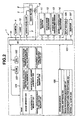
- FIG. 2 shows a main control section for an adjustment bending device 5 of the apparatus 1.
- the adjustment bending device 5 is used for performing an adjustment bending process.
- the apparatus 1 includes the computer 10 that functions as the above-described analysis device and a control section for controlling the adjustment bending device 5.
- the computer 10 includes a CPU 102, a ram 104 that provides a work area of the CPU 102 and functions as various data memories 200, 211, 212, 221, 222, 225, 226, 227 that are used in a control process and an analysis process, a ROM 103 that stores a basic computer operating system program, and an input interface 101.
- a control software 230 that realizes a control function of the apparatus 1 is installed in a storage device 105 that is constituted by a hard disk drive, etc.
- an image processing software 231 that performs an image processing such as a profile line extraction and determination process of the ground electrode 54 or the center electrode 53, and an eccentricity analysis software 232 that analyses the eccentricity between the ground electrode 54 and the center electrode 53 based on the extracted profile line data.
- an eccentricity analysis software 232 that analyses the eccentricity between the ground electrode 54 and the center electrode 53 based on the extracted profile line data.
- stored actual data 233 on an adjustment amount ⁇ and displacement amount ⁇ that will be described later.
- an input section 106 that is constituted by a key board, mouse, etc. (used for input of various settings) and a monitor 107.
- the above-described camera 4 that is constituted by a digital camera
- the light 19 lighting control unit is omitted for brevity
- a work load/unload mechanism 14 that performs attaching and detaching of the work to and from a holder 31 (refer to FIG. 4), a fixing device driving mechanism 13, a chuck drive mechanism 12, the adjustment bending device 5 and a detecting section 11 are also connected to the input/output interface 101.
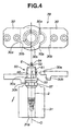
- the holder 31 has a work attaching hole 31a into which the work 50 is inserted so as to have the spark gap g on an upper side and supports a hexagonal section 57 of a metallic shell 51 at the portion around the open end of the work attaching hole 31a.
- the metallic shell 51 of the work 50 has at a base end side of a threaded portion 56 a protruded portion 55 in the form of an annular flange.
- a fixing device 29 consists of two separate fixing sections 30, 30 that are joined at joining surfaces 30s, 30s thereof.
- the fixing device 29 is abuttingly engaged at the lower surfaces around the notches 30a, 30a with the. upper surface of the protruded portion 55 and pushed in the direction of the center axis O toward the holder 31 thereby bringing the work 50 into fitting engagement with the upper surface of the holder 31. Further, the fixing device 29 is abuttingly engaged at inner circumferential surfaces of the guides 30b, 30b with the outer circumferential surface of the protruded portion 55 thereby restricting movement of the work 50 in the radial direction of the center axis O.
- FIGS. 12A and 12B show an example of a provisional pressing device 60. Since the provisional pressing device 60 is known as disclosed in Japanese Unexamined Patent Publication No. 2000-164320, a detailed description thereof is omitted for brevity and only a brief description is made.
- the provisional pressing device 60 has a provisional pressing spacer 42 that is disposed opposite to the leading end surface of the center electrode 53 of the work 50. against the provisional pressing spacer 42 is pressed the leading end side of the ground electrode 54 from the opposite side of the center electrode 53 by means of a bending punch 43 thereby performing a provisional pressing process.
- the provisional pressing device 60 has, though not shown, a provisional pressing spacer positioning mechanism section and a bending mechanism section.
- the provisional pressing spacer positioning mechanism section positions the provisional pressing spacer 42 so as to provide a predetermined gap d between the leading end surface of the center electrode 53 and the provisional pressing spacer 42. Further, the bending mechanism section drives the bending punch 43 so as to allow the ground electrode 54 to be pressed by the bending punch 43 against the provisional pressing spacer 42 that is positioned by the provisional pressing spacer positioning mechanism section as described above.
- the gap g between the ground electrode 54 and the leading end surface of the center electrode 53 can be reduced to a predetermined target gap that is larger than a final target gap gt.
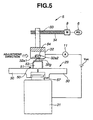
- the adjustment bending device 5 is used for performing the adjustment bending process of the ground electrode 54 and includes a bending tool 32.
- the bending tool 32 has at the lower surface side thereof a groove 32g for receiving therewithin the ground electrode 54.
- the inner side surfaces of the groove 32g that are opposed in the width direction are adapted to serve as bending operation surfaces 32a1, 32a2 for performing an bending operation in the first and second directions, respectively.
- the bending tool 32 has, for example, an integral female-threaded portion 33 that is screwed onto or threadedly engaged with a threaded shaft 34.
- the bending tool 32 By driving the threaded shaft 34 by means of the drive motor 8 in the opposite first and second directions, the bending tool 32 is abuttingly engaged at the bending operation surfaces 32a 32a2 with the ground electrode 54 and thereby applies a bending force to the ground electrode 54.
- the angular position of the drive motor 8 is detected by a pulse generator (PG) 6.
- PG pulse generator
- the servo drive unit 9 of the drive motor 8 is connected to the input/output interface 101 of the computer 10.
- the angular position of the drive motor 8 is inputted from the pulse generator 6 to the computer 10 as well as to the servo drive unit 9 by way of the input/output interface 101.
- the detecting section 11 detects contact of the bending tool 32 with the ground electrode 54.
- a detection power source voltage Vcc is applied across the metallic holder 31 and the bending tool 32.
- the detecting section 11 can be structured so as to detect a current shorted between the bending tool 32 and the holder 31 by way of the ground electrode 54 and the metallic shell 51.
- a drive instruction for driving the serve drive unit 9 in the first direction or second direction according to the direction of adjustment bending of the ground electrode 54 supplied to the serve drive unit 9 from the computer 10 is a drive instruction for driving the serve drive unit 9 in the first direction or second direction according to the direction of adjustment bending of the ground electrode 54.
- a pulse is inputted from the pulse generator 6 to the computer 10.
- the ground electrode 54 is initially out of contact with the bending tool 32, so that the detecting section 11 inputs to the computer 10 a signal indicative of having not yet detected the contact.
- the drive motor 8 rotates a predetermined amount, the ground electrode 54 and the bending tool 32 are brought into contact with each other, so that a signal indicative of having detected the contact is inputted from the detecting section 11 to the computer 10.
- the computer 10 supplies to the servo drive unit 9 at the timing it receives the signal indicative of having detected the contact an instruction for driving the drive motor 8 an angular amount corresponding to the adjustment amount ⁇
- the drive motor 8 is driven in the reverse direction to release the ground electrode 54 from the condition of being pressed for bending and the adjustment bending process is finished.
- a process finishing angular position (or pulse number) is instructed to the servo drive unit 9, and the servo drive unit 9 voluntarily performs counting of the pulse from the pulse generator 6 and recognition of the angular position for finishing the process.
- the counting of the pulse from the pulse generator 6 can be performed on the computer 10 side, and when the angular position for finishing the process is attained the computer 10 can supply to the servo drive unit 9 an instruction of stopping the drive motor 8 and driving the same in the reverse direction.
- the spark gap g is measured again. If the final target gap gt is not attained, an adjustment bending process is performed by means of an adjustment pressing device 70 shown in FIGS. 13A and 13B thereby adjusting the spark gap to a final target value.
- the adjustment pressing device 70 pushes the leading end side of the ground electrode 54 from the side thereof opposite to the center electrode 53 by using an adjustment pressing punch 90 thereby performing the adjustment pressing process.
- the spark gap g1 is measured by means of a camera 92. In the meantime, in the adjustment pressing device shown in FIGS.
- the bending process of the ground electrode 54 can be performed with a knife-like spacer for controlling the gap being interposed between the leading end surface of the center electrode 53 and the leading end portion of the ground electrode 54.
- a knife-like spacer for controlling the gap being interposed between the leading end surface of the center electrode 53 and the leading end portion of the ground electrode 54.
- FIG. 14 shows a variation of the main control section shown in FIG. 2.
- like portions to those in FIG. 2 are designated by like reference characters and will not be described again.
- the RAM 104' that functions as a memory of various data does not include the adjustment amount ⁇ memory 222, the initial approximation function F'( ⁇ ) memory 225, the actual ( ⁇ , ⁇ ) memory 226 and the adjustment amount function F( ⁇ ) memory 227 but instead thereof includes a predetermined adjustment amount ⁇ ' memory 223 and a final target deviation ⁇ t memory 224.
- the storage device 105' are not stored the actual data 233 on the adjustment amount ⁇ ' and displacement amount ⁇ .
- the final target deviation ⁇ t is, for example, determined as a predetermined value having a tolerance of ⁇ 0.1 mm.
- a drive instruction for driving the drive motor 8 in the normal or reverse direction that is determined according to the direction of adjustment bending of the ground electrode 54 is supplied from the computer 10 to the servo drive unit 9.
- the drive motor 8 is driven in the reverse direction to release the ground electrode 54 from the condition of being pressed by means of the bending tool 32.
- a provisional pressing process is performed by disposing the provisional pressing spacer 42 so as to oppose to the leading end surface of the center electrode 53 and pressing the leading end side of the ground electrode 54 against the provisional pressing spacer 42 by means of the bending punch 43 and from the side of the ground electrode 54 opposite to the center electrode 53.
- FIG. 4 the holder 31 shown in FIG. 4 is attached to a base (not shown) of the adjustment bending device 5 (refer to FIG. 5) and the work 50 is attached to the holder 31 by using the work loading/unloading mechanism 14 (refer to FIG. 2) that is constituted by a known robot arm mechanism, etc.
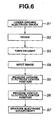
- the process steps onward are shown in FIG. 6.
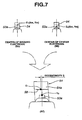
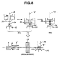
- FIGS. 7 and 8 illustrate selected main process steps.
- the work 50 attached to the holder 31 is disposed so as to allow the leading end surface 54a to face the camera 4, i.e., to orient the frontal direction (refer to FIG. 1). Concretely, as shown in (S1) and (S2) of FIG.
- the chuck 35 is moved down toward the ground electrode 54 and chuck or clamp the ground electrode 54 through sideway movement of chuck elements toward the ground electrode 54 from the opposite directions.
- the grasping surfaces of the chuck 35 are set so as to face the above-described frontal direction so that the work 50 orients the frontal direction when clamped by the chuck 35.
- step S3 the program proceeds to step S3 where the light 19 is turned on.
- step S4 an image captured by the camera 4 is inputted to the computer 10 (refer to FIG. 2) and stored in the memory 200. Then, in step S5 (refer to FIGS.
- a center position of a leading end surface 54a edge of the ground electrode 54 in the width direction thereof, which edge borders the spark gap g i.e., a center electrode center position E1 (Xm, Ym) is obtained based on the image VA and stored in the memory 211 (in this embodiment, the reference direction on the display screen is set as an y-axis and the direction perpendicular thereto is set as x-axis).
- step S6 a center position of a leading end surface edge of the center electrode 53, i.e., the center electrode center position E2 (Xm, Ym) is obtained based on the display image VA and stored in the memory 212.
- step 57 the eccentricity 6 between the both electrodes is measured or calculated by using the ground electrode center position E1 and the center electrode center position E2 and stored in the memory 221. Namely, it is determined whether the X-coordinate of the center electrode center position E2 is located on the right side or on the left side of the X-coordinate of the ground electrode center position E1 and the sign of the eccentricity 6 is determined. The sign defines the direction of the bending process of the ground electrode 54.
- the eccentricity d is calculated from the difference between the X-coordinate of the ground electrode center position E1 and the x-coordinate of the center electrode center position E2.
- the adjustment bending process is carried out by using the adjustment bending device 5 shown in FIG. 5.
- adjustment bending of the ground electrode 54 by an adjustment amount ⁇ is performed in the direction to eliminate the eccentricity ⁇ . i.e., to make the eccentricity ⁇ become zero.
- the adjustment bending process is performed by using the main control section of FIG. 2.
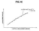
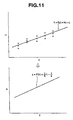
- the adjustment function ⁇ F( ⁇ ) can be obtained as a function of a first digit by performing the least square regression of the set of ( ⁇ , ⁇ ) data of the adjustment amount ⁇ and the displacement amount ⁇ .
- This method is very useful when ⁇ is considered to tend to increase nearly in proportion to ⁇ within the range of the adjustment amount ⁇ that has a possibility of being employed in manufacture. However, this tendency is supposed to vary within a predetermined range depending upon the condition of the ground electrode before bending and the composition of the material of the same. Accordingly, approximation by the least square regression is desire to be made based on an increased number (for example, five or more) of sets of ( ⁇ , ⁇ ) data.
- the following method can be employed to this end.
- n-sets of ( ⁇ , ⁇ ) data are obtained beforehand by experiment.
- the function of the n-th degree is used for obtaining the adjustment amount ⁇ till the n-th work is manufactured after the beginning of the manufacture of the spark plug.
- the adjustment amount function ⁇ F( ⁇ ) is obtained as a linear function of ⁇ that is obtained by doing the least square regression with respect to all the data sets of the works prior to the present work or the data sets of a predetermined number of works immediately before the present work, and by using the adjustment amount function the adjustment mount ⁇ is obtained.
- the accuracy in determination of ⁇ by using the least square regression can be made higher and furthermore the calculation can be considerably easier than polynomial approximation.
- the initial approximation function can be used constantly.
- FIG. 9 shows a control routine that is executed by the computer 10 (i.e., the control software 230) for determining the above-described adjustment amount ⁇ .
- a work number k is regarded as 1.
- the eccentricity is measured by the process having been described hereinbefore.
- step P9 the adjustment bending process of the ground electrode 54 is performed based on the calculated adjustment amount ⁇ -
- step P10 the eccentricity of the processed work is remeasured and is set as ⁇ ' .
- step P11 the displacement amount ⁇ is obtained from ⁇ - ⁇ ' and ( ⁇ , ⁇ ) value is stored in the memory 226 (P12). If there is no interruption of finish in step P13, the program proceeds to step P14 where increment of the work number k is executed and the work is changed to the next one. Then, the steps P3 and onward are repeated.
- the step for remeasuring the eccentricity after the adjustment process can be used as a kind of inspection step. Namely, selection of the works can be done by using the result of remeasurement of the eccentricity as the result of inspection.
- the works whose remeasured eccentricities are out of required limits are determined as defective articles and removed from a lot production line.
- the removed defective articles can, for example, undergo an additional adjustment bending process so as to allow the eccentricities thereof to be within the required limits thereby being changed into good articles.
- FIG. 15 shows a control routine that is executed by the computer 10 (i.e., control software 230') for performing the above-described adjustment bending process.
- step L1 measurement of the eccentricity 6 is performed by the process having been described hereinbefore.
- the program then proceeds to step L2 where the ground electrode 54 undergoes the adjustment bending process of the adjustment amount ⁇ ' that is stored beforehand in the memory 223.
- step L3 the drive motor 8 is once driven in the reverse direction thereby releasing the ground electrode 54 from the pressing by the bending tool 32.
- step L4 the eccentricity of the work is remeasured and its value is set as ⁇ ' .
- step L5 ⁇ is compared with a target deviation ⁇ t. If the remeasured value ⁇ ' is larger than the target deviation ⁇ t. the steps L2 and onward are repeated. Further, if the remeasured value ⁇ ' is smaller than the target deviation ⁇ t, the adjustment bending process is finished.
- step M1 a spark gap g1 is measured. Since the method for measurement of the spark gap is known as disclosed in Japanese patent provisional publication No. 11-121143, detailed description thereto is omitted. Then, the program proceeds to step M2, a deviation of the spark gap g1 from the target spark gap gt, i.e.. (gl-gt) is measured.
- step M3 it is determined whether (gl-gt) is larger than 0 (zero). If (gl-gt) is larger than zero, it is found that the spark gap has not decreased to the target spark gap gt even by the adjustment pressing process in the previous step. Thus, the program proceeds to step M4 where the adjustment pressing is performed so as to decrease the spark gap. After the adjustment pressing is released in step M5, the program returns to step M1 to repeat the steps M1 and onward. In the meantime, at the time of adjustment pressing, it will do to perform pressing of a pressing amount that is determined by consideration of spring back that is known as disclosed in Japanese patent provisional publication No. 2000-164322. Further, if the gap deviation (gl-gt) is smaller than zero, it is found that the spark gap has decreased to the target spark gap gt, so that the control is finished.
- the invention has been described above by reference to a certain embodiment of the invention, the invention is not limited to the embodiment described above. Modifications and variations of the embodiment described above will occur to those skilled in the art, in light of the above teachings.
- the shape of the provisional pressing spacer 42 is selected suitably and the spacer 42 of a suitably selected shape is used for performing a provisional pressing process and thereby decreasing the spark gap of the spark plug work to a predetermined value larger than a target spark gap gt, the spark gap can be adjusted to the target gap gt by the image processing.
Landscapes
- Engineering & Computer Science (AREA)
- Manufacturing & Machinery (AREA)
- Spark Plugs (AREA)
Abstract
Description
Claims (22)
- A method for making a spark plug (50) having a center electrode (53) disposed inside an insulator (52), a metallic shell (51) disposed outside the insulator (52), and a ground electrode (54) having a base end side connected to a leading end surface (51a) of the metallic shell (51) and a leading end side bent so as to have a side surface that is opposed to a leading end surface of the center electrode (53) to form therebetween a spark gap (g), the method comprising the steps of:for adjustment of a spark gap (g) of a spark plug work (50) having the center electrode (53) and the ground electrode (54), provisionally pressing the ground electrode (54) of the spark plug work (50) toward the leading end surface of the center electrode (52) and thereby decreasing the spark gap (g) to a predetermined value larger than a final target gap (gt);after the step of provisionally pressing the ground electrode (54), performing an adjustment bending process for bending the ground electrode (54) in the widthwise direction thereof so as to eliminate an eccentricity (δ) of the ground electrode (54) with respect to a target position;after the step of performing the adjustment bending process, measuring a spark gap (gl)of the spark plug work (50) and measuring a difference (gl-gt) between the measured spark gap (g1) and the final target gap (gt); andpressing the ground electrode (54) toward the center electrode (52) when the difference (gl-gt) is positive.
- A method according to claim 1, wherein the step of performing the adjustment bending process comprises performing the adjustment bending process for ground electrodes (54) of a plurality of spark plug works (50) to adjust positions of the ground electrodes (54) in the width direction thereof by adjustment amounts (µ) , measuring resulting displacements (λ) of the ground electrodes (54) in a pressed direction, finding the adjustment amount (µ) from an adjustment amount function µ = F(λ) that is a function of the displacement (λ),and finding, based on the adjustment amount function µ = F(λ), the adjustment amount (µ) necessary for eliminating the eccentricity (δ) of the ground electrode (54) with respect to the target position.
- A method according to claim 2, wherein the step of performing the adjustment bending process further comprises updating sets of (µ , λ) data of the adjustment amount (µ) and the displacement (λ) by (µ, λ) data newly collected upon manufacture of the spark plug, and using while updating the adjustment amount function µ = F (λ) based on the updated sets of (µ, λ) data.
- A method according to claim 3, wherein the step of performing the adjustment bending process comprises obtaining the adjustment amount function µ = F(λ) based on the sets of (µ , λ) data of all of the spark plug works (50) preceding a present spark plug work (50) or the sets of (µ , λ) data of a predetermined number of the spark plug works (50) immediately before a present spark plug work (50).
- A method according to any of claims 1 to 4,
wherein the step of performing the adjustment bending process comprises obtaining the adjustment amount function µ = F(λ) as a linear function of (λ) by least square regression of the sets of (µ , λ) data of the adjustment amount (µ) and the displacement (λ). - A method according to claim 5, further comprising the steps of:prior to beginning of manufacture of the spark plug (50), obtaining an initial approximation function µ = F'(λ) as a function of n-th degree by using the sets of (µ , λ) data having been obtained beforehand with respect to a predetermined n-number of spark plug works, and for the spark plug works till the n-th after beginning of manufacture, finding the adjustment amount (µ) from the initial approximation function µ = F'(λ); andfor the spark plug works from n+1-th onward after beginning of manufacture, obtaining the adjustment amount function µ = F(λ) as a linear function of (λ) by least square regression of the sets of (µ , λ) data of all of the spark plug works prior to a present spark plug work (50) and finding the adjustment amount (µ) from the adjustment amount function µ = F(λ).
- A method according to claim 6, wherein the step of obtaining the initial approximation function comprises preparing a required number of spark plug works (50) for experiment, making adjustments of a plurality of predetermined adjustment amounts (µ) to the respective spark plug works (50) to obtain resulting displacements (λ), and obtaining, by least square regression of thus obtained sets of (µ , λ) data, the initial approximation function µ = F'(λ) as a linear function of (λ).
- A method according to claim 8, wherein the step of obtaining the initial approximation function comprises obtaining, by the least square regression, a regression line λ = f(µ) for regression of the displacement (λ)) to the adjustment amount (µ), and obtaining the initial approximation function µ = F'(λ) as an inverse function of λ = f(µ).
- A method according to any of claims 1 to 8, wherein the step of measuring the spark gap (g) and the step of pressing the ground electrode (54) are repeated until the spark gap (g) is adjusted to the final target gap (gt).
- A method according to any of claims 1 to 9, wherein the step of performing the adjustment bending process is repeated until the eccentricity (δ) is adjusted to a final target deviation (δ t).
- A method of making a spark plug (50) having a center electrode (53) and a ground electrode (54) having a base end side joined to an end surface of a metallic shell (51) and a leading end side opposed to the center electrode (53) so as to form a spark gap (g) therebetween, the method comprising:performing an adjustment bending process of a plurality of spark plug works (50) having the center electrodes (53) and the ground electrodes (54) for making adjustments of positions of the ground electrodes (54) in the width direction thereof by adjustment amount (µ):measuring resulting displacements (λ) of the ground electrodes (54) in the width direction thereof and finding the adjustment amount (µ) from µ = F(λ) that is a function of the displacement (λ): andfinding an adjustment amount necessary for eliminating the eccentricity (δ) of the ground electrode (54) with respect to a target position based on the adjustment amount function µ = F(λ).
- An apparatus (1; 1') for making a spark plug (50) having a center electrode (53) disposed inside an insulator (52), a metallic shell (51) disposed outside the insulator (52), and a ground electrode (54) having a base end side connected to a leading end surface of the metallic shell (51) and a leading end side bent so as to have a side surface that is opposed to a leading end surface of the center electrode (53) to form therebetween a spark gap (g), the apparatus (1; 1') comprising;a pair of first and second pressing devices (60, 70) for adjustment of a spark gap (g) of a spark plug work (50) having the center electrode (53) and the ground electrode (54);a bending device (5) for adjustment of an eccentricity (δ) of the ground electrode (54) of the spark plug work (50); anda controller (10) for controlling the first and second pressing devices (60, 70) and the bending device (5);the controller (10) is programmed to:actuate, for adjustment of the spark gap (g) of the spark plug work (50), the first pressing device (60) to provisionally press the ground electrode (54) of the spark plug work (50) toward the leading end surface of the center electrode (53) and thereby decrease the spark gap (g) to a predetermined value larger than a final target gap (gt);actuate, after the provisional pressing of the ground electrode (54), the second pressing device (70) to perform an adjustment bending process for bending the ground electrode (54) in the widthwise direction thereof so as to eliminate an eccentricity (δ) of the ground electrode (54) with respect to a target position:measure, after the adjustment bending process, a spark gap (g1) of the spark plug work (50) and measure a difference (gl-gt) between the measured spark gap (g1) and the final target gap (gt); andactuate the second pressing device (70) to press the ground electrode (54) toward the center electrode (53) when the difference (gl-gt) is positive.
- An apparatus (1) according to claim 12, wherein the controller (10) is further programmed to perform the adjustment bending process for ground electrodes (54) of a plurality of spark plug works (50) to adjust positions of the ground electrodes (54) in the width direction thereof by adjustment amounts (µ), measure resulting displacements (λ) of the ground electrodes (54) in a pressed direction, find the adjustment amount (µ) from an adjustment amount function µ = F(λ) that is a function of the displacement (λ), and find. based on the adjustment amount function µ = F(λ), the adjustment amount (µ) necessary for eliminating the eccentricity (δ) of the ground electrode (54) with respect to the target position.
- An apparatus (1) according to claim 13, wherein the controller (10) is further programmed to update sets of (µ, λ) data of the adjustment amount (µ) and the displacement amount (λ) by data (µ , λ) newly collected upon manufacture of the spark plug (50), and use while updating the adjustment amount function µ =F(λ) based on the updated sets of (µ, λ) data.
- An apparatus (1) according to claim 14, wherein the controller (10) is further programmed to obtain the adjustment amount function µ = F(λ) based on the sets of (µ, λ) data of all of the spark plug works (50) preceding a present spark plug work (50) or the sets of (µ , λ) data of a predetermined number of the spark plug works (50) immediately before a present spark plug work.
- An apparatus (1) according to any one of claims 13 to 15, wherein the controller (10) is further programmed to obtain the adjustment amount function µ = F(λ) as a linear function of λ by least square regression of the sets of (µ , λ) data of the adjustment amount (µ) and the displacement (λ).
- An apparatus (1) according to claim 16, wherein the controller (10) is further programmed to:prior to beginning of manufacture of the spark plug (50), obtain an initial approximation function µ = F'(λ) as a function of n-th degree by using the sets of (µ, λ) data having been obtained beforehand with respect to a predetermined n-number of spark plug works (50), and for the spark plug works (50) till the n-th after beginning of manufacture, find the adjustment amount (µ) from the initial approximation function µ = F'(λ); andfor the spark plug works from n+1-th onward after beginning of manufacture, obtain the adjustment amount function µ = F (λ) as a linear function of (λ) by least square regression of the sets of (µ, λ) data of all of the spark plug works (50) prior to a present spark plug work (50) and find the adjustment amount (µ) from the adjustment amount function µ = F(λ).
- An apparatus (1) according to claim 17, wherein the controller (10) is further programmed to prepare a required number of spark plug works (50) for experiment, make adjustments of a plurality of predetermined adjustment amounts (µ) to the respective spark plug works (50) to obtain resulting displacements (λ), and obtain, by least square regression of thus obtained sets of (µ, λ) data, the initial approximation function µ = F'(λ) as a linear function of (λ).
- An apparatus (1) according to claim 18, wherein the controller (10) is further programmed to obtain, by the least square regression. a regression line λ = f(µ) for regression of the displacement (λ) to the adjustment amount (µ), and obtain the initial approximation function µ = F'(λ) as an inverse function of λ = f(µ).
- An apparatus (1) according to any one of claims 13 to 19, wherein the controller (10) is further programmed to measure the spark gap (g) of the spark plug work (50) and press the ground electrode (54) repeatedly until the spark gap (g) is adjusted to the final target gap (gt).
- An apparatus (1') according to claim 13, wherein the controller (10) is further programmed to perform the adjustment bending process repeatedly until the eccentricity (δ) is adjusted to the final target eccentricity (δ t).
- An apparatus (1) for making a spark plug (50) having a center electrode (53) and a ground electrode (54) having a base end side joined to an end surface (51a) of a metallic shell (51) and a leading end side opposed to the center electrode (53) so as to form a spark gap (g) therebetween, the apparatus (1) comprising:means (5; 10)) for performing an adjustment bending process of a plurality of spark plug works (50) having the center electrodes (53) and the ground electrodes (54) for making adjustments of positions of the ground electrodes (54) in the width direction thereof by adjustment amount (µ);means (10) for measuring resulting displacements (λ) of the ground electrodes (54) in the width direction thereof and finding the adjustment amount (µ) from µ = F(λ) that is a function of the displacement (λ); andmeans (10) for finding an adjustment amount (µ) necessary for eliminating the eccentricity (δ) of the ground electrode (54) with respect to a target position based on the adjustment amount function µ = F(λ).
Applications Claiming Priority (2)
| Application Number | Priority Date | Filing Date | Title |
|---|---|---|---|
| JP2002184387 | 2002-06-25 | ||
| JP2002184387 | 2002-06-25 |
Publications (3)
| Publication Number | Publication Date |
|---|---|
| EP1376792A2 true EP1376792A2 (en) | 2004-01-02 |
| EP1376792A3 EP1376792A3 (en) | 2008-01-23 |
| EP1376792B1 EP1376792B1 (en) | 2011-09-28 |
Family
ID=29717578
Family Applications (1)
| Application Number | Title | Priority Date | Filing Date |
|---|---|---|---|
| EP03014156A Expired - Lifetime EP1376792B1 (en) | 2002-06-25 | 2003-06-24 | Method and apparatus for making spark plug |
Country Status (4)
| Country | Link |
|---|---|
| US (1) | US7112112B2 (en) |
| EP (1) | EP1376792B1 (en) |
| JP (1) | JP4302445B2 (en) |
| KR (1) | KR100572639B1 (en) |
Cited By (1)
| Publication number | Priority date | Publication date | Assignee | Title |
|---|---|---|---|---|
| CN102160247A (en) * | 2008-10-06 | 2011-08-17 | 日本特殊陶业株式会社 | Method for manufacturing spark plug and device for manufacturing spark plug |
Families Citing this family (10)
| Publication number | Priority date | Publication date | Assignee | Title |
|---|---|---|---|---|
| JP4155141B2 (en) * | 2003-08-19 | 2008-09-24 | 株式会社デンソー | Spark plug manufacturing method and apparatus |
| JP4337646B2 (en) * | 2003-08-19 | 2009-09-30 | 株式会社デンソー | Manufacturing method of spark plug |
| US7581998B2 (en) * | 2005-09-08 | 2009-09-01 | Ngk Spark Plug Co., Ltd. | Method for regulating aground electrode position in spark plug |
| JP4911614B2 (en) * | 2007-06-15 | 2012-04-04 | タカノ株式会社 | Spark plug gap correction device |
| KR100973026B1 (en) * | 2007-08-14 | 2010-08-03 | 주식회사 유라테크 | Spark plug manufacturing method |
| WO2009131134A1 (en) * | 2008-04-23 | 2009-10-29 | 日本特殊陶業株式会社 | Method of manufacturing spark plug |
| JP5396535B2 (en) * | 2010-09-24 | 2014-01-22 | 日本特殊陶業株式会社 | Method for manufacturing electrode composite for forming electrode for spark plug, and method for manufacturing spark plug |
| JP6136877B2 (en) * | 2013-11-19 | 2017-05-31 | 株式会社デンソー | Plug gap measuring device, plug gap measuring method, and spark plug manufacturing method |
| JP6606534B2 (en) * | 2017-10-03 | 2019-11-13 | 日本特殊陶業株式会社 | Spark plug manufacturing method |
| DE102019209993B4 (en) * | 2018-07-11 | 2025-05-15 | Niterra Co., Ltd. | Procedure for inspecting spark plugs |
Citations (1)
| Publication number | Priority date | Publication date | Assignee | Title |
|---|---|---|---|---|
| JPH0364882A (en) | 1989-07-31 | 1991-03-20 | Nippondenso Co Ltd | Spark gap forming device for spark plug |
Family Cites Families (9)
| Publication number | Priority date | Publication date | Assignee | Title |
|---|---|---|---|---|
| JP3196537B2 (en) | 1994-11-29 | 2001-08-06 | 株式会社デンソー | Automatic adjustment device for spark gap and eccentricity of multi-polar spark plug |
| JP3479591B2 (en) | 1997-10-09 | 2003-12-15 | 日本特殊陶業株式会社 | Spark plug inspection method and device |
| JP3434461B2 (en) | 1998-11-27 | 2003-08-11 | 日本特殊陶業株式会社 | Spark plug manufacturing method and manufacturing apparatus |
| JP3389121B2 (en) | 1998-11-27 | 2003-03-24 | 日本特殊陶業株式会社 | Spark plug manufacturing method and apparatus |
| JP3936815B2 (en) | 1998-12-16 | 2007-06-27 | 日本特殊陶業株式会社 | Spark plug manufacturing method and spark plug manufacturing apparatus |
| JP2000200670A (en) * | 1999-01-06 | 2000-07-18 | Denso Corp | Spark spark generation method for spark plug |
| KR100741934B1 (en) | 2000-05-30 | 2007-07-24 | 니혼도꾸슈도교 가부시키가이샤 | Spark plug manufacturing method and apparatus |
| JP2002164149A (en) * | 2000-09-18 | 2002-06-07 | Denso Corp | How to create spark interval of spark plug |
| EP1892808A3 (en) * | 2001-02-08 | 2008-06-25 | Ngk Spark Plug Co., Ltd | Method for manufacturing spark plug and apparatus for carryingout the same |
-
2003
- 2003-06-24 KR KR1020030040963A patent/KR100572639B1/en not_active Expired - Fee Related
- 2003-06-24 JP JP2003179940A patent/JP4302445B2/en not_active Expired - Fee Related
- 2003-06-24 EP EP03014156A patent/EP1376792B1/en not_active Expired - Lifetime
- 2003-06-24 US US10/601,960 patent/US7112112B2/en not_active Expired - Lifetime
Patent Citations (1)
| Publication number | Priority date | Publication date | Assignee | Title |
|---|---|---|---|---|
| JPH0364882A (en) | 1989-07-31 | 1991-03-20 | Nippondenso Co Ltd | Spark gap forming device for spark plug |
Cited By (2)
| Publication number | Priority date | Publication date | Assignee | Title |
|---|---|---|---|---|
| CN102160247A (en) * | 2008-10-06 | 2011-08-17 | 日本特殊陶业株式会社 | Method for manufacturing spark plug and device for manufacturing spark plug |
| CN102160247B (en) * | 2008-10-06 | 2013-07-31 | 日本特殊陶业株式会社 | Method for manufacturing spark plug and device for manufacturing spark plug |
Also Published As
| Publication number | Publication date |
|---|---|
| KR100572639B1 (en) | 2006-04-24 |
| US20040029480A1 (en) | 2004-02-12 |
| US7112112B2 (en) | 2006-09-26 |
| EP1376792B1 (en) | 2011-09-28 |
| KR20030091833A (en) | 2003-12-03 |
| JP4302445B2 (en) | 2009-07-29 |
| JP2004087471A (en) | 2004-03-18 |
| EP1376792A3 (en) | 2008-01-23 |
Similar Documents
| Publication | Publication Date | Title |
|---|---|---|
| EP1376792B1 (en) | Method and apparatus for making spark plug | |
| JP3464835B2 (en) | Hole diameter and concentricity measuring device for micro cylindrical parts | |
| JP4869210B2 (en) | Spark plug manufacturing apparatus and manufacturing method | |
| US5741963A (en) | Adjustment method for spark plug and apparatus therefor | |
| JP2016040531A (en) | Working tool measuring method and measuring device | |
| JP4337646B2 (en) | Manufacturing method of spark plug | |
| JP4091355B2 (en) | Spark plug manufacturing method and manufacturing apparatus | |
| JP3430768B2 (en) | Alignment adjustment device and adjustment method | |
| JP2004006372A (en) | Spark plug manufacturing method and spark plug manufacturing apparatus | |
| JP2978076B2 (en) | Free length control device of NC coil spring manufacturing machine | |
| JPH11121143A (en) | Spark plug inspection method and device | |
| JP3299359B2 (en) | Tilt angle positioning device | |
| JP2004241267A (en) | Method and apparatus for manufacturing spark plug for internal combustion engine | |
| JP2774007B2 (en) | Measuring method of parallelism error between rotation axis and straightness axis of roundness measuring machine | |
| JP4506579B2 (en) | Manufacturing method of spark plug | |
| JP3746623B2 (en) | Spark plug inspection method, spark plug inspection device, and spark plug manufacturing method | |
| JP2000182749A (en) | Spark plug manufacturing method and spark plug manufacturing apparatus | |
| JP3792918B2 (en) | Spark plug inspection method and spark plug manufacturing method | |
| WO2005047815A1 (en) | Male thread visual testing device | |
| US20250256367A1 (en) | Positioning method, press-fitting apparatus, pin processing method, exposure apparatus, and article manufacturing method | |
| JP7819048B2 (en) | Measuring device and measuring method | |
| JP4438699B2 (en) | Manufacturing method of spark plug | |
| US20260105594A1 (en) | Method for detecting wear on ultrasonic tools | |
| JP5264456B2 (en) | Spark plug manufacturing apparatus and spark plug manufacturing method | |
| JP4882574B2 (en) | Round bar imaging device and round bar measuring device |
Legal Events
| Date | Code | Title | Description |
|---|---|---|---|
| PUAI | Public reference made under article 153(3) epc to a published international application that has entered the european phase |
Free format text: ORIGINAL CODE: 0009012 |
|
| AK | Designated contracting states |
Kind code of ref document: A2 Designated state(s): AT BE BG CH CY CZ DE DK EE ES FI FR GB GR HU IE IT LI LU MC NL PT RO SE SI SK TR |
|
| AX | Request for extension of the european patent |
Extension state: AL LT LV MK |
|
| PUAL | Search report despatched |
Free format text: ORIGINAL CODE: 0009013 |
|
| AK | Designated contracting states |
Kind code of ref document: A3 Designated state(s): AT BE BG CH CY CZ DE DK EE ES FI FR GB GR HU IE IT LI LU MC NL PT RO SE SI SK TR |
|
| AX | Request for extension of the european patent |
Extension state: AL LT LV MK |
|
| 17P | Request for examination filed |
Effective date: 20080208 |
|
| AKX | Designation fees paid |
Designated state(s): DE FR |
|
| 17Q | First examination report despatched |
Effective date: 20090928 |
|
| GRAP | Despatch of communication of intention to grant a patent |
Free format text: ORIGINAL CODE: EPIDOSNIGR1 |
|
| GRAS | Grant fee paid |
Free format text: ORIGINAL CODE: EPIDOSNIGR3 |
|
| GRAA | (expected) grant |
Free format text: ORIGINAL CODE: 0009210 |
|
| AK | Designated contracting states |
Kind code of ref document: B1 Designated state(s): DE FR |
|
| REG | Reference to a national code |
Ref country code: DE Ref legal event code: R096 Ref document number: 60338505 Country of ref document: DE Effective date: 20111201 |
|
| PLBE | No opposition filed within time limit |
Free format text: ORIGINAL CODE: 0009261 |
|
| STAA | Information on the status of an ep patent application or granted ep patent |
Free format text: STATUS: NO OPPOSITION FILED WITHIN TIME LIMIT |
|
| 26N | No opposition filed |
Effective date: 20120629 |
|
| REG | Reference to a national code |
Ref country code: DE Ref legal event code: R097 Ref document number: 60338505 Country of ref document: DE Effective date: 20120629 |
|
| REG | Reference to a national code |
Ref country code: FR Ref legal event code: PLFP Year of fee payment: 14 |
|
| REG | Reference to a national code |
Ref country code: FR Ref legal event code: PLFP Year of fee payment: 15 |
|
| REG | Reference to a national code |
Ref country code: FR Ref legal event code: PLFP Year of fee payment: 16 |
|
| PGFP | Annual fee paid to national office [announced via postgrant information from national office to epo] |
Ref country code: FR Payment date: 20200512 Year of fee payment: 18 |
|
| PGFP | Annual fee paid to national office [announced via postgrant information from national office to epo] |
Ref country code: DE Payment date: 20210525 Year of fee payment: 19 |
|
| PG25 | Lapsed in a contracting state [announced via postgrant information from national office to epo] |
Ref country code: FR Free format text: LAPSE BECAUSE OF NON-PAYMENT OF DUE FEES Effective date: 20210630 |
|
| REG | Reference to a national code |
Ref country code: DE Ref legal event code: R119 Ref document number: 60338505 Country of ref document: DE |
|
| PG25 | Lapsed in a contracting state [announced via postgrant information from national office to epo] |
Ref country code: DE Free format text: LAPSE BECAUSE OF NON-PAYMENT OF DUE FEES Effective date: 20230103 |